

Page 1
Color LCD Monitor
Model Name
32LD8800TA
37LD8800TA
USER MANUAL
This is the image of the model 32LD8800TA.
Desktop stand is optional for 37LD8800TA.
READ THE INSTRUCTIONS INSIDE CAREFULLY.
KEEP THIS USER MANUAL FOR FUTURE REFERENCE
For future reference, record the serial number of your monitor.
SERIAL NO.
This serial number is located on the rear of the monitor.
Page 2

QR65422 Printed in Japan
Page 3
USER MANUAL
ENGLISH
Thank you for purchasing the HITACHI LCD Monitor.
Please read this user manual carefully before operating
this product.
To ensure proper operation, please read and follow ALL
the instructions, especially the "IMPORTANT SAFETY
INSTRUCTIONS" and "SAFETY PRECAUTIONS".
Please keep this user manual for future reference.
LD8800TA-8th-P1-P24.indd1LD8800TA-8th-P1-P24.indd1 2005/11/099:51:382005/11/099:51:38
Page 4

CONTENTS
IMPORTANT SAFETY INSTRUCTIONS ......... 1
INTRODUCTION ...........................................2
About This Manual ................................................ 2
Trademark Credits ................................................. 2
About Software ...................................................... 2
SAFETY PRECAUTIONS ............................... 3
About the Symbols ................................................ 3
Cleaning and Maintenance .................................... 6
ABOUT LCD PANEL ...................................... 7
Common phenomena of
LCD Panel ............................................................. 7
FEATURES .................................................... 8
SUPPLIED ACCESSORIES ............................ 8
OPTION ........................................................ 8
COMPONENT NAMES ................................... 9
Main Unit ............................................................... 9
Remote Control ................................................... 10
PREPARATION ............................................11
Remote Control Batteries Installation .................. 11
Caution When Moving the Main Unit ................... 11
Safety Precaution on Main Unit Installation ......... 12
Anti-Tumble Measures ........................................ 12
CONNECTION ............................................ 13
Terminal Positions ............................................... 13
Connecting Procedure ......................................... 13
BASIC OPERATION .....................................18
Power On/Off ....................................................... 18
First Time Setup .................................................. 19
Volume UP/DOWN .............................................. 19
Mute .................................................................... 19
Input Switching to TV/AV1~5,
HDMI, and RGB .................................................. 20
Input Signal Screen Display ................................ 20
MENU OPERATION ..................................... 21
How to use the On-Screen Display
(OSD) system ...................................................... 21
Language Menu .................................................. 21
Setup Menu (TV mode) ....................................... 22
Setup Menu (AV mode) ....................................... 24
Setup Menu (RGB mode) .................................... 25
Function Menu ..................................................... 27
Picture Menu (TV/AV mode) ................................ 29
Picture Menu (RGB mode) .................................. 32
Audio Menu ......................................................... 34
Timer Menu ......................................................... 35
FUNCTION .................................................. 36
Power Swivel ....................................................... 36
About Teletext ...................................................... 37
Size Switching ..................................................... 38
Multi Picture Mode ............................................... 40
Picture Freezing .................................................. 44
Photo Input Function ........................................... 45
Audio Switching ................................................... 51
Power Save Mode ............................................... 52
DVD Player / STB Selection ................................ 53
TROUBLESHOOTING ..................................54
When Following Messages Appear
on the Screen ...................................................... 54
Symptom and Check List .................................... 54
PRODUCT SPECIFICATIONS ...................... 57
Signal Input ......................................................... 58
Recommended Signal List .................................. 59
IMPORTANT SAFETY INSTRUCTIONS
Read this instruction thoroughly.
Retain this instruction for future reference.
Heed all warnings and cautions to prevent possible danger.
Follow all instructions. Improper handling could cause personal injury and/or serious damage to the unit that may
shorten its service time.
Do not block any ventilation openings.
Install the product in accordance with the manufacture’s instructions.
Before calling for the technical support or service technician, read “TROUBLESHOOTING” (54 ~ 56) to determine
the symptoms when problems occur during installation or operation of the product.
If serious problems happen (such as smoke or an abnormal odor from the unit), turn off the Main Power, unplug the
Power Cord, and then, contact your local dealer immediately.
1
LD8800TA-8th-P1-P24.indd1LD8800TA-8th-P1-P24.indd1 2005/11/099:52:332005/11/099:52:33
Page 5
INTRODUCTION
Thank you for purchasing the HITACHI LCD Monitor. We hope that you will enjoy the great performance with this
product.
This LCD monitor has been designed to meet the International standards. However, it could cause personal injuries
and property damage if improperly handled. In order to prevent potential danger and obtain maximum benefi t from
your set, please observe the following instructions when installing, operating, and cleaning the product.
Keep this manual for future reference, and record the serial number of your set in the space provided on the front
cover page of this manual.
About This Manual
The information in this manual is subject to change without notice.
This manual has been created with extra care. In case that you have any comments or questions regarding this
manual, please contact your local dealer or our Customer Service Center.
Before operating this set, please fully understand the prerequisite such as specifi cations or constraints of the
hardware and software. We are not responsible and have no liability for any loss, damage or injury as a result of
misuse.
Reproduction, copying, use, modifi cation, and/or transmission in whole or in part of this manual are prohibited
without any prior written permission.
All other products and company names used in this manual are trademarks or registered trademarks of their
respective owners.
ENGLISH
Trademark Credits
VGA and XGA are trademarks of International Business Machines Corporation.
APPLE and Macintosh are registered trademarks of Apple Computer Inc.
VESA is a registered trademark of the Video Electronics Standard Association.
Licensed by BBE Sound, Inc. under USP5510752 and 5736897.
BBE and BBE symbol are registered trademarks of BBE Sound, Inc.
Manufactured under license from BBE Sound, Inc.
WOW, SRS and () symbol are trademarks of SRS Labs, Inc.
WOW technology is incorporated under license from SRS Labs, Inc.
SD Logo is a trademark.
HDMI, the HDMI logo and High-Defi nition Multimedia Interface are trademarks or registered trademarks of HDMI
Licensing LLC.
Even if no special notation has been made of company or product trademarks, these trademarks have been fully
respected.
About Software
You may not alter, decompile, disassemble, decrypt, or otherwise reverse- engineer the Software installed in this
product, which are prohibited by law.
2
LD8800TA-8th-P1-P24.indd2LD8800TA-8th-P1-P24.indd2 2005/11/099:52:342005/11/099:52:34
Page 6
SAFETY PRECAUTIONS
For your safety, please read the following precautions carefully before using this product. Improper use would cause serious personal injuries
and/or damage to your property or this product.
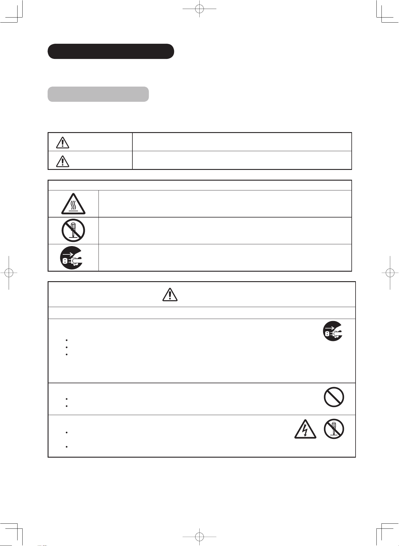
About the Symbols
The following are the symbols used in this manual and affi xed on the unit itself. Please fully understand the meanings of the symbols before
reading the instructions in this section.
WARNING
CAUTION
The triangle with illustration is intended to alert the users that there are possibilities of fi re, burst, or high temperature
if the product is handled improperly.
Each illustration within the triangle specifi es the contents in detail. (The fi gure on the left is an example.)
The circle with diagonal line and illustration is intended to prohibit the users from doing the indicated actions when
handle the product.
Each illustration within this symbol specifi es the contents in detail. (The fi gure on the left is an example.)
The blacked out circle with illustration is intended to constrain the users to follow the indicated actions when handle
the product. Each illustration within this symbol specifi es the contents in detail. (The fi gure on the left is an example.)
Never ignore the instruction. There are risks of serious injuries or possible death to the user.
Do not ignore the instruction. There are possibilities of personal injuries and/or property damage.
Other Symbols
WARNING
There is a risk of fi re, electric shock, or serious injury.
■
Unplug the power cord immediately when serious problems happen.
Serious problems such as
Smoke, abnormal odor or sound comes out from the product.
No picture, no sound or distorted picture on the display.
Foreign objects (such as water, metals etc) get inside the unit.
Do not continue using the product under these abnormal conditions.
Turn off the Main Power, unplug the Power Cord, and contact your dealer immediately.
For your safety, never try to repair the product by yourself.
■
Do not insert liquids or any foreign objects (such as metals or fl ammable items) inside the unit.
In case it happens, turn off the main power, unplug the Power Cord, and contact your dealer immediately.
Use special caution when younger children are around the unit.
■
Do not remove cover, or modify the product.
High-voltage components are installed inside of the unit. Removing covers can expose you to high
voltage, electrical shock, and other dangerous conditions.
Contact your local dealer to perform servicing such as inspection, adjustment, or repair work.
Disconnect the
plug from the
power outlet.
Do not
disassemble
3
LD8800TA-8th-P1-P24.indd3LD8800TA-8th-P1-P24.indd3 2005/11/099:52:342005/11/099:52:34
Page 7
SAFETY PRECAUTIONS (continued)
WARNING
There is a risk of fi re, electric shock, or serious injury.
■
Do not place any objects on top of the unit.
Objects such as
Liquid containers (vase, fi sh tank, fl owerpot, cosmetics or liquid medicine).
If water or any liquid spill onto the unit, it may cause short-circuit and result in fi re or electrical shock.
In case that it happens, turn off the Main Power, unplug the Power Cord, and contact your dealer immediately.
Do not place anything heavy on top of the unit.
Do not climb on or hang from the unit.
Do not let your pets get on top of the unit
■
Do not expose this unit to rain or moisture.
Never use this unit in the bathroom or shower room.
Beware when you use this product outside, especially in rainy, or snowy weather, and at the beach or
waterfront.
When the product gets wet, it could cause fi re or electrical shock.
■
Unplug this unit during lightning storm.
To reduce the risk of electrical shock, do not touch the product when starts lightning.
■
Do not do anything that may damage the Power Cord.
Do not damage, modify, twist, forcibly bend, heat, or pull excessively the Power Cord.
Do not place heavy objects (including the unit itself) on top of the Power Cord.
If the Power Cord is damaged, contact your dealer for repairs or exchange.
ENGLISH
Disconnect the
plug from the
power outlet.
■
Use only with designated power supply voltage.
To prevent the risk of fi re and electrical shock, operate this product only with the power supply voltage indicated on the
unit.
■
Beware not to drop or have any impact on the unit.
Take extra care while moving the unit.
There is no protection glass on the surface of the LCD panel. Thus, do not press the panel surface with your fi ngers or
hands. Or do not hit anything against the monitor. These actions would damage the LCD cells or the panel surface and
could cause the failure or personal injuries.
In case that you drop the unit or the cabinet is damaged, turn off the Main Power, unplug the Power Cord and contact
your local dealer immediately.
Continuing use of the product with above conditions would cause fi re or electrical shock.
■
Clean dust or metals on or around the blade of the power plug regulary.
Continuing use of the product with above condition may cause fi re or electrical shock.
Always unplug the Power Cord fi rst, and clean the blade with dry cloth.
■
Do not place the unit on an unstable surface.
Unstable places such as
Sloped place or shaky rack, table, stand or trolly.
If the unit falls down, it could cause personal injury.
4
LD8800TA-8th-P1-P24.indd4LD8800TA-8th-P1-P24.indd4 2005/11/099:52:352005/11/099:52:35
Page 8
SAFETY PRECAUTIONS (continued)
CAUTION
■
Do not place the unit at the dusty place.
It could cause malfunction.
■
Do not cover or block any ventilation holes on the product.
The monitor would overheat, and it could cause fi re or damage the product which may shorten its service life.
Install the product in accordance with the instructions in this manual.
Do not place the unit with ventilation side down.
Do not install the unit on the carpet or bedclothes.
Do not cover the monitor with table cloth etc.
■
Be sure to ground the earth cable correctly.
Especially when you use Power Cord adapter, be sure to connect the earth cable to the ground terminal. Incorrect
connection would cause fi re or electrical shock.
For your safety, always make sure to unplug the Power Cord before connect or disconnect the earth cable .
■
Follow the Anti-tumble measures in this manual.
If the monitor tumble down, there is a risk of personal injury and possible death. Also, it would damage the product
seriously.
Supply connect
the ground wire.
■
Do not install this product near the medical devices.
To prevent malfunction of the medical devices, do not use this product and the medical devices in the same room.
■
Do not place the CRT-based television near the speaker of the LCD monitor.
It could cause the partial discoloration or blurring of the image on the CRT-based television.
Please install it away from the speaker of the LCD monitor.
■
Disconnect all of the external connection cables and detach the anti-tumble measures before
moving the unit.
It may cause fi re, electrical shock, or personal injuries.
■
Connect the power plug securely.
Improper connection will cause overheat and may result in fi re.
Do not touch the blade of the plug while connecting it to the wall socket. It could cause electrical shock.
If the plug is not fi tted for the wall socket, contcat your dearly for replacement.
■
Do not handle the Power Cord with wet hands.
It could result in electrical shock.
■
Do not pull the cord when you unplug the Power Cord.
It may damage the cord and could result in fi re or electrical shock.
Hold the plug when disconnecting it.
■
Unplug the Power Cord when unused the product for long periods of time.
■
Handle the batteries properly.
Improper or incorrect use of the batteries may cause corrosion or battery leakage, which could cause fi re, personal
injury or taint damage to the property.
Use only the types of the batteries which are indicated in this manual.
Do not insatall new batteries with used ones.
Install the batteries correctly by following the polarity (+ and -) indications on the battery compartment.
Do not despose the used batteries as domestic waste. Dispose them in accordance with the local regulations.
5
LD8800TA-8th-P1-P24.indd5LD8800TA-8th-P1-P24.indd5 2005/11/099:52:362005/11/099:52:36
Page 9
SAFETY PRECAUTIONS (continued)
PRECAUTIONS
■
Do not install the unit in high temperature.
It could damage the cabinet or parts of the product.
Do not install near any heat sources such as radiator, heat registers, stoves, or other apparatus that produce heat.
Keep the unit out of direct sunlight. It could increase the temperature of the unit and cause malfunction.
■
Viewing Advice
The lighting of the environment in which the product is used should be appropriate. Too bright / dark environment is not good for
your eyes.
Take time to relax your eyes occasionally.
When you use this product, keep away from the monitor 3~7 times of the vertical length of the panel. This is the best viewing
distance in order to protect your eyes against eyestrain.
Adjust the volume in appropriate level, especially during the night.
■
When transporting this product:
When the product needs to be transported due to moving or repair, use the carton box and buffer material comes with this
product.
Do not keep this product lying sideways during transportation. It could damage the panel surface or degrade the phosphors
of the panel.
■
Keep away from the monitor when you use radio.
This monitor is designed to meet the international EMI standards due to prevent the interference against the radio. However,
the unit may generate noise in the radio.
If the noise is in the radio, please try the following actions.
Adjust the direction of the radio antenna in order not to receive the interference radio wave from the unit.
Keep the radio away from the monitor.
Use coaxial cable for the antenna.
■
About the infrared communication devices:
The infrared communication devices such as cordless microphone or cordless headphone may not be available around the monitor.
It is because of the communication failure. Please note that this is not malfunction.
■
When you dispose this product at the end of its life, follow the regulations at your residential area.
For more information, contact the local authority or the dealer where you purchased the product.
ENGLISH
Cleaning and Maintenance
Please make sure to unplug the power cord before cleaning the monitor.
■
How to clean the LCD panel of the monitor.
Wipe the panel with a lint-free and dry cloth in order to prevent damage to the panel surface.
Do not use a chemical cloth or cleaner. Depending on the ingredients, it may cause discoloration and damage the panel surface.
Do not wipe with a hard cloth or rub hard. It may hurt the panel surface.
In case of the greasy dirt such as fi ngerprint, wipe with a lint-free cloth moistened by a diluted neutral detergent solution, and then
wipe with a soft and dry cloth.
Do not use a spray cleaner. It could cause malfunction.
■
How to clean the cabinet of the monitor.
The following may cause crack, deformation, and paint peeling.
Do not wipe the cabinet with benzene, thinner, and other chemical products.
Do not spray volatile solutions such as insecticide over the cabinet.
Do not leave the cabinet in prolonged contact with plastic or rubber materials.
Do not use a chemical cloth, cleaner or wax. Depending on the ingredients, it may cause crack and deformation.
Use a lint-free cloth to clean the cabinet and control panel of the monitor. In case of the heavy dirt, wipe with a soft cloth moistened
by a diluted neutral detergent solution, and then wipe with a soft and dry cloth.
Never use the following detergents. It could cause crack, discoloration, and scratch.
Acid/ alkaline detergent, alcoholic detergent, abrasive cleaner, powder soap, OA cleaner, car wax, glass cleaner, etc.
6
LD8800TA-8th-P1-P24.indd6LD8800TA-8th-P1-P24.indd6 2005/11/099:52:372005/11/099:52:37
Page 10

ABOUT LCD PANEL
Common phenomena of LCD Panel
The following are the common phenomena when operating LCD Panel due to its structural reason.
Please note that they are not malfunctions.
Defective Spots on Panel
The LCD panel is manufactured with high-precision technology. However, there might be some spots that are not
emitted, brighter than the others, or in different colors, etc.
Surface on Panel
The LCD panel displays images by blinking the fl uorescent lamps internally. This could raise the temperature of the
display surface.
In addition, do not impact strongly on the surface of the panel because LCD panel is made with fi ne processing
glass.
Residual image
When a still image or menu is displayed on the screen for a short time (about a minute) and then switches to another
image, it may leave an “after-image” on the screen.
The residual image will disappear on its own.
The Usage under the Low Temperature Environment
Because of the structural characteristics of the LCD panel, the response speed of the LCD panel becomes slower
when the ambient temperature around the monitor becomes too low. In some cases, it may cause the residual
image.
The residual image will disappear on its own as the temperature goes up and back to normal.
7
LD8800TA-8th-P1-P24.indd7LD8800TA-8th-P1-P24.indd7 2005/11/099:52:372005/11/099:52:37
Page 11
FEATURES
Enjoy not only beautiful and high quality pictures on the display, but also various kinds of useful and convenient
functions in your daily life!
Large-screen and high-defi nition LCD panel.
Improved Digital signal processor.
High quality sound with deeper, richer and dynamic bass tones.
Accept more digital input devices with 2 HDMI terminals.
Great diversity of connecting terminals to cover wide range of audio-visual equipments.
Enjoy the image from PC with large, high-defi nition LCD screen.
New Photo Input function with selectable Background Music.
SD Card Slot installed.
Easy-to-use On-Screen Display system operating with Remote control.
Low power consumption with Power Saving feature.
Motorized Power Swivel feature. (Desktop stand is optional for 37LD8800TA.)
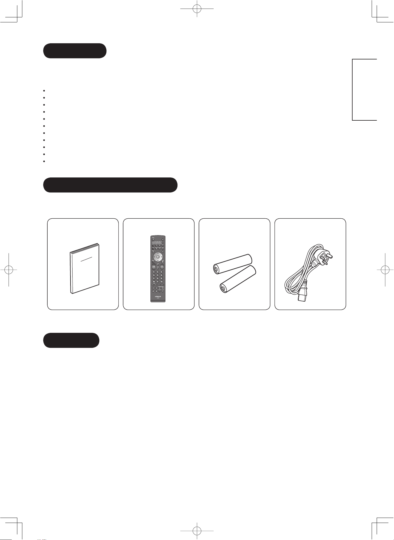
SUPPLIED ACCESSORIES
Check the supplied accessories before installation.
In case of missing or damaged, please contact the dealer immediately.
ENGLISH
User Manual Remote Control AA size batteries
X2
*The type of power plug provided may be different from this drawing for some countries.
OPTION
Ask your local dealer for further details.
Desktop Stand : SD8G4237 (for 37LD8800TA)
Power Cord
(BS Type)*
8
LD8800TA-8th-P1-P24.indd8LD8800TA-8th-P1-P24.indd8 2005/11/099:52:382005/11/099:52:38
Page 12
COMPONENT NAMES
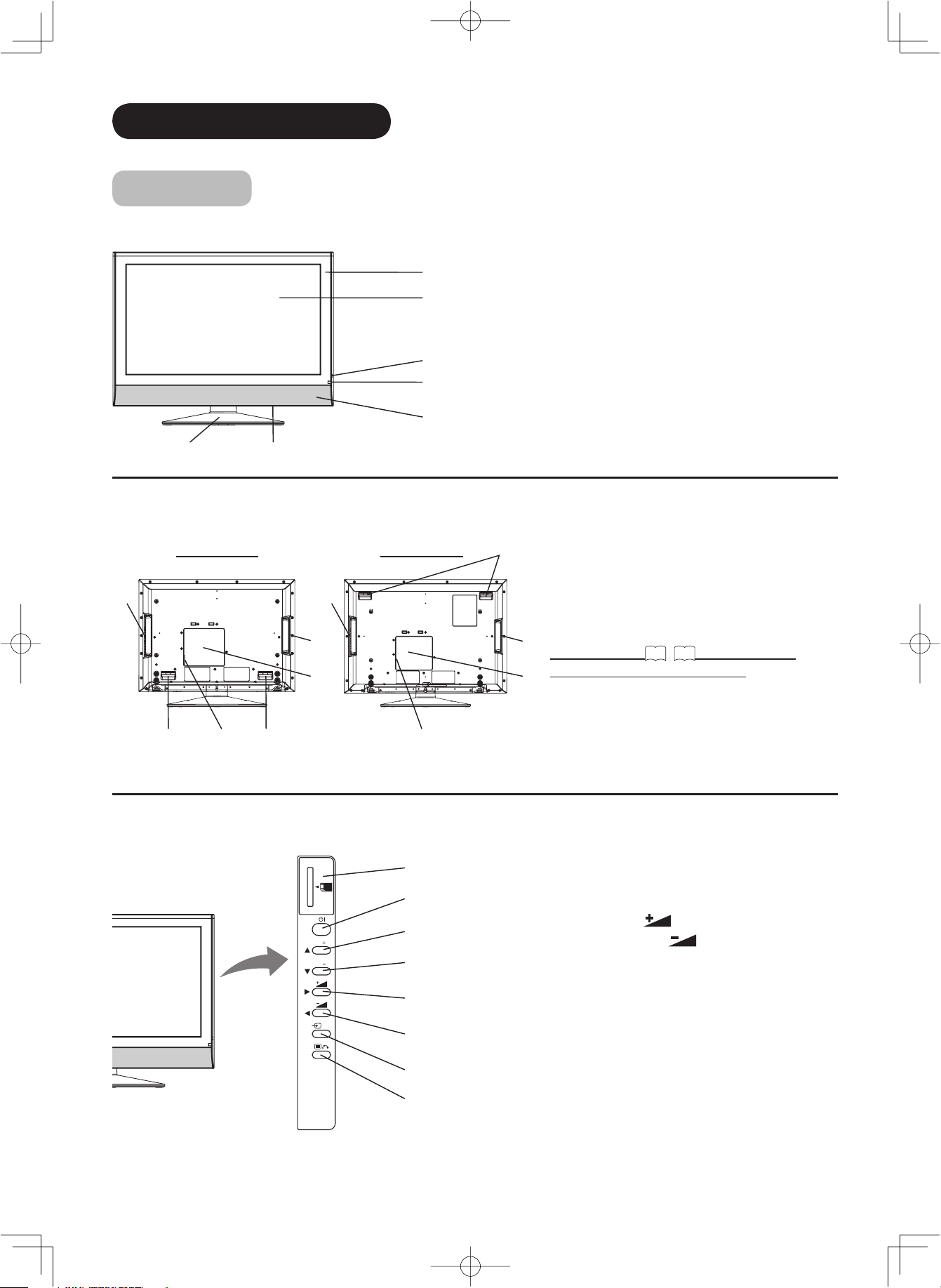
Main Unit
Front Panel
q
w
e
r
t
Cabinet
q
Panel
w
Indicating Lamp
e
Remote Control Receiver
r
Speaker
t
Main Power Switch (on the bottom surface)
y
Desktop Stand (optional for 37LD8800TA)
u
u
y
Rear Panel
32LD8800TA 37LD8800TA
t
t
w
e
qrq
Control Panel (including Card Slot)
SD MEMORY
CARD
PUSH-EJECT
P
P
r
q
w
e
r
t
OK
y
q
Handgrips
q
Side Input
w
Terminal Board (External Device Connection)
e
Power Cord Socket
r
Control Panel (see below for details)
t
w
Please refer to 13~17 for the detailed
information for the connections.
e
SD Memory Card Slot
q
Sub Power button
w
Channel UP/▲button
e
Channel DOWN/▼button
r
Volume UP
t
Volume DOWN
y
Input Select /OK button
u
Menu / Return button
i
/►button
/◄button
u
i
PH35814
9
LD8800TA-8th-P1-P24.indd9LD8800TA-8th-P1-P24.indd9 2005/11/099:52:382005/11/099:52:38
Page 13
COMPONENT NAMES (Continued)
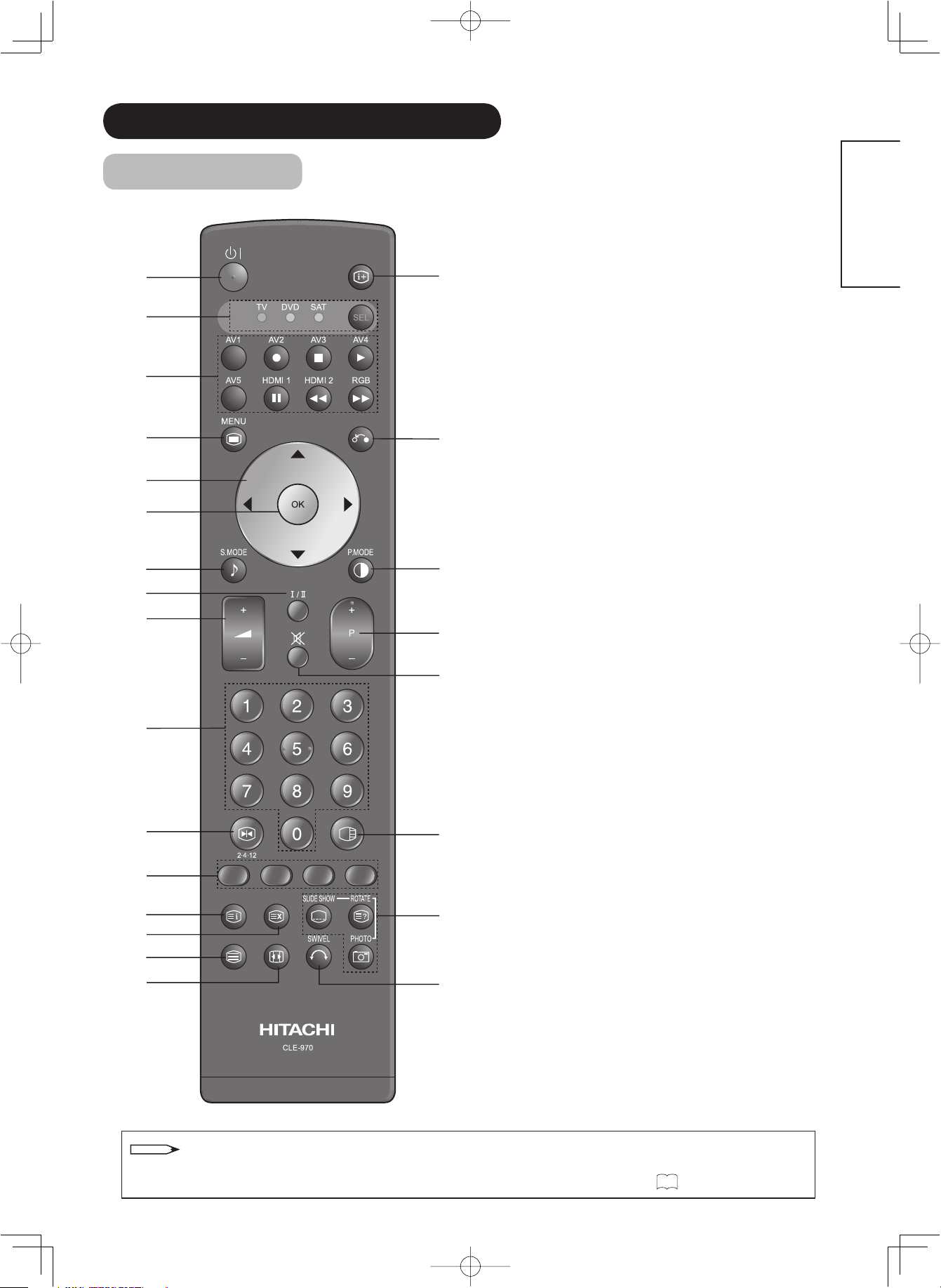
Remote Control
q
k
w
e
r
l
t
y
u
1(
i
o
2)
2!
a
s
2@
d
f
2#
g
h
j
2$
Sub Power
q
Function Select (TV/DVD/SAT)
w
Press this button to select function mode
indicating LED lamp.
Normally, select “TV”.
Input Select/DVD Control/Photo Input Control
e
Press this button to change input mode.
In addition, you can use these buttons while
operating the selected brand of DVD player or
Photo Input function.
Menu
r
Cursor
t
OK
y
Sound Mode
u
Sound mode can be changed each time pressed
in the following sequence. Movie→Music→
Speech→Favorite
CHI/II
i
This is exclusively for TV audio A2/NICAM mode.
Volume Up/Down
o
Program Select
a
Press these buttons to select a TV program
directly.
Freeze/Multi Mode [Hold]
s
Press this button to change the picture to freeze
mode. Press it again to return to normal picture.
In addition, during multi-picture mode, each time
press this button, the picture is changed to 2, 4,
and 12 multi mode.
[Color (Red, Green, Yellow, Blue)]
d
[Index]
f
Time [Cancel]
g
Pressing this button can indicate the time by On-
Screen display when receiving a TV program on
the screen.
TV/Text [TVText]
h
This switches between the TV mode and the
Teletext mode.
Zoom [TextTV+Text]
j
Press this button to change picture size.
Recall
k
Pressing this button shows the input signal
status.
Return
l
You can use this to return to the previous menu.
Picture Mode
1(
Picture mode can be changed each time pressed
in the following sequence. Dynamic→Natural→
Cinema
Channel Up/Down
2)
Mute
2!
Multi Picture
2@
Press this button to change the picture to multi-
picture mode. Press it again to return to normal
picture.
Photo Input (Photo/Rotate/Slide Show)
2#
These buttons are to display and control the
pictures from digital still camera or USB card
reader.
Swivel (
2$
This function is to rotate TV. Select the degree
of rotation with cursor key.
Desktop Stand is optional for 37LD8800TA.
ENGLISH
)
NOTE
Some buttons are only for Teletext mode, and other buttons have different functions in Teletext mode from
37
the use of TV mode. Those buttons are indicated by [ ]. Refer to "About Teletext" on
LD8800TA-8th-P1-P24.indd10LD8800TA-8th-P1-P24.indd10 2005/11/099:52:412005/11/099:52:41
.
10
Page 14
PREPARATION
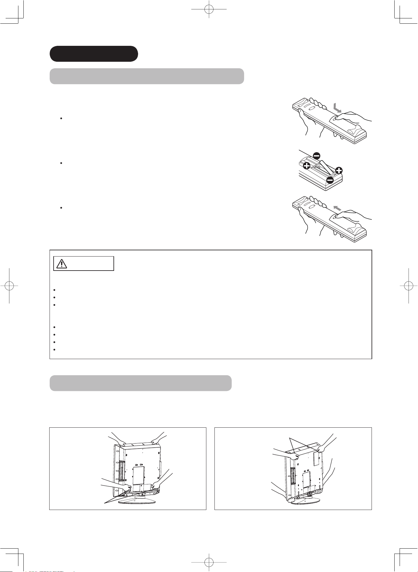
Remote Control Batteries Installation
This remote control operates on 2 “AA” batteries.
1. Open the battery compartment cover
Slide open the battery compartment cover on the backside of the
remote control in the direction of an arrow.
2. Install the batteries
Install 2 “AA” batteries (included) making sure the polarities match
the indication inside the compartment.
3. Close the battery compartment cover.
To close the battery compartment cover, slide the cover in the
direction of an arrow till it clicks shut.
CAUTION
It could cause corrosion or battery leakage and may result in physical injury
and/or property damage including fi re.
Never mix used and new batteries in the device.
Replace all the batteries in a device at the same time.
Remove the batteries if the remote control is not going to be used for an extended period of time.
To avoid possible failure, read the following instructions and handle the
remote control properly.
Do not drop or have an impact on the remote control.
Do not spill water or any liquid on the remote control.
Do not place the remote control on the wet object.
Do not place the remote control under the direct sunlight or near sources of excessive heat.
Caution When Moving the Main Unit
As this product is heavy, whenever it is moved, two people are required to transport it safely.
When transferring the unit, hold the unit by using the handgrips at the backside of the panel. (See the fi gures below
for details.)
32LD8800TA:
37LD8800TA:
Handgrips
Handgrips
11
LD8800TA-8th-P1-P24.indd11LD8800TA-8th-P1-P24.indd11 2005/11/099:52:422005/11/099:52:42
Page 15
PREPARATION (continued)
Safety Precaution on Main Unit Installation
Read SAFETY PRECAUTIONS (
3
to
6
) carefully besides this page.
*When installing the monitor, use the Desktop Stand (SD8G4237/ optional for 37LD8800TA). Please refer to the user
manual of the stand. The Desktop Stand has been used for the illustration in this manual.
When installing the main unit, be sure to use the specifi ed mount units in order to obtain maximum performance
and maintain the safety.
We assume no responsibility or liability for personal injuries or property damages caused by use of other mount
units or improper installation.
As for the installation instruction, please read each user manual of the mount units: for Desktop Setup, Wall
Mounting, and Ceiling Mounting.
In case of using Wall or Ceiling Mounting unit, by contacting your local dealer, ask the specifi ed installation
specialist to set up. Never attempt to install it by yourself. It could cause injuries or damages.
Cord
or
chain
Clamp
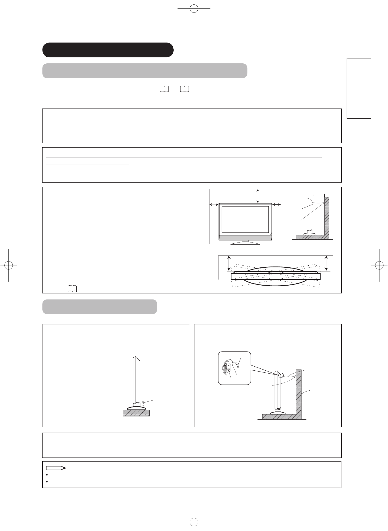
10cm or more*
Please leave the adequate space around this monitor in
order to avoid increasing the internal temperature and
keep safety while using swivel function.
Make sure not to block any ventilation holes.
Do not install the monitor in the small space such as
10cm
or more
30cm
or more
10cm
or more
inside the rack, closet or the box.
Leave more than 10cm of clearance from each side of
monitor and 30cm from the top of monitor to wall.
Without Swivel function: Leave at least 10cm of clearance
behind rear monitor.
With Swivel function: Leave the adequate space to obtain
the maximum performance of Swivel Function.
(32LD8800TA:25cm/ 37LD8800TA:29cm)
36
Refer to
for Swivel Function.
ENGLISH
Anti-Tumble Measures
Install in a stable place and implement safety measure against overturning.
Securing on desktop
Use two wood screws to secure the set fi rmly in
position by fastening them to the screw holes at the
rear of the stand as shown in the diagram.
For 32LD8800TA, please get
the commercially available
wood screws for the stand.
For 37LD8800TA, the wood
screws are supplied with the
optional stand.
Wood screw
Two places
Securing to ceiling
Using a commercially available cord, chain, and clamp, secure the set to a ceiling.
NOTE
For more information regarding the mounting of the unit, please contact your dealer.
Loosen a cord or chain enough while operating power swivel to avoid physical injury.
Securing to a wall or pillar
Using a commercially available cord, chain, and
clamp, secure the set to a wall or pillar.
cord or chain
hook
screw
clamp
cord or chain
Wall or Pillar
12
LD8800TA-8th-P1-P24.indd12LD8800TA-8th-P1-P24.indd12 2005/11/099:54:012005/11/099:54:01
Page 16
CONNECTION
OK
P
P
SD MEMORY
CARD
PUSH-EJECT
PH35814
INPUT(AV5)
R
L/MONO
AUDIO
VIDEO S-VIDEO
PH35826
Licensed by BBE Sound, Inc. under USP5510752 and 5736897.
BBE and BBE symbol are registered trademarks of BBE Sound, Inc.
WOW, SRS and symbol are trademarks of SRS Labs, Inc.
SERVICE USE ONLY
INPUT(RGB)
ANALOG RGB
INPUT(HDMI)
PC
AUDIO
AUDIO
A C
INPUT
(AV1)
INPUT
(AV2)
INPUT
(AV3)
INPUT
(AV4)
ANT
OUTPUT
AUDIO AUDIO AUDIO AUDIO AUDIO
L
MONO
C
L
MONO
C
L
MONO
C
LL
MONO
C
RRRRR
VIDEO
VIDEO
VIDEO
PBPRPB
PR
Y/VIDEO Y/VIDEO
S-VIDEO
SUB
WOOFER
POWER SWIVEL
HDMI2
HDMI1
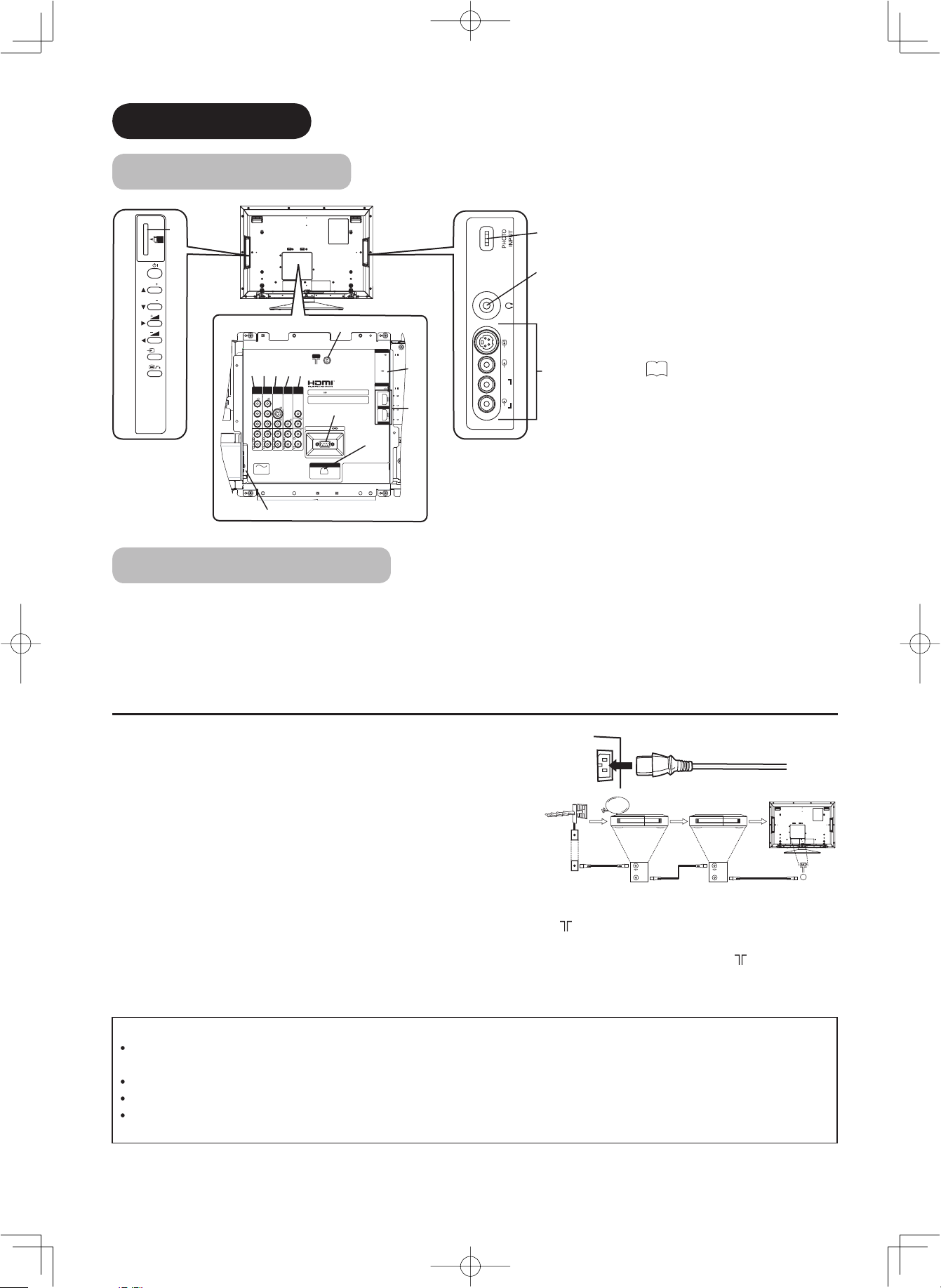
Terminal Positions
h
ertyu
q
i
w
o
a
s
g
f
d
Rear
Power Cord Socket
q
Aerial Socket
w
AV1
e
AV2
r
AV3
t
AV4
y
Monitor Out and Sub Woofer
u
Service use only
i
Power Swivel Terminal
o
(see 36)
PC Connection terminals
a
(D-sub 15 pin and mini stereo for
Audio)
HDMI1, 2 and mini stereo for Audio
s
Side
AV5
d
Headphone input
f
Photo Input terminal
g
SD Memory Card slot
h
Connecting Procedure
Your monitor is ready for various kinds of connections. Make a connection in the following steps. Be sure to turn off
the Main Power fi rst when connecting external equipments.
1. Connect Power Cord to the rear panel.
2. Connect Aerial Lead.
3. Connect your external equipments to the monitor if any.
4. Connect the Power Plug to the Wall Socket.
1. Connecting Power Cord to the Rear Panel
Connect Power Cord to the monitor.
* Make sure not to connect the Power Plug to the Wall Socket until
all connections are completed.
STB
2. Connecting Aerial Lead.
There are two ways to connect Aerial Lead.
When you do not have any other external equipment:
q
Connect the Aerial Lead directly into the Socket at rear panel.
When you have one or more external devices to connect:
w
1. Use RF cable to connect between each equipment and Antenna.
2. Connect the Aerial Lead to an equipment‘In’Socket marked
3. Connect the RF cable from the equipment ‘Out’ to the other equipment ‘In.’
4. Then, connect from the equipment ‘Out’ to “ANT” on the LCD screen Socket on marked .
IN
OUT
[Example: Connecting Antenna
VCR
IN
OUT
through STB and VCR]
Precautions when connecting the aerial
Please use a coaxial cable which is free from interference to connect the aerial. Avoid using a parallel fl at feeder
wire as interference may occur, causing reception to be unstable and stripe noise to appear on the screen.
Avoid using indoor aerial as this may be affected by interference. Please use CATV net or outdoor aerial.
For safety, install an external aerial conforming to AS1417.1 (applicable for Australia only)
If there are noise appearance in the picture of VHF-Low band channel, please use the double-shielded cable (not
provided) for RF LEADS to reduce the noise.
13
LD8800TA-8th-P1-P24.indd13LD8800TA-8th-P1-P24.indd13 2005/11/099:54:492005/11/099:54:49
Page 17
CONNECTION (continued)
Connecting Procedure (continued)
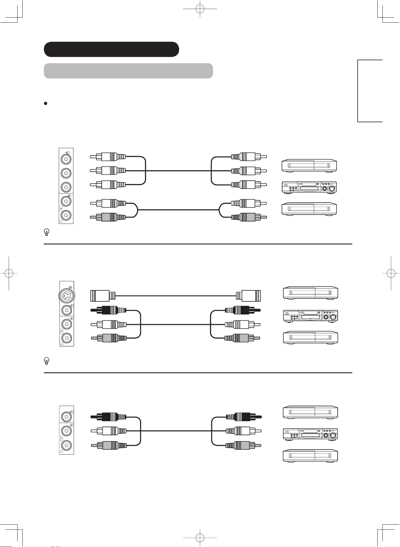
3. Connecting to External Equipment
Terminals on Rear
A
V1 and AV2
Y/VIDEO input of your selected equipment is Y signal or Video signal, it automatically regards as Component or Composite.
When using as Composite, do not insert the jacks into PB or PR.
Y/VIDEO
PB
PR
AUDIO
L
C
R
If your external device has a Component terminal, COMPONENT connection is recommended for higher quality picture.
AV3 can be connected to the equipment with an S-Video output and Composite output.
can be connected to the equipment with either Component or Composite output. Depending on whether the
IN OUT
MONO
[Example]
VCR
DVD player
Set-Top Box
[Example]
S-VIDEO
IN OUT
VCR
ENGLISH
L
C
R
VIDEO
AUDIO
MONO
DVD player
Set-Top Box
If your external device has a S-video terminal, S-VIDEO connection is recommended for higher quality picture.
AV4 can be connected to the equipment with composite output.
[Example]
VCR
IN OUT
DVD player
Set-Top Box
AUDIO
L
C
R
VIDEO
MONO
14
LD8800TA-8th-P1-P24.indd14LD8800TA-8th-P1-P24.indd14 2005/11/099:54:502005/11/099:54:50
Page 18
CONNECTION (continued)
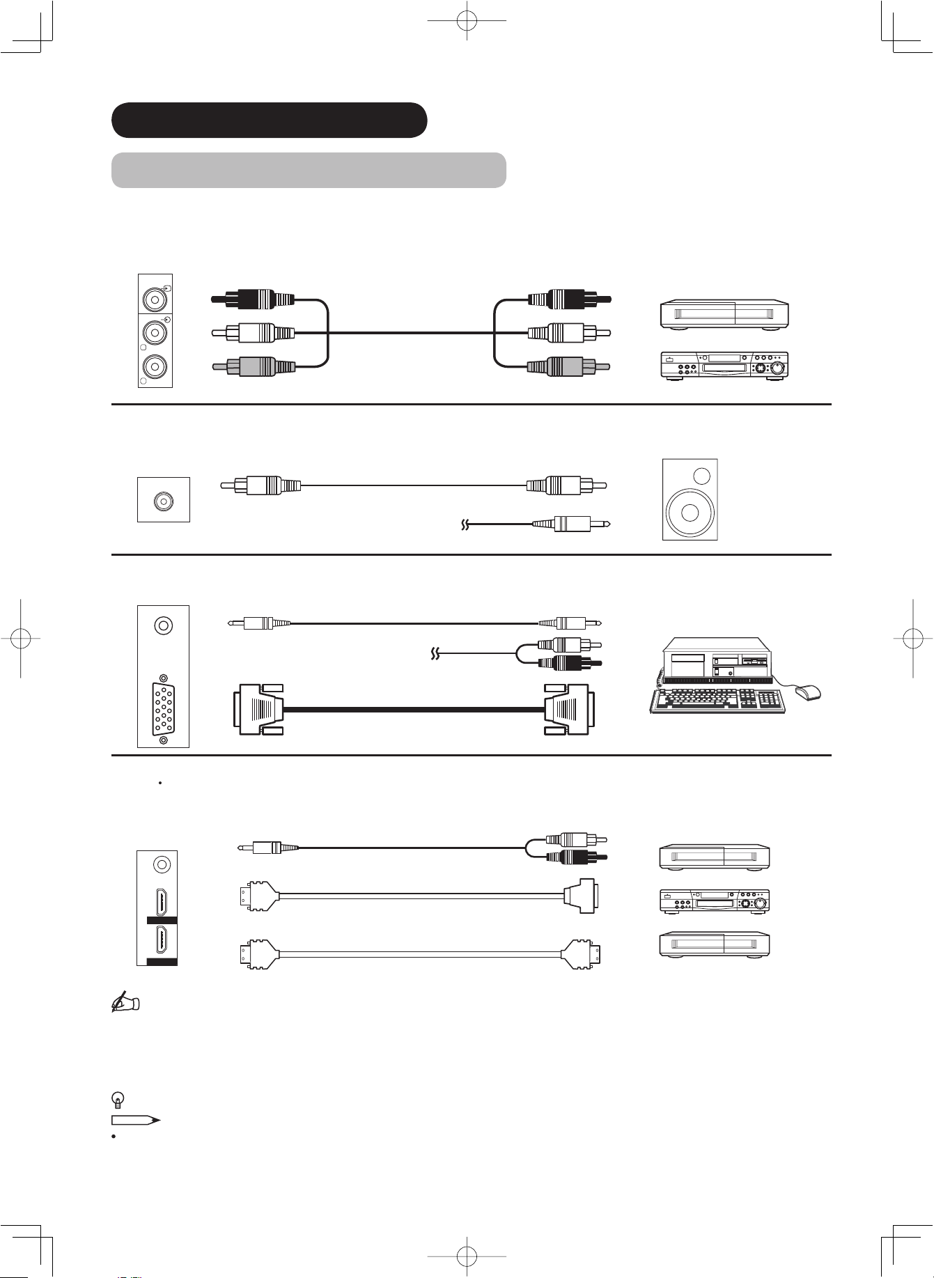
Connecting Procedure (continued)
Monitor Out can be used to display same image as main unit on another monitor.
When this output terminal is connected to an external monitor with a 75 Ohm terminal, the same image from
composite(AV1~5), or S-Video(AV3,5), or RF signal can be displayed to the external monitor.
[Example]
VCR
AUDIO
VIDEO
OUT IN
L
R
Sub Woofer terminal can bring the deep bass sound from the external speaker.
IN
WOOFER
OUT
SUB
[Example]
or
PC terminals (D-sub 15 pin + audio) is connected to PC, which allows Analog RGB signal.
IN OUT
(Mini Stereo plug)
or
DVD player
[Example]
HDMI 1 2
terminals can be connected to the devices with HDMI output, or if the external device has DVI output, this can be
available with HDMI-DVI conversion cable. In case of using the HDMI-DVI, connect to audio terminal besides HDMI.
[Example]
VCR
DVD player
Set-Top Box
HDMI2
HDMI1
IN OUT
(Mini Stereo plug)
(HDMI) (DVI)
or
(HDMI) (HDMI)
Information
HDMI(High Defi nition Multimedia Interface) is next-generation multimedia I/O interface. Only one cable is used to
transmit all video/audio/control signals, which creates easy connection.
Moreover, those digital signals can produce high quality data without any degradation.
You are provided two HDMI terminals, one of the most remarkable features.
If your external device has a HDMI terminal, HDMI connection is recommended for higher quality picture and sound.
NOTE
When both HDMI 1 and HDMI 2 terminals are connected to devices via HDMI-DVI conversion cable, HDMI 2 has
a priority over the audio terminal.
15
LD8800TA-8th-P1-P24.indd15LD8800TA-8th-P1-P24.indd15 2005/11/099:54:522005/11/099:54:52
Page 19
CONNECTION (continued)
Connecting Procedure (continued)
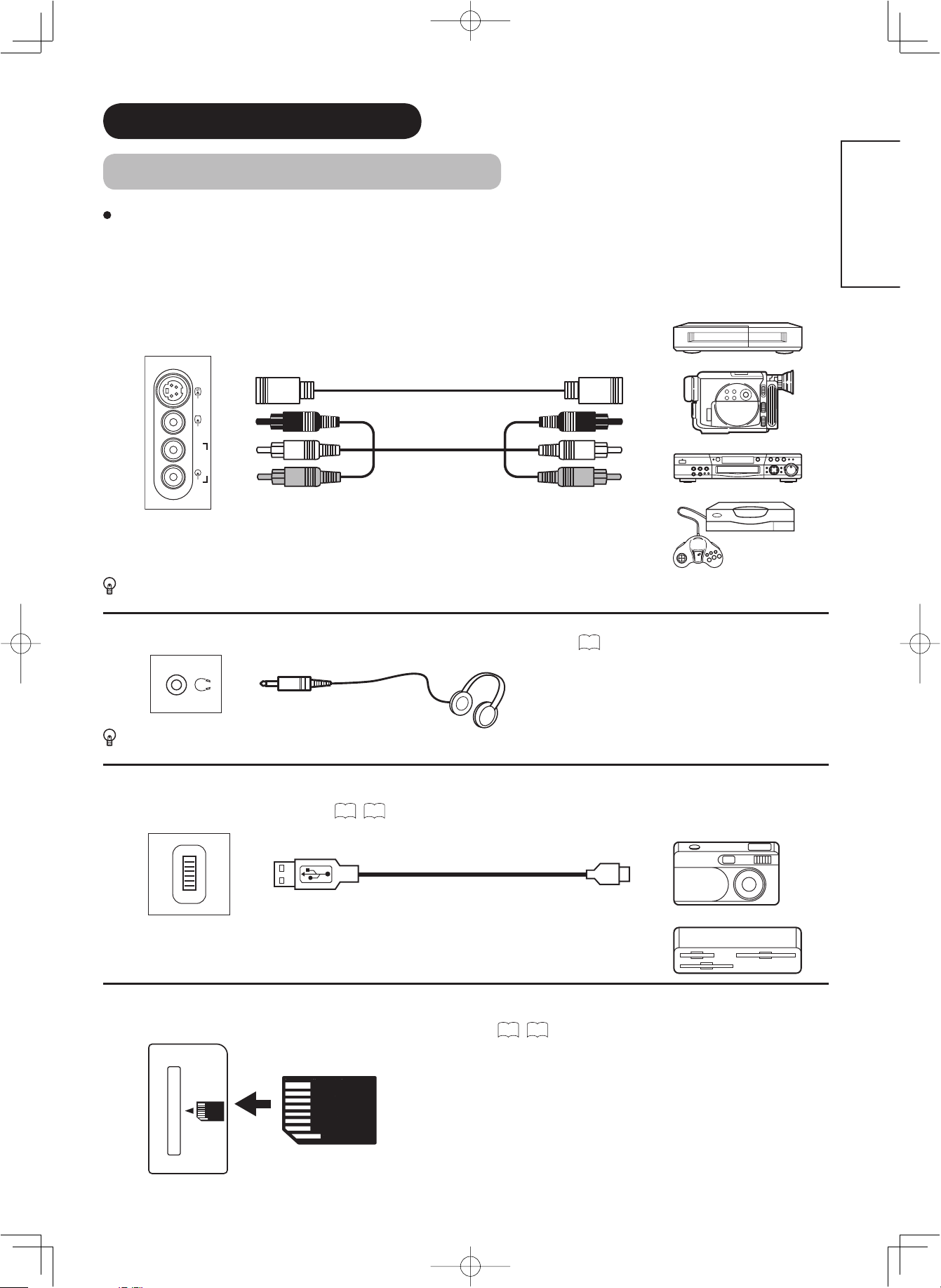
Terminals on Side
Since the following terminals are located on the side, it is very convenient to use the extra device on a temporary
basis after done the connections on the rear panel.
ENGLISH
AV5 can be connected to the equipment with an S-Video output and composite output.
IN OUT
VIDEO S-VIDEO
INPUT(AV5)
L/MONO
AUDIO
R
[Example]
VCR
Camcorder
DVD player
Home video game system
If your external device has a S-video terminal, S-VIDEO connection is recommended for higher quality picture.
Headphone The detail settings can be adjusted from Audio Menu on page 35.
(Mini Stereo plug)
The audio from the speaker will be muted when connecting the headphone to this terminal.
Photo Input terminal can be connected to digital still camera or USB card reader with USB cable. For details, refer
to the Photo Input function shown on
IN OUT
INPUT
PHOTO
45~50
.
[Example]
Digital Camera
USB Card reader
SD Memory Card slot can be used for the Photo Input function with the SD (or MMC) card memory containing
pictures. For details, refer to the Photo Input function shown on 45~50.
SD MEMORY
CARD
SD Card / MMC
PUSH-EJECT
16
LD8800TA-8th-P1-P24.indd16LD8800TA-8th-P1-P24.indd16 2005/11/099:54:522005/11/099:54:52
Page 20

CONNECTION (continued)
Connecting Procedure (continued)
4. Connecting the plug into the wall socket
Connect the Power Cord after completing all other connections.
(The type of plug is different from this drawing for some countries.)
CAUTION
Use only the Power Cord provided.
Do not use a power supply voltage other than that indicated(AC100-240V, 50/60Hz). It may cause fi re or electric shock.
For the LCD panel, a three-core power cord with a ground terminal is used for effi ciency protection. Always be sure to
connect the
use a power source converter plug, use an outlet with a ground terminal and screw down the ground line.
Ensure that both ends of power cord are easily accessible.
If you have to change the power cord, please use the certifi ed power cord that meets your region’s safety standard.
Power Cord
to a three-pronged grounded outlet and make sure that the cord is properly grounded. If you
Information
How to secure the cables.
After connecting all of the cables to the terminals, secure them with the band.
When you secure the cables, please be careful not to tighten too much.
INPUT(RGB)
AUDIO
PC
ANALOG RGB
INPUT(HDMI)
AUDIO
HDMI2
HDMI1
How to fasten the band:
To tighten
To loos en
Knob
INPUT
INPUT
INPUT
(AV2)
(AV1)
Y/VIDEO Y/VIDEO
PBPRPB
PR
AUDIO AUDIO AUDIO AUDIO AUDIO
L
L
MONO
C
C
RRRRR
A C
INPUT
MONO
OUTPUT
(AV4)
SUB
WOOFER
VIDEO
VIDEO
LL
MONO
C
(AV3)
S-VIDEO
VIDEO
L
MONO
C
ANT
WOW, SRS and symbol are trademarks of SRS Labs, Inc.
Licensed by BBE Sound, Inc. under USP5510752 and 5736897.
BBE and BBE symbol are registered trademarks of BBE Sound, Inc.
SERVICE USE ONLY
POWER SWIVEL
Pull the band in the
direction of the arrow.
Loosen the band by
pushing the knob in the
direction of the arrow.
With long band
17
LD8800TA-8th-P1-P24.indd17LD8800TA-8th-P1-P24.indd17 2005/11/099:54:572005/11/099:54:57
Page 21

BASIC OPERATION
Power On/Off
Now, turn On the main power of the unit. Make sure that the Power Cord
has plugged into the wall socket.
To turn On the power of the monitor:
ENGLISH
1. Press the Main Power switch on the monitor.
The Indicating Lamp will illuminates in Red (Standby mode).
2. Press Sub Power button either on the control panel or on the remote
control.
The color of the Indicating Lamp turns into Green, and the image will
display on the screen.
To turn Off the power of the monitor:
1. Press Sub Power button either on the control panel or on the remote
control.
The image disappears from the screen and the Indicating Lamp turns
into Red (Standby mode).
2. Press Main Power switch to completely turn Off the power of the unit.
The Indicating Lamp Status Check
Main Power switch (on the bottom surface)
Sub Power button
Sub Power button
SD MEMORY
CARD
PUSH-EJECT
P
P
OK
PH35814
Indicating Lamp
Status
Power Status Power Switch Status
Off Off Main power → Off
Red Standby mode
Green On
Orange Power Save mode*
Main power → On
Sub Power button → Off
Main power → On
Sub power button → On
Main power → On
Sub Power button → On
* About Power Save mode, see “Power Save Mode” and “When Following Messages Appear on the Screen” on
54 for details.
and
NOTE
If the image does not appear on the screen at all, or have any problem, see TROUBLESHOOTING on
54~56
52
. It
may help you to solve the problems.
You can turn ON the power only by pressing the Sub Power button during the Standby mode.
Do not switch the power On/Off repeatedly in a short period of time. It could cause malfunction.
To avoid sudden surges of electricity when the power comes back on, turn Off the main power of the unit before you
leave if there is a blackout during use of the unit.
18
LD8800TA-8th-P1-P24.indd18LD8800TA-8th-P1-P24.indd18 2005/11/099:54:582005/11/099:54:58
Page 22

BASIC OPERATION (continued)
First Time Setup
When you turn ON the TV for the fi rst time, your TV automatically leads to the settings
of “Language” and “Auto Tuning.”
1. The fi rst screen appeared will ask you to choose the language of your TV’s display.
2. Select the language you preferred from the list and press OK button.
3. Once selecting the language, “Auto Tuning” screen appears to start scanning
channels.
NOTE
If you want to change the setting after completing this fi rst time setup, press
MENU
button and set up individually. Refer to 21 22 .
Volume UP/DOWN
1. To increase the sound volume, press button on the remote control,
or Volume Up button on the control panel.
The Volume Indicator value on the screen will shift right.
2. To decrease the sound volume, press button on the
remote control or Volume Down button on the control panel.
The Volume Indicator value on the screen will shift left.
Language
ޓޓޓޓޓ
ޓޓޓޓޓޓᢥ
ޓޓޓޓޓ❥㜚ᢥ
ޓޓޓޓޓ
ޓޓޓޓޓ
ޓޓޓޓޓᣣᧄ⺆
Select Return Exit
Setup
Auto Tuning
Scanning Channel Number: 33
OK
Cancel
English
Руссkий
Cancel
Mute button
Mute
1. To mute the sound, press button on the remote control.
The sound of the unit is temporarily turned Off.
The color of the Volume Indicator will turn into magenta
while muting the volume.
2. To turn the sound back, press button again, or Volume Up button on
either remote control or the control panel.
The color of the Volume Indicator will turn back to green.
NOTE
You can decrease the volume by pressing button
while muted the volume.
Volume Up/Down button
SD MEMORY
CARD
PUSH-EJECT
P
Volume Up button
P
OK
Volume Down button
PH35814
Volume 15
The Volume Indicator
19
LD8800TA-8th-P1-P24.indd19LD8800TA-8th-P1-P24.indd19 2005/11/099:54:592005/11/099:54:59
Page 23

BASIC OPERATION (continued)
Input Switching to TV/AV1~5, HDMI, and RGB
By pressing Input Select button, you can switch the input.
To watch actual broadcast, press Input Select button on the control panel,
the numeric buttons or Channel Up / Down button on the remote control.
To display the image outputting from the external equipments
connected to each terminal (AV1~5, HDMI 1, 2, and RGB), select
corresponding mode.
1. Press Input Select buttons on the remote control.
2. The Input modes can be also switched by using Input Select button
on the control panel.
Each time this button is pressed, the screen displays corresponding
mode by following order.
TV AV1 AV2 AV3 AV4
AV5HDMI 1HDMI 2RGB
3. To directly go back to TV mode, pressing channel Up/Down buttons on
either remote control or the control panel.
Also, you can use the numeric buttons on the remote control.
SD MEMORY
PUSH-EJECT
PH35814
Input Select buttons
ENGLISH
Channel
Up/Down button
CARD
Channel Up button
P
P
Channel Down button
OK
Input Select
Input Signal Screen Display
The input signal status can be displayed on the screen by
pressing the
button
The display will go out in approximately 6 seconds.
TV
Off-timer
On-timer
VIDEO
Off-timer
On-timer
RGB
of the remote control.
-- -- Min.
OFF
-- -- : -- --
-- -- Min.
OFF
-- -- : -- --
ABCDE
AV1
Composite
RGB
H : 48.4kHz
V : 60.1 Hz
1
TV position
Name
Sound mode
Input mode
Signal mode
Input mode
Input horizontal frequency
Input vertical frequency
RECALL
button
Off-timer
On-timer
-- -- Min.
OFF
-- -- : -- --
20
LD8800TA-8th-P1-P24.indd20LD8800TA-8th-P1-P24.indd20 2005/11/099:55:082005/11/099:55:08
Page 24

MENU OPERATION
How to use the On-Screen Display (OSD) system
With the On-Screen Display system, you can access the various kinds of the features and functions in this product.
Picture
Basic Operation
1.
2. To select the item, press ▲ or ▼ buttons.
3. Press OK button to set your selection.
4. Use ▲ or ▼ buttons to choose the item on the MENU page.
5. Use ◄ or► buttons to adjust the item values or choose options.
MENU
Press
button on the remote control or Menu button on the control panel
of the unit. The Main Menu is displayed on the screen as shown on the right.
The selected item will be highlighted in Green.
The selected menu page will be displayed on the screen.
Press OK button to set your selection.
Press OK button to set your selection.
Menu button
Audio
Timer
Function
Setup
Language
Select OK Set
<Main Menu>
6. To exit from the menu, press
NOTE
MENU
button.
The OSD menu screen will be closed automatically when no operation has
been made for about one minute.
Menu button
Language Menu
Select the language from the list so that you can display the OSD menu in the selected language.
How to set Language
1. Enter the “Language” menu from the Main Menu.
2. Select the appropriate language with ▲ or ▼ button from the list.
The selected item will be highlighted in Green.
3. Press OK button to set your selection.
The black dot is marked inside of the circle when the selection is fi xed.
MENU
4. Press
button to exit from the entire OSD menu.
Language
ޓޓޓޓޓ
ޓޓޓޓޓޓᢥ
ޓޓޓޓޓ❥㜚ᢥ
ޓޓޓޓޓ
ޓޓޓޓޓ
ޓޓޓޓޓᣣᧄ⺆
Select Return Exit
English
Руссkий
SD MEMORY
PUSH-EJECT
PH35814
CARD
P
P
OK
21
LD8800TA-8th-P1-P24.indd21LD8800TA-8th-P1-P24.indd21 2005/11/099:55:082005/11/099:55:08
Page 25

MENU OPERATION (continued)
Setup Menu (TV mode)
With this menu, you can access various kinds of features relating to TV channel settings.
Auto Tuning
Setup
Auto Tuning
Manual Tuning
Fine Tuning
Sort
Teletext Language
Auto Off Off
Select OK Set Return
Selected Items Setup hint
Select the way to display the channels on the screen.
Position
Mode
Direct
The position numbers are displayed on the screen.
(1~199, AV00)
The channel number 0~99 are displayed as C , and the
channel number 100~199 are displayed as S .
Tune the local channels automatically.
Search
Position
Press OK button to start searching.
Press channel up (+)down(-) buttons to input position
number (1~199, AV00) or channel number (C or S ).
When Auto Tuning Mode is set to [position], search the
frequency by using ◄► buttons.
Frequency
When Auto Tuning Mode is set to [Direct], this function is
not available (grayed out).
ENGLISH
1. Move the cursor to the fi rst digit and select the letters
with ▲▼ buttons.
2. Move to the next digit with ► button.
Manual Tuning
Name
3. Press OK button again when you fi nish inputting all the
letters.
The selectable letters are as follows: “0”~”9”, “A”~”Z”, “+”,
“ ” (blank), “-” (displayed as blank), “,” (comma), and “.”
(period).
Auto
M
Sound
System
Select the sound system from 5 different modes.
BG
I
DK
Information
AV00 is useful when connecting to equipments such as VCR which its antenna terminal can output the specifi ed
channel frequency.
22
LD8800TA-8th-P1-P24.indd22LD8800TA-8th-P1-P24.indd22 2005/11/099:55:102005/11/099:55:10
Page 26

MENU OPERATION (continued)
Setup Menu (TV mode) (continued)
Selected Items Setup hint
Auto
Color
System
Manual Tuning
Fine Tuning -56~+56
Sort
Skip
NR
Antenna Att.
PAL
SECAM
NTSC4.43
NTSC3.58
Off
On
Off
On
Off
On
Select color system from 5 different modes.
It allows you to skip unregistered channels automatically
when you use channel up (+) down (-) buttons to select
channels.
Regarding the unavailable channels, this function will be
set to [On] automatically to skip.
The noise on the screen or interference could be reduced,
especially at the area of weak electric fi eld.
The noise on the screen or interference could be reduced
in case that the receiving airwaves are too strong.
The selection on this item is applied to all the channels.
► : Increase the frequency data for the main tuner.
◄ : Decrease the frequency data for the main tuner.
You can change the order of channels as follows.
1. Move the cursor to the Channel row you want to
change order and then, press OK button.
2. The color of the letters on the designated line will be
turned into green bracket and with [ ].
3. Move the designated row by using▲▼buttons.
4. Press OK button to fi x the position.
This function is not available (grayed out) when the Auto
Tuning Mode is set to [Direct].
Teletext Language
Auto Off
Select Teletext Language from 4 different categories (West
Europe, East Europe, Cyrillic, and Arabic) according to
the area.
Example:
West Europe : Asian countries where the Teletext
is broadcasting in English such as
Singapore, Australia, and Malaysia.
East Europe : Poland, Sweden, Hungary
Cyrillic : Russia
Arabic : Arab countries
When no airwave has been received and no operation
Off
has been made for 10minutes in TV mode, it turns to
On
standby mode automatically.
23
LD8800TA-8th-P1-P24.indd23LD8800TA-8th-P1-P24.indd23 2005/11/099:55:102005/11/099:55:10
Page 27

MENU OPERATION (continued)
Setup Menu (AV mode)
With this menu, you can select or adjust the condition of the input signals from each terminal.
System
Color
system
Setup
System System 1
Color System
Video Input
Select Set Return
Selected Items Setup hint
System 1
Do not change the original setting.
(System1: Europe/Asia, System2:North America)
System 2
Composite and S-video input only.
Auto
PAL
Select the color system depending on the input signal.
Generally, select [Auto].
In case that the input signal has too much noise, the
signal level is too low, or the operation is unstable in
[Auto], select the system according to the color system
of the input signal.
Composite and S-video input only.
AV1~AV5
System 1
System 2
SECAM
NTSC4.43
NTSC3.58
Auto
NTSC-M
PAL-M
ENGLISH
Video
Input
AV1, AV2
PAL-N
Auto
HDTV
SDTV/DVD
Select the colorimetry depending on the input signal.
Generally, select [Auto].
In case that the input signal has too much noise, the
signal level is too low, or the operation is unstable in
[Auto], set this to match the input signal.
Component Input only.
24
LD8800TA-8th-P1-P24.indd24LD8800TA-8th-P1-P24.indd24 2005/11/099:55:112005/11/099:55:11
Page 28

MENU OPERATION (continued)
Setup Menu (RGB mode)
With this menu, you can adjust the display condition of the image which is inputting from the RGB terminals.
By pressing ▼button at the bottom of the 1st Setup menu page, the 2nd Setup menu page will appear on the screen.
Setup
Auto Adjust Adjust
Horizontal Position 0
Vertical Position +31
Horizontal Clock –20
Clock Phase 10
Reset Reset
Select Return Exit
Selected Items Setup hint
Auto Adjust
Horizontal Position* -63~+63
Vertical Position* -31~+31
Setup
Input Level 0.7V
Frequency Display Off
WVGA Type Off
WXGA Mode Off
Vertical Filter On
Frequency Mode PC
Select Set Return
Adjust Horizontal Position, Vertical Position, Horizontal
Clock, and Clock Phase automatically.
Press OK button to start auto adjustment.
The message “Auto Adjusting” is displayed.
Depending on the type of the signal, there is a possibility
that the display may not be adjusted in its optimum
condition with this function. In that case, please adjust
each item manually.
Adjust the display position horizontally.
When the position exceeds the possible range, the
display color will turn into Magenta.
Adjust the display position vertically.
When the position exceeds the possible range, the
display color will turn into Magenta.
Horizontal Clock* -31~+31 Minimize the vertical stripes on the screen.
Minimize the blurring of the letters and stripes on horizon-
Clock Phase* 0~63
tal row.
Make sure to adjust Horizontal Clock fi rst before
adjusting Clock Phase.
Reset
Reset all the set values on this Menu page to original factory settings.
25
LD8800TA-8th-P25-P39.indd25LD8800TA-8th-P25-P39.indd25 2005/11/0815:43:182005/11/0815:43:18
Page 29

MENU OPERATION (continued)
Setup Menu (RGB mode) (continued)
Selected Items Setup hint
0.7V Normally, select [0.7V].
Input Level
Frequency Display
WVGA Type
WXGA Mode
Vertical Filter
Frequency Mode
1.0V
1280x768
1366x768
Movie
Select [1.0V] only when the whole display becomes too
white.
Off
Select whether indicating the PC signal frequency information on Input Signal Screen Display or not.
On
It allows you to switch display size to [Full] and [Real]. (See
Off
“Size Switching” on 39 for the details.)
This function is available only for WVGA signal.
On
Refer to “Recommended Signal List” on 59.
Off
This function is available only for WXGA signal.
Refer to “Recommended Signal List” on 59.
Off
Reduce the fl ickers on the screen when set to [On].
On
PC
This mode is not available (gray out).
ENGLISH
Information
The items indicated by “*” can be automatically stored the setting depending on the signal mode.
The signal mode is identifi ed by the Horizontal/Vertical frequency and the sync. signal polarity, which has almost
same values in all the above items might be regarded as the same signal.
The item “Auto Adjust” cannot be stored. Press
OK
to start auto adjustment as needed.
26
LD8800TA-8th-P25-P39.indd26LD8800TA-8th-P25-P39.indd26 2005/11/0815:45:252005/11/0815:45:25
Page 30

MENU OPERATION (continued)
Function Menu
This menu provides various ways to protect your panel, reduce power consumption, and set up utilizing the useful
functions, such as Freeze Mode and Photo Input.
Selected Items Setup hint
Black Side Panel
Video Power Save
Freeze Mode
Default Zoom
Picture Size
Function
Black Side Panel Off
Video Power Save Off
Freeze Mode Split
Default Zoom Panoramic
Picture Size 1
Reset Reset
Select Set Return
This can change the color of sidebars showing up in
Off
normal mode. (Off:gray, On:black)
It is recommended to set Off to reduce image retention.
Please note that it is not available while operating Photo
On
Input function.
During AV input, this helps to reduce power consumption
Off
when there is no video signal. In case of selecting AV
input terminal which does not have signal input, it changes
the power status to power save mode in AV1/AV2 and
On
standby mode in other AV input. (See 52 in details.)
Split
This is the useful function to watch the program in both
still and active pictures. (See 44 in details.)
Strobe
Split: half sized images
Strobe: thumbnail sized images
Panoramic
You can set the display size for TV / AV input screen
4:3
appearing fi rst when turning the main power On.
Full
In case that the image from TV signal (especially CATV) has
1
a blackened gap in either or both side during Panoramic
mode, select [2] so that it can make up for the gap.
This is not
2
This is not available except RF, composite, and
component (576i, 480i) input. (gray out)
available
Function
Background 1
Slide Effect 1
Slide Interval 5Sec.
Slide Music Off
Slide Mode 1
Reset Reset
Select Set Return
when displaying
“Cinema” size.
Reset
Each item on this menu screen can be restored to the
original factory settings by pressing
OK
button.
27
LD8800TA-8th-P25-P39.indd27LD8800TA-8th-P25-P39.indd27 2005/11/0815:45:252005/11/0815:45:25
Page 31

MENU OPERATION (continued)
Function Menu (continued)
Selected Items Setup hint
Background
Slide Effect
1
2
Off
1
2
This is available only for Photo Input function. Switch the
pattern of background. See details on 49.
This is available only for Photo Input function. You can
select the method of switching slides during slide show.
See details on 47.
ENGLISH
Slide Interval
Slide Music
Slide Mode
Reset
5Sec.
10Sec.
30Sec.
Off
This is available only for Photo Input function. You can
select the interval time for switching slides during slide
show. See details on 47.
This is available only for Photo Input function. You can
select the preferred Background Music during slide show.
1
See details on 47.
2
1
This is available only for Photo Input function. You can
select where to start the slide show. See details on 47.
2
Each item on this menu screen can be restored to the
original factory settings by pressing
OK
button.
28
LD8800TA-8th-P25-P39.indd28LD8800TA-8th-P25-P39.indd28 2005/11/0815:45:262005/11/0815:45:26
Page 32

MENU OPERATION (continued)
Picture Menu (TV/AV mode)
In this menu, you can make specifi c adjustments for the picture based on your preference.
By pressing ▼button at the bottom of each menu page, the next Picture menu page will appear on the screen.
Picture
Picture Mode Dynamic
Contrast +31
Brightness –31
Color 0
Sharpness +15
Tint 0
Color Temperature Normal
Contrast Mode Normal
Back Light +20
Reset Reset
Select OK Set Return
Selected Items Setup hint
Picture Mode
Contrast*
Picture Dynamic
YNR Off
CNR Off
Film Mode On
3D Comb Filter Off
LTI Off
CTI Off
Black Enhancement Off
Auto Color Off
Reset Reset
Select OK Set Return
Dynamic
You can make the better selection from 3 modes
depending on the lighting condition and intended use.
Natural
Dynamic: Suitable for the brighter conditions.
Natural : Suitable for the normal lighting condition.
Cinema
Cinema : Suitable for watching movie.
This adjusts the contrast to meet the lighting environment
by using ◄►.
The maximum value can be extended to [+40] by
-31 +31
(+32 +40)
pressing and holding ► button at [+31], which changes
the color between those numbers from green to
magenta. This is the special feature prepared for the
dark scene. At the normal condition, it is recommended
to set the value less than [+31] .
Picture Dynamic
Color Temp. Adjust
Color Management
Color Decoding
Select OK Set Return
Brightness* -31 +31
Color* -31 +31
Sharpness* -15 +15
Tint* -31 +31
Cool
Color Temperature*
Normal
Warm
Black/White
With this function, black is adjusted to change the overall
brightness by using ◄►.
It can adjust color density based on your preference by
using ◄►.
Preferred sharpness can be adjusted by pressing ◄
button for Softer image or ► button for Sharper image.
Pressing ◄ button enhances red and weakens green,
while pressing ► button weakens red and enhances
green. The setup hint is adjusting for the realistic skin
color. This is not available (grayed out) when receiving
PAL/SECAM signal.
You can select from 4 settings (default) depending on the
color condition with ◄► buttons.
29
LD8800TA-8th-P25-P39.indd29LD8800TA-8th-P25-P39.indd29 2005/11/0815:45:262005/11/0815:45:26
Page 33

MENU OPERATION (continued)
Picture Menu (TV/AV mode) (continued)
Selected Items Setup hint
It allows you to choose from 3 modes.
Dynamic: Sharpen the gradation to improve the contrast
feeling.
Normal: Reproduce as faithful gradation as possible.
Auto: Adjust to natural brightness without blurred white by
detecting the bright parts on images.
Contrast Mode*
Dynamic
Normal
Auto
ENGLISH
Back Light -20~+20
Reset
Off
YNR*
High
Off
CNR*
High
Off
Film Mode*
3D Comb Filter*
LTI*
CTI*
Black Enhancement*
Auto Color*
On
Off
Low
High
Off
Low
Middle
High
Off
Low
Middle
High
Off
Low
Middle
High
Off
On
Adjust the brightness of the Back Light for the maximum
visibility.
Each item on this menu screen can be restored to the
original factory settings by pressing
This is a noise reduction system for picture signal.Low
This is a noise reduction system for color signal.Low
On: Automatically identify if it is the movie fi lm and
faithfully reproduces the original fi lm images.
Off: Set to Off if the image does not look natural during
turning on.
This is available only when receiving NTSC/PAL
composite signal. This reduces the dot and color blurring
in minute scales so that it can reproduce purer color.
Adjusts the sharpness of the picture signals.
Adjusts the sharpness of the color signal.
Adjusts the black level compensation.
This monitors and adjusts the color to maintain constant
color levels. It also maintains natural fl esh tones while
preserving fi delity of background colors. This is available
only when receiving an NTSC composite and S.Video
signal.
OK
button.
Reset
LD8800TA-8th-P25-P39.indd30LD8800TA-8th-P25-P39.indd30 2005/11/0815:45:272005/11/0815:45:27
Each item on this menu screen can be restored to the
OK
original factory settings by pressing
button.
30
Page 34

MENU OPERATION (continued)
Picture Menu (TV/AV mode) (continued)
Selected Items Setup hint
Color Temp. Adjust**
Color Management**
Color Decoding
On
Off
On
Off
RGB/R/G/B
Amplitude
Red
Green
Blue
Cut off
Red
Green
Blue
Magenta
Red
Yellow
Green
Cyan
Blue
Red**
Green**
Color*
Tint*
On: When you want to set specifi c adjustments in each of
the 4 Color Temperature modes. You can adjust on
the amplitude and cut off. The settings refl ect on the
Color Temperature.
Amplitude: subdue the following colors on the brighter
parts.
Cut off : subdue the following colors on the darker
parts.
Off: Remains as default setting.
On: Turn On to adjust the balance of each colors
depending on the user’s preference. The settings
refl ect in each of the 4 Color Temperature modes.
Off: Remains as default setting.
This can adjust R/G/B level and tint to make the color
appear naturally for the user’s appearance.
First, select RGB (multiple color screen) or R/G/B(single
color screens) to check the color decoding effects while
adjusting. Then, you can adjust the level of color (red
and green), color intensity, and tint. Press OK to save
the setting. The settings refl ect in each of the 4 Color
Temperature modes.
Information
The items indicated by “*” can be stored the setting for each of inputs and picture modes (Dynamic/Natural/Cinema).
You can enjoy different setting depending on the selected input such as VCR in AV1.
In addition, the items indicated by “**” can be stored the setting for each of color temperature modes.
31
LD8800TA-8th-P25-P39.indd31LD8800TA-8th-P25-P39.indd31 2005/11/0815:45:272005/11/0815:45:27
Page 35

MENU OPERATION (continued)
Picture Menu (RGB mode)
In this menu, you can make specifi c adjustments for the RGB picture based on your preference.
Selected Items Setup hint
Contrast
-31~+31
(+32~+40)
Brightness -31~+31
Color -31~+31
Picture
Contrast : +31
Brightness : –31
Color : 0
Tint : +31
Picture Enhancement
Color Temperature : Normal
Color Temp. Adjust
Back Light : +20
Reset Reset
Select OK Set Return
: Off
This adjusts the contrast to meet the lighting environment
by using ◄►.
The maximum value can be extended to [+40] by
pressing and holding ► button at [+31], which changes
the color between those numbers from green to
magenta. This is the special feature prepared for the
dark scene. At normal condition, it is recommended to
set the value less than [+31] .
With this function, black is adjusted to change the overall
brightness by using ◄►.
It can adjust color density based on your preference by
using ◄►.
ENGLISH
Tint -15~+15
Off
Low
Picture Enhancement
Middle
High
Cool
Normal
Color Temperature
Warm
Black/White
Pressing ◄ button enhances red and weakens green,
while pressing ► button weakens red and enhances
green. The setup hint is adjusting for the realistic skin
color.
You can select the preferred sharpness on detailed parts.
You can select from 4 settings (default) depending on the
lighting condition with ◄► buttons.
32
LD8800TA-8th-P25-P39.indd32LD8800TA-8th-P25-P39.indd32 2005/11/0815:45:282005/11/0815:45:28
Page 36

MENU OPERATION (continued)
Picture menu (RGB mode) (continued)
Selected Items Setup hint
Amplitude
Red
Green
Color Temp. Adjust.**
Back Light -20~+20
Reset
Information
There is a useful function to automatically store the setting on menu in almost every item so that you do not have to
reset every time. Furthermore, the following items can be stored more specifi cally.
In addition, the items indicated by “**” can be stored the setting for each of color temperature modes.
On
Off
Each item on this menu screen can be restored to the original factory settings
by pressing OK button.
Blue
Cut off
Red
Green
Blue
On: When you want to set specifi c adjustments in each of
the 4 Color Temperature modes. You can adjust on
the amplitude and cut off. The settings refl ect on the
Color Temperature.
Amplitude: subdue the following colors on the brighter
parts.
Cut off : subdue the following colors on the darker
parts.
Off: Remains as default setting.
Adjust the brightness of the Back Light for the maximum
visibility.
33
LD8800TA-8th-P25-P39.indd33LD8800TA-8th-P25-P39.indd33 2005/11/0815:45:282005/11/0815:45:28
Page 37

MENU OPERATION (continued)
Audio Menu
With this menu, you can adjust and customize the audio condition as you like.
You can move on to the next menu screen by pressing ▼button at the bottom.
Audio
Audio Mode
Treble : +15
Bass : –15
Balance : 0
SRS
TruBass : Low
BBE : Low
Perfect Volume : Off
Internal Speaker : On
Reset Reset
Select Set Return
Selected Items Setup hint
: Movie
LR
: Normal
Audio
Head Phone Volume
Head Phone Select : A/B
Select Adjust Return
: +20
ENGLISH
Movie
Music
Audio Mode
Speech
Favorite
You can select the most suitable sound condition from 4
alternatives according to the contents.
If you want to adjust each item value based on your
preference, select “Favorite”.
Treble** -15~+15 Adjust the Treble of the sound.
Bass** -15~+15 Adjust the Bass of the sound.
Balance -10~+10
Adjust the balance of the sound comes out from right and
left side of the speakers.
Off
SRS
Normal
This system gives you the dynamic 3D sound. Select it
depending on your preference.
Wide
Off
TruBass
Low
TruBass gives you the enchanced bass sound.
Select it depending on your preference.
High
Off
BBE High Defi nition Sound restores clarity and presence
BBE
Low
High
for better speech intelligibility and musical realism.
Select it depending on your preference.
Off
Perfect Volume**
It will automatically adjust the volume to its average level
each time you change the channel.
On
This needs to be switched to Off when you want to take
Off
Internal Speaker
Reset
audio from external epuipment.
It normally sets to On when you operate this monitor with
On
the equipped speaker.
Reset all the set values on this Menu Page to the original
factory settings.
34
LD8800TA-8th-P25-P39.indd34LD8800TA-8th-P25-P39.indd34 2005/11/0815:45:282005/11/0815:45:28
Page 38

MENU OPERATION (continued)
Audio Menu (continued)
Selected Items Setup hint
It allows you to adjust the volume of the headphone. The
Headphone Volume 0~63
A/B
Headphone Select
NOTE
The headphone is NOT available when the image from the RGB or Photo Input is on the screen.
sound from the speaker will automatically set to MUTE
when the headphone is connected to the terminal.
Select the either side of the display that you want to hear
the sound with headphone during 2-picture mode.
(See “Multi Picture Mode” on 41)
A/B : You can select either side A (left side) or side
B (right side) which the sound comes into the
headphone. The speaker icon will be displayed on
the side you select.
B : You will hear the sound only from the side B (right
B
side) of the display.
Information
There is a useful function to automatically store the setting on menu in almost every item so that you do not have to
reset every time. Furthermore, the following items can be stored more specifi cally.
The items indicated by “**” can be stored the setting for each of Audio Mode.
Timer Menu
This allows your monitor to turn Off (Standby mode) or On at set time automatically, which you may fi nd useful.
Off Timer
Timer
Off Timer
On Timer
Select Adjust Return
Selected Items Setup hint
--Min.
30Min.
60Min.
This function automatically sets the power to Standby
mode when the selected time period has elapsed.
90Min.
: 30Min.
: -- : --
120Min.
This function automatically sets the power from standby
On Timer --:--
mode to On when the specifi ed time period has elapsed.
Input the desired time within the range of 00:00 to 11:59
by using ▲▼ button on the remote control.
35
LD8800TA-8th-P25-P39.indd35LD8800TA-8th-P25-P39.indd35 2005/11/0815:45:302005/11/0815:45:30
Page 39

FUNCTION
Power Swivel
With the Desktop stand (included for 32LD8800TA, optional for 37LD8800TA), you can adjust the angle of the
monitor side to side by pressing
1. Press
SWIVEL
button on the remote control.
SWIVEL
button on the remote control.
The Swivel Display (as shown in the fi gure on the right) will appear on the
screen.
2. Adjust the angle of the monitor with ◄ ►keys while Swivel Display is on
the screen.
The monitor will be able to move ±30 degrees to each side.
SWIVEL
CAUTION
button
When you use the Power Swivel function, make sure that the Power Cord, cord
or chain connected to the wall is loose enough to operate the Swivel function
securely.
Do not put hands or faces near the monitor while operating the Swivel. It could
Swivel
cause personal injury. Beware especially when small children are around the
monitor.
NOTE
The Swivel Display
Slack
If the stand cable is not connected to the unit, the message “Not Available”
will appear on the screen.
The Swivel Display will automatically disappear when no operation has
been made for about 6 seconds.
ENGLISH
30°
30°
CAUTION
Do not push the panel with your hands while operating the Swivel. It could damage the panel and/or stand.
Do not allow children to play or hang on the TV. These actions may tip it over, causing personal injury.
Do not swing the monitor back and forth.
Do not place any fragile objects around the monitor. The monitor would hit the object(s) during the Swivel
operation and could cause the breakage of the objects and/or the stand.
To operate the Swivel function correctly, place the monitor on the stable surface.
When you use the unit as wall-mounting, disconnect the stand cable from the monitor before installation.
Information
About Swivel terminal connection
To connect the Desktop stand to the unit
Connect the designated stand cable to the Swivel
terminal on the rear side of
the unit.
POWER SWIVEL
To disconnect the stand from the unit.
Before detach the stand from the unit, make sure to
disconnect the stand cable
from the Swivel terminal on
L
E
IV
W
S
R
E
W
O
P
the rear side of the unit.
CAUTION
When you install the Desktop stand, follow the Instructions of the Manual included with the stand.
Turn Off the Main Power of the monitor when connecting or disconnecting the stand cable to the unit.
36
LD8800TA-8th-P25-P39.indd36LD8800TA-8th-P25-P39.indd36 2005/11/0815:45:322005/11/0815:45:32
Page 40

FUNCTION (continued)
About Teletext
What is “Teletext”
Teletext is the written information services provided by each TV channel.
Most TV channels provide information via Teletext such as:
Page Number
TV program schedule
Weather forecasts
Sports results
Newsfl ash
How to operate the Teletext
You can display the Teletext simply by pressing the remote control buttons.
NOTE
Select Teletext language from Setup Menu shown on 23 .
Link pages
11 : 37 : 56
Red Green Yellow Blue
Operation Press
To activate Teletext mode.
To exit from the Teletext mode.
To split the screen into two and watch both Teletext information
and actual broadcast at the same time.
Press again to watch Teletext on a single screen.
[TextTV+Text]
To display Index page.
To access Subtitle service directly (if the channel has the Subtitle
service broadcasting).
To display Hidden text.
ex. The answers of the Quiz or the Game page.
Press again to close the revealed answer.
To return to actual broadcast temporarily while searching for the
Teletext page you request.
When the search is done, the designated page # will be displayed
on the upper left of the screen.
Press again to return to Teletext page.
To access the link pages which are displayed at the bottom of the page.
(Select the buttons corresponding to the colors of the letters on screen.)
[TVText]
[Index]
[Subtitle]
?
[Reveal]
X
[Cancel]
[Color]
To hold the text picture.
2-4-12
[Hold]
Information
Each time the
Some Teletext pages do not display Link Pages at the bottom of the screen. Press
button is pressed, the screen will be switched from double screen to signal screen.
button to display them.
37
LD8800TA-8th-P25-P39.indd37LD8800TA-8th-P25-P39.indd37 2005/11/0815:45:332005/11/0815:45:33
Page 41

FUNCTION (continued)
Size Switching
Each time button of the remote control is pressed, the screen display size is
switched in sequence, and the status will be displayed at the bottom of the screen.
TV/AV signal input
ZOOM button
TV/AV1/AV2/AV3/AV4/AV5/HDMI1/HDMI2
4:3 Panoramic Zoom
CinemaFull
You can display the image at optimum condition by selecting display size depending on the current output image as
shown below.
Current Output
Image
(Input Signal)
Display Size To display suitable screen as follows.
4:3
Play a 4:3 image on screen faithfully. Blanking occurs on both sides.
ENGLISH
(4:3 Signal)
(Vista)
(Cinema)
(Squeeze)
Information
Aspect ratio represents horizontal : vertical ratio on screen.
For example, vista image is 16:9 in 4:3 image.
Position Adjustment
Vertical picture position can be adjusted for Panoramic, Zoom, and Cinema mode
as follows.
1. Press ▲▼buttons while operating the picture size display.
2. “Position” display will appear.
3. Adjust the position by ▲▼buttons.
Adjustment range of each picture size are as shown below.
Panoramic: -12 to+12 (The position cannot be adjusted in Panoramic 2 mode)
Zoom and Cinema: -31 to+ 31
*When 1080i/60 component signal is received, it can be adjusted only 0 to +1.
Panoramic
Zoom
Cinema
Full
Play a 4:3 image which enlarges horizontal and vertical size of the
middle in equal scales, and displays both sides appearing much wider.
Play a 16:9 image in 4:3 image (Vista size) faithfully.
*In some case, slight blanking may remain at the top and bottom.
Play a 21:9 image in 4:3 image (Cinema size) expanding vertically.
*In some case, slight blanking may remain at the top and bottom.
Play a 4:3 image faithfully in the standard vertical size and
horizontally squeezed.
16(or 21)
9163
4
9
Position + 31
Press▲
Vertical Size Adjustment at Panoramic Mode
While displaying a picture at Panoramic mode, the mode can be switched further between Panoramic 1 and Panoramic 2
with ◄ ►buttons on the remote control. By selecting Panoramic 2, the vertical size is scaled down so that you can
see the whole image without blanking.
LD8800TA-8th-P25-P39.indd38LD8800TA-8th-P25-P39.indd38 2005/11/0815:45:362005/11/0815:45:36
Position - 31
Press▼
38
Page 42

FUNCTION (continued)
Size Switching (continued)
TV/AV signal input
CAUTION
Using a wide-screen monitor
This monitor has a screen mode selection feature. If an incompatible screen mode is selected to play certain
software, such as a TV program, the image would appear different form the original. Take this into consideration
when making screen mode choices.
Use of the wide feature displaying enlarged pictures in coffee shops, hotel and other establishments for
commercial or public viewing purposes could infringe on the copyright holder’s right protected by Copyright Law.
When a normal 4:3 image (not wide screen) is displayed over the entire screen in the Panoramic mode, the
peripheral image may disappear partly and/or appear distorted in some cases. Use 4:3 mode to view the image
refl ecting original intention.
RGB signal input
You can select suitable size depending on the resolution.
Normal Full Zoom1
*
Zoom3
Zoom2Real
* Real mode gives the image with same shapes as
that of computer monitor.
This mode is only available for VGA(640x480) to
WXGA(1280x768).
Display Area Selection Diagram
Resolution Full display Circular display
Display Full Normal Real* Zoom1 Zoom2 Zoom3
640 X 480 (VGA)
800 X 600 (SVGA)
1024 X 768 (XGA)
1280 X 1024 (SXGA)
1600 X 1200 (UXGA)
It has been performed processes such as compression (thinning) and enlargement for the above signal display. It
may affect fl icker to become noticeable on Zoom (1~3) depending on the display contents. To reduce this fl icker, turn
“Vertical Filter” On from “Setup Menu” (26).
39
LD8800TA-8th-P25-P39.indd39LD8800TA-8th-P25-P39.indd39 2005/11/0815:45:382005/11/0815:45:38
Page 43

FUNCTION (continued)
Multi Picture Mode
With this feature, you can watch different channels simultaneously on one screen in several ways.
As for the available signals, please refer to "Recommended Signal List" on
This function is NOT available in HDMI input.
To activate Multi Picture mode in either TV, AV, and RGB mode,
press on the remote control.
2-picture mode
You can watch two different pictures side by side.
This mode is available in both TV mode and AV mode (AV1~5 Input).
Control on the side with Speaker Icon
Audio is output from the selected picture with the speaker icon.
You can switch the Input modes (TV and AV1~5) or change
channels only on the side with Speaker icon.
60
.
ENGLISH
1. To shift the speaker icon, press ◄ ►button.
The speaker icon will be shifted from A to B back-and-forth.
+
2. To change the channel on the selected picture, press
3. To select the Input mode on the selected picture, press Input Select buttons on
the remote control.
NOTE
In TV mode, you cannot select the same channels on both sides simultaneously.
You cannot select the same AV input on both sides simultaneously.
The message “Not Available” will be appeared on the screen when the
combinations of the Input modes are not acceptable.
(See the Table below for details.)
P
.
-
The selected picture with speaker icon
Table: Mix-and –Match of the Input Modes
Side B
Side A
TV ○*○○○○○
AV1 ○×○○○○
TV AV1 AV2 AV3 AV4 AV5
AV15
AB
AV2 ○○×○○○
AV3 ○○○×○○
AV4 ○○○○×○
AV5 ○○○○○×
*You cannot select the same TV channels on both sides simultaneously.
40
LD8800TA-8th-P40-P50.indd40LD8800TA-8th-P40-P50.indd40 2005/11/1017:55:302005/11/1017:55:30
Page 44

FUNCTION (continued)
Multi Picture Mode (continued)
2-picture mode (continued)
4. To switch to 4-picture mode, press
2-4-12
once.
The 4-picture mode is displayed on the screen.
NOTE
Each time
is pressed, the picture mode will be switched by following order.
2-4-12
AV1
AV2
2-Picture 2-Picture (1080i)* 4-Picture 12-Picture (TV mode only)
When receiving 1080i format of component signal, there is a mode (2-Picture(1080i))
*
which sub-screen is displayed inside of the large screen (Main-screen). Please
note that you cannot display the picture with component signal on Sub-screen.
[2-Picture (1080i) Mode]
5. To EXIT from the Multi Picture mode, press button.
Next time you press to activate the Multi Picture mode, it will start from 2-picture mode.
4-picture mode
You can watch 4 different pictures from live broadcasts and/or the external equipments at the same time.
(Subscreen)
NOTE
The audio comes out ONLY from side A.
You can change the channels or change Input modes on the side with ▼ (red triangle) mark.
1. To switch the ▼ location
The selected picture with red triangle mark
Press ◄►buttons on the remote control.
The ▼ mark will shift to side A and side B back-and -forth.
2. To change the channel
Make sure that ▼mark is located on the side you want to make changes.
+
P
Side A: Press
to select channels.
-
Side B: Select the frame (B1~B3) that you want to make changes
with ▲▼buttons. The selected frame will be highlighted in green.
+
Press
P
buttons to select channels.
-
3. To change Input mode
A
B1 8
5
B2 6
B3 11
Make sure that ▼mark is located on the side you want to make changes.
Side A: Press Input Select buttons on the remote control.
Side B: Select the frame (B1~B3) that you want to make changes
with ▲▼buttons. The selected frame will be highlighted in green.
Press Input Select buttons on the remote control.
41
LD8800TA-8th-P40-P50.indd41LD8800TA-8th-P40-P50.indd41 2005/11/1017:56:192005/11/1017:56:19
Page 45

FUNCTION (continued)
Multi Picture Mode (continued)
4-picture mode (continued)
NOTE
You cannot display the picture with Component signal on Side B screens.
4. To EXIT from Multi Picture mode, press button.
Next time you press to activate the Multi Picture mode, it will start from 4-picture mode.
5. To switch to 12-picture mode, press
The 12-picture mode is displayed on the screen.
12-picture mode
You can check 12 different live broadcast channels on one screen.
The channels that are preset in advance (up to 200 channels) will
automatically appear in certain intervals.
2-4-12
button.
1432
ENGLISH
NOTE
5876
This mode is available only in TV mode.
9121110
1. To EXIT from the Multi Picture mode, press .
Next time you press to activate the Multi Picture Mode, it will start from 12-picture mode.
2. When you press
in this sequence, the 2-picture mode will be displayed.
2-4-12
42
LD8800TA-8th-P40-P50.indd42LD8800TA-8th-P40-P50.indd42 2005/11/1017:56:202005/11/1017:56:20
Page 46

FUNCTION (continued)
Multi Picture Mode (continued)
Activate the Multi Picture Mode in RGB Mode
When you activate the Multi Picture mode in RGB Input, the picture will be displayed at the mode which the Subscreen is displayed inside of the large screen (Main-screen).
To activate Multi Picture mode, press on the remote control.
The speaker icon indicates the following.
The audio sounds can be heard on the side with the speaker icon.
When the speaker icon is on the Sub-screen
Change channels.
Switch the Input modes (TV and AV1~5) on the Sub-screen. (Main-screen is only for RGB Input.)
1. To shift the speaker icon , press ◄►buttons.
Input mode indication
The speaker icon will be displayed in front of the Input mode indication.
Main-screen (upper)
Sub screen (lower)
2. To change the channel of the Sub-screen.
Make sure that mark is located on the Sub-screen.
+
Press
P
to select channels.
-
RGB
AV1
3. To change the Input mode of the Sub-screen.
Make sure that the speaker icon is located next to the Input mode
indication of the Sub-screen (lower).
Press Input Select buttons on the remote control.
(AV1~5 are available)
(Subscreen)
4. To change the location of the Sub-screen.
Press ▲▼buttons. The Sub-screen will move up and down.
5. To exit from the Multi Picture mode, press button.
NOTE
When operating Multi Picture mode, the “Power Save mode” is not available even though the Horizontal/Vertical
Sync. Signal (or any kind of Video signal) has not input for certain period of time.
43
LD8800TA-8th-P40-P50.indd43LD8800TA-8th-P40-P50.indd43 2005/11/1017:56:212005/11/1017:56:21
Page 47

FUNCTION (continued)
Picture Freezing
This is the useful function utilizing the characteristics of freezing picture
effectively. By pressing
anytime you like. Press it again to return to normal picture.
There are two types of freeze mode as usage. These are possible to select at
the “Freeze Mode” from Function Menu.(27)
button, you can change to freeze mode easily
2-4-12
FREEZE button
ENGLISH
[Split]
Split:
It displays 2 pictures from the same source. One is active (left), while the other
is still picture (right). This is very useful in order to avoid missing or take note
necessary information, such as ingredients in cooking.
Strobe:
It displays 12 pictures from the same source. 11 of them are still, while the last
picture is active. This can be used to check such movement as swinging of
golf club and baseball bat.
This function is also available in AV input mode besides TV mode. Refer to the
table as shown in “Recommended Signal List” on 60.
AA
[Strobe]
1
2
3
5
6
7
9
10
11
I
4
8
12
ACTIVE
44
LD8800TA-8th-P40-P50.indd44LD8800TA-8th-P40-P50.indd44 2005/11/1017:56:212005/11/1017:56:21
Page 48

FUNCTION (continued)
Photo Input Function
With this Photo Input function, you can enjoy watching Photos from such devices as
Digital Still Camera and SD card on monitor along with useful features such as Slide
Show with Background Music and Movie picture.
Operating the Photo Input
1. Before operating this function, make sure to turn the power OFF /Standby.
2.
Prepare the DSC (Digital Still Camera) / USB card reader/ SD card or MMC as follows.
Digital Still Camera : Set up with reference to the content about
“connecting to PC” in the user manual of DSC.
USB Card Reader : Insert only one memory card.
SD Card / MMC : Ensure the card is inserted in the correct direction as
indicated near the slot.
3. Connect the USB cable to the input terminal as shown (Right side), or insert the
SD card /MMC into the slot (Left side).
4.
Turn ON the TV after the USB cable is connected or the SD card / MMC is inserted.
5. Press button on the remote control to activate Photo Input mode.
(Then, turn ON the DSC. Refer to the user manual of your DSC for the timing.)
6. Each time button is pressed, you can switch the mode as follows.
Photo Movie Normal Screen
Left Side
SD MEMORY
CARD
PUSH-EJECT
P
P
OK
SD Card/MMC
PH35826
INPUT(AV5)
VIDEO S-VIDEO
L/MONO
AUDIO
R
USB cable
Right Side
Digital Camera
USB Card Reader
PH35814
Rear Panel (Left side and Right side)
NOTE
Do not insert SD Card/MMC and USB cable at the same time.
Do not insert anything other than SD Card/MMC into the slot. It could cause malfuction or damage to the slot.
45
LD8800TA-8th-P40-P50.indd45LD8800TA-8th-P40-P50.indd45 2005/11/1017:56:222005/11/1017:56:22
Page 49

Do not allow children to play around the slot.
FUNCTION (continued)
Photo Input Function (continued)
Displaying Still Picture in Photo Mode
Thumbnail-Size Image (Index) to Full-Size Image
4
3
2
1
8
7
6
5
12
11
10
9
16
15
14
13
P
P
18
17
22
21
26
25
30
29
Photo Index (1st Page). Photo Index (2nd Page)
Move to next page.
OK
20
19
24
23
28
27
32
31
20
19
18
17
24
23
22
21
28
27
26
25
32
31
30
29
Photo Index (2nd Page)
Select the file.
ENGLISH
No. 23
28/05/03
1600x1200
OK
Full size
File#23 is displayed.
File#24 is displayed.
No. 24
28/05/03
1600x1200
Full size
When you enter the Photo Index mode, the icon appears as the indication.
You can also select the preferred fi le in both Thumbnail-size and Full-size image by inputting the fi le directly with
numeric buttons of remote control.
Rotation Function
-ROTATE-
?
A
Photo Index (2nd Page). Rotating a thumbnail
image to 90°.
OK
No. 23
A
28/05/03
1600x1200
A
-ROTATE-
?
A
Rotating a full size
image to 90°.
Each time
Full size
-ROTATE-
?
button is pressed, the picture is rotated in the sequence of the following.
File#23 is displayed.
90° 180° 270° 0°
46
LD8800TA-8th-P40-P50.indd46LD8800TA-8th-P40-P50.indd46 2005/11/1017:56:242005/11/1017:56:24
Page 50

FUNCTION (continued)
Photo Input Function (continued)
Displaying Still Picture in Photo Mode (continued)
Slide Show Function
SLIDE SHOW
20
19
18
17
24
23
22
21
28
27
26
25
32
31
30
29
Photo Index (2nd Page)
Select the file.
Slide Show begins.* Slide Show is paused.
No. 23
28/05/03
1600x1200
OK
OK Start
*
You can select where to start Slide Show. See “Slide Mode
*You can also start the slide show when displaying the selected full
size image, press SLIDE SHOW button by pressing
in
”
SLIDE SHOW
the table 1.
button.
If the pause is left for more than a minute, the slide show restarts automatically.
If you stop the slide show halfway, the photo index page selects the fi le in which you stopped.
You can make specifi c adjustment on “Slide Effect / Slide Interval / Slide Music / Slide Mode” from “Function
Menu (2nd page)”. While operating Photo Input function, you can jump to there by pressing
MENU
button. Press it
again to return to the Photo Input page. (Refer to Table 1 as below.)
NOTE
Contrast will decrease automatically to reduce power consumption if stationary images such as
still photos are left on the screen for more than 3 minutes. Please note that it is not malfunction.
Table 1. Slide Show Adjustment
Function Menu Selection Description
Select Slide Switching Method.
Slide Effect Off→1→2
Off: No effect
1: Fade In/Out effect
2: Wipe effect
Slide Interval 5Sec.→10Sec.→30Sec. Select preferred interval times.
Slide Music Off→1→2
Slide Mode 1→2
47
Select the Background Music.
Off: No sound.
1: Slow tempo music.
2: Up tempo music.
Select starting point of slide show.
1: Start from the selected fi le.
2: Start from 1
st
fi le.
LD8800TA-8th-P40-P50.indd47LD8800TA-8th-P40-P50.indd47 2005/11/1017:56:252005/11/1017:56:25
Page 51

FUNCTION (continued)
Photo Input Function (continued)
Displaying Movie Picture in Movie Mode
Thumbnail-Size Image (Index) to Full-Size Image:
17
1
2
3
4
5
6
7
8
9
10
11
12
13
14
15
16
Photo Index (1st Page). Movie Index (2nd Page). Movie Index (2nd Page)
1
2
3
4
5
6
7
8
9
10
11
12
13
14
15
16
Movie Index (1st Page).
2
2
18
21
22
25
26
29
30
ENGLISH
17
18
19
19
20
21
23
24
27
31
or*5
28
32
22
25
26
29
30
Select the file.
20
23
24
27
28
31
32
OK
or
Movie starts.
or*1
or *2
Operate the Movie
with remote control
or
or *3
After completing the
current movie, the
keys or Movie OSD.
*1: Press ▲▼ or
*2: Press
*3: For the Previous button on remote control or OSD, pressing it once starts over the current movie. By
pressing it again within 2 seconds after that, you can return to the previous movie.
*4: When it moves on the unsupported fi le, it automatically returns to the Index.
*5:
You can also select the Thumbnail-Size image by inputting fi le # with numeric buttons of remote control.
button to display the operation OSD.
button in remote control or
[Operating the Movie]
You can use the following control key to operate the movie.
Fast-
forward
RGB
Rewind Pause Next Previous Zoom
HDMI2
HDMI1
Remote
Control
OSD
Play
AV4
Stop
AV3
19
18
17
23
22
21
27
26
25
31
30
29
After completing all
of the movie files, it
next Movie starts
automatically.
button (OSD) to exit from the OSD display.
3
*
automatically returns
to the Index.
Slow
Play
Exit
20
24
28
32
*4
The movie OSD contains the fi le information and control keys as below.
The following indications might appear in Movie Operation OSD.
: The movie does not have sound, or this function does not support only the sound of movie.
: This function does not support the movie.
NOTE
With
button on the remote control, you can switch the size of movie display between normal and double in full size mode.
In case of displaying movie pictures,
1) If your DSC supports SD card/MMC, insert the card to the monitor directly rather than USB.
2) If your DSC is PictBridge-compatible and has a function to switch between PTP and Mass Storage connection,
change your setting to Mass Storage and then connect to Photo Input terminal so that it can be available on
both Still and Movie pictures. PTP connection can display still pictures but not movie pictures.
3)
If your DSC does not support SD card / MMC or Mass Storage connection, use USB card reader to connect
with Photo Input terminal. Please note that we do not guarantee all DSC can make either or both Mass Storage
and USB card reader connection.
Comparing to movie pictures through SD card/MMC, the movie pictures using USB might have lower
performance such as dropping frames.
48
LD8800TA-8th-P40-P50.indd48LD8800TA-8th-P40-P50.indd48 2005/11/1017:56:272005/11/1017:56:27
Page 52

FUNCTION (continued)
Photo Input Function (continued)
Other
You can select the background pattern on “Background” from “Function Menu.”
Function Menu Selection Description
Select preferred background pattern.
Background 1→2
Press
The fi le information is displayed by pressing
button whenever you want to return from full size image to index.
button.
1: Striped texture of gray
2: Green checked pattern
Thumbnail-Size Image Full-Size Image (Still) Full-Size Image (Movie)*
* The size of the image depends
on the resolution for the image.
To exit from Photo Input…
You can exit from Photo Input when…
Pressing button in Photo Index mode, or
Pressing button in Movie mode (Index and full).
OSD Information
Operation Message
Accessing “Loading...” *
Loading Files “Loading...” *
Normal no message
Not insert USB/SD/MMC “! No Connection”
Not available format “! No Connection”
Abnormal “! No Connection”
No File “! No File”
*The message “Loading...” starts to blink automatically if it is displayed on the screen more than 5 seconds.
Specifi cation
Application
Photo
Movie
49
Digital Still Camera corresponding to DCF standard.
q
USB Card Reader with the memory containing pictures had taken by q camera.
w
SD card/MMC card containing picture had taken by q camera.
e
Max number of photo fi le 500
Max number of pixel 8176 x 8176(DCF JPEG format)
Max number of movie fi le 500
Supported Video Format
(Extension/Max number of pixel)
Supported Audio Format
Motion JPEG (avi.mov/640*480)
MPEG1 (mpg/640*480)
MPEG4 (avi,mov,mp4,asf/352*288)
PCM (Incompressible format)
ADPCM
G.726
μ-LAW PCM
MPEG1-LayerII
LD8800TA-8th-P40-P50.indd49LD8800TA-8th-P40-P50.indd49 2005/11/1017:56:302005/11/1017:56:30
Page 53

FUNCTION (continued)
Photo Input Function (continued)
CAUTION
The picture may not be displayed on this monitor in case of copying, viewing or editing by computers, etc.
Do not connect any apparatus other than DSC, USB card reader, and SD card/MMC to the Photo Input
connector. It causes the malfunction.
Do not connect a DSC and USB card reader with USB HUB. Pictures may not be displayed correctly, or it causes
the malfunction.
Insert only one memory even though the USB card reader has multiple slots for memory card. Pictures in
multiple memories cannot be seen at the same time.
Certain types of DSC, card readers, or SD card/MMC may not work with this Photo Input function.
DSC with low battery power may not properly display photos in this function.
Response time might vary depending on each image contents when switching pages, loading fi les, and playing
each movie.
Contrast will decrease automatically if stationary images such as still photos are left on the screen for more than
3 minutes.
The OSD message “! No Connection” is displayed in case of the incomplete connection with USB cable or SD
card / MMC and connection to a digital still camera or USB card reader without the memory card.
The menu items other than “Picture,” “Function,” and “Audio” are not available with grayed-out display.
The functions of the multi picture, CH selection, freeze mode, aspect, mode display, and so on are not available.
During blinking LED which indicates the access of DSC / USB card reader /SD card/ MMC, or displaying
“Loading...”, do not turn the power off/standby mode nor remove/insert USB cable and memory card.
The picture may not be displayed correctly, depending on the connecting device in case of extending the USB
cable.
PictBridge-compatible DSC can be connected to Photo Input terminal through PTP transfer, which supports still
pictures but not movie pictures. Refer to the DSC user manual for PictBridge in details.
Do not use this function other than private purposes. It might infringe copyright laws.
Back up all of the data in the memory card in case if data was lost due to unexpected accident. We do not
assume any liability for the losses by misuse or malfunction.
ENGLISH
50
LD8800TA-8th-P40-P50.indd50LD8800TA-8th-P40-P50.indd50 2005/11/1017:56:312005/11/1017:56:31
Page 54

FUNCTION (continued)
Audio Switching
NICAM / Sound Multiplex(including A2) (TV mode)
You can make optimum use of available audio by pressing
if receiving NICAM and sound multiplex signals; otherwise, pressing this button will have no effect, such as when
only mono sound is received.
These can be divided into two main categories: Bilingual/Dual Sound broadcast and Stereo broadcast.
Bilingual/Dual Sound broadcast
Bilingual broadcast is the broadcast available on the main and sub languages, while dual sound broadcast is
available on the primary and secondary sounds; for example, some sports programs contain broadcast commentary
on a game as primary sound, and a commentary about a team as the secondary.
When bilingual program is received, sound mode display appears in yellow as shown. Also, when receiving NICAM
signals, NICAM display will appear.
Each time button is pressed, the display is switched in the sequence of following.
bottom of remote control. Audio can be switched only
Sound multiplex signal received
[ ]
NICAM signal received
NICAM[ ] NICAM[ ]
[I]…Main language/Primary Sound
[II]...Sub language/Secondary Sound
▼…force mono: This selects main language or primary sound.
Yellow
Yellow
Yellow Green
[ ]
Yellow Green
Stereo broadcast
With stereo broadcast, you can enjoy different sound from either side.
When a stereo program is received, sound mode display will appear in red as shown.
Also, when receiving NICAM signals, NICAM display will appear.
Press
button to switch between stereo and mono sound.
Sound multiplex signal received
Red Green
NICAM signal received
NICAM
...Stereo
.....Force Mono
NOTE
Please select ▼(force mono) in case of poor reception, noise, poor stereo sound due to signal condition so that
Red Green
you can receive a clear mono sound.
▽ represents the Mono broadcast.
51
LD8800TA-8th-P51-P60.indd51LD8800TA-8th-P51-P60.indd51 2005/11/1413:27:282005/11/1413:27:28
Page 55

FUNCTION (continued)
Power Save Mode
When AV input is selected
You are provided the function to save power consumption when no signal is detected in AV input. Set to On in “Video
Power Save” from Function Menu, which leads to the power save mode in AV1 /AV2 /HDMI1 /HDMI2 and the
Standby mode in other AV input. (Please see the table below for details)
Refer to
27
about “Video Power Save”
.
ENGLISH
When no signal is detected
Condition Indicating Lamp
AV1, AV2,
HDMI1, HDMI2
AV3~AV5 Standby Red Remains as Standby mode.
Power Save Orange Turns On automatically.
When signal is input during
On in “Video Power Save”
When the RGB input is selected
When this unit is connected to a VESA DPMS computer, the Power Save mode (Operation mode : Off) can be set
to be activated automatically when the computer is not being used to reduce power consumption by this unit.
RGB sync signal
PC signal Active (normal display) Blank (no display)
Operation mode On Off
Indicating lamp Lights green Lights orange
Horizontal Yes No Yes No
Vertical Yes Yes No No
Returning to operating status
Operate the personal computer, or press either the INPUT SELECT button of the control panel or the RGB button
of the remote control.
52
LD8800TA-8th-P51-P60.indd52LD8800TA-8th-P51-P60.indd52 2005/11/1413:28:042005/11/1413:28:04
Page 56

FUNCTION (continued)
DVD Player / STB Selection
You can use this remote control to operate DVD Player and Set Top Box of other
makers as well as this set. After pressing
buttons to select the maker and type as shown below.
Set up hint
Example: HITACHI DVD
w
1. Set up the maker.
Press
LED is blinking (Approx. 30 Seconds), press + and q buttons.
button to indicate the DVD LED on the remote control. While the DVD
2. Set up the maker type.
Release the q button while keeping + button depressed. Then press w button.
3. Confi rm the setting.
After setting the maker and type, press the SUB POWER button on the remote
control. If the DVD does not switch ON, repeat step 1 and 2 using other maker
types as listed.
button, press (or hold) the required
<“DVD” Selection>
Makers of DVD Player
HITACHI
FUNAI
Pioneer
Panasonic
TOSHIBA
Philips
JVC
SAMSUNG
Sony
Sharp
<“SAT” Selection>
Makers of STB Player
HITACHI
TOSHIBA
DGTEC
Panasonic
Set Maker Set type
+
qq
+
wq
+
eq
+
rq
+
tq
+
yq
+
uq
+
iq
+
oq
+
2-4-12
~
e
~
y
~
r
~
r
~
w
~
r
q~w
Set Maker Set type
+
q
+
w
+
e
+
r
+
q~
+
+
+
w
q
q
q
Makers of DVD Player
RCA
Mitsubishi
ONKYO
ZENITH
THOMSON
SHINCO
SKYWORTH
BUBUKO
DENON
YAMAHA
Set Maker Set type
+
p
+
+
RED
+
GREEN
+
YELLOW
+
BLUE
+
+
+
+
?
+
+
+
q~
+
+
+
+
+
+
q~
+
q~
q
q
e
q
q
q
q
q
w
w
NOTE
Please note that not all models of the listed makers can be operated using this remote control.
53
LD8800TA-8th-P51-P60.indd53LD8800TA-8th-P51-P60.indd53 2005/11/1413:28:042005/11/1413:28:04
Page 57

TROUBLESHOOTING
Before calling service technician, check the following tables fi rst. If the problem is not be solved with the suggested procedures, contact your local
dealer. For your safety, NEVER try to repair the product by yourself.
When Following Messages Appear on the Screen
Message Condition / Action Page
ENGLISH
Power Save
No Sync. Signal
Invalid Scan Freq.
Not Available This shows when the selected operation is not available.
Check Antenna Check the connection status when this message appears.
Auto Adjusting
This indicates it is in Power Save mode. (in AV/RGB mode)
The indicating lamp lights in orange.
The unit cannot detect any signals from any input terminals.
Check if the cable is connected correctly and fi rmly.
Check if the power of the external equipments is ON.
Check if the input selection matches the connection terminal.
Check if the PC is in Power Save mode or not.
The unit receives signals not supported by the monitor.
Check if the cable is connected correctly and fi rmly.
Check if the input signal is compatible with the specifi cation of the monitor.
This indicates that it is in the process of auto adjusting.
(in RGB mode)
Symptom and Check List
Symptoms Check list Page
Check the Indicating lamp status (Off, Red, Green, or Orange).
Check the connection of the Power Cord and/or other cables.
No picture - no sound
Check if the Main Power of the unit or external equipments is ON.
Check if the TV mode is selected.
Check if the TV is in “Standby mode” or “Power Save mode”.
Adjust the values in “Picture menu” and “Audio menu”.
27
14
57
13
18
,
~
,
13
25
~
,
23,
52
52
16
59
16
Snowy picture-poor sound
Multiple images-normal sound
Intermittent interference
Normal picture, but no sound
No picture - normal sound
The remote control does not work.
Normal picture but no color-normal sound
Check the antenna connection and direction.
The TV station may have broadcast diffi culties.
Try another channel.
Check the antenna connection and direction.
Fine tuning the TV.
Check the connection of the external equipments.
The TV station may have broadcast diffi culties.Try another channel.
Check if the source of interference is shielded well.
Remove those kinds of electrical devices away from the TV.
Check the volume level.
Check if the
Make sure that the headphone is NOT connected.
Check the connection of the external equipments.
Check the value level of “Brightness” and “Contrast” in
“Picture Menu”.
Check if the batteries are installed correctly.
The batteries might be exhausted. Replace them with new ones.
Remove all the obstructions in front of the sensor window on the unit.
Check if you select the correct function by button on the
remote control
Check if the buttons of the control panel can work.
Check the connection of the external equipments.
Check the “Color System” in “Setup Menu”.
button has been pressed or not.
.
13
13, 22
19
29
,
10
,
14
~
32
11
16
54
LD8800TA-8th-P51-P60.indd54LD8800TA-8th-P51-P60.indd54 2005/11/1413:28:102005/11/1413:28:10
Page 58

TROUBLESHOOTING (continued)
Symptom and Check List (continued)
Symptoms Check list Page
No picture
The Indicating lamp → Off
No picture
The Indicating lamp → Orange
It means that the unit is in “Power Save
mode”.
No picture
The indicating lamp → Green
The top of the monitor and surface of
the panel heat up.
Image cannot be displayed in the correct
position.
When the VCR is in special playback
features (Fast Forward or Rewind), the
screen gets dark and cannot see the
image at all.
The images are not displayed on sub
pictures in “Multi Picture mode”
Check if the Power Cord is plugged into the socket fi rmly.
Check if the Main Power is ON.
Check if all the cables of the external equipments are connected
correctly and fi rmly.
Check if the power of the external equipments is ON.
Check if the TV/AV mode has been selected correctly.
Check if the PC is in Power Save mode or not.
Refer to “Power Save mode” and “When following messages appears on
the screen”.
Check if the signal cable is connected correctly and fi rmly.
Adjust the level of Brightness and Contrast lower.
It may happen when you use the unit for long hours. Turn off the Main
Power of the unit for a while. Please note that this is not malfunction.
Press
compatible with the specifi cation of the monitor.
It could happen when the VCR is connected to Component output, such
as 480i. This is not malfunction.
Try Composite output or S-video output and check the picture again.
There are some combinations of input signals that the images are not
displayed on sub pictures.
Please check the Table of “2-Picture” and “4-picture/2-picture (1080i)” for
details.
button to check if the input signal of the displayed image is
17
14
57
25
41
,
52
~
,
,
57,
59
~
60
18
16
59
43
Screen display size cannot be switched
correctly.
Cannot be displayed the image from
HDMI 1 or 2.
The display size is fi xed at “FULL” when the receiving signals are
1080i/60Hz, 1080i/50Hz, 720p/60Hz, or 720p/50Hz.
Check the signal status by pressing the
control.
Check if the cables are connected correctly.
Check the output format of the equipments.
(Please refer to “Connecting Procedure” and “Recommended Signal
List”.)
button on the remote
38
57
,
~
39
59
55
LD8800TA-8th-P51-P60.indd55LD8800TA-8th-P51-P60.indd55 2005/11/1413:28:152005/11/1413:28:15
Page 59

TROUBLESHOOTING (continued)
Symptom and Check List (continued)
Symptoms Check list
Cannot display the image from “Photo
Input function”.
The image on the screen is moving in
an oblique direction.
(PC input mode only)
The coarse horizontal stripes could be
seen in full-display mode.
(PC input mode only)
The part of the image is lacking.
(PC input mode only)
The horizontal stripes are moving
vertically with fl ickering screen.
(PC input mode only)
When the characters are displayed
on the whole screen, the vertical
stripes appear and some of the
characters are blurred.
(PC input mode only)
AAAAA
ABCDEFGHIJ
abcdefgABCDEFGabcd
ABCDEFGHIJ
abcdefgABCDEFGabcd
Check the connecting equipments and image format.
(Please refer to “Photo Input function”.)
Adjust “Horizontal Clock” and “Clock Phase”.
Adjust “Horizontal clock”.
Try “Auto Adjust”.
Check the Signal status of the PC by pressing
button
on the remote control.
If the Vertical Frequency of the PC is set to less than 85Hz,
adjust its level higher (up to 85Hz).
Set “Vertical Filter” to ON.
(Please note that you will have lower vertical resolution with
this action.)
Try “Auto Adjust”.
If the display condition is not improved with Auto Adjust,
adjust “Horizontal Clock”.
Page
45
,
49,
50
25
25
25
26
25
ENGLISH
When the letter string is displayed in
full-screen, all of the characters on
the screen are blurred.
(PC input mode only)
When the small patterns are
displayed on the screen, the entire
screen is fl ickering.
(PC input mode only)
The thickness of the letters, lines, etc
is not displayed evenly.
(PC input mode only)
ABCDEFGHIJ
abcdefgABCDEFGabcd
ABCDEFGHIJ
abcdefgABCDEFGabcd
Try “Auto Adjust”.
If the condition is not improved with Auto Adjust, adjust
“Clock Phase” till you get clearest image.
Try “Auto Adjust”.
If the condition is not improved with Auto Adjust, adjust
“Clock Phase” till you get fl icker-free display.
It could happen when the image with more than 768 lines
of vertical resolution is displayed.
Please note this is not malfunction.
25
25
59
56
LD8800TA-8th-P51-P60.indd56LD8800TA-8th-P51-P60.indd56 2005/11/1413:28:162005/11/1413:28:16
Page 60

PRODUCT SPECIFICATIONS
SPECIFICATION
Panel
Net dimensions
Net weight
Ambient
conditions
Display dimensions
Resolution 1366 (H) x 768 (V) pixels 1366 (H) x 768 (V) pixels
Temperature Operating : 5°C to 35°C, Storage : 0°C to 40°C
Relative humidity Operating : 20% to 80%, Storage : 20% to 90% (non-condensing)
Power supply
Power consumption/ at standby
Audio output speaker total 20W speaker total 20W
(VIDEO input)
Input terminals
Approx. 32 inches
(698 (H) x 392 (V) mm, diagonal 801mm)
including Stand:
813(W)x663(H)x350(D) mm
excluding Stand:
813(W)x584(H)x114(D) mm
including Stand: 27.6kg
excluding Stand: 21.9kg
AC100 - 240V, 50/60Hz
150W/<1W (100-220V)
150W/<1.1W (230-240V)
AV1•2: composite video input terminal (RCA)
component video input terminal (RCA)
L/R audio input terminal (RCA)
AV3•5: composite video input terminal (RCA)
S video input terminal.
L/R audio input terminal (RCA)
AV4 : composite video input terminal (RCA)
L/R audio input terminal (RCA)
HDMI 1•2 : HDMI input terminal
Audio input terminal (3.5mm Stereo Mini Jack)
Photo Input : Photo Input terminal / SD card slot
Approx. 37 inches
(820 (H) x 461 (V) mm, diagonal 941mm)
including Optional Stand:
940(W)x736(H)x350(D) mm
excluding Optional Stand:
940(W)x657(H)x119(D) mm
including Optional Stand: 32.9kg
excluding Optional Stand: 27.2kg
178W/<1W (100-220V)
178W/<1.1W (230-240V)
Input signals
Output Signal
(RF input)
Input terminal / Receiving range ANT : 75Ω Unbalanced / 44~870MHz
RF Video System
(RGB input)
Input terminals
Input signals 0.7 V/1.0 Vp-p, analog RGB (Recommended Signal)
Sync signals
The monitor takes at least 30 minutes to attain the status of optimal picture quality.
Composite video: PAL, SECAM, NTSC3.58, NTSC4.43, PAL60
Component video: 480i, 576i, 480p, 576p, 720p/50, 720p/60, 1080i/50, 1080i/60
OUTPUT (MONITOR): composite video monitor-output terminal (RCA)
OUTPUT (MONITOR): L/R audio monitor- output terminal (RCA)
OUTPUT (HEADPHONE): L/R audio monitor- output terminal (Mini-pin)
OUTPUT (SUB-WOOFER): Woofer output terminal
PAL B, G, H / I / D, K
SECAM B, G / D, K / K1
NTSC-M
Analog RGB input terminal (D-sub 15-pin)
Audio input terminal (3.5mm Stereo Mini Jack)
H/V separate, TTL level [2KΩ]
H/V composite, TTL level [2KΩ]
Sync on green, 0.3 Vp-p [75Ω]
57
LD8800TA-8th-P51-P60.indd57LD8800TA-8th-P51-P60.indd57 2005/11/1413:28:172005/11/1413:28:17
Page 61

PRODUCT SPECIFICATIONS (continued)
Signal Input
RGB terminal (D-sub 15-pin connector)
Pin Input signal
1R
2 G or sync on green
3B
4 No connection
5 No connection
6 R.GND
7 G.GND
8 B.GND
9 No connection
10 GND
11 No connection
12 [SDA]
13 H. sync or H/V composite sync
14 V.sync. [V.CLK]
15 [SCL]
S-input connector pin specifi cations
Pin Input signal
1Y
2 Y-GND
3C
4 C-GND
Frame GND
When different kinds of input signals are
simultaneously input to the monitor via a graphics
board or the like, the monitor will automatically select
the signals in the following priority order:
* Even in the case of the recommended signals shown
on the following page, there may be instances when
correct display is not possible. In this case, use H/V
separate sync, H/V composite sync.
ENGLISH
Sync signal type Priority
H/V separate sync. 1
H/V composite sync. 2
sync.on Green * 3
Photo-input connector pin specifi cations
Pin Input signal
15V
2DM
3DP
4 GND
HDMI connector pin specifi cations
Pin Input signal Pin Input signal
1 TMDS Data2+ 11 TMDS Clock Shield
2 TMDS Data2 Shield 12 TMDS Clock-
3 TMDS Data2- 13 CEC
4 TMDS Data 1+ 14 Reserved(N.C. on device)
5 TMDS Data1 Shield 15 SCL
6 TMDS Data1- 16 SDA
7 TMDS Data0+ 17 DDC/CED Ground
8 TMDS Data0 Shield 18 +5V Power
9 TMDS Data0- 19 Hot Plug Detect
10 TMDS Clock+
58
LD8800TA-8th-P51-P60.indd58LD8800TA-8th-P51-P60.indd58 2005/11/1413:28:182005/11/1413:28:18
Page 62

PRODUCT SPECIFICATIONS (continued)
Recommended Signal List
With HDMI input
Signal mode
No.
Signal
Name
1 VGA 640 X 480 59.94 31.47 25.18 EIA-861B
2 576i
3 480i
4 576p 720 X 576 50.00 31.25 27.00 EIA-861B
5 480p 720 X 480 59.94 31.47 27.00 EIA-861B
6 1080i/50 1920 X 1080 50.00 28.13 74.25 EIA-861B
7 1080i/60 1920 X 1080 60.00 33.75 74.25 EIA-861B
8 720p/50 1280 X 720 50.00 37.50 74.25 EIA-861B
9 720p/60 1280 X 720 60.00 45.00 74.25 EIA-861B
Resolution
720(1440) X 576
720(1440) X 480
Vertical
frequency (Hz)
50.00 15.63 27.00 EIA-861B
59.94 15.73 27.00 EIA-861B
With RGB input
Signal mode
No.
10 800 X 600 75.00 46.88 49.50
11 800 X 600 85.06 53.67 56.25
12 1024 X 768 60.00 48.36 65.00
13 1024 X 768 70.07 56.48 75.00
14 1024 X 768 75.03 60.02 78.75
15 1024 X 768 85.00 68.68 94.50
16 1152 X 864 75.00 67.50 108.00
17 1280 X 1024 60.02 63.98 108.00
18 1280 X 1024 75.03 79.98 135.00
19 1280 X 1024 85.02 91.15 157.50
20 1600 X 1200 60.00 75.00 162.00
21 1600 X 1200 75.00 93.75 202.50
22 1600 X 1200 85.00 106.25 229.50
23
24 832 X 624 74.55 49.72 57.28
25 1024 X 768 74.93 60.24 80.00
26 1152 X 870 75.06 68.68 100.00
27
28 1280 X 768 69.997 56.137 94.760
29
30 1366 X 768 60.015 47.712 85.50
The type of video board or connecting cable used may not allow for correct displays adjustment of Horizontal Position, Vertical Position,
Signal
Name
1
2 640 X 480 59.94 31.47 25.18
3 W-VGA 864 X 480 59.94 31.47 34.24 WVGA type : On
4
5 640 X 480 75.00 37.50 31.50
6 640 X 480 85.01 43.27 36.00
7 800 X 600 56.25 35.16 36.00
8 800 X 600 60.32 37.88 40.00
9 800 X 600 72.19 48.08 50.00
VGA
VESA
Macintosh
W-XGA
W-XGA
Resolution
640 X 400 70.08 31.47 25.18
640 X 480 72.81 37.86 31.50
640 X 480 66.67 35.00 30.24
1280 X 768 59.833 47.986 81.00
1280 X 768 59.876 47.776 79.50
Horizontal Clock and Clock Phase.
The monitor may fail to display an animation image correctly when a signal having a vertical frequency of 85Hz or higher is input to it.
The monitor differentiates the signal modes according to the horizontal and vertical frequencies and the horizontal and vertical sync
signal polarities. Note that different signals having all these elements alike may be handled as the same signal.
Displaying images with more than 768 lines of vertical resolution at Full diplay (compressed display) can result in the interpolation of
stripes.
59
Vertical
frequency (Hz)
Horizontal
frequency
(kHz)
Horizontal
frequency
(kHz)
Dot clock
frequency
(MHz)
Dot clock
frequency
(MHz)
Remarks
Remarks
WXGA Mode : 1280x768
WXGA Mode : 1366x768
LD8800TA-8th-P51-P60.indd59LD8800TA-8th-P51-P60.indd59 2005/11/1413:28:182005/11/1413:28:18
Page 63

PRODUCT SPECIFICATION (continued)
Recommended Signal List (continued)
With Multi Picture Function
2-Picture
Input terminal AV1~AV5 AV1, AV2
PAL
SECAM
AV1
~AV5
AV1
AV2
Sub
Main
TV
PAL, SECAM
NTSC3.58/4.43
576i, 576p
480i, 480p
720p/50, 60
1080i/50, 60
TV
○○ ○ ○○ ○ ○ ○
○○ ○ ○○ ○ ○
○○ ○ ○○ ○ ○
○○ ○ ○○ ○ ○
○○ ○ ○○ ○ ○
○○ ○ ○○ ○ ○
○○ ○ ○○ ○ ○
4-Picture / 2-Picture (1080i)*
Input terminal AV1~AV5 AV1, AV2
AV1
~AV5
AV1
AV2
Sub
Main
TV
PAL, SECAM
NTSC3.58/4.43
576i, 576p
480i, 480p
1080i/50, 60*
720p/50, 60
TV
○○ ○
○○ ○
○○ ○
○○ ○
○○ ○
○○ ○
○○ ○
PAL
SECAM
NTSC3.58
NTSC4.43
NTSC3.58
NTSC4.43
576i
576p
576i
576p
480i
480p
480i
480p
720p/50
720p/60
720p/50
720p/60
1080i/50
1080i/60
TELE
TEXT
(○ : Available)
1080i/50
1080i/60
TELE
TEXT
(○ : Available)
ENGLISH
With Picture Freezing Function
Split Strobe
TV
PAL, SECAM
NTSC3.58/4.43
576i
480i
576p
480p
720p/50, 60
1080i/50, 60
HDMI
RGB
○○
○○
○○
○○
○○
○
○
○
○
(○ : Available)
60
LD8800TA-8th-P51-P60.indd60LD8800TA-8th-P51-P60.indd60 2005/11/1413:28:192005/11/1413:28:19
 Loading...