

Page 1
YK
No.019E
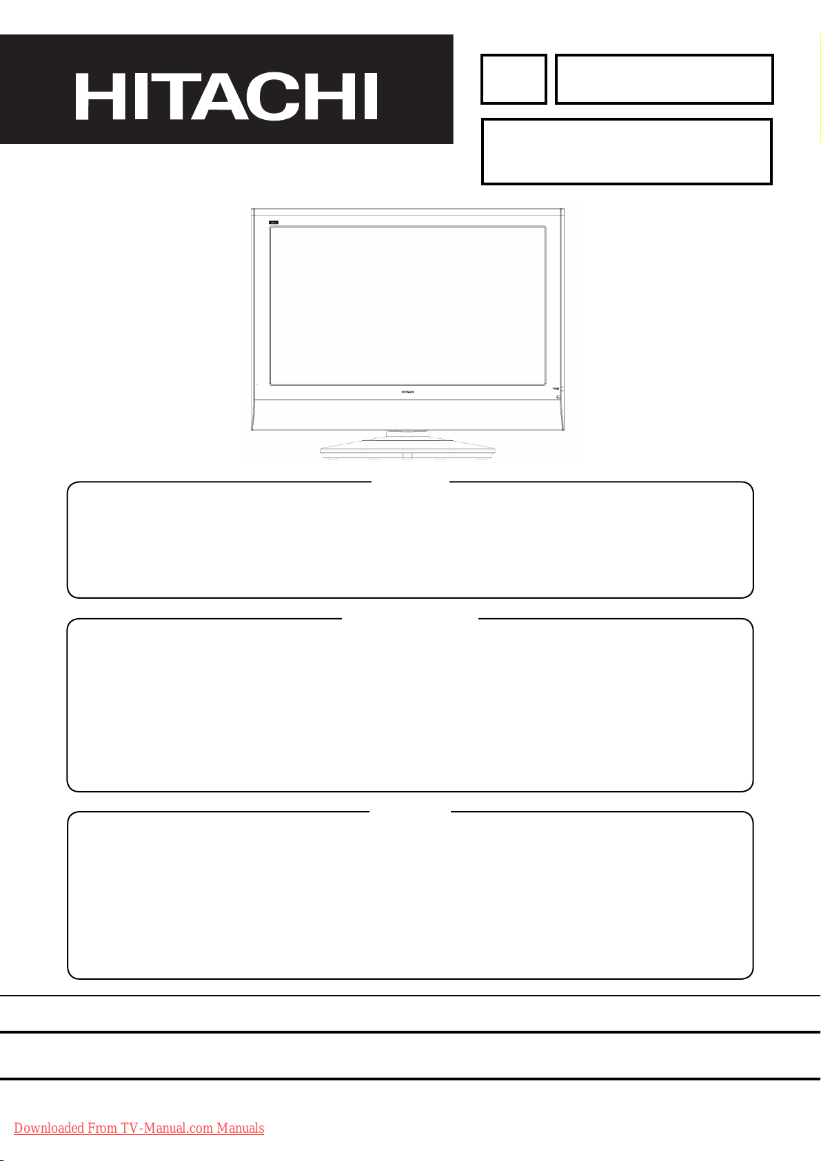
26LD8000TA
SERVICE MANUAL
Caution
Be sure to read this manual before servicing. To ensure safety from fi re, electric shock, injury, harmful radiation
and materials, various measures are provided in this LCD TV. Be sure to read cautionary items described in
the manual before servicing. These servicing instructions are for use by qualifi ed service personnel only. To
reduce the risk of electric shock, do not perform any servicing other than that described in the operating
instructions unless you are qualifi ed to do so.
Service Warning
1. Replacement work should be started after the Panel Module and the AC/DC Power supply have become
suffi ciently cool.
2. Special care should be taken when working near the display area in order not to damage its surface.
3. The Panel Module should not be touched with bare hands in order to protect its surface from blemishes
and damage.
4. It is recommended that you use clean soft gloves during the replacement work in order to protect not only
the display area of the Panel Module but also yourself.
Contents
1. Features --------------------------------------------------3
2. Specifi cations --------------------------------------------4
3. Component names -------------------------------------5
4. Service point ---------------------------------------------7
5. Adjustment -----------------------------------------------8
6. Troubleshooting --------------------------------------- 16
7. Self-diagnosis function ------------------------------ 21
SPECIFICATIONS AND PARTS ARE SUBJECT TO CHANGE FOR IMPROVEMENT.
8. Block diagram ----------------------------------------- 23
9. Wiring diagram ---------------------------------------- 25
10. Circuit diagram ---------------------------------------- 26
11. Printed wiring board diagram ---------------------- 42
12. Disassembly diagram -------------------------------- 46
13. Replacement parts list ------------------------------- 48
Downloaded From TV-Manual.com Manuals
LCD Television
July 2005 Digital Media Division
Page 2
CAUTION FOR SAFETY
Please read this page before repair the TV.
The following safety precautions are designed to help you stay safe and prevent accidents during the repair
work.
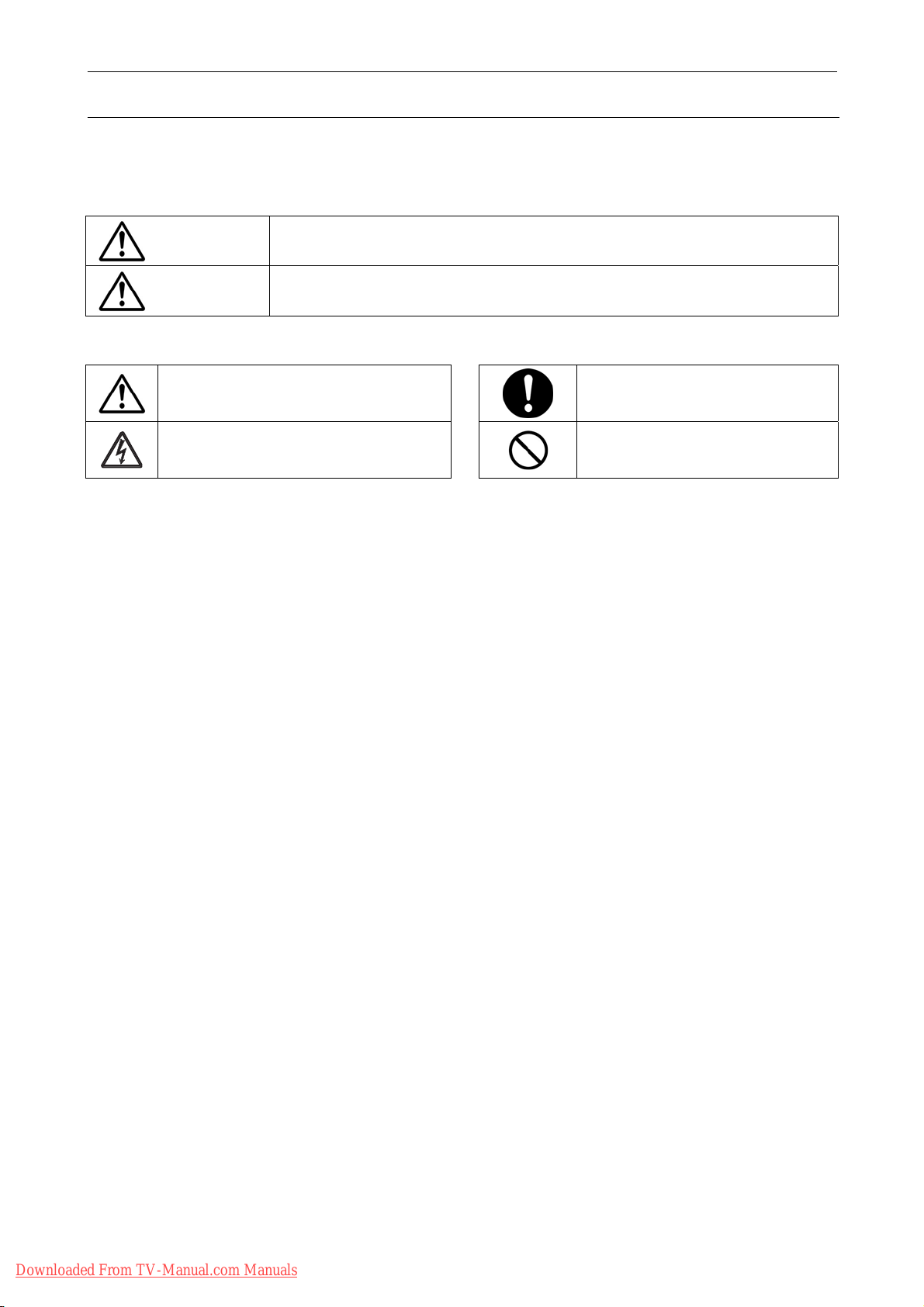
z Please take note of these cautionary flags.
Warning
Caution
z Also note these cautionary icons
This means "CAUTION"
This means "Potential to sustain injury or even death."
This means "Potential to sustain breakage or irreparable damage."
This means "POTENTIAL ELECTRIC
SHOCK"
This means "MUST"
This means "DO NOT"
Downloaded From TV-Manual.com Manuals
2
Page 3
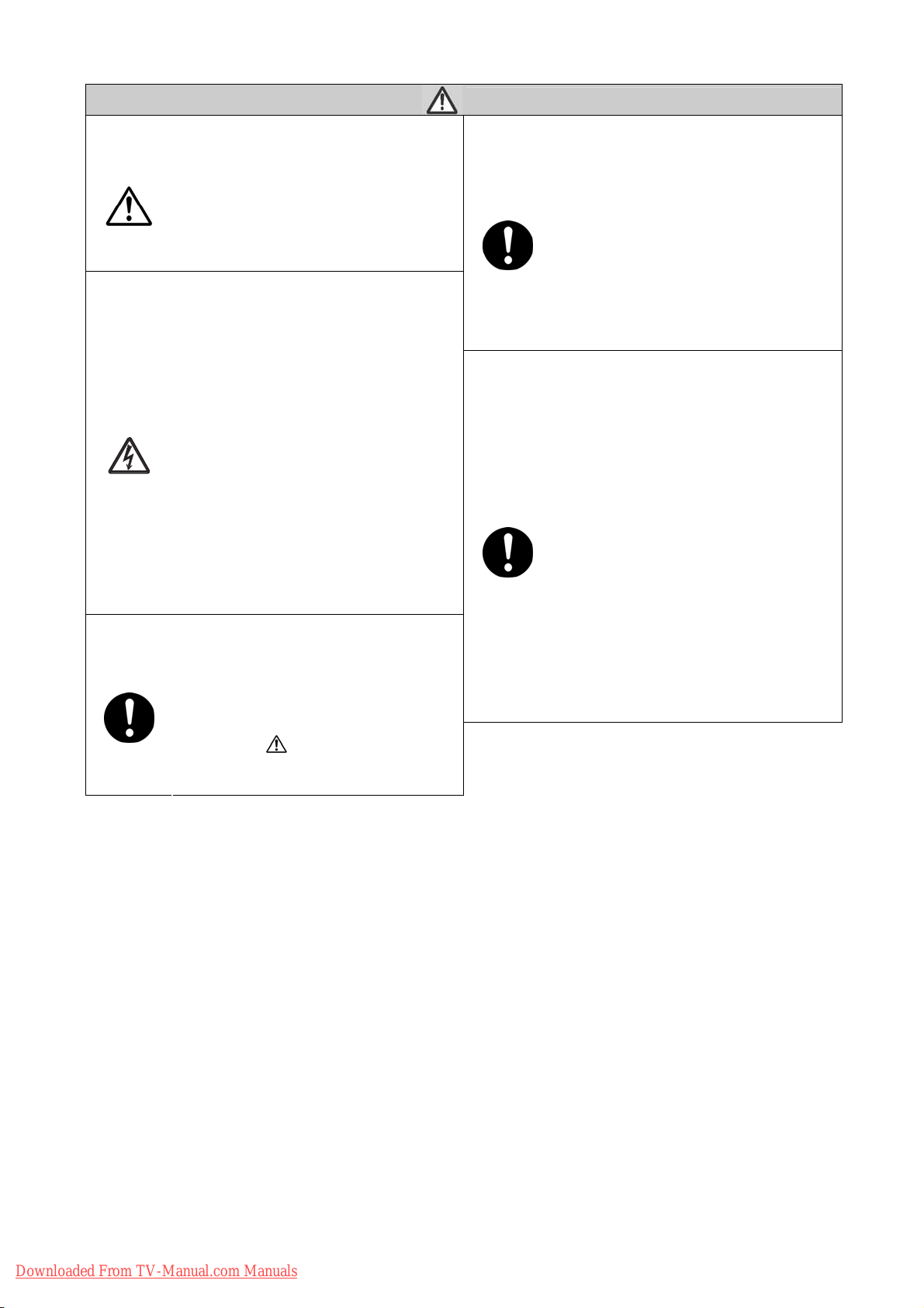
WARNING
Follow instructions. Must use same types of wires and components.
The cabinet, chassis, and labels are parts
that require attention. You must follow the
caution notes and safety instructions
presented throughout this User Manual to
prevent damage to them or injury to
yourself.
Prevent electric shock.
Exercise caution while working on the
device as the TV contains high voltage
parts and
supply.It is possible to sustain severe
injury or death if you accidentally touch
the wrong parts.You must disconnect the
power supply while servicing,
reassembling, or change parts. If you
touch a live connection it is possible to
sustain severe injury or death.
Use recommended components.
Use only the recommended components
or componentst that structurally identical
to the originals. This is to ensure safety
and reliability. Pay special attention to
parts in the parts list and circuit diagrams
marked with
non-recommended components, then
electric shock or fire may result.
. If you use
Perform safety check when done.
The TV uses special tubes and tapes
made from insulated materials. Moreover,
some materials are kept from making
contact with the PWB for the sake of
safety.Internal leads are kept from hot
parts or high voltage parts by means of
clamps or other measures. As such, you
must restored these parts to their original
conditions in order to prevent electric
shock or fire.
Every part (such as removed screws,
components, and wiring) must be
restored to their prior conditions after
servicing.Be sure to check everything that
was repaired for damage or mistakes.
Also measure the insulated impedance
with a meg-ohm meter to confirm that the
impedance value is more than 4M ohm.If
the impedance value is less than 4M
ohm, then electric shock or fire may
result.
3
Downloaded From TV-Manual.com Manuals
Page 4

PRECAUTIONS
z Cleaning the TV’s LCD screen panel
Before cleaning the TV, turn it off and disconnect the power plug from the power outlet. To prevent scratching
or damaging of the LCD screen face, do not knock or rub the surface with sharp or hard objects. Clean the
screen with a soft cloth moistened with warm water and dry with a second soft cloth. If it is not enough, then
use a cloth with mild detergent. Do not use harsh or abrasive cleaners.
z Cleaning the TV's cabinet
Use a soft cloth to clean the TV's cabinet and control panel. When excessively soiled, dilute a neutral
detergent in water, wet and wring out the soft cloth in it, gently clean the cabinet, and then wipe it down with a
dry soft cloth.
Never use acid/alkaline detergents, alcoholic detergents, abrasive cleaners, powder soaps, OA cleaners, car
wax, glass cleaners, and so on. They will cause discoloration, scratches or cracks.
1. Features
z Enhanced definition LCD display panel
The 26-inch color LCD display panel, with a resolution of 1366 (H) x 768(V) pixels, creates a widescreen
picture. This panel features a thin form factor and can be hung on a wall with an optional wall mounting kit.
z High Performance Digital Processor
This panel displays a wide range of personal computer signals from 640 x 480, 800 x 600 SVGA to 1280 x
768 WXGA.(RGB Analog input).
z Easy-to-use remote control and on-screen display system
The included remote control operates all TV functions. Futhermore, the on-screen display system shows
the status of the control settings in an easy-to-view fashion.
z Power saving system
When connected to a VESA DPMS-compliant PC, the TV cuts its power consumption while idle.
Downloaded From TV-Manual.com Manuals
4
Page 5
2. Specifications
Display
Panel
Net dimensions 661.9 (W) x 522.5 (H) x 266.9(D) mm (With Base)
Net weight 18 kg (With Base)
Ambient
conditions
Power supply AC100 - 240V, 50/60Hz
Power consumption/at standby <120W / <1W
Audio output Build in 10W + 10W (4 Ω)
(RGB input)
dimensions
Resolution 1366 (H) x 768 (V) pixels
Temperatur Operating: 0°C to 40°C, Storage: -15°C to 50°C
Relative umidity Operating: 20% to 80%, Storage: 20% to 90% (non-condensing)
Approx. 26.005nches (604 (H) x 323 (V) mm, diagonal 600.53mm)
Input terminals
Input signals
Recommended signal 5 modes
(Video input)
Input signals
Video output Signal
Recommended signal 5 modes
(TV RF input)
Video signals 0.7 V
Sync signals
Input terminals
Video signals
RGB1-VGA audio input terminal (3.5mm Stereo Mini Jack)
RGB1-VGA analog RGB input terminal (D-sub 15-pin)
H/V separate, TTL level [2kΩ ]
H/V composite, TTL level [2kΩ ]
Sync on green, 0.3 Vp-p [75Ω]
AV1 : Component input (Y-PbPr/Y-CbCr) (RCA)
AV1 : L/R audio input terminal(RCA)AV1 : L/R audio input terminal(RCA)
AV2 : Component input (Y-PbPr/Y-CbCr) (RCA)
AV2 : L/R audio input terminal(RCA)AV1 : L/R audio input terminal(RCA)
AV3 : Composite video input terminal(RCA)
AV3 : S video input teminal
AV3 : L/R audio input terminal(RCA)
AV4 : Composite video input terminal(RCA)
AV4 : S video input teminal
AV4 : L/R audio input terminal(RCA)
AV1 : NTSC-M / PAL
AV2 : NTSC-M / PAL
AV3 : NTSC-M / PAL / SECAM
AV4 : NTSC-M / PAL / SECAM
OUTPUT(TV): composite video TV-output terminal (RCA)
OUTPUT(TV): L/R audio TV- output terminal (RCA)
Input signals Input terminals Analog RF input terminal (NTSC/PAL/SECAM)
z It takes at least 30 minutes to attain the maximum picture quality.
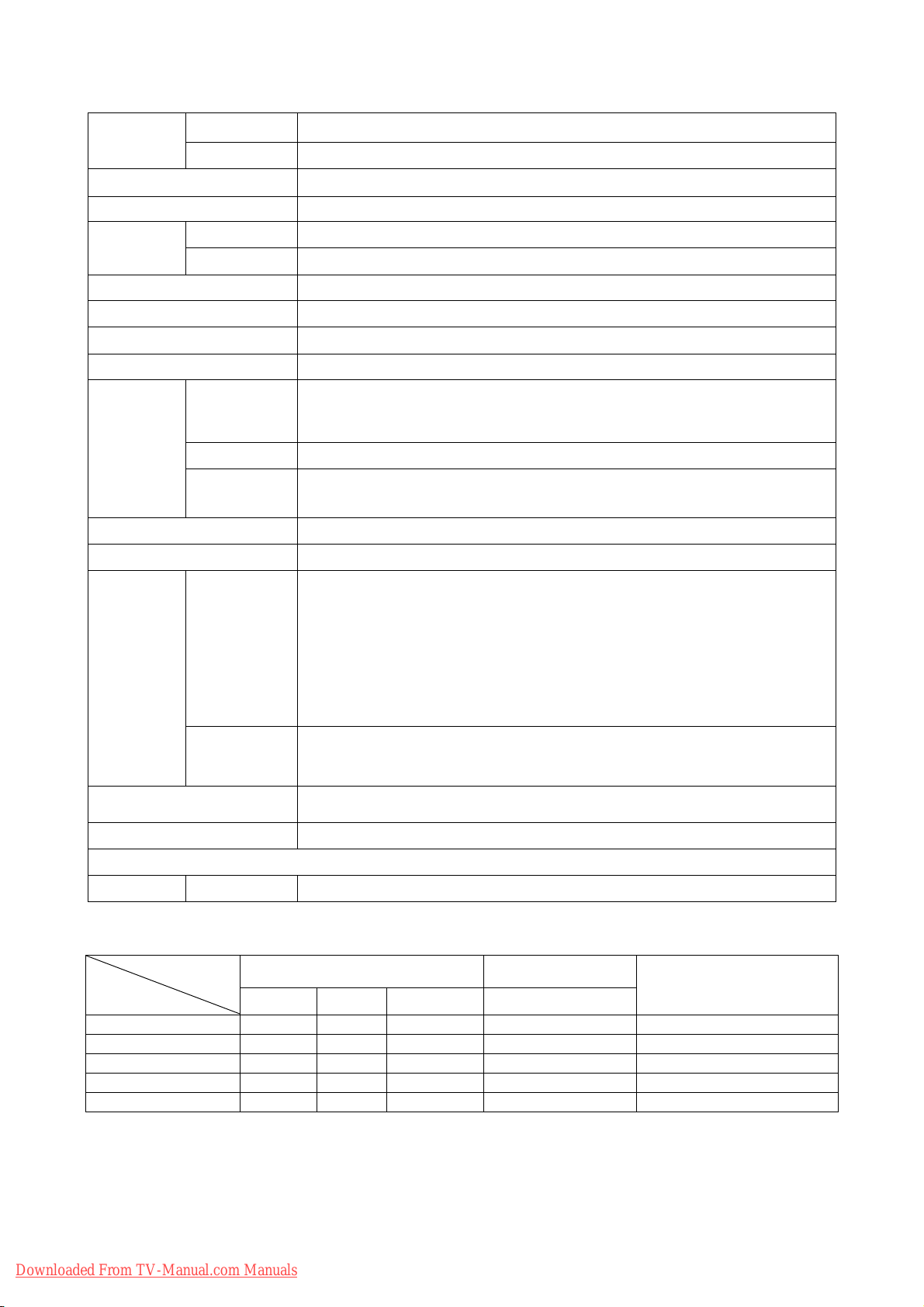
Applicable video signals for each input terminal
Signal Type
Terminal
AV1 { 480i/480p/1080i/720p inputs (PAL).
AV2 { 480i/480p/1080i/720p inputs (PAL).
AV3
AV4
RGB
Composite
Downloaded From TV-Manual.com Manuals
RCA D-sub
Remarks
S-video component
{ {
{ {
RGB
{
({: Avaliable)
5
Page 6
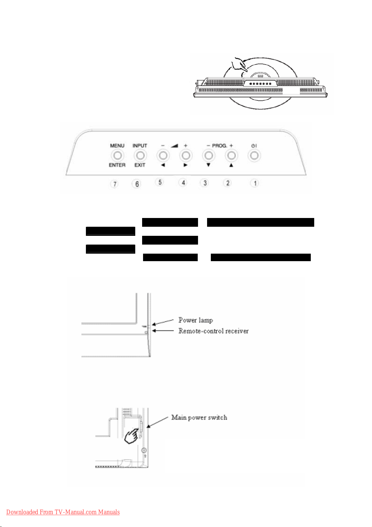
3..Component names
¾ [Main unit]
Control panel
z An Adjustment buttons are located on the top of
the control panel
z Indications for each button's function can be found
on the inside of the control panel cover.
1. SUB-POWER 4. VOL X 7.MENU
2. PROGRAM S
2. UP S 5. VOL W
3. PROGRAM T
3. DOWN T 6. INPUT Normal Button Action
4. RIGHTX 7.ENTER
5. LEFT W
6.EXIT Button Action when MENU engaged
Downloaded From TV-Manual.com Manuals
The main power switch is located at the right
side of the back.
6
Page 7
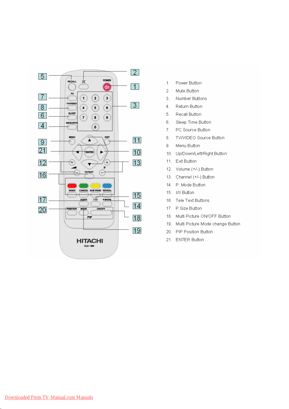
¾ [Remote Control]
Downloaded From TV-Manual.com Manuals
7
Page 8
4.Service points
z Lead-free solder
This product uses lead-free solder (unleaded) to help protect the environment. Please read these instructions
before attempting any soldering work.
Caution: Always wear safety glasses to prevent fumes or molten solder from getting into
the eyes. Lead-free solder can splatter at high temperatures (600℃).
Lead-free solder indicator
Printed circuit boards using lead-free solder are engraved with an
label.
Properties of lead-free solder
The melting point of lead-free solder is 40-50℃ higher than leaded solder.
Servicing solder
Solder with an alloy composition of Sn-3.0Ag-0.5Cu or Sn-0.7Cu is recommended. Although servicing with
leaded solder is possible, there are a few precautions that have to be taken. (Not taking these precautions
may cause the solder to not harden properly, and lead to consequent malfunctions.)
Precautions when using leaded solder
z Remove all lead-free solder from soldered joints when replacing components.
z If leaded solder should be added to existing lead free joints, mix in the leaded solder thoroughly after the
lead-free solder has been completely melted (do not apply the soldering iron without solder).
Servicing soldering iron
A soldering iron with a temperature setting capability (temperature control function) is recommended.
The melting point of lead-free solder is higher than leaded solder. Use a soldering iron that maintains a high
stable temperature (large heat capacity), and that allows temperature adjustment according to the part being
serviced, to avoid poor servicing performance.
Recommended soldering iron:
z Soldering iron with temperature control function (temperature range: 320-450℃)
Recommended temperature range per part:
Part Soldering iron temperature
Mounting (chips) on mounted PCB
Mounting (chips) on empty PCB
Chassis, metallic shield, etc.
(1) IR PWB, KEY PWB, SW PWB,2* I/O PWB
(2) MAIN PWB
(3) POWER BOARD
Downloaded From TV-Manual.com Manuals
The PWB assembly which has used lead free solder
320℃±30℃
380℃±30℃
420℃±30℃
8
Page 9
5.Adjustment
5.1 SERVICE (FACTORY) MODE ACCESS
This model has a Factory Mode, where the technician can access and adjust some of the color temperature
settings. The Factory Mode has several different appearances, depending on the input signal.
Picture Setting
for Factory Model
Table1 TV
Table2 AV (composite)/SV(S-Video)
Table3 SV(S-video)
Table4 480i(component)
Table5 480p(component)
Table6 1080i/60(component)
Table7 720P/60(component)
Picture Setting
for Factory Model
NTSC
PAL
Table1 TV
Table2 AV (composite)/SV(S-Video)
Table3 SV(S-video)
Table4 576i(component)
Table5 576p(component)
Table6 1080i/50(component)
Table7 720P/50(component)
Preliminary
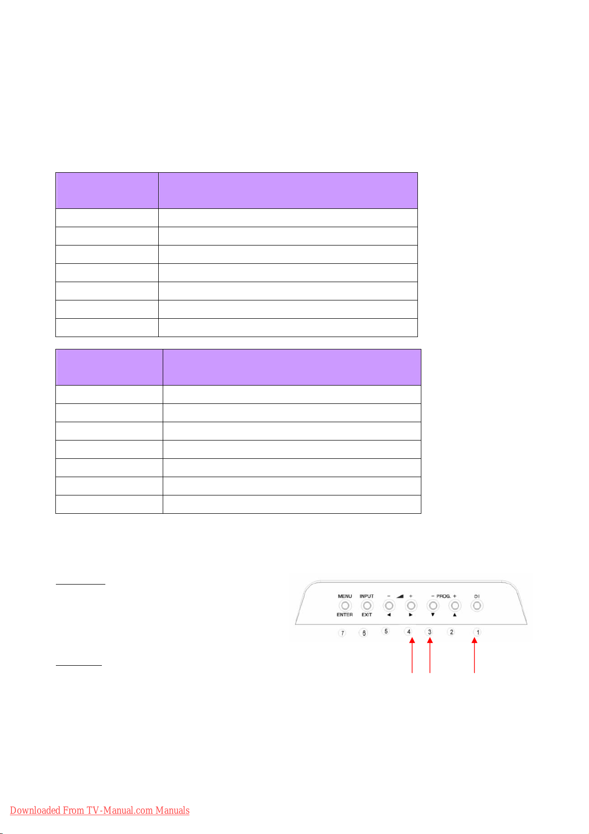
1. To access the Factory Mode, the TV must be
running.
Procedure
2. Press and hold the #3 and #4 button (PROGRAM
3. While continuing to hold the #3 and #4 button, press and hold the #1 button (SUB-POWER).
4. After both buttons have been held down for five (5) seconds, first release the #1 button, then release the
#3 and #4 button.
5. As stated previously, the input that the TV had selected at the time will determine which actual FACTORY
MODE display will show up. (See next page)
T and VOLUMES). ① ②
Downloaded From TV-Manual.com Manuals
9
Page 10
ENTER
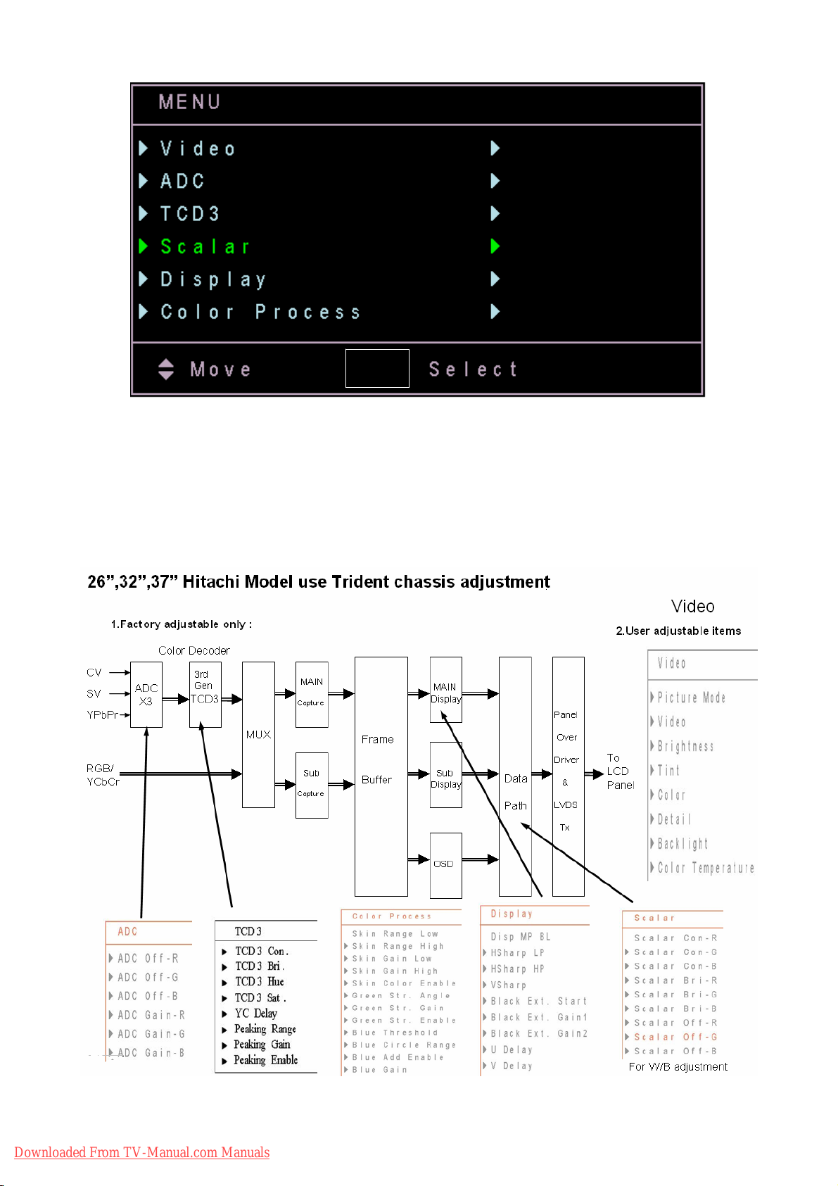
z FACTORY MODE NAVIGATION
To navigate through the different menu items, use the
S or T button on the remote control. The menu items
will be high-lighted green as navigation occurs. To access a particular adjustment parameter, use the
“ENTER” button on the remote control, which will cause a new menu to appear. To back up from the
FACTORY MODE, use the RETURN or EXIT button on the remote control. To leave the FACTORY MODE,
press POWER button on the remote control.
Downloaded From TV-Manual.com Manuals
10
Page 11
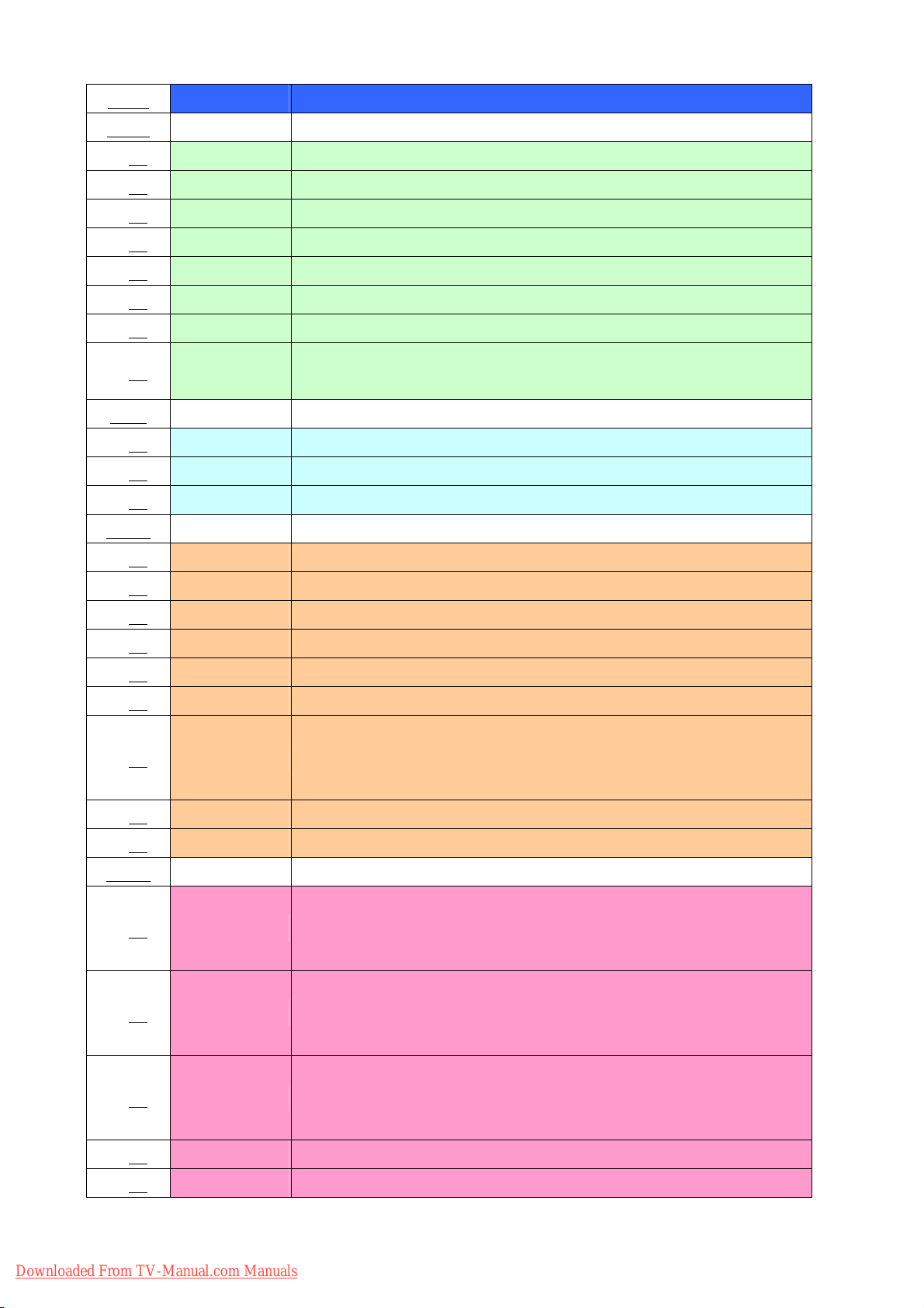
Menu Function Description
Video
Picture Mode OSD menu video mode default setting
Picture Display Contrast adjustment ( Back- end )
Brightness Display Brightness adjustment ( Back- end )
Tint Display Hue adjustment ( Back- end )
Color Display Saturation adjustment ( Back- end )
Detail Display Sharpness adjustment ( Back- end )
Backlight LCD backlight control ( Back- end )
Color temperature default setting ( High or Low )
Temperature
ADC
ADC Gain - R ADC input signal gain adjustment ( R/Pr ) , For D1 ~ D4 and PC only
ADC Gain - G ADC input signal gain adjustment ( G/Y ) , For D1 ~ D4 and PC only
ADC Gain - B ADC input signal gain adjustment ( B/Pb) , For D1 ~ D4 and PC only
TCD3
TCD3 Con. Video decoder contrast adjustment ( Front- end )
TCD3 Bri. Video decoder brightness adjustment ( Front- end )
TCD3 Hue Video decoder Hue adjustment ( Front- end )
TCD3 Sat. Video decoder Cr Saturation adjustment ( Front- end )
TCD3 Sat. Video decoder Cb Saturation adjustment ( Front- end )
YC Delay Video decoder YC delay adjustment ( Front- end )
Video decoder sharpness peaking range ( Front- end )
Color
Peaking Range
Ypeak = Y + YH * (peak_gain/peak_range) where Y is the luma and YH
is the high frequency luma only
Peaking Gain Video decoder sharpness peaking gain ( Front- end )
Peaking Enable Video decoder sharpness peaking function enable ( Front- end )
Scalar
Output R contrast factor adustment ( color temperature function )
Scalar Con - R
Output R = (( 'Output R + (Scalar Off-R)) * (Scalar Con-R) + (Scalar
Bri-R)
Output G contrast factor adustment ( color temperature function )
Scalar Con - G
Output G = (( 'Output G + (Scalar Off-G)) * (Scalar Con-G) + (Scalar
Bri-G)
Output B contrast factor adjustment ( color temperature function )
Scalar Con - B
Output B = (( 'Output B + (Scalar Off-B)) * (Scalar Con-B) + (Scalar
Bri-B)
Scalar Bri - R Output R brightness factor adustment ( color temperature function )
Scalar Bri - G Output G brightness factor adustment ( color temperature function )
11
Downloaded From TV-Manual.com Manuals
Page 12
Scalar Bri - B Output B brightness factor adustment ( color temperature function )
Scalar Off - R Output R offset factor adustment ( color temperature function )
Scalar Off - G Output G offset factor adustment ( color temperature function )
Scalar Off - B Output B offset factor adustment ( color temperature function )
Display
Disp MP BL
Display sharpness band pass gain of peaking adjustment ( Back- end ) ,
OSD sharpness adjustment item
HSharp LP Display sharpness low pass gain of peaking adjustment ( Back- end )
Display sharpness high pass gain of peaking adjustment ( Back- end ) ,
Hsharp HP
OSD sharpness adjustment item
Vsharp Display Vertical sharpness adjustment ( Back- end )
Black stretch start-point control factor. Higher value means more black
Black Ext. Start
stretch
( Back- end )
Black Ext.
Black stretch gain1
Gain1
Black Ext.
Black stretch gain2
Gain2
U Delay Display U delay ( comparing with Y )
V Delay Display Y delay ( comparing with V )
Color
Process
Skin color adjustment active range low
Low
Skin Range
Skin Range
Skin color adjustment active range high
High
Skin Gain Low Skin color adjustment gain of range low
Skin Gain High Skin color adjustment gain of range high
Skin Color
Skin color adjustment function enable
Enable
Green Str.
Green stretch active range ( UV domain green color active angle )
Angle
Green Str. Gain Green stretch gain
Green Str.
Green stretch function enable
Enable
Blue Threshold Blue add function active threshold
Blue Circle
Blue add function active range
Range
Blue Add Blue add function enable
Downloaded From TV-Manual.com Manuals
12
Page 13
Enable
Blue Gain Blue add gain
z COLOR TEMPERATURE ADJUSTMENTS
Following the procedures to make the color temperature adjustments. Note that a colorimetry meter (such as
a Minolta CA-210) is require
Low : x=0.301 +/- 0.01, y=0.314 +/- 0.01 = Color Temp.: 7500K
High : x=0.266 +/- 0.01, y=0.264 +/- 0.01 = Color Temp.: 15000K
5.2 Firmware update
This model has a Debbug Mode, where the technician can debbug and update the firmware.
Preliminary
1.To access the Bebbug Mode, the TV must be
running.
Procedure
2. Press and hold the #2 and #5 button (PROGRAM S and VOLUME
3. After both buttons have been held down for five (5) seconds, then release the #2 and #5 button.
4. Click IAPWriter.EXE
d to measure the actual screen color temperature.
T).
5. Following window will be shown after IAPWriter.EXE is executed.
Downloaded From TV-Manual.com Manuals
13
Page 14
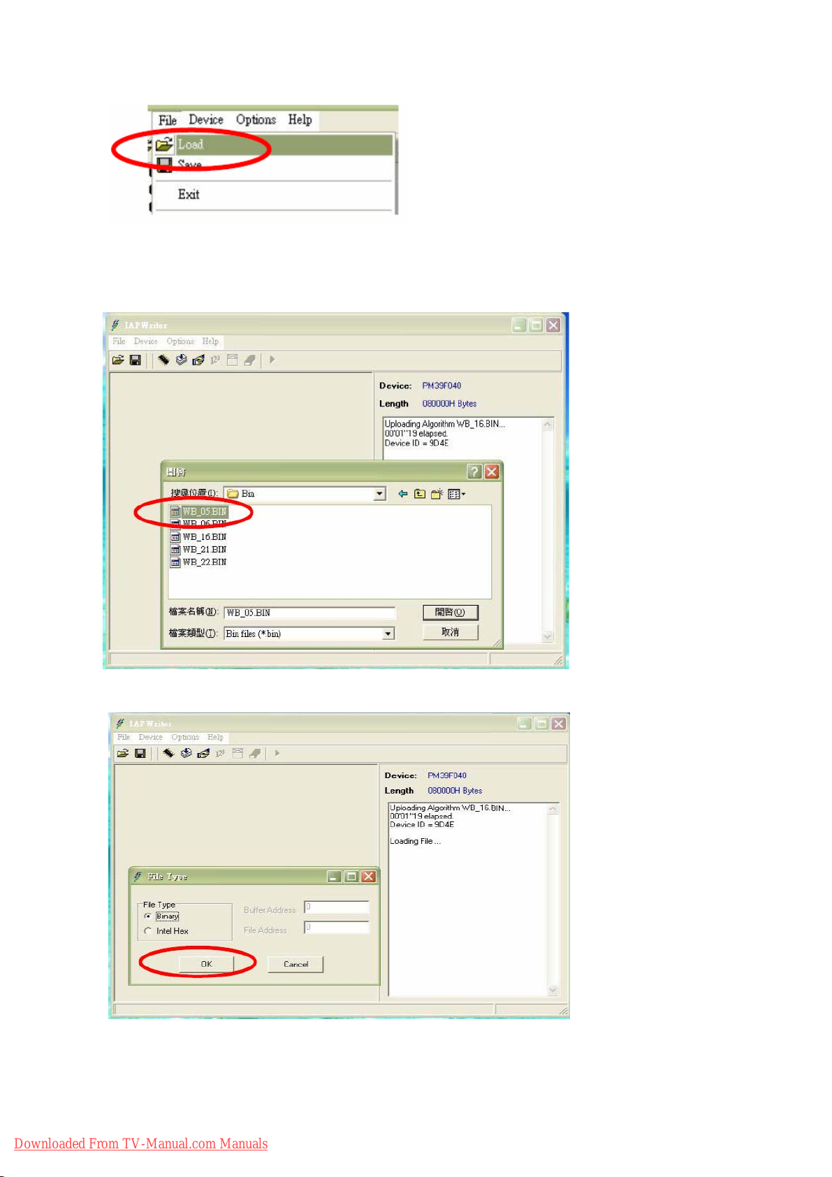
6. Load BIN file.
7. Click OK button
14
Downloaded From TV-Manual.com Manuals
Page 15
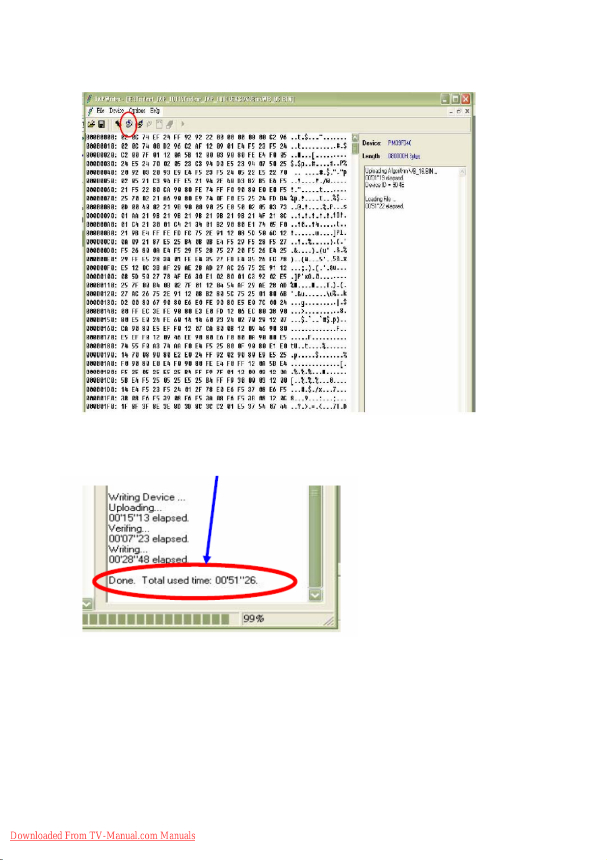
8. Click Write Device icon
9. IAP is finished while following massage is shown.
10. After IAP is done, please disconnect and reconnect AC power switch and do initialization.
Downloaded From TV-Manual.com Manuals
15
Page 16
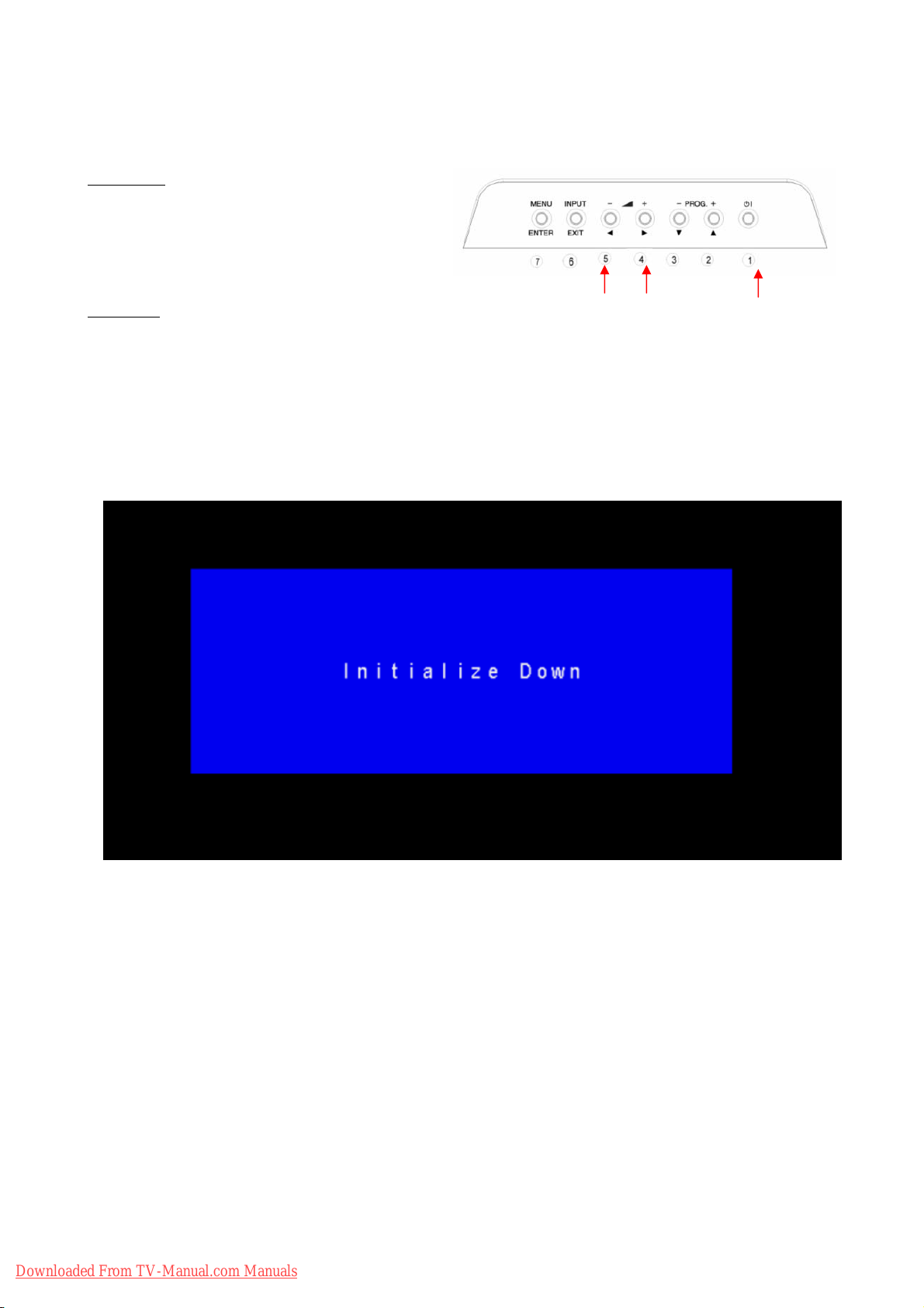
5.3 Initialization
This model has a Initialization Mode, where the technician can initial the EEPROM.
Preliminary
1.To access the Bebbug Mode, the TV must be
running.
Procedure
6. Press and hold the #4 and #5 button (VOLUMES and VOLUME
① ②
T).
7. While continuing to hold the #4 and #5 button, press and hold the #1 button (SUB-POWER).
8. After both buttons have been held down for five (5) seconds, first release the #1 button, then release the
#4 and #5 button.
9. As stated previously, the input that the TV had selected at the time will determine which actual
INITIALIZATION display will show up. (See below)
Downloaded From TV-Manual.com Manuals
16
Page 17

6.Troubleshooting
The flow chart shown below will help you to troubleshoot your TV set with it doesn’t display normally. Each
procedure offers a simple way to check for system errors. Before starting, ensure that there is a signal in and
that the TV is turned on.
Downloaded From TV-Manual.com Manuals
17
Page 18

Downloaded From TV-Manual.com Manuals
18
Page 19

Downloaded From TV-Manual.com Manuals
19
Page 20

Downloaded From TV-Manual.com Manuals
20
Page 21

Downloaded From TV-Manual.com Manuals
21
Page 22

7.Self Diagnosis Function
If a problem arises while you are using the TV, please read this self diagram function guide carefully before you ask to
have the TV repaired. You may be able to fix it easily by yourself. For example, if the mains plug is disconnected from the
mains outlet, or the TV aerial has problems, you may think there is a problem with the TV itself.
Important:
z This self diagram function guide only covers problems whose causes are not easy to decide. If you have a question
when you are operating a function, read the page(s) for that function carefully, not this self diagram function guide.
z If you follow the advice in this self diagram function guide without any success, unplug the mains plug and ask your
TV to be repaired. Do not attempt tp repair the TV by yourself or to remove the rear cover of the TV.
If you cannot turn on the TV:
z Are the AC plug on the power cordfrom the TV is connected to AC outlet?
Poor picture:
z If noise totally blocks out the picture , there may be a problem with the aerial or the aerial cable. Check the following
to try to solve the problem:
- Have the TV and aerial been connected properly?
- Has the aerial cable been damaged?
- Is the aerial pointing in the right direction?
- Is the aerial itself faulty?
z If the TV or aerial suffers interface from other equipment, stripes or noise may appear in the picture. Move any
equipment such as an amplifier, personal computer, or a hair drier, that can cause interference away from your TV.
Or try moving the TV. If the aerial suffers interference from a ratio tower or high-voltage wire, please contact your
local dealer.
z If the TV suffers interference from signals reflecting from mountains or buildings, double-pictures(ghosting) will
occur. Try to change the aerial’s direction or replace it with one with better directionality.
z Have the COLOR and BRIGHT settings been adjusted properly?
z Videotaping teletext is not recommended because it may not record correctly.
z When viewing images from commercially available video software products, or videos from videotapes which have
been recorded improperly, the top of the image may be distorted. This is due to the condition of the video signal.
There is nothing wrong with the TV.
Poor sound:
z Have you adjusted BASS or TREBLE properly?
If the TV does not respond to the remote control:
z Have the batteries of the remote control worn out?
z Have you attempted to use the remote control from the sides or rear of the TVor from more than seven metersaway
from the TV? Use the remote control in the front of your TV or from less than seven meters away.
z If the TV suddenly stops responding, disconnect the power cord of the TV from the AC outlet. Connect them to the
AC outlet again to turn on the TV. If the TV returns to a normal state, it is not a failure.
Downloaded From TV-Manual.com Manuals
22
Page 23

Other concerns:
z When the SLEEP TIMER function operates, the TV is auto matically turned off. If the TV suddenly turns off, try to
press the standby button to turn on the TV once again. If the TV goes back to normal, there is no problem.
z It takes a short period of time from the time an operation such as changing channels is performed until an image is
displayed. This is not a malfunction. This is the time required for the image to stabilize it can be displayed.
z The TV may make a crackling sound due to a sudden change in temperature. The picture or sound may be normal.
If you hear crackling sounds frequently while you are viewing the TV, there may be other causes. As a precaution,
ask your service technician to inspect it.
z The top of the TV and the screen may become hot during use but this has no effect on the performance of the TV.
Ensure that the ventilation holes are not blocked.
z When the picture is unstable, the screen may become white for a moment. This occurs when the signal which drives
the liquid crystal is missing. This is not a malfunction.
z When a still image has been displayed for a long period, a faint residual image may remain on the screen for a short
time after the power has been turned off or when another image is displayed. This is not a malfunction and the
image will eventually disappear.
Downloaded From TV-Manual.com Manuals
23
Page 24

8.Block Diagram
¾ LCD-TV
Downloaded From TV-Manual.com Manuals
24
Page 25

Downloaded From TV-Manual.com Manuals
25
Page 26

9. Wiring Block Diagram
Downloaded From TV-Manual.com Manuals
26
Page 27

10. Circuit Diagram
¾ Main Board (PWB-0885)
Downloaded From TV-Manual.com Manuals
27
Page 28

Downloaded From TV-Manual.com Manuals
28
Page 29

Downloaded From TV-Manual.com Manuals
29
Page 30

Downloaded From TV-Manual.com Manuals
30
Page 31

Downloaded From TV-Manual.com Manuals
31
Page 32

Downloaded From TV-Manual.com Manuals
32
Page 33

Downloaded From TV-Manual.com Manuals
33
Page 34

Downloaded From TV-Manual.com Manuals
34
Page 35

Downloaded From TV-Manual.com Manuals
35
Page 36

Downloaded From TV-Manual.com Manuals
36
Page 37

Downloaded From TV-Manual.com Manuals
37
Page 38

Downloaded From TV-Manual.com Manuals
38
Page 39

Downloaded From TV-Manual.com Manuals
39
Page 40

¾ I/O Board1 (PWB-0886)
Downloaded From TV-Manual.com Manuals
40
Page 41

¾ I/O Board2 (PWB-0887)
Downloaded From TV-Manual.com Manuals
41
Page 42

¾ Power Board
Downloaded From TV-Manual.com Manuals
42
Page 43

11. Printed Wiring Board Diagram
¾ Main Board-Top side(PWB-0885)
Downloaded From TV-Manual.com Manuals
43
Page 44

¾ I/O Board1-Top Side(PWB-0886)
¾ I/O Board2-Top Side (PWB-0887)
¾
Downloaded From TV-Manual.com Manuals
44
Page 45

¾ Power Board
Downloaded From TV-Manual.com Manuals
45
Page 46

Downloaded From TV-Manual.com Manuals
46
Page 47

12. Disassembly Diagram
¾ Mechanical
Downloaded From TV-Manual.com Manuals
47
Page 48

Downloaded From TV-Manual.com Manuals
48
Page 49

z Mechanical & Packing Parts List(26LD8000TA)
NO. DESCRIPTION PART NO. HITACHI PART NO Q’TY.
M1 FRONT COVER ASSEMBLY 5095670823 1
a FRONT COVER(ASIA) E641104703 1
b LENS LED E640333200 1
c IR LENS E640333300 1
d SPONGE-H E642026412 4
e SPONGE-V E642026413 4
f IPS LABEL E642442200 1
M2 SIDE INPUT PANEL ASSEMBLY 5095670826 1
SIDE INPUT PANEL E642681500 1
SIDE TERMINAL PLATE E642441800 1
M3 TUNER PANEL E642323900 1
M4 TERMINAL PANEL ASSEMBLY 5095670827 1
TERMINAL PANEL E642324200 1
TERMINAL PLATE E642441700 1
M5 BACK COVER ASSEMBLY 5095670824 1
a BACK COVER E641104810 1
b POWER BUTTON ASM E642852501 1
c TUNER PLATE E642441900 1
49
Downloaded From TV-Manual.com Manuals
Page 50

d MODEL LABEL(TTL)(A05) E030538202 1
f
MODEL LABEL (TCN) (A05)
E030538204 1
M6 CONTROL BUTTON ASSEMBLY 5095670825 1
a CONTROL PANEL UP(ASIA) E642323202 1
b CONTROL BUTTON E642852301 1
M7 STAND ASSEMBLY 5095854669 1
a STAND TURN COVER(ASIA) E641418202 1
b STAND COVER(ASIA) E641418302 1
c STAND BASE E641418400 1
d STAND RING E641419600 1
e STAND BRACKET E640409900 1
f FOOT PAD E642030200 6
g STAND HINGE E648746800 1
h STAND BASE METAL E640409800 1
i STAND BASE LOOP E648743200 3
M8 STAND HINGE COVER(ASIA) E641418502 1
M9 PRWP-M3X14 5640228400 8
M10 CABLE CLAMP E642682000 1
M11 TAPE OF AL FOIL - - - - - - - - -
a TAPE OF AL FOIL E648006506 3
50
Downloaded From TV-Manual.com Manuals
Page 51

b TAPE OF AL FOIL E648006507 2
c TAPE OF AL FOIL E648006520 1
M12 RS CARTON I513580256 1
M13 EPS Bottom(BR) 1
I523580256
M14 EPS Bottom(BL)
1
M15 EPE Bag I533319256 1
M16 EPS Top(TR) 1
I523580156
M17 EPS Top(TL)
1
M18 Clip PE Bag I533251157 1
51
Downloaded From TV-Manual.com Manuals
Page 52

z Electrical Parts List (26LD8000TA)
NO. DESCRIPTION PART NO. HITACHI PART NO QT'Y
PB01 POWER MODULE + CASE FSP
P807
V901
ASSEMBLY PCB-MAIN BOARD (PWB-0885-A)
ASSEMBLY PCB-SIDE I/O (PWB-0886) 5097650503
ASSEMBLY PCB-REAR I/O (PWB-0887)
ASSEMBLY PCB-LED/IR(PWB-0885-B)
ASSEMBLY PCB-KEY PAD (PWB-0885-C)
ASSEMBLY PCB-AC SWITCH (PWB-0885-D)
POWER CORE (UK) (A05)
26"TFT Panel Module LPL (LC260WX2-SL01 )
6693006617 1
5098801042 1
5097650602 1
5098801043 1
5098801046 1
5098801045 1
E056706081 1
E051253001 1
SW01B QUICK TIE,PVC E071000001
P008A
P010A
P011A
P015A
V901A
V091B
Wire Ass'y W12/12P
Wire Ass'y W5/5P
Wire Ass'y W8/8P
Wire Ass'y W6/6P
Wire Ass'y W30/30P
Wire Ass'y W12/14/12P
E057412007 1
E057405010 1
E057408004 1
E057406003 1
E057430010 1
E057414004 1
1
1
P905A
SW01A
SP01
SP02
SP01A
RCU01
Y001
Wire Ass'y W4/2P
Wire Ass'y Inlet W3P
SPEAKER
SPEAKER
Wire Ass'y W2P Conn.
REMOTE CONTROLLER
USER’S MANUAL
E057404012 1
E057403012 1
E055100001 1
E055100001 1
E057402010 1
E052731083 1
E030037002 1
Downloaded From TV-Manual.com Manuals
52
Page 53

MEMO
Downloaded From TV-Manual.com Manuals
105
Page 54

26LD8000TA
TP01511
Downloaded From TV-Manual.com Manuals
YK No.019E Digital Media Division
 Loading...