

Page 1
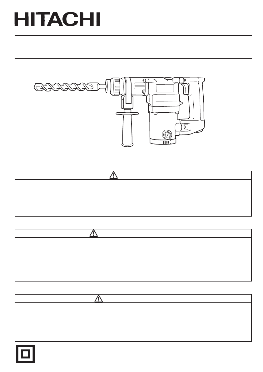
Model Rotary Hammer
Modèle Marteau rotatif
Modelo Martillo giratorio
DH 25PB
SAFETY INSTRUCTIONS AND INSTRUCTION MANUAL
WARNING
IMPROPER OR UNSAFE use of this power tool can result in death or serious bodily
injury!
This manual contains important information about product safety. Please read and
understand this manual BEFORE operating the power tool. Please keep this manual
available for other users and owners before they use the power tool. This manual should
be stored in safe place.
INSTRUCTIONS DE SECURITE ET MODE D’EMPLOI
AVERTISSEMENT
Une utilisation INCORRECTE OU DANGEREUSE de cet outil motorisé peut entraîner la
mort ou de sérieuses blessures corporelles!
Ce mode d’emploi contient d’importantes informations à propos de la sécurité de ce
produit. Prière de lire et de comprendre ce mode d’emploi AVANT d’utiliser l’outil
motorisé. Garder ce mode d’emploi à la disponibilité des autres utilisateurs et propriétaires
avant qu’ils utilisent l’outil motorisé. Ce mode d’emploi doit être conservé dans un
endroit sûr.
INSTRUCCIONES DE SEGURIDAD Y MANUAL DE INSTRUCCIONES
ADVERTENCIA
¡La utilización INAPROPIADA O PELIGROSA de esta herramienta eléctrica puede
resultar en lesiones de gravedad o la muerte!
Este manual contiene información importante sobre la seguridad del producto. Lea y
comprenda este manual ANTES de utilizar la herramienta eléctrica. Guarde este manual
para que puedan leerlo otras personas antes de utilizar la herramienta eléctrica. Este
manual debe ser guardado en un lugar seguro.
DOUBLE INSULATION
DOUBLE ISOLATION
AISLAMIENTO DOBLE
Page 2

English
IMPORTANT SAFETY INFORMATION ................ 3
MEANINGS OF SIGNAL WORDS ........................ 3
SAFETY ...................................................................... 4
GENERAL SAFETY RULES ................................... 4
SPECIFIC SAFETY RULES AND SYMBOLS ......... 6
DOUBLE INSULATION FOR SAFER
OPERATION ................................................... 8
FUNCTIONAL DESCRIPTION .................................... 9
NAME OF PARTS .................................................. 9
SPECIFICATIONS .................................................. 9
CONTENTS
Page Page
ASSEMBLY AND OPERATION ............................... 10
APPLICATIONS ................................................... 10
PRIOR TO OPERATION ....................................... 10
HOW TO USE ...................................................... 12
HOW TO USE THE CORE BIT
(FOR LIGHT LOAD) ...................................... 15
MAINTENANCE AND INSPECTION ....................... 17
ACCESSORIES ......................................................... 19
STANDARD ACCESSORIES ............................... 19
OPTIONAL ACCESSORIES ................................. 19
Français
INFORMATIONS IMPORTANTES DE
SÉCURITÉ ..................................................... 25
SIGNIFICATION DES MOTS
D’AVERTISSEMENT .................................... 25
SECURITE ................................................................ 26
REGLES GENERALE DE SECURITE ................... 26
REGLES DE SECURITE SPECIFIQUES ET
SYMBOLES .................................................. 28
DOUBLE ISOLATION POUR UN
FONCTIONNEMENT PLUS SUR ................. 30
DESCRIPTION FONCTIONNELLE ........................... 31
NOM DES PARTIES ............................................ 31
SPECIFICATIONS ................................................ 31
TABLE DES MATIERES
Español
INFORMACIÓN IMPORTANTE SOBRE
SEGURIDAD ................................................. 47
SIGNIFICADO DE LAS PALABRAS DE
SEÑALIZACIÓN ............................................ 47
SEGURIDAD ............................................................. 48
NORMAS GENERALES DE SEGURIDAD ........... 48
NORMAS Y SÍMBOLOS ESPECÍFICOS DE
SEGURIDAD ................................................. 50
AISLAMIENTO DOBLE PARA OFRECER UNA
OPERACIÓN MÁS SEGURA ........................ 52
DESCRIPCIÓN FUNCIONAL .................................... 54
NOMENCLATURA ............................................... 54
ESPECIFICACIONES ............................................ 54
Page Page
ASSEMBLAGE ET FONCTIONNEMENT ................ 32
APPLICATIONS ................................................... 32
AVANT L’UTILISATION ...................................... 32
UTILISATION ....................................................... 34
COMMENT UTILISER LA COURONNE
(POUR UNE CHARGE LEGERE) .................. 37
ENTRETIEN ET INSPECTION .................................. 39
ACCESSOIRES ......................................................... 41
ACCESSOIRES STANDARD ............................... 41
ACCESSOIRES SUR OPTION ............................. 41
ÍNDICE
Page Page
MONTAJE Y OPERACIÓN ...................................... 55
APLICACIONES ................................................... 55
ANTES DE LA OPERACIÓN ................................ 55
COMO SE USA .................................................... 57
MODO DE USAR LA BARRENA TUBULAR
(PARA CARGAS LIGERAS) .......................... 60
MANTENIMIENTO E INSPECCIÓN ........................ 63
ACCESORIOS ........................................................... 65
ACCESORIOS ESTÁNDAR ................................. 65
ACCESORIOS OPCIONALES .............................. 65
2
Page 3

English
IMPORTANT SAFETY INFORMATION
Read and understand all of the safety precautions, warnings and operating instructions in
the Instruction Manual before operating or maintaining this power tool.
Most accidents that result from power tool operation and maintenance are caused by the
failure to observe basic safety rules or precautions. An accident can often be avoided by
recognizing a potentially hazardous situation before it occurs, and by observing appropriate
safety procedures.
Basic safety precautions are outlined in the “SAFETY” section of this Instruction Manual
and in the sections which contain the operation and maintenance instructions.
Hazards that must be avoided to prevent bodily injury or machine damage are identified by
WARNINGS on the power tool and in this Instruction Manual.
NEVER use this power tool in a manner that has not been specifically recommended by
HITACHI.
MEANINGS OF SIGNAL WORDS
WARNING indicates a potentially hazardous situations which, if ignored, could result in
death or serious injury.
CAUTION indicates a potentially hazardous situations which, if not avoided, may result in
minor or moderate injury, or may cause machine damage.
NOTE emphasizes essential information.
3
Page 4

English
SAFETY
GENERAL SAFETY RULES
WARNING: Read and understand all instructions.
Failure to follow all instructions listed below, may result in electric
shock, fire and/or serious personal injury.
SAVE THESE INSTRUCTIONS
1. Work Area
(1) Keep your work area clean and well lit. Cluttered benches and dark areas invite
accidents.
(2) Do not operate power tools in explosive atmospheres, such as in the presence of
flammable liquids, gases, or dust. Power tools create sparks which may ignite the
dust of fumes.
(3) Keep bystanders children, and visitors away while operating a power tool.
Distractions can cause you to lose control.
2. Electrical Safety
(1) Double Insulated tools are equipped with a polarized plug (one blade is wider than
the other.) This plug will fit in a polarized outlet only one way. If the plug does not
fit fully in the outlet, reverse the plug. If it still does not fit, contact a qualified
electrician to install a polarized outlet. Do not change the plug in any way. Double
Insulation
grounded power supply system.
(2) Avoid body contact with grounded surfaces such as pipes, radiators, ranges and
refrigerators. There is an increased risk of electric shock if your body is grounded.
(3) Do not expose power tools to rain or wet conditions. Water entering a power tool
will increase the risk of electric shock.
(4) Do not abuse the cord. Never use the cord to carry the tools or pull the plug from
a receptacle. Keep cord away from heat, oil, sharp edges or moving parts. Replace
damaged cords immediately. Damaged cords increase the risk of electric shock.
(5) When operating a power tool outside, use an outdoor extension cord marked “W-
A” or “W”. These cords are rated for outdoor use and reduce the risk of electric
shock.
3. Personal Safety
(1) Stay alert, watch what you are doing and use common sense when operating a
power tool. Do not use tool while tired or under the influence of drugs, alcohol, or
medication. A moment of inattention while operating power tools may result in
serious personal injury.
(2) Dress properly. Do not wear loose clothing or jewelry. Contain long hair. Keep
your hair, clothing and gloves away from moving parts. Loose clothes, jewelry, or
long hair can be caught in moving parts.
(3) Avoid accidental starting. Be sure switch is off before plugging in. Carrying tools
with your finger on the switch or plugging in tools that have the switch on invites
accidents.
4
eliminates the need for the three wire grounded power cord and
Page 5

English
(4) Remove adjusting keys or wrenches before turning the tool on. A wrench or a key
that is left attached to a rotating part of the tool may result in personal injury.
(5) Do not overreach. Keep proper footing and balance at all times. Proper footing and
balance enables better control of the tool in unexpected situations.
(6) Use safety equipment. Always wear eye protection. Dust mask, non-skid safety
shoes, hard hat, or hearing protection must be used for appropriate conditions.
4. Tool Use and Care
(1) Use clamps or other practical way to secure and support the workpiece to a stable
platform. Holding the work by hand or against your body is unstable and may lead
to loss of control.
(2) Do not force tool. Use the correct tool for your application. The correct tool will do
the job better and safer at the rate for which it is designed.
(3) Do not use tool if switch does not turn it on or off. Any tool that cannot be controlled
with the switch is dangerous and must be repaired.
(4) Disconnect the plug form the power source before making any adjustments,
changing accessories, or storing the tool. Such preventive safety measures reduce
the risk of starting the tool accidentally.
(5) Store idle tools out of reach of children and other untrained persons. Tools are
dangerous in the hands of untrained users.
(6) Maintain tools with care. Keep cutting tools sharp and clean. Properly maintained
tools, with sharp cutting edges are less likely to bind and are easier to control.
(7) Check for misalignment or binding of moving parts, breakage of parts, and any
other condition that may affect the tools operation. If damaged, have the tool
serviced before using. Many accidents are caused by poorly maintained tools.
(8) Use only accessories that are recommended by the manufacturer for your model.
Accessories that may be suitable for one tool, may become hazardous when used
with another tool.
5. Service
(1) Tool service must be performed only by a qualified repair personnel. Service or
maintenance performed by unqualified personnel could result in a risk of injury.
(2) When servicing a tool, use only identical replacement parts. Follow instructions in
the Maintenance section of this manual. Use of unauthorized parts or failure to
follow Maintenance Instruction may create a risk of electric shock or injury.
5
Page 6

English
SPECIFIC SAFETY RULES AND SYMBOLS
1. Hold tools by insulated gripping surfaces when performing an operation where the
cutting tool may contact hidden wiring or its own cord. Contact with a “live” wire will
make exposed metal parts of the tool “live” and shock the operator.
2. ALWAYS wear ear protectors when using the tool for extended periods.
Prolonged exposure to high intensity noise can cause hearing loss.
3. NEVER touch the tool bit with bare hands after operation.
4. NEVER wear gloves made of stuff liable to roll up such as cotton, wool, cloth or string,
etc.
5. ALWAYS attach the side handle and securely grip the Rotary Hammer.
6. NEVER touch moving parts.
NEVER place your hands, fingers or other body parts near the tool’s moving parts.
7. NEVER operate without all guards in place.
NEVER operate this tool without all guards or safety features in place and in proper
working order. If maintenance or servicing requires the removal of a guard or safety
feature, be sure to replace the guard or safety feature before resuming operation of the
tool.
8. Use right tool.
Don’t force small tool or attachment to do the job of a heavy-duty tool.
Don’t use tool for purpose not intended —for example— don’t use circular saw for
cutting tree limbs or logs.
9. NEVER use a power tool for applications other than those specified.
NEVER use a power tool for applications other than those specified in the Instruction
Manual.
10. Handle tool correctly.
Operate the tool according to the instructions provided herein. Do not drop or throw
the tool. NEVER allow the tool to be operated by children, individuals unfamiliar with
its operation or unauthorized personnel.
11. Keep all screws, bolts and covers tightly in place.
Keep all screws, bolts, and plates tightly mounted. Check their condition periodically.
12. Do not use power tools if the plastic housing or handle is cracked.
Cracks in the tool’s housing or handle can lead to electric shock. Such tools should not
be used until repaired.
13. Blades and accessories must be securely mounted to the tool.
Prevent potential injuries to youself or others. Blades, cutting implements and
accessories which have been mounted to the tool should be secure and tight.
14. Keep motor air vent clean.
The tool’s motor air vent must be kept clean so that air can freely flow at all times.
Check for dust build-up frequently.
6
Page 7
English
15. Operate power tools at the rated voltage.
Operate the power tool at voltages specified on its nameplate.
If using the power tool at a higher voltage than the rated voltage, it will result in
abnormally fast motor revolution and may damage the unit and the motor may burn
out.
16. NEVER use a tool which is defective or operating abnormally.
If the tool appears to be operating unusually, making strange noises, or otherwise
appears defective, stop using it immediately and arrange for repairs by a Hitachi
authorized service center.
17. NEVER leave tool running unattended. Turn power off.
Don’t leave tool until it comes to a complete stop.
18. Carefully handle power tools.
Should a power tool be dropped or struck against hard materials inadvertently, it may
be deformed, cracked, or damaged.
19. Do not wipe plastic parts with solvent.
Solvents such as gasoline, thinner benzine, carbon tetrachloride, and alcohol may
damage and crack plastic parts. Do not wipe them with such solvents.
Wipe plastic parts with a soft cloth lightly dampened with soapy water and dry
thoroughly.
20. ALWAYS wear eye protection that meets the requirement of the latest revision of ANSI
Standard Z87.1.
21. ALWAYS be careful with buried object such as an underground wiring.
Touching these active wiring or electric cable with this tool, you may receive an electric
shock.
Confirm if there are any buried object such as electric cable within the wall, floor or
ceiling where you are going to operate here after.
22. Definitions for symbols used on this tool
V ............volts
Hz .......... hertz
A ............ amperes
o ........... no load speed
n
W ........... watt
........... Class II Construction
---/min ... revolutions per minute
.......... Alternating current
7
Page 8

English
DOUBLE INSULATION FOR SAFER OPERATION
To ensure safer operation of this power tool, HITACHI has adopted a double insulation
design. “Double insulation “ means that two physically separated insulation systems have
been used to insulate the electrically conductive materials connected to the power supply
from the outer frame handled by the operator. Therefore, either the symbol “
words “Double insulation” appear on the power tool or on the nameplate.
Although this system has no external grounding, you must still follow the normal electrical
safety precautions given in this Instruction Manual, including not using the power tool in
wet environments.
To keep the double insulation system effective, follow these precautions:
䡬 Only HITACHI AUTHORIZED SERVICE CENTER should disassemble or assemble this
power tool, and only genuine HITACHI replacement parts should be installed.
䡬 Clean the exterior of the power tool only with a soft cloth moistened with soapy water,
and dry thoroughly.
Never use solvents, gasoline or thinners on plastic components; otherwise the plastic
may dissolve.
” or the
SAVE THESE INSTRUCTIONS
AND
MAKE THEM AVAILABLE TO
OTHER USERS
AND
OWNERS OF THIS TOOL!
8
Page 9
English
FUNCTIONAL DESCRIPTION
NOTE: The information contained in this Instruction Manual is designed to assist you in
the safe operation and maintenance of the power tool.
NEVER operate, or attempt any maintenance on the tool unless you have first read
and understood all safety instructions contained in this manual.
Some illustrations in this Instruction Manual may show details or attachments that
differ from those on your own power tool.
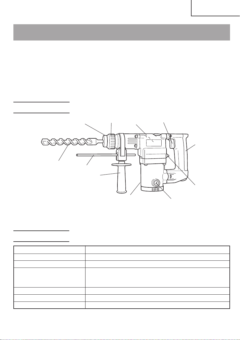
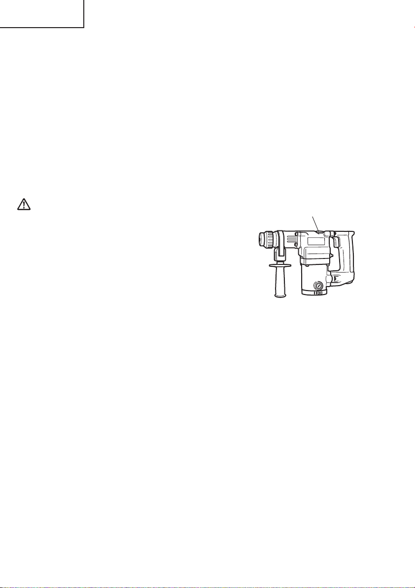
NAME OF PARTS
Drill bit
Front cap
Stopper
Side
handle
Grip
Nameplate
Housing
Fig. 1
Trigger
Handle
Change lever
Brush cap
SPECIFICATIONS
Motor Single-Phase, Series Commutator Motor
Power Source Single-Phase, 120V 60Hz
Current 5.7A
Capacity Concrete: 1/8" – 1" (3.4mm – 25mm)
Steel: 1/2"(13mm)
Wood: 1-1/4" (32mm)
No-Load Speed 0 – 1100/min.
Full-load Impact Rate 0 – 4000/min.
Weight 7.5 lbs (3.4 kg)
9
Page 10
English
ASSEMBLY AND OPERATION
APPLICATIONS
Rotation and striking function
䡬 Drilling anchor holes
䡬 Drilling holes in concrete
䡬 Drilling holes in tile
Rotation only function
䡬 Drilling in steel or wood (with optional accessories).
䡬 Tightening machine screws, wood screws (with optional accessories).
PRIOR TO OPERATION
1. Power source
Ensure that the power source to be utilized conforms to the power source requirements
specified on the product nameplate.
2. Power switch
Ensure that the switch is in the OFF position. If the plug is connected to a receptacle
while the switch is in the ON position, the power tool will start operating immediately
and can cause serious injury.
3. Extension cord
When the work area is far away from the power source, use an extension cord of
sufficient thickness and rated capacity. The extension cord should be kept as short as
practicable.
WARNING:
Damaged cord must be replaced or repaired.
4. Check the receptacle
If the receptacle only loosely accepts the plug, the receptacle must be repaired. Contact
a licensed electrician to make appropriate repairs.
If such a fautly receptacle is used, it may cause overheating, resulting in a serious
hazard.
5. Confirming condition of the environment:
Confirm that the work site is placed under appropriate conditions conforming to
prescribed precautions.
10
Page 11
English
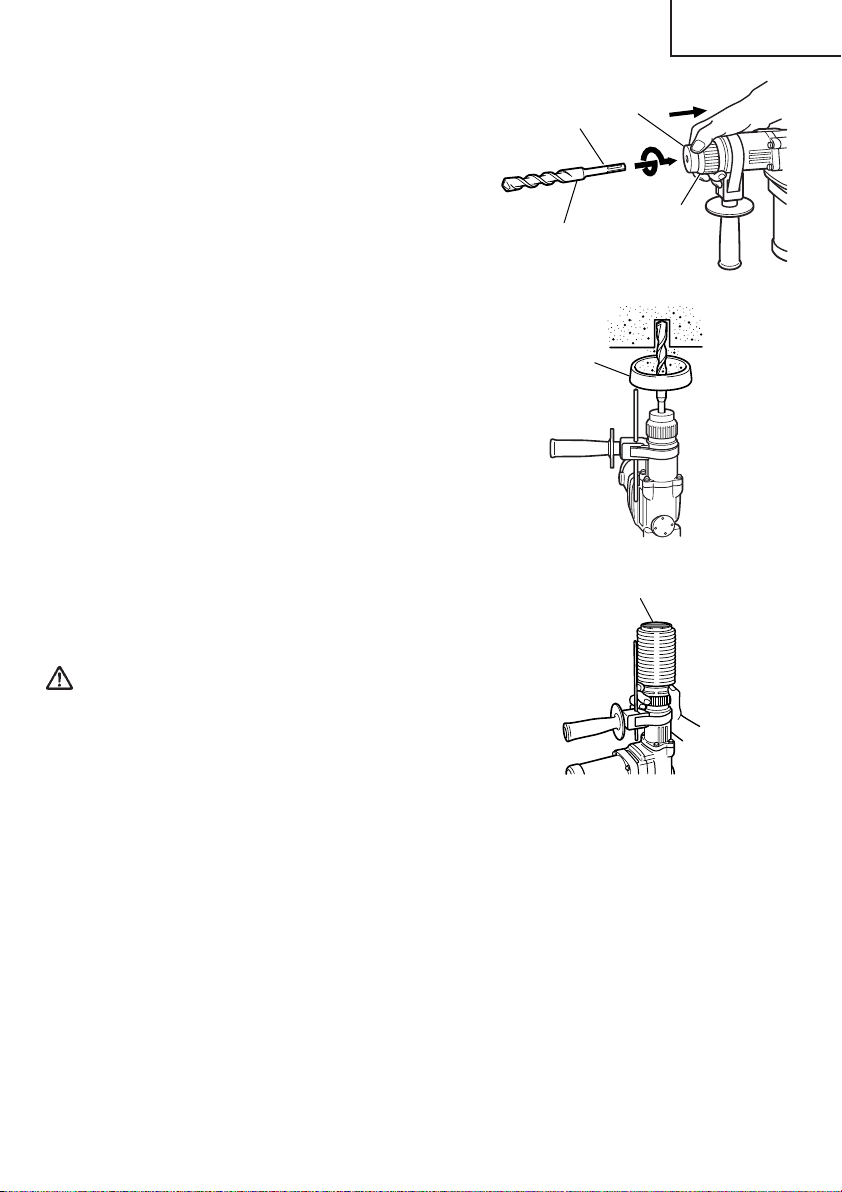
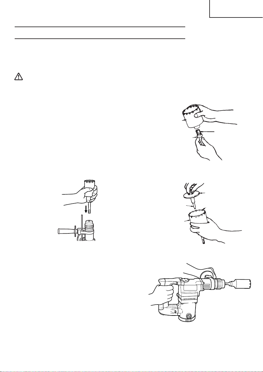
6. Mounting the drill bit (Fig. 2)
(1) To attach a drill bit (SDS-plus shank), fully pull
the grip in the direction of the arrow as shown
in Fig. 2 and insert the drill bit as far as it will
go while manually turning.
(2) By releasing the grip, the drill bit will be
secured.
(3) To remove the drill bit, fully pull the grip in
the direction of the arrow and pull out the drill
bit.
7. Installation of dust cup or dust collector
(B) (Optional accessories) (Fig. 3, Fig. 4)
When using a rotary hammer for upward
drilling operations attach a dust cup or dust
collector (B) to collect dust or particles for easy
operation.
䡬 Installing the dust cup
Use the dust cup by attaching to the drill bit a
shown in Fig. 3.
When using a bit which has big diameter,
enlarge the center hole of the dust cup with
this rotary hammer.
䡬 Installing dust collector (B)
When using dust collector (B), insert dust
collector (B) from the tip of the bit by aligning
it to the groove on the grip (Fig. 4)
Part of SDS-plus
Front cap
shank
Grip
Drill bit
Fig. 2
Dust cap
Fig. 3
Dust collector (B)
CAUTION:
䢇 The dust cup and dust collector (B) are for
exclusive use of concrete drilling work. Do not
use them for wood or metal drilling work.
䢇 Insert dust collector (B) completely into the
chuck part of the main unit.
䢇 When turning the rotary hammer on while dust collector (B) is detached from a concrete
surface, dust collector (B) will rotate together with the drill bit. Make sure to turn on
the switch after pressing dust cup on the concrete surface. (When using dust collector
(B) attached to a drill bit that has more than 7-15/32" (190 mm) of overall length, dust
collector (B) cannot touch the concrete surface but rotates. Therefore please use dust
collector (B) by attaching to drill bits which have 6-17/32" (166 mm), 6-19/64" (160
mm) and 4-21/64" (110 mm) overall length.
䢇 Dump particles after every two or three holes when drilling.
䢇 Please replace the drill bit after removing dust collector (B).
Fig. 4
8. Selecting the driver bit
Screw heads or bits will be damaged should an inappropriate bit for the screw diameter
be employed to drive in the screws.
11
Page 12
English
HOW TO USE
CAUTION:
䢇 To prevent accidents, make sure to turn the
switch off and disconnect the plug from the
receptacle when the drill pits and other
various parts are installed or removed. The
power switch should also be turned off during
a work break and after work.
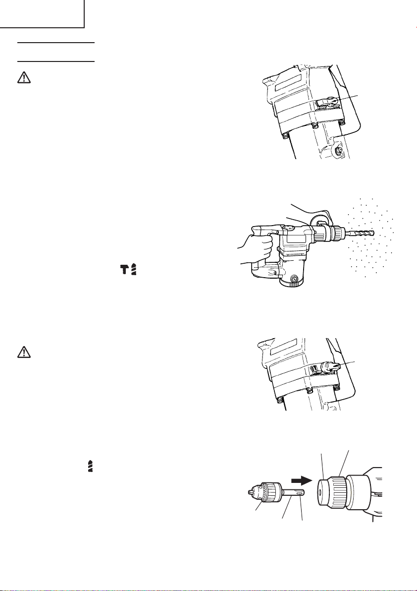
Change
lever
1. Switch operation
The rotation speed of the drill bit can be
controlled steplessly by varying the amount
that the trigger switch is pulled. Speed is low
when the trigger switch is pulled slightly and
increases as the switch is pulled more.
2. Rotation + Striking
This rotary hammer can be set to rotation and
striking mode by turning the change lever fully
counterclockwise to mark. (Fig. 5)
(1) Mount the drill bit.
(2) Pull the trigger switch after applying the drill
bit tip to the drilling position (Fig. 6)
(3) Pushing the rotary hammer forcibly is not
necessary at all. Pushing slightly so that drill
dust comes out gradually is just sufficient.
CAUTION:
䢇 When the drill bit touches an iron reinforcing
rod, the bit will stop immediately and the
rotary hammer will react to revolve. Therefore
please grip the side handle and handle tightly
as shown in Fig. 6.
3. Rotation only
This rotary hammer can be set to rotation only
mode by turning the change lever fully
clockwise to mark. (Fig. 7)
To drill a wood or metal material using the
separately sold drill chuck and chuck adaptor,
proceed as follows. Installing drill chuck and
chuck adaptor (Fig. 8):
(1) Mount the drill chuck to the chuck
adaptor.
(2) The part of the SDS-plus shank is the same as
the drill bit. Therefore, refer to the item of
“Mounting the drill bit” for attaching it.
12
Drill
chuck
Chuck
adaptor
Fig. 5
Fig. 6
Fig. 7
Front cap
Part of SDSplus shank
Fig. 8
Change
lever
Grip
Page 13
English
CAUTION:
䢇 Application of force more than necessary will not only reducing drilling efficiency at
all, but will deteriorate the tip edge of the drill bit and reduce the service life of the
rotary hammer in addition.
䢇 Drill bit may snap off while disengaging the rotary hammer from the jammed hole. For
disengaging, it is important to use a pushing motion or turn the drill bit
counterclockwise.
䢇 Do not attempt to drill anchor holes or holes in concrete with the main unit in the
rotation only function.
䢇 Do not attempt to use the rotary hammer in the rotation and striking function with
the drill chuck and chuck adaptor attached. This would seriously shorten the service
life of every components of the machine.
Bit
4. When driving machine screws (Fig. 9)
First, insert the bit into the socket in the end
of chuck adaptor (D).
Next, mount chuck adaptor (D) on the main
unit using procedures described in 6 (1), (2),
(3), put the tip of the bit in the slots in the head
of the screw, grasp the main unit and tighten
the screw.
CAUTION:
䢇 Exercise care not to excessively prolong
driving time, otherwise, the screws may be
damaged by excessive force.
䢇 Apply the rotary hammer perpendicularly to the screw head when driving a screw;
otherwise, the screw head or bit will be damaged, or driving force will not be fully
transferred to the screw.
䢇 Do not attempt to use the rotary hammer in the rotation and striking function with
chuck adaptor (D) and bit attached.
Socket
Chuck
adaptor (D)
Front cap
Grip
Fig. 9
5. When driving wood screws (Fig. 9)
(1) Selecting a suitable driver bit
Employ phillips screws, if possible, since the driver bit easily slips off the heads of
slotted-head screws.
(2) Driving in wood screws
䡬 Prior to driving in wood screws, make pilot holes suitable for them in the wooden
board. Apply the bit to the screw head grooves and gently drive the screws into the
holes.
䡬 After rotating the rotary hammer at low speed for a while until a wood screw in partly
driven into the wood, squeeze the trigger more strongly to obtain the optimum driving
force.
CAUTION:
䢇 Exercise care in preparing a pilot hole suitable for the wood screw taking the hardness
of the wood into consideration. Should the hole be excessively small or shallow,
13
Page 14
English
requiring much power to drive the screw into it, the thread of the wood screw may
sometimes be damaged.
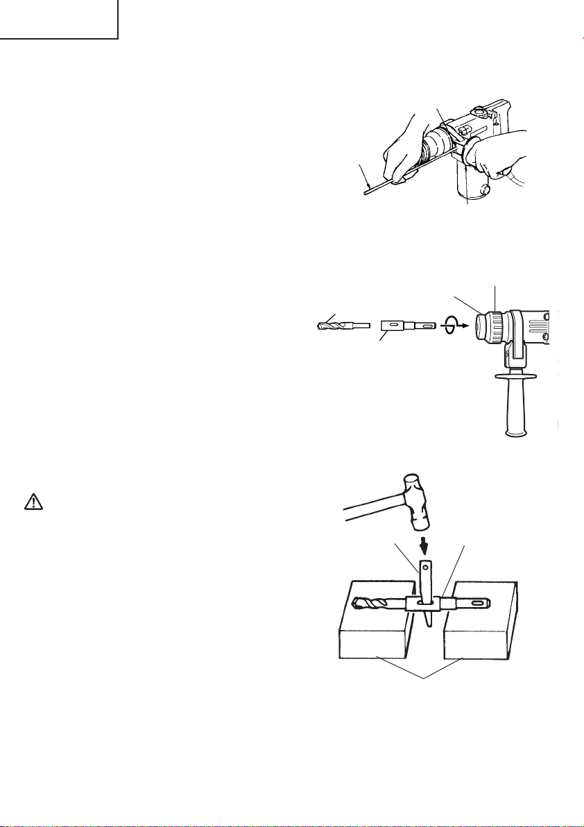
6. Using the stopper (Fig. 10)
(1) Loosen the knob on the side handle, and insert
the stopper into the mounting hole on the side
handle.
(2) Adjust the stopper position according to the
depth of the hole and tighten the knob
securely.
7. How to use the drill bit (taper shank) and
the taper shank adaptor.
(1) Mount the taper shank adaptor to the rotary
hammer. (Fig. 11)
(2) Mount the drill bit (taper shank) to the taper
shank adaptor. (Fig. 11)
(3) Turn the switch ON, and drill a hole in
prescribed depth.
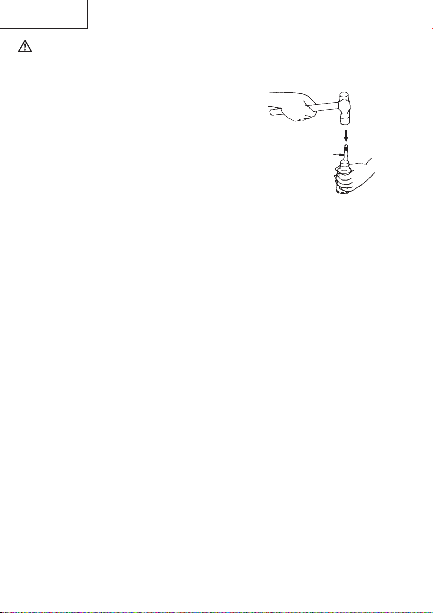
(4) To remove the drill bit (taper shank), insert
the cotter into the slot of the taper shank
adaptor and strike the head of the cotter with
a manual hammer supporting on the rests.
(Fig. 12)
Stopper
Drill bit
Taper shank
adaptor
Mounting
hole
Fig. 10
Front cap
Side handle
Grip
8. Using the side handle
When you wish to change a position of the
side handle, turn grip of the side handle
counterclockwise to loosen it, and then fasten
it firmly.
Fig. 11
CAUTION:
When boring a hole, there can be a case where
the machine attempts to rotate by the
reaction at the time of penetrating a concrete
wall and/or when a tip of the blade comes in
contact with the rebar.
Firmly fasten the side handle and hold the
machine with both of your hands. Unless you
hold it securely, an accident can occur.
14
Cotter
Taper shank adaptor
Rests
Fig. 12
Page 15
English
HOW TO USE THE CORE BIT (FOR LIGHT LOAD)
When boring penetrating large hole use the core bit (for light load). At that time use with
the center pin and the core bit shank provided as optional accessories.
1. Mounting
CAUTION:
䢇 Be sure to turn power OFF and disconnect the plug from the receptacle.
(1) Mount the core bit to the core bit shank.
(Fig. 13)
Lubricate the thread of the core bit shank to
facilitate disassembly.
(2) Mount the core bit shank to the rotary
hammer. (Fig. 14)
(3) Insert the center pin into the guide plate until
it stops.
(4) Engage the guide plate with the core bit, and
turn the guide plate to left or right so that it
does not fall even if it faced downward.
(Fig. 15)
Core bit
Thread
Core bit shank
Fig. 13
Guide plate
Center pin
Core bit
Fig. 14
Core bit tip
Fig. 15
2. How to bore (Fig. 16)
(1) Connect the plug to the power source.
(2) A spring is installed in the center pin. Push it
lightly to the wall or the floor perpendicularly.
Connect all over the surface of the core bit tip
and start operating.
(3) When boring about 3/16" (5 mm) in depth the
position of the hole will establish. Bore after
that removing the center pin and the guide
plate from core bit.
(4) Application of excessive force will not only expedite the work, but will deteriorate the
tip edge of the drill bit, resulting in reduced service life of the rotary hammer.
Fig. 16
15
Page 16
English
CAUTION:
䢇 When removing the center pin and the guide plate, turn OFF the switch and disconnect
the plug form the receptacle.
3. Dismounting. (Fig. 17)
Remove the core bit shank from the rotary
hammer and strike the head of the core bit
shank strongly two or three times with the
manual hammer holding the core bit, then the
thread becomes loose and the core bit can be
removed.
Core bit shank
Fig. 17
16
Page 17
English
MAINTENANCE AND INSPECTION
WARNING: Be sure to switch power OFF and disconnect the plug from the
receptacle during maintenance and inspection.
1. Inspecting the drill bits
Since use of a dull tool will cause motor malfunctioning and degraded efficiency, replace
the drill bit with a new one or resharpening without delay when abrasion is noted.
2. Inspecting the screws
Regularly inspect all screws and ensure that they are properly tightened. Should any of
the screws be loosened, retighten them immediately.
WARNING: Using this rotary hammer with loosened screws is extremely
dangerous.
3. Maintenance of the motor
The motor unit winding is the very “heart” of the power tool. Exercise due care to
ensure the winding does not become damaged and/or wet with oil or water.
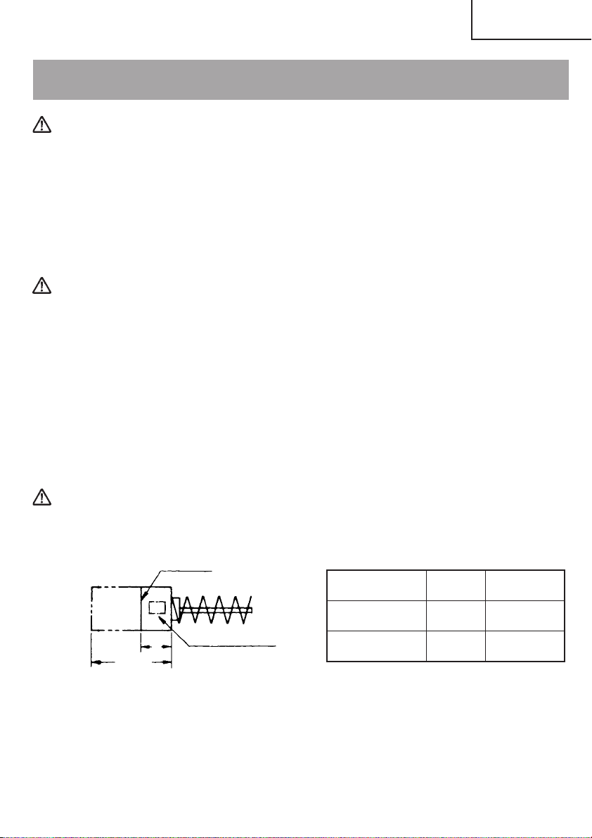
4. Inspecting the carbon brushes: (Fig. 18)
The motor employs carbon brushes which are consumable parts. When they become
worn to or near “wear limit”, it could result in motor trouble. When an auto-stop carbon
brush is equipped, the motor will stop automatically. At that time, replace both carbon
brushes with new ones which have the same carbon brush Nos. shown in the figure.
In addition, always keep carbon brushes clean and ensure that they slide freely within
the brush holders.
CAUTION:
Using this rotary hammer with a carbon brush which is worn in excess of the wear
limit will damage the motor.
Wear limit
a
carbon brush
Usual carbon 0.2"
brush (5 mm)
No. of carbon brush
a
0.47"
(12 mm)
Fig. 18
NOTE: Use HITACHI carbon brush No. indicated in Fig. 18.
Auto-stop
carbon brush
— 70
No. of
21
17
Page 18
English
䡬 Replacing carbon brushes:
(For parts name, refer to Fig. 1)
Loosen the two set screws and remove the tail cover. Remove the brush caps and
carbon brushes. After replacing the carbon brushes, tighten the brush caps securely
and to install the tail cover with securely tightening two set screws.
5. How to replase grease
This machine is full air-tight construction to protect against dust and to prevent lubricant
leakage. Therefore, the machine can be used without lubrication for long periods.
Replace the grease as described below.
䡬 Grease replacement period
You should look at the grease when you change the carbon brush. (See item 4 in the
section MAINTENANCE AND INSPECTION.) Ask for grease replacement at the nearest
HITACHI Authorized Service Center. Proceed for replacement of grease.
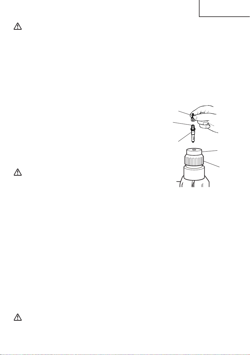
䡬 Grease replenishment
CAUTION:
Before replenishing the grease, turn the
power off and pull out the power plug.
(1) Disassemble the oil cap and thoroughly wipe
off the old grease inside. (FIg. 19)
(2) Supply 17.5g (the standard volume to cover
the connecting rod) of Hitachi Electric Hammer
Grease A in the crank case.
(3) After replacing the grease, reassemble the oil
cap securely. At this time, do not damage or
lose the O-Ring.
NOTE: The HITACHI Electric Hammer Grease A is of the lower viscosity type. When the
supplied grease tube is consumed, purchase from a HITACHI Autorized Service
Center.
Oil cap
Fig. 19
6. Service and repairs
All quality power tools will eventually require servicing or replacement of parts because
of wear from normal use. To assure that only authorized replacement parts will be
used, all service and repairs must be performed by a HITACHI AUTHORIZED SERVICE
CENTER, ONLY.
18
Page 19
English
ACCESSORIES
WARNING: ALWAYS use Only authorized HITACHI replacement parts and
accessories. NEVER use replacement parts or accessories which are
not intended for use with this tool. Contact HITACHI if you are not sure
whether it is safe to use a particular replacement part or accessory
with your tool.
The use of any other attachment or accessory can be dangerous and
could cause injury or mechanical damage.
NOTE: Accessories are subject to change without any obligation on the part of the HITACHI.
STANDARD ACCESSORIES
(1) Case (Molded plastic) (Code No. 318307).......................................................................1
(2) Side Handle (Code No. 980939).......................................................................................1
(3) Stopper (Code No. 980906)..............................................................................................1
(4) Dust Cup (Code No. 971787)............................................................................................1
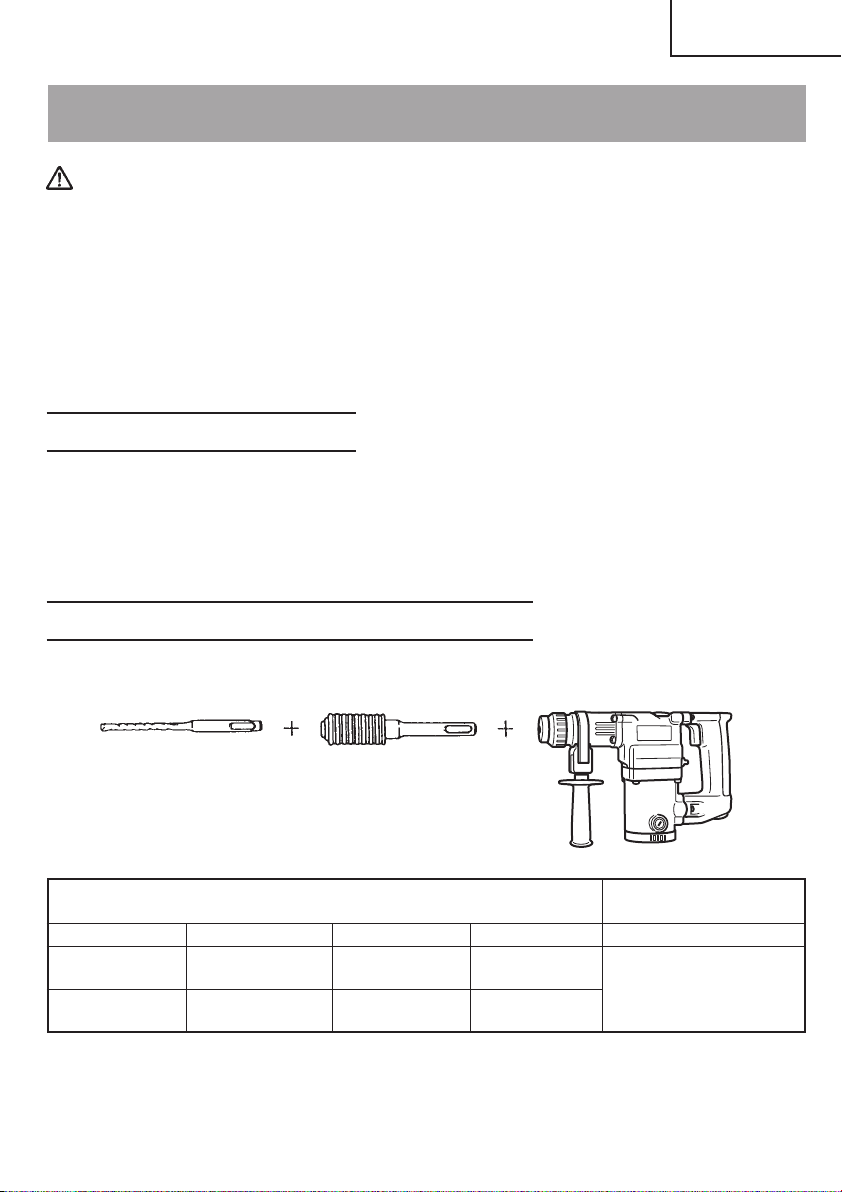
OPTIONAL ACCESSORIES........ sold separately
1. Drilling anchor holes (Rotation + Striking)
䡬 Drill Bit (Slender shaft)
(1) Drill Bit
(Slender Shaft)
(1) Drill Bit (Slender Shaft)
Outer diameter Effective Length Overall Length Code No. Code No.
1/8" 1-25/32" 3-35/64"
(3.4mm) (45mm) (90mm)
9/64" 1-25/32" 3-35/64"
(3.5mm) (45mm) (90mm)
(2) Adaptor for slender
shaft (SDS-plus
shank)
(2) Adaptor for
Slender Shaft
306369
306370
306368
19
Page 20
English
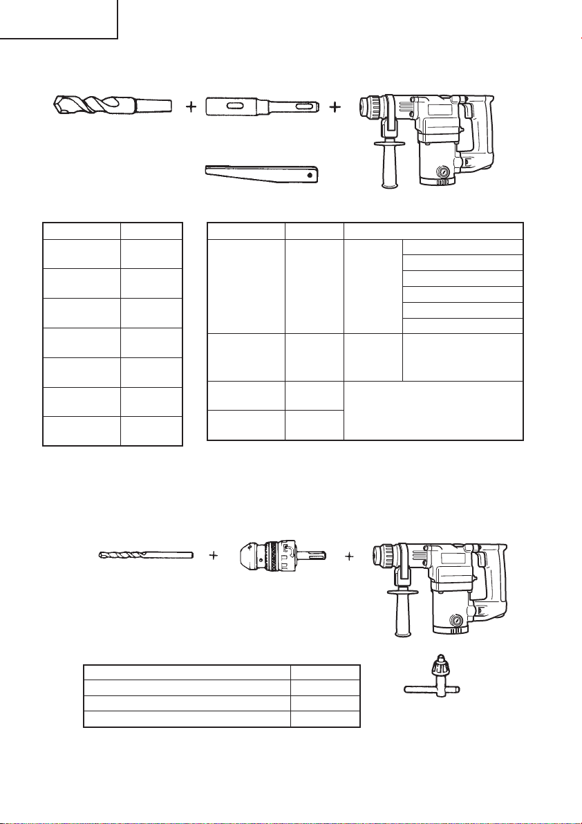
䡬 Drill Bit (Taper shank) and taper shank adaptor
(1) Drill Bit (Taper
Shank)
(2) Taper Shank Adaptor
(SDS-plus shank)
Cotter (Code No. 944477)
External dia. Code No.
7/16"
(11 mm)
31/64"
(12.3 mm)
1/2"
(12.7 mm)
9/16"
(14.3 mm)
73/128"
(14.5 mm)
11/16"
(17.5 mm)
27/32"
(21.5 mm)
944460
944461
993038
944462
944500
944463
944464
Taper mode Code No. Applicable drill bit
7/16" (11 mm)
31/64" (12.3 mm)
1/2" (12.7 mm)
9/16" (14.3 mm)
73/128" (14.5 mm)
11/16" (17.5 mm)
Morse taper
(No. 1)
Morse taper
(No. 2)
A-taper 303619
B-taper 303620
303617
303618 27/32" (21.5 mm)
Drill bit
(Taper
shank)
Drill bit
(Taper
shank)
Taper shank adaptor formed Ataper or B-taper is provided as
an optional accessory, but drill
bit for it is not provided.
䡬 1/2" (13 mm) Hammer Drill chuck and Chuck wrench
For drilling operations when using a straight shank bit for impact driling with a rotary
hammer
Impact Drill
Application
Straight shank Bit
Name Code No.
1/2" (13 mm) Hammer Drill Chuck 303332
Chuck wrench 303334
Rubber Cap 303335
20
1/2" (13 mm) Hammer Drill
Chuck (SDS-plus shank)
(includes Chuck wrench)
Chuck wrench
Page 21
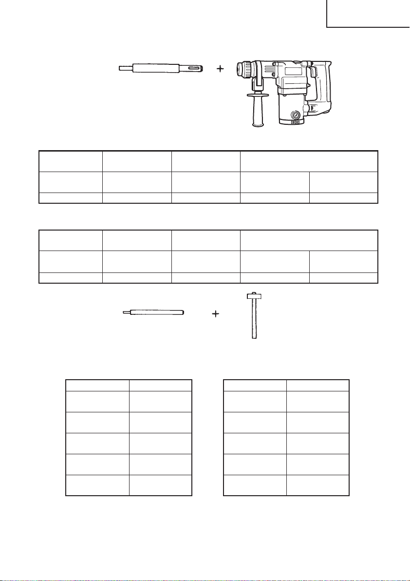
2. Knock-in anchor (Rotation + Striking)
Anchor Setter
(for anchor setting)
(SDS-plus shank)
<Outer wedge type with the female screw>
nchor size
A
Overall Length
Code No. 302976 302975 303621 302974
W 1/4" W 5/16" W 3/8"
(6.3 mm) (8 mm) (9.5 mm)
10-15/64" 10-15/64" 6-19/64" 10-15/64"
(260 mm) (260 mm) (160 mm) (260 mm)
<Inner wedge type with the headless screw>
nchor size
A
Overall Length
Code No. 302979 302978 303622 302977
W 1/4" W 5/16" W 3/8"
(6.3 mm) (8 mm) (9.5 mm)
10-15/64" 10-15/64" 6-19/64" 10-15/64"
(260 mm) (260 mm) (160 mm) (260 mm)
English
Anchor setting adaptor
(for manual hammer)
<Outer wedge type with
the female screw>
Anchor size Code No.
W1/4"
(6.3 mm)
W5/16"
(8 mm)
W3/8"
(9.5 mm)
W1/2"
(12.7 mm)
W5/8"
(15.9 mm)
971794
971795
971796
971797
971798
<Inner wedge type with
the headless screw>
Anchor size Code No.
W1/4"
(6.3 mm)
W5/16"
(8 mm)
W3/8"
(9.5 mm)
W1/2"
(12.7 mm)
W5/8"
(15.9 mm)
971799
971800
971801
971802
971803
21
Page 22
English
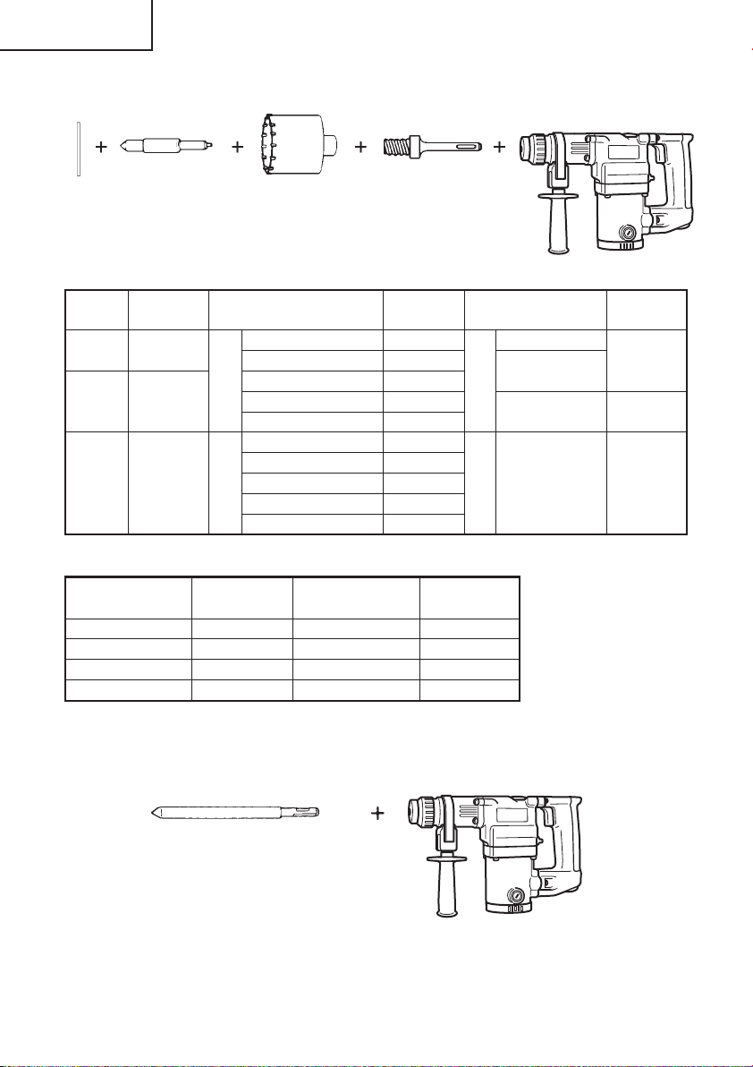
3. Large hole boring (Rotation + Striking)
Guide
Center pin
Plate
Center
Code No.
pin
––
(A) 982684 1-3/8" (35 mm) 982675 11-13/18"
(B) 982685 (B) 2-9/16" (65 mm) 982679 (B)
Core Bit
Core bit Shank
(SDS-plus shank)
Core bit (outer diameter) Core bit shank
63/64"(25 mm) 982672 Overall length
1-9/64" (29 mm) 982673 4-1/8" 303625
(A) 1-1/4" (32 mm) 982674 (A) (105 mm)
1-1/2" (38 mm) 982676 (300 mm)
1-25/32" (45 mm) 982677
1-31/32" (50 mm) 982678
3-5/32" (80 mm) 982680
3-17/32" (90 mm) 982681
Code No. Code No.
Guide plate
Core bit
(outer diameter)
1-1/4" (32 mm)
1-3/8" (35 mm)
1-1/2" (38 mm)
1-25/32" (45 mm)
Code No.
982686
982687
982688
982689
Core bit
(outer diameter)
1-31/32" (50 mm)
2-9/16" (65 mm)
3-5/32" (80 mm)
3-17/32" (90 mm)
Code No.
982690
982691
982692
982693
11-13/18"
(300 mm)
303626
303627
4. Demolishing operation (Striking only)
Bull point (Round type) (SDS-plus shank)
Code No. 303046
22
Page 23

5. Bolt placing operation with Chemical Anchor. (Rotation + Striking)
Standard socket
on the market
6. Drilling holes and driving screws (Rotation only)
䡬 Drill chuck, chuck adaptor and chuck wrench
(SDS-plus shank)
1/2" (12.7 mm) Chemical
Anchor Adapter
(Code No.303044)
3/4" (19 mm) Chemical
Anchor Adapter
(Code No. 303045)
English
Special screw
Code No. 981122
7. Drilling holes (Rotation only)
Drill chuck (13VLA)
(includes chuck wrench)
Code No. 950272
Chuck wrench
䡬 1/2" (13 mm) drill chuck ass’y (includes chuck wrench) and chuck (for drilling into steel
or wood).
Drill chuck (13 VLR)
(includes chuck
wrench)
Code No. 950275
Chuck wrench
Chuck adaptor (D)
(SDS-plus shank)
Code No. 303624
Chuck adaptor G
(SDS-plus shank)
Code No. 303623
23
Page 24

English
8. Driving Screws (Rotation only)
Bit No. Chuck adaptor (D)
(SDS-plus shank)
Code No. 303624
Phillips Driver Bit
Bit No. Screw Size Length Code No.
No.2 1/8" ~ 3/16" (3 – 5 mm) 31/32" (25 mm) 971511Z
No.3 1/4" ~ 5/16" (6 – 8 mm) 31/32" (25 mm) 971512Z
9. Dust collector (B)
Dust collector (B)
Code No. 306885
10. Hammer grease A
1.1 lbs (500 g) (in a can) Code No. 980927
0.15 lbs (70 g) (in a green tube) Code No. 308471
0.07 lbs (30 g) (in a green tube) Code No. 981840
NOTE: Specifications are subject to change without any obligation on the part of the
HITACHI.
24
Page 25

Français
INFORMATIONS IMPORTANTES DE SÉCURITÉ
Lire et comprendre toutes les précautions de sécurité, les avertissements et les instructions
de fonctionnement dans ce mode d’emploi avant d’utiliser ou d’entretenir cet outil motorisé.
La plupart des accidents causés lors de l’utilisation ou de l’entretien de l’outil motorisé
proviennent d’un non respect des règles ou précautions de base de sécurité. Un accident
peut la plupart du temps être évité si l’on reconnaît une situation de danger potentiel avant
qu’elle ne se produise, et en observant les procédures de sécurité appropriées.
Les précautions de base de sécurité sont mises en évidence dans la section “SECURITE”
de ce mode d’emploi et dans les sections qui contiennent les instructions de fonctionnement
et d’entretien.
Les dangers qui doivent être évités pour prévenir des blessures corporelles ou un
endommagement de la machine sont identifiés par AVERTISSEMENTS sur l’outil motorisé
et dans ce mode d’emploi.
NE JAMAIS utiliser cet outil motorisé d’une manière qui n’est pas spécifiquement
recommandée par HITACHI.
SIGNIFICATION DES MOTS D’AVERTISSEMENT
AVERTISSEMENT indique des situations potentiellement dangereuses qui, si elles sont
ignorées, pourraient entraîner la mort ou de sérieuses blessures.
PRECAUTION indique des situations dangereuses potentilles qui, si elles ne sont pas évitées,
peuvent entraîner de mineures et légères blessures ou endommager la machine.
REMARQUE met en relief des informations essentielles.
25
Page 26

Français
SECURITE
REGLES GENERALE DE SECURITE
AVERTISSEMENT: Lire et coxmprendre toutes les instructions.
Un non respect de toutes les instructions ci-dessous peut
entraîner une électrocution, un incendie et/ou de sérieuses
blessures personnelles.
CONSERVER CES INSTRUCTIONS
1. Zone de travail
(1) Garder la zone de travail propre et bien éclairée. Les établis mal rangés et les
zones sombres invitent aux accidents.
(2) Ne pas utiliser les outils motorisés dans une atmosphère explosive, telle qu’en
présence de liquides inflammables, de gaz ou de poussières. Les outils motorisés
créent des étincelles qui risquent d’enflammer la poussière ou les vapeurs.
(3) Tenir les spectateurs, les enfants et les visiteurs éloignés, lors de l’utilisation de
l’outil motorisé. Une distraction peut faire perdre le contrôle de la machine.
2. Sécurité électrique
(1) Les outils à double isolation sont équipés d’une fiche polarisée (une lame est plus
large que l’autre). Cette fiche ne pénétrera dans une prise secteur polarisée que
dans un sens. Si la fiche ne rentre pas complètement dans la prise, la retourner. Si
elle ne rentre toujours pas, contacter un électricien qualifié pour installer une prise
polarisée. Ne pas modifier la fiche d’aucune façon. La double isolation
le besoin d’un cordon d’alimentation à trois fils et d’un système d’alimentation
avec mises à la terre.
(2) Eviter tout contact corporel avec les surfaces mises à la terre telles que les
canalisations, les radiateurs, les réchauds et les réfrigérateurs. Il y a un risque
accru d’électrocution si son corps est mis à la terre.
(3) Ne pas exposer les outils motorisés à la pluie ou à l’humidité. De l’eau pénétrant à
l’intérieur de l’outil motorisé augmente le risque d’électrocution.
(4) Ne pas maltraiter le cordon d’alimentation. Ne jamais utiliser le cordon pour porter
les outils ou tirer sur la fiche du réceptacle. Garder le cordon à l’écart de la chaleur,
de l’huile, des arêtes coupantes ou des pièces en mouvement. Remplacer les
cordons endommagés immédiatement. Des cordons endommagés augmentent le
risque d’électrocution.
(5) Lors de l’utilisation d’un outil motorisé, utiliser un cordon de rallonge extérieur
marqué “W-A” ou “W”. Ces cordons sont prévus pour une utilisation extérieure et
réduisent les risques d’électrocution.
3. Sécurité personnelle
(1) Rester sur ses gardes, regarder ce que l’on fait et utiliser son sens commun lors de
l’utilisation d’un outil motorisé. Ne pas utiliser un outil en état de fatigue ou sous
l’influence de drogues, d’alcool ou de médicaments. Un moment d’inattention lors
de l’utilisation de l’outil motorisé peut entraîner de sérieuses blessures personnelles.
26
élimine
Page 27

Français
(2) S’habiller correctement. Ne pas porter des vêtements larges ou des bijoux. Attacher
les cheveux longs. Tenir ses cheveux, vêtements et ses gants éloignés des parties
mobiles. Les vêtements larges, les bijoux et les cheveux longs peuvent se prendre
dans les parties mobiles.
(3) Eviter tout démarrage accidentel. S’assurer que le l’interrupteur d’alimentation
est sur la position d’arrêt avant de brancher la machine. Transporter l’appareil
avec les doigts sur l’interrupteur d’alimentation ou brancher un outil avec
l’interrupteur sur la position marche invite aux accidents.
(4) Retirer les clefs d’ajustement ou les commutateurs avant de mettre l’outil sous
tension. Une clef qui est laissée attachée à une partie tournante de l’outil peut
provoquer une blessure personnelle.
(5) Ne pas trop présumer de ses forces. Garder en permanence une position et un
équilibre correct. Une position et un équilibre correct permettent un meilleur contrôle
de l’outil dans des situations inattendues.
(6) Utiliser un équipement de sécurité. Toujours porter une protection pour les yeux.
Utiliser un masque à poussière, des chaussures anti-dérapantes, un casque dur ou
des protections anti-bruit si nécessaire.
4. Utilisation de l’outil et entretien
(1) Utiliser un étau ou toutes autres façons de fixer et maintenir la pièce à usiner sur
une plate-forme stable. Tenir la pièce avec la main ou contre son corps est instable
et peut conduire à une perte de contrôle de l’outil.
(2) Ne pas forcer sur l’outil. Utiliser l’outil correct pour l’application souhaitée. L’outil
correct réalisera un meilleur et plus sûr travail dans le domaine pour lequel il a été
conçu.
(3) Ne pas utiliser un outil s’il ne se met pas sous ou hors tension avec un interrupteur.
Un outil qui ne peut pas être commandé avec un interrupteur est dangereux et doit
être réparé.
(4) Déconnecter la fiche de la source d’alimentation avant de réaliser tout ajustement,
changement d’accessoires ou pour ranger l’outil. De telles mesures de sécurité
réduisent le risque que l’outil ne démarre accidentellement.
(5) Ranger les outils inutilisés hors de la portée des enfants et des autres personnes
inexpérimentées. Les outils sont dangereux dans les mains de personnes
inexpérimentées.
(6) Conserver les outils avec soin. Garder les outils de coupe aiguisés et propres. Des
outils bien entretenus, avec des lames coupantes aiguisées risquent moins de se
gripper et sont plus faciles à contrôler.
(7) Vérifier les défauts d’alignement ou grippage des parties mobiles, les ruptures
des pièces et toutes les autres conditions qui peuvent affecter le fonctionnement
des outils. En cas de dommage, faire réparer l’outil avant de l’utiliser. Beaucoup
d’accidents sont causés par des outils mal entretenus.
(8) Utiliser uniquement les accessoires recommandés par le fabricant pur le modèle
utilisé. Des accessoires qui peuvent convenir à un outil, peuvent devenir dangereux
lorsqu’ils sont utilisés avec un autre outil.
5. Réparation
(1) La réparation de l’outil ne doit être réalisée uniquement par un réparateur qualifié.
Une réparation ou un entretien réalisé par un personnel non qualifié peut entraîner
des risques de blessures.
27
Page 28

Français
(2) Lors de la réparation d’un outil, utiliser uniquement des pièces de rechange
identiques. Suivre les instructions de la section d’entretien de ce mode d’emploi.
L’utilisation de pièces non autorisées ou un non respect des instructions d’entretien
peut créer un risque d’électrocution ou de blessures.
REGLES DE SECURITE SPECIFIQUES ET SYMBOLES
1. Tenir les outils par les surfaces de grippage lors de la réalisation d’opération où l’outil
de coupe risque d’entrer en contact avec des câbles cachés ou son propre cordon. Un
contact avec un fil “sous tension” mettra les parties métalliques de l’outil “sous tension”
et électrocutera l’utilisateur.
2. TOUJOURS porter des protections anti-bruit lors de sessions de travail prolongées.
Une exposition prolongée à un son de forte intensité peut
endommager l’ouïe de l’utilisateur.
3. NE JAMAIS toucher la mèche avec des mains nues après l’utilisation.
4. NE JAMAIS porter de gants faits d’une matière qui risque de s’enrouler, comme du
coton, de la laine, de la toile ou de la ficelle, etc.
5. TOUJOURS fixer la poignée latérale et tenir fermement le marteau rotatif.
6. NE JAMAIS toucher les parties mobiles.
NE JAMAIS placer ses mains, ses doigts ou toute autre partie de son corps près des
parties mobiles de l’outil.
7. NE JAMAIS utiliser l’outil sans que tous les dispositifs de sécurité ne soient en place.
NE JAMAIS faire fonctionner cet outil sans que tous les dispositifs et caractéristiques
de sécurité ne soient en place et en état de fonctionnement. Si un entretien ou une
réparation nécessite le retrait d’un dispositif ou d’une caractéristique de sécurité,
s’assurer de bien remettre en place le dispositif ou la caractéristique de sécurité avant
de recommencer à utiliser l’outil.
8. Utiliser l’outil correct
Ne pas forcer sur un petit outil ou accessoire pour faire le travail d’un outil de grande
puissance. Ne pas utiliser un outil pour un usage pour lequel il n’a pas été prévu: par
exemple, ne pas utiliser une scie circulaire pour couper des branches d’arbre ou des
bûches.
9. NE JAMAIS utiliser un outil motorisé pour des applications autres que celles spécifiées.
NE JAMAIS utiliser un outil motorisé pour des applications autres que celles spécifiées
dans le mode d’emploi.
10. Manipuler l’outil correctement
Utiliser l’outil de la façon indiquée dans ce mode d’emploi. Ne pas laisser tomber ou
lancer l’outil. NE JAMAIS permettre que l’outil soit utilisé par des enfants, des personnes
non familiarisées avec son fonctionnement ou un personnel non autorisé.
28
Page 29

Français
11. Maintenir toutes les vis, tous les boulons et les couvercles fermement en place.
Maintenir toutes les vis, tous les boulons et les couvercles fermement montés. Vérifier
leurs conditions périodiquement.
12. Ne pas utiliser les outils motorisés si le revêtement de plastique ou la poignée est
fendu.
Des fentes dans le revêtement ou la poignée peuvent entraîner une électrocution. De
tels outils ne doivent pas être utilisés avant d’être réparé.
13. Les lames et les accessoires doivent être fermement montés sur l’outil.
Eviter les blessures potentielles personnelles et aux autres. Les lames, les instruments
de coupe et les accessoires qui ont été montés sur l’outil doivent être fixés et serrés
fermement.
14. Garder propres les évents d’air du moteur
Les évents d’air du moteur doivent être maintenus propres de façon que l’air puisse
circuler librement tout le temps. Vérifier les accumulations de poussière fréquemment.
15. Utiliser l’outil motorisé à la tension nominale.
Utiliser l’outil motorisé à la tension spécifiée sur sa plaque signalétique.
Si l’on utilise l’outil motorisé avec une tension supérieure à la tension nominale, il en
résultera une rotation anormalement trop rapide du moteur et cela risque
d’endommager l’outil et le moteur risque de griller.
16. NE JAMAIS utiliser un outil défectueux ou qui fonctionne anormalement.
Si l’outil n’a pas l’air de fonctionner normalement, fait des bruits étranges ou sans cela
paraît défectueux, arrêter de l’utiliser immédiatement et le faire réparer par un centre
de service Hitachi autorisé.
17. NE JAMAIS laisser fonctionner l’outil sans surveillance. Le mettre hors tension.
Ne pas abandonner l’outil avant qu’il ne soit complètement arrêté.
18. Manipuler l’outil motorisé avec précaution.
Si un outil motorisé tombe ou frappe un matériau dur accidentellement, il risque d’être
déformé, fendu ou endommagé.
19. Ne pas essuyer les parties en plastique avec du solvant.
Les solvants comme l’essence, les diluants, la benzine, le tétrachlorure de carbone et
l’alcool peuvent endommager et fissurer les parties en plastique. Ne pas les essuyer
avec de tels solvants.
Essuyer les parties en plastique avec un chiffon doux légèrement imbibé d’une solution
d’eau savonneuse et sécher minutieusement.
20. TOUJOURS porter des lunettes de protection qui respectent les dernières révisions du
Standard ANSI Z87.1.
21. TOUJOURS vérifier s’il y a des objets encastrés par exemple des fils électriques.
Le fait de toucher avec l’outil un fil ou un câble électrique sous tension encastré dans le
mur risque de provoquer une décharge électrique.
Vérifier s’il y des objets encastrés, par exemple un câble électrique, dans le mur, le
plancher ou le plafond avant d’y commencer le travail.
29
Page 30

Français
22. Définitions pour les symboles utilisés sur cet outil
V ............ volts
Hz .......... hertz
A ............ ampères
o ........... vitesse sans charge
n
W ........... watt
........... Construction de classe II
---/min ... tours par minute
.......... Courant alternatif
DOUBLE ISOLATION POUR UN FONCTIONNEMENT PLUS
SUR
Pour assurer un fonctionnement plus sûr de cet outil motorisé, HITACHI a adopté une
conception à double insolation. “Double isolation” signifie que deux systèmes d’isolation
physiquement séparés ont été utilisés pour isoler les matériaux conducteurs d’électricité
connectés à l’outil motorisé à partir du cadre extérieur manipulé par l’utilisateur. C’est
pourquoi, le symbole “
sur l’outil motorisé ou sur la plaque signalétique.
Bien que ce système n’ait pas de mise à terre extérieure, il est quand même nécessaire de
suivre les précautions de sécurité électrique données dans ce mode d’emploi, y-compris
de ne pas utiliser l’outil motorisé dans un environnement humide.
Pour garder le système de double isolation effectif, suivre ces précautions:
䡬 Seuls les CENTRES DE SERVICE AUTORISES HITACHI peuvent démonter et remonter
cet outil motorisé et uniquement des pièces de rechange HITACHI garanties d’origine
doivent être utilisées.
䡬 Nettoyer l’extérieur de l’outil motorisé uniquement avec un chiffon doux légèrement
imbibé d’une solution savonneuse et essuyer minutieusement.
Ne jamais utiliser des solvants, de l’essence ou des diluants sur les parties en plastique;
sinon le plastique risquerait de se dissoudre.
” ou les mots “Double insulation” (double isolation) apparaissent
CONSERVER
CES INSTRUCTIONS
ET
LES METTRE A LA DISPOSITION
DES AUTRES UTILISATEURS
ET
PROPRIETAIRES DE CET OUTIL!
30
Page 31

Français
DESCRIPTION FONCTIONNELLE
REMARQUE: Les informations contenues dans ce mode d’emploi sont conçues pour assister
l’utilisateur dans une utilisation sans danger et un entretien de l’outil motorisé.
NE JAMAIS utiliser ni entreprendre une révision de l’outil sans avoir d’abord
lu et compris toutes les instructions de sécurité contenues dans ce manuel.
Certaines illustrations dans ce mode d’emploi peuvent montrer des détails
ou des accessoires différents de ceux de l’outil motorisé utilisé.
NOM DES PARTIES
Foret de
perçage
Capuchon
avant
Quenouille
Poignée
laterale
Attache
coulissante
Plaque
signalétique
Carter
Fig. 1
Interrupteur
Poignee
Sélecteur
Bouchon de charbon
(Al’interieur du
couvercle de queue)
SPECIFICATIONS
Moteur Moteur série monophasé à collecteur
Source d’alimentation Secteur, 120V 60 Hz, monophasé
Courant 5,7A
Capacité béton: 1/8" – 1" (3,4mm – 25mm)
acier: 1/2" (13mm)
bois: 1-1/4" (32mm)
Vitesse sans charge 0 – 1100/min.
Vitesse de percussion à pleine charge
Poids 7,5 lbs (3,4 kg)
0 – 4000/min.
31
Page 32

Français
ASSEMBLAGE ET FONCTIONNEMENT
APPLICATIONS
Par action combinée de rotation et de frappe
䡬 Perçage de trous d’ancrage
䡬 Perçage de trous dans béton
䡬 Perçage de trous dans une tuile
Par action de rotation uniquement
䡬 Perçage de l’acier ou du bois (avec accessoires en option)
䡬 Serreage de vis mécaniques et de vis à bois.
(avec accessoires en option)
AVANT L’UTILISATION
1. Source d’alimentation
S’assurer que la source d’alimentation qui doit être utilisée est conforme à la source
d’alimentation requise spécifiée sur la plaque signalétique du produit.
2. Interrupteur d’alimentation
S’assurer que l’interrupteur est sur la position OFF (arrêt). Si la fiche est connectée sur
une prise alors que l’interrupteur est sur la position ON (marche), l’outil motorisé
démarrera immédiatement risquant de causer de sérieuses blessures.
3. Cordon prolongateur
Quand la zone de travail est éloignée de la source d’alimentation, utiliser un cordon
prolongateur d’épaisseur et de capacité nominale suffisante. Le cordon prolongateur
doit être aussi court que possible.
AVERTISSEMENT:
Tout cordon endommagé devra être remplacé ou réparé.
4. Vérifier la prise
Si la prise reçoit la fiche avec beaucoup de jeu, elle doit être réparée. Contacter un
électricien licencié pour réaliser les réparations nécessaires.
Si une telle prise défectueuse est utilisée, elle peut causer une surchauffe entraînant
des dangers sérieux.
5. Vérification des conditions d’environnement
Vérifier que l’état de l’aire de travail est conforme aux précautions.
32
Page 33

Français
6. Montage du foret de perçage
(Fig. 2)
(1) Pour fixer un foret de perçage (tige SDS plus),
tirer complètement l’attache coulissante dans
le sens de la flèche, comme indiqué sur la Fig.
2, puis insérer le foret tout en le faisant tourner
jusqu’à ce qu’il atteigne le fond.
(2) Lorsque l’attache coulissante est relâchée, le
foret est fixé.
(3) Pour retirer le foret de perçage, tirer
complètement l’attache coulissante dans le
sens de la flèche et sortir le foret.
Elément de la
tige SDS plus
Foret de
perçage
Capuchon
avant
Attache
coulissante
Fig. 2
7. Lors de l’installation de la capuchon à
poussière ou du collecteur de de
poussière (B) (accessoirs en option) (Fig.
Godet à
poussière
3, Fig. 4)
Lors de l’utilisation du marteau rotatif en
position verticale alors que l’adaptateur de
récupération de poussière est enlevé, fixar la
capuchon à poussière ou le collecteur à
poussière (B) pour récupérer la poussière et
autres particules pour une utilisation plus
facile.
䡬 Pose de la capuchone à poussière
Utiliser la capuchone à poussière en la fixant
au foret comme montré dans la Fig. 3.
Lors de l’utilisation d’ un foret avec un
diamètre plus grand, agrandir le trou central
de la capuchon à poussière avec ce marteau
perforateur.
䡬 Pose du collecteur à poussière (B)
Lors de l’utilisation du collecteur à poussière
(B), l’insérer par le bout du foret en l’alignant
avec la rainure sur la poignée. (Fig. 4)
PRECAUTION:
䢇 La capuchon à poussière et le collecteur à poussière (B) ne sont destinés à être utilisés
que lors du perçage de béton. Ne pas les utiliser lors du perçage de pièces en bois ou
métalliques.
䢇 Insérer le collecteur à poussière (B) à fond dans le mandrin de l’appareil principal
particules pour ne utilisation pluse facile.
䢇 Lors de la mise sous tension du marteau rotatif alors le collecteur à poussière (B) est
détaché de la surface en béton, le collecteur à poussière (B) va tourner en même temps
que le foret. Ne bien activer l’interrupteur de mise sous tension qu’après avoir appuyé
le collecteur à poussière (B) sur la surface en béton. Si le collecteur à poussière (B) est
utilisé avec un foret de plus de 7-15/32" (190 mm) de longueur totale, il ne peut pas
toucher la surface en béton et tournera. De ce fait, utiliser un foret de 6-17/32" (166 mm),
Collecteur à poussière (B)
Fig. 3
Fig. 4
33
Page 34

Français
6-19/64" (160 mm) ou 4-21/64" (110 mm) de longueur totale.
䢇 Vider les particules dans le collecteur à poussière (B) chaque deux ou trois trous percés.
䢇 Remettre en place le foret après avoir enlevé le collecteur à poussière (B).
8. Sélection de la mèche pour visseuse
Les têtes de vis ou les mèches seront endommagées si une mèche inappropriée au
diamètre de la vis n’est pas employée pour enfoncer la vis.
UTILISATION
PRECAUTION:
䢇 Pour éviter tout accident, s’assurer que l’interrupteur est sur la position d’arrêt et que
la fiche du cordon d’alimentation est débranchée avant de poser ou de déposer un
forêt ou un accessoire similaire. L’interrupteur d’alimentation doit toujours se trouver
sur la position d’arrêt pendant une pause et après un travail.
1. Fonctionnement de l’interrupteur
La vitesse de rotation du foret de perçage peut être réglée suivant la force avec laquelle
on appuie sur l’interrupteur à détente. La vitesse est faible si on exerce une légère
pression et augmente si la pression est plus forte. On peut obtenir un fonctionnement
continu en pressant la détente et en relâchant le cliquet d’arrêt.
2. Rotation + frappe
Cette perceuse à percussion peut être mise
sur le mode de rotation et frappe en tournant
le sélecteur à fond dans le sens inverse des
aiguilles d’une montre vers le repère . (Fig.
5)
(1) Monter le foret de perçage.
(2) Tirer l’interrupteur de déclenchement après
avoir appliqué la pointe du foret sur la position
de perçage désirée. (Fig. 6)
(3) Il n’est pas du tout nécessaire d’appliquer une
forte pression sur le marteau rotatif. Il suffit
d’appliquer une légère pression de manière à
ce que la poussière et les éclats soient
déchargés progressivement.
Fig. 5
Sélecteur
PRECAUTION:
䢇 Quand le foret de perçage touche une poutre
en fer, la mèche s’arrête immédiatement et
la perceuse réagit en tournant. Par
conséquent, tenir fermement la poignée
principale et la poignée latérale, comme
indiqué à la Fig. 6.
34
Fig. 6
Page 35

Français
3. Rotation seulement
Cette perceuse à percussion peut être mise
sur le mode de rotation uniquement en
tournant le sélecteur à fond dans le sens des
aiguilles d’une montre vers le repère
7)
Pour percer du bois ou du métal en utilisant
le mandrin porte-foret et le raccord de
mandrin (accessoire en option), procéder de
la manière suivante.
Mise en place de mandrin porte-foret et du
raccord de mandrin: (Fig. 8)
(1) Fixer le mandrin porte-foret sur le raccord.
(2) L’élément de la tige SDS est identique au foret
de perçage. Se reporter à “Montage du foret
de perçage” pour le fixer.
PRECAUTION:
䢇 Si l’on applique une force excessive, cela donnera un travail bâclé et abîmera la pointe
du foret de perçage, réduisant ainsi la durée de service de le marteau rotatif.
䢇 La pointe du foret de perçage risque de se casser quand on dégage la perceuse coincée
d’un trou qui vient d’être percé. Par conséquent, pour dégager la perceuse il est
important de faire très attention et de relâcher la pression ou de tourner le foret dans
le sens contraire des aiguilles d’une montre.
䢇 Ne pas essayer de percer des trous d’ancrage ou des trous dans le béton quand la
machine est réglée sur rotation seulement.
䢇 Ne pas essayer d’utiliser le marteau rotatif pour les fonctions de rotation et de frappe
quand le mandrin porte-foret et le raccord de mandrin sont montés sur la machine.
Cela risquerait d’abréger considérablement la durée de service de chaque élément de
la perceuse.
4. Lors du vissage des vis machine (Fig. 9)
Tout d’abord, insérer la pièce dans la prise à
l’extrémité de l’adaptateur (D) de mandrin.
Ensuite, monter l’adaptateur (D) de mandrin
sur l’appareil principal en utilisant les
procédures décrites en 6 (1), (2), (3). Mettre la
pointe de la pièce dans les fentes de la tête de
vis, maintenir l’appareil principal et visser.
. (Fig.
Mandrin porte-foret
Raccord de
mandrin
Mèche
Prise
Raccord (D)
de mandrin
Fig. 7
Capuchon avant
Elément de la
tige SDS plus
Fig. 8
Sélecteur
Attache
coulissante
Capuchon
avant
Attache
coulissante
Fig. 9
35
Page 36

Français
PRECAUTION:
䢇 Faites attention de ne pas prolonger la durée d’enfoncement plus qu’il n’est nécessaire,
sinon les vis pourraient être endommagées suite à la force excessive utilisée.
䢇 Appliquez le marteau rotatif perpendiculairement par rapport à la tête de la vis lors de
l’enfoncement de la vis; sinon la tête de la vis ou la mèche seront endommagées, ou la
force d’entraînement ne sera pas entièrement transférée à la vis.
䢇 Ne pas essayer d’utiliser le marteau rotatif en fonction de rotation et percussion lorsque
l’adaptateur de mandrin et la pièce sont attachés.
5. Enfoncement de vis à bois (Fig. 9)
(1) Sélection d’une mèche appropriée
Utilisez des vis à tête cruciforme, autant que possible étant donné que la mèche glisse
souvent de la tête des vis ordinaires.
(2) Enfoncement de vis à bois
䡬 Avant d’enfoncer des vis à bois, préparez d’abord des trous appropriés aux vis utilisées
dans le bois. Appliquez la mèche aux fentes de la tête de la vis et enfoncez la vis dans
le bois en douceur.
䡬 Après avoir fait tourner le marteau rotatif à petite vitesse pendant un moment jusqu’à
ce que la vis à bois soit partiellement enfoncée, pressez le trigger plus fortement afin
d’obtenir la force d’entraînement maximale.
PRECAUTION:
䢇 Ne manquez pas de prendre en considération
la dureté du bois quand vous préparez un trou
approprié à recevoir la vis à bois. Si le trou
est trop petit ou pas assez profond, ce qui
demande beaucoup de force pour y enfoncer
la vis, il se peut que le filet de la vis de bois en
soit endommagé.
6. Utilisation de l’arràtoir (Fig. 10)
(1) Desserrer le bouton de la poignée latérale, et
insérer la quenouille dans l’orifice de montage
de la poignée latérale.
(2) Régler la position de la quenouille en fonction
de la profondeur de l’orifice, et serrer le
bouton à fond.
7. Comment utiliser la mèche (queue
conique) et le raccord de queue conique
(1) Monter le raccord de queue conique sur le
marteau rotatif à percussion. (Fig. 11)
(2) Fixer la mèche (queue conique) sur le raccord
de queue conique. (Fig. 11)
(3) Mettre l’interrupteur sur la position de marche
(ON) et percer un trou de la profondeur
voulue.
Quenouille
Foret de
perçage
Raccord de
queue conique
Orifice de
montage
Fig. 10
Attache
coulissante
Fig. 11
Poignée
laterale
Capuchon
avent
36
Page 37

Français
(4) Pour retirer la mè che (queue conique),
introduire la clavette dans la fente du raccord
de queue conique et frapper la tête de la
clavette avec un marteau alors que le perceuse
est placée sur le support. (Fig. 12)
Clavette
Raccord de
queue conique
8. Utilisation de la poignée latérale
Si l’on désire modifier la position de la poignée
latérale, tourner le manche de la poignée
latérale dans le sens inverse des aiguilles
d’une montre pour desserrer la poignée, puis
la fixer solidement.
Support
PRECAUTION:
Lors du perçage d’un trou, il peut arriver que l’outil se mette à tourner sous l’effet de
la réaction au moment de la pénétration d’un mur de béton et/ou lorsque la pointe de
la lame entre en contact avec la barre béton.
Fixer solidement la poignée latérale et tenir l’outil des deux mains. Si l’outil n’est pas
tenu solidement, cela risque de provoquer un accident.
Fig. 12
COMMENT UTILISER LA COURONNE (POUR UNE CHARGE LEGERE)
Utiliser la couronne pour percer de grands trous.
L’utiliser avec le goujon central et la queue de
couronne fournis en tant qu’accessoires en option.
1. Montage
PRECAUTION:
䢇 S’assurer que l’interrupteur est sur la position
d’arrêt (OFF) et débrancher l’outil.
(1) Monter la couronne sur la queue de couronne.
(Fig. 13)
Graisser le filetage da la queue de couronne
afin de faciliter le démontage.
(2) Monter la queue de couronne sur le marteau
rotatif à percussion. (Fig. 14)
(3) Introduire la guijon central dans la plaque de
guidage jusqu’à ce qu’il arrête.
Couronne
Filetage
Queue de
couronne
Fig. 13
Fig. 14
37
Page 38

Français
(4) Engager la plaque de guidage dans la
couronne et tourner la plaque de guidage à
gauche ou à droite de manière à ce qu’elle à
ce qu’elle ne puisse pas tomber, même si elle
orientée vers le bas. (Fig. 15)
2. Perçage (Fig. 16)
(1) Brancher la perceuse.
(2) Un ressort est placé dans le goujon central.
Appuyer lég èrement l’ outil
perpendiculairement contre le mur ou le
plancher. Toute la surface de la couronne doit
être en contact avec le mur ou le plancher.
Mettre en marche.
(3) Quand on a percé sur une profondeur
d’environ 3/16" (5 mm), la position du trou est
déterminée. Continuer à percer après avoir
retiré le goujon central et la plaque de guidage
de la couronne.
(4) Si l’on applique une force excessive, cela
donnera un travail bâclé et abîmera la pointe
du foret de perçage, réduisant ainsi la durée
de service du marteau rotatif.
PRECAUTION:
䢇 Quand on retire le goujon central et la plaque
de guidage, mettre l’interrupteur sur la
position d’arrêt (OFF) et débrancher la
perceuse.
Goujon
central
Couronne
Plaque de
guidage
Bout de
couronne
Fig. 15
Fig. 16
3. Démontage (Fig. 17)
Une autre méthode consiste à retirer la queue
de la couronne du marteau rotatif à frapper
fortement la tête de la queue de la couronne
deux ou trois fois avec un marteau, tout en
maintenant la couronne. Cela aura pour effet
de desserrer le filetage et on pourra retirer la
couronne.
38
Queue de couronne
Fig. 17
Page 39

Français
ENTRETIEN ET INSPECTION
AVERTISSEMENT: S’assurer de mettre l’interrupteur d’alimentation sur la
position OFF et de déconnecter la fiche de la prise secteur
avant l’entretien et l’inspection de la meuleuse.
1. Contrôle du foret de perçage
Etant donné que l’utilisation d’une mèche usée entraînera un mauvais fonctionnement
du moteur et une diminution de l’efficacité, remplacez la mèche usée par une neuve ou
aiguisez-la immédiatement et dès que vous notez une certaine usure.
2. Inspection des vis
Inspecter régulièrement toutes les vis et s’assurer qu’elles sont correctement serrées.
Si l’une des vis était desserrée, la resserrer immédiatement.
AVERTISSEMENT: Utiliser la marteau rotatif avec des vis desserrées est
extrêmement dangereux.
3. Entretien du moteur:
Le bobinage de l’ensemble moteur est le “coeur” même de l’outil électro-portatif. Veiller
soigneusement à ce que ce bobinage ne soit pas endommagé et/ou mouillé par de
l’huile ou de l’eau.
4. Contrôle des balais en carbone (Fig. 18)
Le moteur utilise des balais en carbone qui sont des pièces qui s’usent. Quand ils sont
usés ou près de la “limite d’usure”, il pourra en résulter un mauvais fonctionnement
du moteur.
Quand le moteur est équipé d’un balai en carbone à arrêt automatique, il s’arrêtera
automatiquement. Remplacez alor les balais en carbone par des nouveaux et ayant les
mêmes numéros que ceux montré sur la figure. En outre, toujours tenir les balais propres
et veiller à ce qu’ils coulissent librement dans les supports.
PRECAUTION:
Utiliser la polisseuse avec un balai en carbone qui est usé au-delà de la limite d’usure
endommagera le moterur.
Limite d’usure
No. du balai
a
en carbone
Balai de charbon 0,2"
ordinaire (5 mm)
No. du balai en carbone
a
0,47"
(12 mm)
Fig. 18
REMARQUE: Utiliser le balai en carbone HITACHI No. indiqué sur la Fig. 18.
Balai de charbon
à arrêt automatique
— 70
21
39
Page 40

Français
䡬 Remplacement du balais en carbone
Desserrer la vis de fixation et enlever le couvercle de la queue. Enlever la chapeau de
balai et la balai en carbone. Après avoir remplacé le balai en carbone, serrer fermement
le chapeau du balai et installer le couvercle avec deux vis de fixation.
5. Comment remplacer la graisse
Cette machine est de contruction entièrement hermétique pour la protéger contre la
poussière et pour éviter les fuites de lubrifiant. Elle peut donc être utilisée sans
lubrification pendant longtemps. Remplacer la graisse comme indiqué ci-dessous.
䡬 Période de remplacement
Contrôler la quantité de graisse lors du remplacement de la brosse de carbone. (Voir
l'élément 4 de la section MAINTENANCE ET INSPECTION.) Se procurer la graisse chez
l’Agence de Service Autorisée HITACHI la plus proche. Procéder au remplacement.
䡬 Plein de graisse
PRECAUTION:
Avant de faire le plein de la graisse, fermer l’interrupteur et débrancher l’outil de la
prise de courant.
(1) Démonter le bouchon d’huile et essuyer
complètement la vieille graisse à l’intérieur.
(Fig. 19)
(2) Appliquer 17,5 g (la quantité standard pour
recouvrir la tige de connexion) de graisse pour
marteau électrique Hitachi A dans le carter.
(3) Après avoir remplacé la graisse, remonter
fermement le bouchon d’huile. A ce moment,
en pas endommager ni desserrer le joint
torique.
REMARQUE: La graisse pour marteau électrique Hitachi A est du type à viscosité faible. Si
nécessaire, se procurer la graisse chez un agent réparateur Hitachi agréé;
adressez-vous à votre Agent de Service Autorisé Hitachi pour vous en procurer
de nouveau.
Bouchon d’huile
Fig. 19
6. Entretien et reparation
Tous les outils motorisés de qualité auront éventuellement besoin d’une réparation ou
du remplacement d’une pièce à cause de l’usure normale de l’outil. Pour assurer que
seules des pièces de rechange autorisées seront utilisées, tous les entretiens et les
réparations doivent être effectués uniquement par UN CENTRE DE SERVICE HITACHI
AUTORISE.
40
Page 41

Français
ACCESSOIRES
AVERTISSEMENT: TOUJOURS utiliser UNIQUEMENT des pièces de rechange
et des accessoires HITACHI. Ne jamais utiliser de pièce de
rechange ou d’accessoires qui ne sont pas prévus pour être
utilisé avec cet outil. En cas de doute, contacter HITACHI pour
savoir si une pièce de rechange ou un accessoire particulier
peuvent être utilisés en toute sécurité avec votre outil.
L’utilisation de tout autre attachement ou accessoire peut
être dangereux et peut causer des blessures ou des
dommages mécaniques.
REMARQUE: Les accessoires sont sujets à changement sans obligation de la part de
HITACHI.
ACCESSOIRES STANDARD
(1) Valise (Plastique) (No. de code 318307) .......................................................................... 1
(2) Poignée latérale (No. de code 980939) ............................................................................ 1
(3) Quenouille (No. de code 980906) ..................................................................................... 1
(4) Capuchon anti poussière (No. de code 971787) ............................................................. 1
ACCESSOIRES SUR OPTION....... vendus séparément
1. Perçage de trous d’ancrage (Rotation + Frappe)
䡬 Foret de perçage (Tige fine)
(1) Foret de perçage
(Tige fine)
(1) Foret de perçage (Tige fine)
Diamètre extérieur Longueur effective Longueur totale No. de code No. de code
1/8" 1-25/32" 3-35/64"
(3,4mm) (45mm) (90mm)
9/64" 1-25/32" 3-35/64"
(3,5mm) (45mm) (90mm)
(2) Adaptateur pour
tige fine
(Tige SDS plus)
(2) Adaptateur
pour tige fine
306369
306370
306368
41
Page 42

Français
䡬 Foret de perçage (queue conique) et raccord de queue conique
(1) Foret de perçage
(queue conique)
(2) Raccord de queue
conique (Tige SDS plus)
Clavette (No. de code 944477)
Dia. externe No. de code
7/16"
(11 mm)
31/64"
(12,3 mm)
1/2"
(12,7 mm)
9/16"
(14,3 mm)
73/128"
(14,5 mm)
11/16"
(17,5 mm)
27/32"
(21,5 mm)
944460
944461
993038
944462
944500
944463
944464
Tupe de cône No. de code Foret de perçage utilisé
Foret de
perçage
Cône Morse
(No. 1)
Cône Morse
(No. 2)
Cône en A 303619
Cône en B 303620
303617
303618 27/32" (21,5 mm)
utilisé
(queue
conique)
Foret de
perçage
utilisé (queue
conique)
Le raccord de queue conique pour
cône en forme de A ou B est fourni
en tant qu’accessoire en option,
mais le foret de perçage qui lui
correspond n’est pas fourni.
䡬 Mandrin de 13 mm du marteau rotatif
Pour perçage lors de l’utilisation d’un foret à corps droit pour un perçage à
impact avec le marteau rotatif.
7/16" (11 mm)
31/64" (12,3 mm)
1/2" (12,7 mm)
9/16" (14,3 mm)
73/128" (14,5 mm)
11/16" (17,5 mm)
Mèche à queue droite
pour application de
perceuse à percussion
Mandrin de 13 mm du
marteau rotatif
(Tige SDS plus)
(avec clé de mandrin)
Désignation No. de code
Mandrin de 13 mm du martean rotatif 303332
Clé de mandrin 303334
Capuchon en caoutchouc 303335
42
Clé de mandrin
Page 43

2. Ancrage de chasse (Rotation + Frappe)
Régleur d’ancrage
(pour fixation d’ancrage)
(Tige SDS Plus)
<Type à cale extérieure avec vis femelle>
Dimension W 1/4" W 5/16" W 3/8"
de l’ancrage (6,3 mm) (8 mm) (9,5 mm)
Longueur totale
No. de code 302976 302975 303621 302974
10-15/64" 10-15/64" 6-19/64" 10-15/64"
(260 mm) (260 mm) (160 mm) (260 mm)
<Type à cale intérieure avec vis sans tête>
Dimension W 1/4" W 5/16" W 3/8"
de l’ancrage (6,3 mm) (8 mm) (9,5 mm)
Longueur totale
No. de code 302979 302978 303622 302977
10-15/64" 10-15/64" 6-19/64" 10-15/64"
(260 mm) (260 mm) (160 mm) (260 mm)
Français
Raccord de mise en place de
la fixation (pour marteau)
<Type à cale extérieure avec
vis femelle>
Dimension de l’ancrage
W1/4"
(6,3 mm)
W5/16"
(8 mm)
W3/8"
(9,5 mm)
W1/2"
(12,7 mm)
W5/8"
(15,9 mm)
No. de code
971794
971795
971796
971797
971798
<Type à cale intérieure avec
vis sans tête>
Dimension de l’ancrage
W1/4"
(6,3 mm)
W5/16"
(8 mm)
W3/8"
(9,5 mm)
W1/2"
(12,7 mm)
W5/8"
(15,9 mm)
No. de code
971799
971800
971801
971802
971803
43
Page 44

Français
3. Perçage de trou à large diamètre (Rotation + Frappe)
(Plaque
centrale
de
Goujon Couronne
Queue de
couronne
(Tige SDS plus)
guidage)
Goujon
––
(A) 982684 1-3/8" (35 mm) 982675 11-13/18"
(B) 982685 (B) 2-9/16" (65 mm) 982679 (B)
No. de Couronne No. de Queue de No. de
code (diamètre externe) code couronne code
63/64"(25 mm) 982672
1-9/64" (29 mm) 982673 4-1/8"
(A) 1-1/4" (32 mm) 982674 (A) (105 mm)
1-1/2" (38 mm) 982676 (300 mm)
1-25/32" (45 mm) 982677
1-31/32" (50 mm) 982678
3-5/32" (80 mm) 982680
3-17/32" (90 mm) 982681
Plaque centrale de guidage
Couronne
(diamètre externe)
1-1/4" (32 mm)
1-3/8" (35 mm)
1-1/2" (38 mm)
1-25/32" (45 mm)
No. de code
982686
982687
982688
982689
Couronne
(diamètre externe)
1-31/32" (50 mm)
2-9/16" (65 mm)
3-5/32" (80 mm)
3-17/32" (90 mm)
No. de code
982690
982691
982692
982693
Longueur hors
tout
11-13/18"
(300 mm)
303625
303626
303627
4. Travail de démolissage (Frappe uniquement)
Pointe de broyage (type rond)
(Tige SDS plus)
No. de code 303046
44
Page 45

5. Mise en place du booulon pour d’ancre chimique (Rotation + Frappe)
Français
(Price)
(Tige SDS Plus)
1/2" (12.7 mm) Raccord
d’ancre chimique
(No. de code 303044)
3/4" (19 mm) Raccord
d’ancre chimique
(No. de code 303045)
6. Perçage de trous et insertion des vis (Rotation seulement)
䡬 Mandrin porte-foret, raccord (G) de mandrin, vis spéciale et clé de mandrin
vis spéciale
No. de code
981122
Mandrin porte-foret
(13 VLR)
(y compris la clé
de mandrin)
No. de code 950275
Raccord (G) de
mandrin
(Tige SDS
plus)
No. de code
303623
Clé de mandrin
7. Perçage de trous (Rotation seulement)
Mandrin porte-foret
(13VLA)
(y compris la clé
de mandrin)
No. de code 950272
Raccord (D) de
mandrin
(Tige SDS-Plus)
No. de code
303624
Clé de mandrin
䡬 Ensemble du mandrin porte-foret de 13 mm (y compris la clé de mandrin) et mandrin
(pour percer l’acier ou le bois).
45
Page 46

Français
8. Vis d’entraînement (Rotation uniquement)
No. de mèche Raccord (D) de
mandrin
(Tige SDS plus)
No. de code
303624
Embout de vissage Phillips
N
o. de mèche dimension de vis Longueur No. de code
No.2 1/8" ~ 3/16" (3 – 5 mm) 31/32" (25 mm) 971511Z
No.3 1/4" ~ 5/16" (6 – 8 mm) 31/32" (25 mm) 971512Z
9. Collecteur à poussière (B)
Collecteur à poussière (B)
No. de code 306885
10. Graisse A pour marteau
1,1 lbs (500 g) (en boîte) No. de code 980927
0,15 lbs (70 g) (en tube vert) No. de code 308471
0,07 lbs (30 g) (en tube vert) No. de code 981840
REMARQUE: Les spécifications sont sujettes à modification sans aucune obligation de la
part de HITACHI.
46
Page 47

Español
INFORMACIÓN IMPORTANTE SOBRE SEGURIDAD
Antes de utilizar o de realizar cualquier trabajo de mantenimiento de esta herramienta
eléctrica, lea y comprenda todas las precauciones de seguridad, advertencias e instrucciones
de funcionamiento de este Manual de instrucciones.
La mayoría de los accidentes producidos en la operación y el mantenimiento de una
herramienta eléctrica se deben a la falta de observación de las normas o precauciones de
seguridad. Los accidentes normalmente podrán evitarse reconociendo una situación
potencialmente peligrosa a tiempo y siguiendo los procedimientos de seguridad apropiados.
Las precauciones básicas de seguridad se describen en la sección “SEGURIDAD” de este
Manual de instrucciones y en las secciones que contienen las instrucciones de operación y
mantenimiento.
Para evitar lesiones o el daño de la herramienta eléctrica, los riesgos están identificados
con ADVERTENCIAS en dicha herramienta y en este Manual de instrucciones.
No utilice NUNCA esta herramienta eléctrica de ninguna forma que no esté específicamente
recomendada por HITACHI.
SIGNIFICADO DE LAS PALABRAS DE SEÑALIZACIÓN
ADVERTENCIA indica situaciones potencialmente peligrosas que, si se ignoran, pueden
resultar en la muerte o en lesiones de gravedad.
PRECAUCIÓN indica situaciones potencialmente peligrosas que, de no evitarse, pueden
resultar en lesiones menores o moderadas, o causar daños en la herramienta eléctrica.
NOTA acentúa información esencial.
47
Page 48

Español
SEGURIDAD
NORMAS GENERALES DE SEGURIDAD
ADVERTENCIA: Lea y entienda todas las instrucciones.
Si no sigue las instrucciones indicadas a continuación, pueden
producirse descargas eléctricas, incendios, y/o lesiones serias.
GUARDE ESTAS INSTRUCCIONES.
1. Área de trabajo
(1) Mantenga el área de trabajo limpia y bien iluminada. Los bancos de trabajo
desordenados y las áreas obscuras pueden conducir a accidentes.
(2) No utilice la herramienta en atmósferas explosivas, como en presencia de líquidos
inflamables, gases, o polvo. La herramienta eléctrica crea chispas que pueden
incendiar polvo o gases.
(3) Mantenga alejadas a otras personas, niños o visitantes, cuando utilice la
herramienta eléctrica. Las distracciones pueden hacer que pierda el control de la
herramienta.
2. Seguridad eléctrica
(1) Las herramientas eléctricas con aislamiento doble poseen un enchufe polarizado
(una cuchilla es más ancha que la otra.) Este enchufe encajará en un tomacorriente
polarizado de una sola forma. Si el enchufe no entra completamente en el
tomacorriente, invierta su sentido de inserción. Si sigue sin entrar, póngase en
contacto con un electricista cualificado para que le instale un tomacorriente
polarizado. No cambie nunca el enchufe. El aislamiento doble
necesidad de un cable de alimentación de tres conductores, uno para puesta a
tierra, y del sistema de alimentación con puesta a tierra.
(2) Evite el contacto con superficies con puesta a tierra, tales como tubos, radiadores,
hornos, y refrigeradores. Si toca tierra, existe el peligro de que reciba una descarga
eléctrica.
(3) No exponga la herramienta eléctrica a la lluvia ni a la humedad. La entrada de
agua en la herramienta eléctrica aumentará el riesgos de descargas eléctricas.
(4) No maltrate el cable de alimentación. No utilice nunca el cable de alimentación
para transportar la herramienta ni para desconectarla del tomacorriente. Mantenga
el cable alejado del calor, aceite, bordes cortantes, o partes móviles. Reemplace
inmediatamente cualquier cable dañado. Un cable dañado puede ser la causa de
descargas eléctricas.
(5) Cuando utilice la herramienta eléctrica en exteriores, utilice un cable prolongador
marcado con “W-A” o “W”. Estos cables han sido diseñados para utilizarse en
exteriores y reducir el riesgo de descargas eléctricas.
3. Seguridad personal
(1) Esté siempre alerta y utilice el sentido común cuando utilice la herramienta eléctrica.
No utilice la herramienta cuando esté cansado o bajo la influencia de medicamentos
48
elimina la
Page 49

Español
ni de alcohol. Un descuido al utilizar la herramienta eléctrica puede resultar en una
lesión seria.
(2) Vístase adecuadamente. No utilice ropa floja ni joyas. Si tiene pelo largo,
recójaselo. Mantenga su pelo, ropa, y guantes alejados de las partes móviles. La
ropa floja, las joyas, o el pelo largo pueden engancharse en las partes móviles.
(3) Evite la puesta en marcha accidental. Cerciórese de que la alimentación de la
herramienta eléctrica esté desconectada antes de enchufarla en una toma de la
red. Si lleva la herramienta eléctrica con el dedo colocado en el interruptor, o si la
enchufa con dicho interruptor cerrado, es posible que se produzcan accidentes.
(4) Quite las llaves de ajuste y abra los interruptores antes de poner en funcionamiento
la herramienta. Una llave dejada en una parte móvil de la herramienta podría resultar
en lesiones.
(5) No sobrepase su alcance. Mantenga en todo momento un buen equilibrio. El
conservar en todo momento el equilibrio le permitirá controlar mejor la herramienta
en situaciones inesperadas.
(6) Utilice equipos de seguridad. Póngase siempre gafas protectoras. Para conseguir
las condiciones apropiadas, utilice una mascarilla contra el polvo, zapatos no
resbaladizos, un casco duro, y protectores auditivos.
4. Utilización y cuidados de la herramienta
(1) Utilice abrazaderas u otra forma práctica de asegurar y sujetar la pieza de trabajo
sobre una plataforma estable. La sujeción de la pieza de trabajo con la mano o
contra su cuerpo puede ser inestable y conducir a la pérdida del control.
(2) No fuerce la herramienta. Utilice la herramienta correcta para su aplicación. Con
la herramienta correcta realizará mejor el trabajo y ésta será más segura para la
velocidad para la que ha sido diseñada.
(3) No utilice la herramienta si el interruptor de alimentación de la misma no funciona.
Cualquier herramienta que no pueda controlarse con el interruptor de alimentación
puede resultar peligrosa, y deberá repararse.
(4) Desconecte el enchufe del cable de alimentación antes de realizar cualquier ajuste,
cambiar accesorios, o guardar la herramienta. Tales medidas preventivas de
seguridad reducirán el riesgo de que la herramienta se ponga en funcionamiento
accidentalmente.
(5) Guarde las herramientas que no vaya a utilizar fuera del alcance de niños y de
otras personas no entrenadas. Las herramientas son peligrosas en manos de
personas inexpertas.
(6) Realice el mantenimiento cuidadoso de las herramientas. Mantenga las
herramientas afiladas y limpias. Las herramientas adecuadamente mantenidas,
con los bordes cortantes afilados, serán más fáciles de utilizar y controlar.
(7) Compruebe que las piezas móviles no estén desalineadas ni atascadas, que no
haya piezas rotas, y demás condiciones que puedan afectar la operación de las
herramientas. En caso de que una herramienta esté averiada, repárela antes de
utilizarla. Muchos de los accidentes se deben a herramientas mal cuidadas.
(8) Utilice solamente los accesorios recomendados por el fabricante para su modelo.
Los accesorios adecuados para usar con una herramienta pueden ser peligrosos
cuando se utilicen con otra.
5. Servicio de reparación
(1) El servicio de reparación deberá realizarlo solamente personal cualificado. El
servicio de mantenimiento o reparación realizado por persona no cualificado podría
resultar en el riesgo de lesiones.
49
Page 50

Español
(2) Para el servicio de mantenimiento o reparación de una herramienta, utilice
solamente piezas de repuesto idénticas. Siga las instrucciones de la sección de
mantenimiento de este manual. La utilización de piezas no autorizadas, o el no
seguir las indicaciones del Manual de instrucciones puede crear el riesgo de
descargas eléctricas u otras lesiones.
NORMAS Y SÍMBOLOS ESPECÍFICOS DE SEGURIDAD
1. Sujete las herramientas por las superficies de empuñadura aisladas cuando realice
una operación en la que la herramienta de corte pueda entrar en contacto con cables
ocultos o con su propio cable de alimentación. El contacto con un conductor “activo”
“activará” las partes metálicas de la herramienta y el operador recibirá una descarga
eléctrica.
2. Utilice SIEMPRE protectores auditivos cuando utiliza la herramienta por un tiempo
prolongado.
La exposición prolongada a ruido de gran intensidad puede causar la
sordera.
3. NO toque NUNCA una broca de la herramienta con las manos desnucas después de la
operación.
4. NO utilice NUNCA guantes hechos de material que pueda quedar pillado en la
herramienta, como algodón, lana, paño, cuerda, etc.
5. Fije SIEMPRE la empuñadunral lateral y sujete con seguridad el martillo giratorio.
6. NO toque NUNCA las piezas móviles.
No coloque nunca sus manos, dedos, ni demás partes del cuerpo cerca de las piezas
móviles de la herramienta.
7. NO utilice NUNCA la herramienta sin los protectores colocados en su lugar.
NO utilice NUNCA esta herramienta sin los protectores de seguridad correctamente
instalados. Si el trabajo de mantenimiento o de reparación requiere el desmontaje de
un protector de seguridad, cerciórese de volver a instalarlo antes de utilizar la
herramienta.
8. Utilice la herramienta correcta.
No fuerce herramientas ni accesorios pequeños para realizar un trabajo pesado.
No utilice las herramientas para fines no proyectados, por ejemplo, no utilice esta
amoladora angular para cortar madera.
9. NO utilice NUNCA una herramienta eléctrica para aplicaciones que no sean las
especificadas.
NO utilice NUNCA una herramienta eléctrica para aplicaciones no especificadas en
este Manual de instrucciones.
50
Page 51

Español
10. Maneje correctamente la herramienta.
Maneje la herramienta de acuerdo con las instrucciones ofrecidas aquí. No deje caer
ni tire la herramienta. NO permita NUNCA que los niños ni otras personas no autorizadas
ni familiarizadas con la operación de la herramienta utilicen ésta.
11. Mantenga todos los tornillos, pernos, y cubiertas firmemente fijados en su lugar.
Mantenga todos los tornillos, pernos, y cubiertas firmemente montados. Compruebe
periódicamente su condición.
12. No utilice herramientas eléctricas si la carcasa o la empuñadura de plástico está rajada.
Las rajas en la carcasa o en la empuñadura de plástico pueden conducir a descargas
eléctricas. Tales herramientas no deberán utilizarse mientras no se hayan reparado.
13. Las cuchillas y los accesorios deberán montarse con seguridad en la herramienta.
Evite lesiones personales y de otras personas. Las cuchillas, los accesorios de corte, y
demás accesorios montados en la herramienta deberán fijarse con seguridad.
14. Mantenga limpio el conducto de ventilación del motor.
El conducto de ventilación del motor limpio para que el aire pueda circular libremente
en todo momento. Compruebe frecuentemente y limpie el polvo acumulado.
15. Utilice las herramientas eléctricas con la tensión de alimentación nominal.
Utilice las herramientas eléctricas con las tensiones indicadas en sus placas de
características.
La utilización e una herramienta eléctrica con una tensión superior a la nominal podría
resultar en revoluciones anormalmente altas del motor, en el daño de la herramienta,
y en la quemadura del motor.
16. NO utilice NUNCA una herramienta defectuosa o que funcione anormalmente.
Si la herramienta parece que funciona anormalmente, produciendo ruidos extraños,
etc., deje inmediatamente de utilizarla y solicite su arreglo a un centro de reparaciones
autorizado por Hitachi.
17. NO deje NUNCA la herramienta en funcionamiento desatendida. Desconecte su
alimentación.
No deje sola la herramientas hasta mientras no se haya parado completamente.
18. Maneje con cuidado las herramientas eléctricas.
Si una herramienta eléctrica se ha caído o ha chocado inadvertidamente contra
materiales duros, es posible que se haya deformado, rajado, o dañado.
19. No limpie las partes de plástico con disolvente.
Los disolventes, como gasolina, diluidor de pintura, bencina, tetracloruro de carbono,
y alcohol pueden dañar o rajar las partes de plástico. No las limpie con tales disolventes.
Limpie las partes de plástico con un paño suave ligeramente humedecido en agua
jabonosa y después séquelas bien.
20. SIEMPRE utilice gafas protectoras que cumplan con los requerimientos de la última
revisión de la norma ANSI Z87.1.
51
Page 52

Español
21. Tenga cuidado SIEMPRE con los objetos que puedan estar enterrados o emparedados,
tales como cables eléctricos.
Si tocase un cable activo con esta herramienta, podría recibir una descarga eléctrica.
Confirme que no haya ningún objeto enterrado o emparedado, como cables electricos,
en el suelo, el techo, o en las paredes en los que vaya a trabajar.
22. Definiciones para los símbolos utilizados en esta herramienta
V ................. voltios
Hz ............... hertzios
A ................. amperios
n
o ................ velocidad sin carga
W ................ vatios
................ Construcción de clase II
---/min ........ revoluciones por minuto
............... Corriente alterna
AISLAMIENTO DOBLE PARA OFRECER UNA OPERACIÓN MÁS
SEGURA
Para garantizar una operación más segura de esta herramienta eléctrica, HITACHI ha
adoptado un diseño de aislamiento doble. “Aislamiento doble” significa que se han utilizado
dos sistemas de aislamiento físicamente separados para aislar los materiales eléctricamente
conductores conectados a la fuente de alimentación del bastidor exterior manejado por el
operador. Por lo tanto, en la herramienta eléctrica o en su placa de características aparecen
el símbolo “
Aunque este sistema no posee puesta a tierra externa, usted deberá seguir las precauciones
sobre seguridad eléctrica ofrecidas en este Manual de instrucciones, incluyendo la no
utilización de la herramienta eléctrica en ambientes húmedos.
para mantener efectivo el sistema de aislamiento doble, tenga en cuenta las precauciones
siguientes:
䡬 Esta herramienta eléctrica solamente deberá desensamblar y ensamblarla un CENTRO
DE REPARACIONES AUTORIZADO POR HITACHI, y solamente deberán utilizarse con
ella piezas de reemplazo genuinas de HITACHI.
䡬 Limpie el exterior de la herramienta eléctrica solamente con un paño suave humedecido
en agua jabonosa, y después séquela bien.
No utilice disolventes, gasolina, ni diluidor de pintura para limpiar las partes de plástico,
ya que podría disolverlas.
” o las palabras “Double insulation” (aislamiento doble).
52
Page 53

Español
¡GUARDE ESTAS INSTRUCCIONES
Y
PÓNGALAS A DISPOSICIÓN DE
OTROS USUARIOS
Y
PROPIETARIOS DE ESTA
HERRAMIENTA!
53
Page 54

Español
DESCRIPCIÓN FUNCIONAL
NOTA: La información contenida en este Manual de instrucciones ha sido diseñada para
ayudarle a utilizar con seguridad y mantener esta herramienta eléctrica.
NUNCA haga funcionar ni efectúe el mantenimiento de la herramienta antes de
leer y comprender todas las instrucciones de seguridad contenidas en este manual.
Algunas ilustraciones de este Manual de Instrucciones pueden mostrar detalles o
accesorios diferentes a los de la propia herramienta eléctrica.
NOMENCLATURA
Broca
Cubierta
frontal
Tope
Mango lateral
Sujetador
Carcasa
Placa de
características
Tapa del portaescobilla
Fig. 1
Interruptor
Empuñadura
Palanquita
selectora
ESPECIFICACIONES
Motor Motor conmutador en serie monofásico
Fuente de alimentación 120 V CA, 60 Hz, monofásica
Corriente 5,7 A
Capacidad hormigón: 1/8" – 1" (3,4mm – 25mm)
acero: 1/2"(13mm)
madera: 1-1/4" (32mm)
Velocidad sin carga 0 – 1100/min.
Velocidad de percusión a carga plena
Peso 7,5 lbs (3,4 kg)
0 – 4000/min.
54
Page 55

Español
MONTAJE Y OPERACIÓN
APLICACIONES
Acción combinada de rotación y golpeteo
䡬 Perforación de orificios de anclaje
䡬 Perforación de orificios de hormigón
䡬 Perforación de orificios de baldosa
Rotación solamente
䡬 Perforación de orificios en hormigón o madera (con accesorios facultativos)
䡬 Apretar tornillos en metal o madera. (con accesorios facultativos)
ANTES DE LA OPERACIÓN
1. Fuente de alimentación
Cerciórese de que la fuente de alimentación que vaya a utilizar cumpla los requisitos
indicados en la placa de características del producto.
2. Interruptor de alimentación
Cerciórese de que el interruptor de alimentación esté en la posición OFF. Si enchufase
el cable de alimentación en un tomacorriente de la red con el interruptor en ON, la
herramienta eléctrica comenzaría a funcionar inmediatamente, lo que podría provocar
lesiones serias.
3. Cable prolongador
Cuando el área de trabajo esté alejada de la fuente de alimentación, utilice un cable
prolongador de suficiente grosor y con la capacidad nominal. El cable prolongador
deberá mantenerse lo más corto posible.
ADVERTENCIA:
Si un cable esta dañado deberá reemplazar o repararse.
4. Comprobación del tomacorriente
Si el enchufe del cable de alimentación queda flojo en el tomacorriente, habrá que
reparar éste. Póngase en contacto con un electricista cualificado para que realice las
reparaciones adecuadas.
Si utilizase un tomacorriente en este estado, podría producirse recalentamiento, lo que
supondría un riesgo serio.
5. Confirme las condiciones del medio ambiente.
Condirme que el lugar de trabajo esté en las condiciones apropiadas de acuerdo con
las precauciones descritas.
55
Page 56

Español
6. Montaje de la broca (Fig. 2)
(1) Para colocar una broca (SDS más vástago),
tire completamente de la empuñadura en el
sentido de la flecha como se muestra en la
Fig. 2 en inserte profundamente la froca
girándola.
(2) Al soltar la empuñadura, la broca quadará
asegurada.
(3) Para extraer la broca, tire completamente de
la empuñadura en el sentido de la flecha y
tire hacia afuera de la broca.
7. Cuando instale la copa de polvo o el lector
de polvo (B) (Accesorios facultativos) (Fig.
3, Fig. 4)
Cuando emplee un martillo giratorio para
trabajos de taladrado hacia arriba, extraiga el
adaptador de recolección de polvo e instale
una copa de polvo o un colector de polvo (B)
para recolectar las partículas a fin de facilitar
la operación.
䡬 Instalación de la copa de polvo
Emplee la copa de polvo instalando la broca
como se muestra en la Fig. 3.
Cuando emplee una broca de gran diámetro,
agrande el orificio central de la copa de polvo
con este martillo giratorio.
䡬 Instalacion del colector de polvo (B)
Para emplear el colector de polvo (B), Insértelo
desde la punta de la broca alineándolo con la
ranura de la empuñadura. (Fig. 4)
Parte del SDS
más vástago
Broca
Capa de
polvo
Colector de polvo (B)
Cubierta
frontal
Sujetador
Fig. 2
Fig. 3
PRECAUCIÓN:
䢇 La copa de polvo y el colector de polvo (B) son para emplearse exclusvamente en
trabajos de perforación de hormigón. No los emplee para trabajar con madera o metal.
䢇 Inserte completamente el colector de polvo (B) en la parte del portabrocas de la unidad
principal.
䢇 Cuando ponga en funcionamiento del martillo giratorio meintras el colector de polvo
(B) esté separado de la superficie de hormigón, dicho colector girará junto con la broca.
Cerciórese de apretar el gatillo interruptor después de haber presionado la copa de
polvo sobre la superficie de hormigón. (Cuando emplee la copa de polvo con una broca
de no más de 7-15/32" (190 mm) de longitud total, el colector de polvo (B) no podrá
tocar la superficie de hormigón girará.
Por lo tanto, emplee el colector de polvo (B) con brocas de 6-17/32" (166 mm),
6-19/64" (160 mm), y 4-21/64" (110 mm) de longitud total.)
䢇 Vacíe las partículas del colector de polvo (B) después de haber taladrado dos o tres
orificios.
䢇 Después de haber extraído el colector de polvo (B), vuelva a colocar a broca.
56
Fig. 4
Page 57

Español
8. Selección de la broca destornillador
Las cabezas de tornillos y las brocas de atornillar se dañarán menos que se emplee la
broca apropiada según sea el diámetro del tornillo.
COMO SE USA
PRECAUCIÓN:
䢇 Para evitar accidentes, cerciórese de poner este interruptor en OFF y de desconectar el
enchufe del tomacorriente cuando instale o extraiga brocas y otras piezas. El interruptor
de alimentación también deberá ponerse en OFF durante un descanso en el trabajo y
después de haber finalizado dichotrabajo.
1. Operación del conmutador
La velocidad rotatoria de la broca de taladro
puede ser controlad variando la fuerza con la
que se aprieta el pulsador. La velocidad está
baja cuando se aprieta ligeramente el
pulsador y se aumenta al apretar más el
pulsador. La operación contínua puede ser
alcanzada apretando el pulsador y apretando
hacia abajo el dispositivo de ajuste.
2. Rotación + golpeteo
Este martillo roto-percutor puede usarse en
el modo de rotación y golpeteo girando
completamente la palanca selectora en
sentido contrario a las agujas del reloj, hasta
la marca
(1) Montar la broca
(2) Presionar el interruptor de gatillo después de
poner la punta de la broca en la posición para
taladrar. (Fig. 6)
(3) No es necesario presionar con fuerza la broca.
Presionar ligeramente la broca de forma que
el polvo producido al taladrar salga al exterior
gradualmente.
. (Fig.5)
Fig. 5
Fig. 6
Empuñadura
PRECAUCIÓN:
䢇 Cuando la broca toque una barra de hierro de construción se detendrá inmediatamente
y el martillo giratorio tenderá a girar. Por lo tanto, sujetar el mango lateral y sostenerlo
firmemente como se ilustra en la Fig. 6.
57
Page 58

Español
3. Rotación solamente
Este martillo roto-percutor puede ajustarse al
modo de rotación solamente girando
completamente la palanca selectora en
sentido contrario a las agujas del reloj, hasta
la marca
Para perforar madera o metal empleando el
portabrocas y el adaptador del portabrocas
(accesorio facultativo), proceder como sigue.
Instalación del portabrocas y adaptador del
portabrocas: (Fig. 8)
(1) Instale la broca en el adaptador del
portabrocas.
(2) La parte del SDS más vástago es igual que
una broca. Por lo tanto, para instalarla,
consulte ”Montaje de la broca”.
PRECAUCIÓN:
䢇 La aplicación de fuerza excesiva acelerará el trabajo pero dañará la punta de la broca y
reducirá la vida útil del martillo giratorio.
䢇 La broca puede salirse al quitar el martillo rotopercutor del orificio en el que se haya
atascado. Para extraer esta herramienta es importante empujar hacia adelante, o gire
la broca hacia la izquierda.
䢇 No intentar perforar orificios de anclaje o perforar el concreto con la máquina puesta
en la función de rotación solamente.
䢇 No intentar usar el martillo giratorio en la función de rotación y golpeteo con el
portabrocas y el adaptador del portabrocas instalados. Esto reducirá considerablemente
la vida útil de cada componente de la máquina.
(Fig.7).
Portabrocas
Adaptador del
portabrocas
Fig. 7
Cubierta frontal
Parte del SDS
más vástago
Fig. 8
Empuñadura
Sujetador
4. Cuando coloque tornillos para metal
(Fig. 9)
En primer lugar, inserte la broca en el cubo
del extremo del adaptador (D) de portabroca.
A continuación, monte el adaptador (D) de
portabroca en la unidad principal empleando
los procedimientos descritos en 6 (1), (2), y
(3), coloque la punta de la broca en las ranuras
de la cabeza del tornillo, sujete la unidad
principal, y apriete el tornillo.
58
Broca
Cubo
Adaptador
(D) del
portabrocas
Cubierta
frontal
Sujetador
Fig. 9
Page 59

Español
PRECAUCIÓN:
䢇 Tener cuidado en no prolongar excesivamente el accionamiento de la herramienta, ya
que de lo contrario, pueden dañarse los tornillos por el exceso de fuerza.
䢇 Colocar el martillo giratorio en forma perpendicular sobre la cabeza del tornillo al
atornillarlo, ya que en caso contrario, puede dañarse la cabeza del tornillo o la broca,
e incluso, la fuerza de accionamiento puede que no se transfiera por completo al tornillo.
䢇 No intente emplear la perforadora de percusión en la función de rotación y golpeteo
con el adaptador de portabroca (D) y la broca instalados.
5. Atornillando tornillos para madera (Fig. 9)
(1) Escoger una broca destornillador apropiada y emplear tornillos con cabeza +, en lo
posible, debido a que los tornillos con cabeza – hacen que se zafe fácilmente el
destornillador.
(2) Atornillado
䡬 Antes de atornillar los tornillos para madera, hay que hacer orificios apropiados en la
madera, aplicando luego la broca destornillador en la cabeza del tornillo y colocar asi
éste en los orificios.
䡬 Luego de hacer rotar la herramienta lentamente hasta que el tornillo quede parcialmente
metido en la madera, apretar más el gatillo para obtener la fuerza óptima de atornillado.
PRECAUCIÓN:
䢇 Tener cuidado al preparar el orificio para que sea apropiado para el tornillo, teniendo
en cuenta la dureza de la madera. Si el orificio es excesivamente pequeño o estrecho,
se requiere mucha fuerza para atornillar y a veces puede dañarse la rosca.
6. Modo de usar el tope (Fig. 10)
(1) Afloje la perilla del asa lateral, e inserte el retén
en el orificio de montaje del asa lateral.
(2) Ajuste la posición del retén de acuerdo con la
profundidad del orificio y apriete con
seguridad la perilla.
Espiga de la
barrena
tubular
Tope
Mango lateral
Fig. 10
59
Page 60

Español
7. Modo de usar la broca (espiga ahusada)
y el adaptador de la espiga ahusada
(1) Montar el adaptador de la espiga ahusada en
el martillo giratorio (Fig. 11).
(2) Montar la broca (espiga ahusada) en el
adaptador de la espiga ahusada (Fig. 11)
(3) Poner el interruptor en la posición de
encendido (ON), y taladrar un agujero de la
profundidad especificada.
(4) Para quitar la broca (espiga ahusada), insertar
la chaveta en la ranura del adaptador de la
espiga ahusada y golpear la cabeza de la
chaveta con un martillo. Usar apoyos como
se muestra en la Fig. 12.
8. Uso del asa lateral
Para cambiar la posición del asa lateral, girar
la empuñadura del asa lateral en el sentido
de las agujas del reloj para aflojarla, y luego
sujetarla firmemente.
PRECAUCIÓN:
Cuando taladre un orificio, puede suceder que
la máquina intente girar por la fuerza de
reacción en el momento de penetrar en la
pared de hormigón y/o cuando la punta de la
hoja entre en contacto con la varilla “Rebar”.
Sostener firmemente el asa lateral y sujetar
la máquina con sus dos manos. Si no la sujeta
firmemente, podría producirse un accidente.
Broca
Adaptador de la
espiga ahusada
Chaveta
Cubierta
frontal
Fig. 11
Apoyo
Sujetador
Adaptador de la
espiga ahusada
Fig. 12
MODO DE USAR LA BARRENA TUBULAR(PARA CARGAS
LIGERAS)
Cuando se tengan que taladrar agujeros grandes, usar la barrena tubular (para cargas
ligeras).
Usar también el pasador central y la espiga de la barrena tubular provistos como accesorios
opcionales.
1. Montaje
PRECAUCIÓN:
䢇 Cerciorarse de poner el interruptor de la alimentación en la posición de apagado (OFF)
y de desconectar el enchufe de la toma de alimentación.
60
Page 61

(1) Montar la barrena tubular en su espiga. (Fig. 13)
Lubricar la rosca de la espiga de la barrena tubular para facilitar el desmontaje.
(2) Montar la espiga de la barrena tubular en el martillo giratorío. (Fig. 14)
Barrena
tubular
Espiga de la
barrena
tubular
Rosca
Español
Fig. 13
(3) Insertar el pasador central en la placa guía
hasta que se pare.
(4) Unir la placa guía con la barrena tubular y girar
la placa guía hacia la izquierda o hacia la
derecha de forma que no se caiga a pesar de
estar indicando hacia abajo. (Fig. 15)
2. Modo de taladrar (Fig. 16)
(1) Conectar el enchufe a la toma de alimentación.
(2) El pasador central se ha instalado un resorte.
Presionar ligeramente de forma perpendicular
hacia la pared o hacia el pared o hacia el suelo.
Procurar que toda la punta de la barrena
tubular esté en contacto con la superficie a
taladrar y luego, empezar la operación.
(3) Al taladrar aproximadamente 3/16" (5 mm) en
profundidad, la posición del agujero queda ya
establecida. Quitar el pasador central y la
placa guía de la barrena tubular y seguir
taladrando.
(4) La aplicación de una fuerza excesiva acelerará
el cumplimiento del trabajo, pero deteriorará
la punta de la broca reduciendo la duración
del martillo giratorio.
Pasador
central
Barrena
tubular
Fig. 14
Placa guía
Punta de
barrena tubular
Fig. 15
Fig. 16
PRECAUCIÓN:
䢇 Cuando se quite el pasador central y la placa
guía, poner el interruptor en la posición de
apagado (OFF) y desconectar el enchufe de la
toma de alimentación.
61
Page 62

Español
3. Desmontaje (Fig. 17)
Como otro método, quitar la espiga de la
barrena tubular del martillo giratorio y golpear
fuertemente la cabeza de la espiga de la
barrena tubular dos o tres veces con un
martillo sujetanto la punta de la barrena. La
parte roscada se aflojará y la barrena tubular
podrá quitarse.
Espiga de la
barrena
tubular
Fig. 17
62
Page 63

Español
MANTENIMIENTO E INSPECCIÓN
ADVERTENCIA: Antes de realizar el mantenimiento o la inspección de la
amoladora, cerciórese de desconectar la alimentación y de
desenchufar el cable de alimentación del tomacorriente.
1. Inspeccionar la broca de taladro
Debido a que el uso de brocs desafiladas pueden causar mal funcionamiento del motor
y desmejorar la eficacia del taladro, hay que reemplazar las brocas en malas condiciones
por nuevas o afilarlas de inmediato al advertir abrasión.
2. Inspección de los tornillos
Inspeccione regularmente todos los tornillos y asegúrese de que estén apretados
adecuadamente. Si hay algún tornillo flojo, apriételo inmediatamente.
ADVERTENCIA: La utilización de esta martillo giratorio con tornillos flojos es
extremadamente peligroso.
3. Mantenimiento de motor:
La unidad de bobinado del motor es el verdadero corazón” de las herramientas
eléctricas. Prestar el mayor cuidado y asegurarse de que el bobinado no se dañe y/o se
humedezca con aceite o agua.
4. Inspeccionar los escobillas de carbón (Fig. 18)
El motor emplea escobillas de carbón que son partes consumibles. Cuando se gastan
o están cerca del “limite de desgaste” pueden causar problemas al motor.
Al equiparse la escobilla de carbón de parada automática, el motor se detendrá
automáticamente en ese momento hay que proceder a cambiar ambas escobillas de
carbón por la nuevas, que tienen los mismos números de escobillas de carbón como
se muestra en la figura. Además siempre hay hay que mantener las escobillas de carbón
limpias y asegurarse de que se muevan libremente en sus porta-escobillas.
PRECAUCIÓN:
La utilización de esa pulidora con escobillas desgastadas más allá del límite dañará el
motor.
Límite de desgaste
Núm. de
escobilla
Escobilla de 0,2"
Núm. de escobilla
a
0,47"
(12 mm)
NOTA: Utilice las escobillas HITACHI Núm. indicadas en la Fig. 18.
Fig. 18
carbón normal (5 mm)
Escobilla de carbón
de parada automática
a
— 70
21
63
Page 64

Español
䡬 Cambio de escobillas de carbón:
Quitar la cubierta de cola y luego aflojar el tornillo de fijación.
Aflojando la tapa de escobilla, pueden quitarse las escobillas de carbón, al colocar las
escobillas, apretar firmemente la tapa de escobillas y recolocar la cubierta de con dos
tornillos.
5. Cambio de grasa
Esta máquina es de construcción completamente cerrada, para evitar que entre polvo
y haya fugas de lubricante. Por ello, la herramienta puede usarse sin lubricarse por
largos periodos.
Cuando so requiere cambiar la grasa, proceder como sigue:
䡬 Período de cambio de grasa:
Usted deberá inspeccionar la grass cuando cambie las escobillas. (Consulte el ítem 4
de la sección MANTENIMIENTO E INSPECCIÓN.)
Consultar para ello al centro de servicio HITACHI autorizado.
Procedimiento de cambio de grasa.
䡬 Rellenado de grasa
PRECAUCIÓN:
Antes de rellenar de grasa, desconectar el aparato y desenchufarlo del tomacorriente.
(1) Quitar la tapa de aceite y limpiar
completamente la grasa vieja del interior.
(Fig.19)
(2) Aplicar 17,5g (la cantidad estándar para cubrir
la biela) de grasa para Martillo Eléctrico Hitachi
de tipo A en el cárter.
(3) Después de cambiar la grasa, instalar
firmemente la tapa de aceite. En este
momento, no dañar ni perder la junta tórica.
Tapa de aceite
Fig. 19
NOTA: La grasa A del martillo eléctrico Hitachi es del tipo de baja densidad. Si es necesario,
siempre adquirir la grasa a un agente de servicio Hitachi autorizado.
6. Mantenimiento y reparación
Todas las herramientas eléctricas de calidad requieren de vez en cuando el servicio de
mantenimiento o el reemplazo de piezas debido al desgaste producido durante la
utilización normal. Para asegurarse de que solamente se utilicen piezas de reemplazo
autorizadas, todos los servicios de mantenimiento y reparación deberán realizarse
SOLAMENTE EN UN CENTRO DE REPARACIONES AUTORIZADO POR HITACHI.
64
Page 65

Español
ACCESORIOS
ADVERTENCIA: UTILICE únicamente repuestos y accesorios autorizados por
HITACHI. No utilice nunca repuestos o accesorios no previstos
para usar con esta herramienta. Si tiene dudas en cuanto a la
seguridad de usar determinado repuesto o accesorio junto con
su herramienta, póngase en contacto con HITACHI.
La utilización de otros accesorios puede resultar peligrosa y
causar lesiones o daños mecánicos.
NOTA: Los accesorios están sujetos a cambio sin ninguna obligación por parte de HITACHI.
ACCESORIOS ESTÁNDAR
(1) Caja (Plástica) (Molded plastic) (Núm. de código 318307)............................................. 1
(2) Mango lateral (Núm. de código 980939) ......................................................................... 1
(3) Tope (Núm. de código 980906) ........................................................................................ 1
(4) Copa de polvo (Núm. de código 971787) ........................................................................ 1
ACCESORIOS OPCIONALES......De venta por separado
1. Taladrar orificios de anclaje (Rotación + Golpeteo)
䡬 Broca de taladro (Eje fino)
(1) Broca de taladro
(Eje fino)
(1) Broca de taladro (Eje fino)
Diámetro externo Longitud efectiva Longitud total Núm. de código Núm. de código
1/8" 1-25/32" 3-35/64"
(3,4mm) (45mm) (90mm)
9/64" 1-25/32" 3-35/64"
(3,5mm) (45mm) (90mm)
(2) Adaptador para eje fino
(SDS más vástago)
(2) Adaptador para
eje fino
306369
306370
306368
65
Page 66

Español
䡬 Broca de taladro (vástago cónico) y adaptador cónico
(1) Broca de taladro
(Vástago cónico)
(2) Adaptador cónico
(SDS más vástago)
Chaveta (Núm. de código 944477)
Diámetro Núm. de
externo código
7/16"
(11 mm)
31/64"
(12,3 mm)
1/2"
(12,7 mm)
9/16"
(14,3 mm)
73/128"
(14,5 mm)
11/16"
(17,5 mm)
27/32"
(21,5 mm)
944460
944461
993038
944462
944500
944463
944464
Modo cónico
Cono Morse
(No. 1)
Cono Morse
(No. 2)
Cono A 303619
Cono B 303620
Núm. de
código
303617
303618 27/32" (21,5 mm)
Broca de taladro aplicable
7/16" (11 mm)
Broca de
taradro
(vástago
cónico)
Broca de
taradro
(vástago
cónico)
El cono A o B troquelado del
adaptador cónico as suministra
como accesorio facultativo pero
la broca para el mismo no se
suministra.
31/64" (12,3 mm)
1/2" (12,7 mm)
9/16" (14,3 mm)
73/128" (14,5 mm)
11/16" (17,5 mm)
䡬 Portabrocas del martillo giratorio de 13 mm
Para la operación de taladrado cuando emplee una broca de vástago recto para taladrar
con un martillo giratorio.
Broca de vástago recto
para aplicación en
taladro de impacto
Nombre Núm. de código
Portabrocas del martillo roto-percutor
de 13 mm
Llave de portabrocas 303334
Tapa de caucho 303335
66
Portabrocas del martillo
giratorio de 13 mm
(SDS más vástago)
(incluge llave para
portabrocas)
303332
Liave de
portabrocas
Page 67

2. Ancla de martillar (Rotación + Golpeteo)
Ajustador de ancla
(para ajuste de ancla)
(SDS más vástago)
<Tipo de reborde exterior con tornillo hembra>
Medida de ancla W 1/4" W 5/16" W 3/8"
(6,3 mm) (8 mm) (9,5 mm)
Longitud total 10-15/64" 10-15/64" 6-19/64" 10-15/64"
(260 mm) (260 mm) (160 mm) (260 mm)
Núm. de código 302976 302975 303621 302974
<Tipo de reborde interior con tornillo sin cabeza>
Medida de ancla W 1/4" W 5/16" W 3/8"
(6,3 mm) (8 mm) (9,5 mm)
Longitud total 10-15/64" 10-15/64" 6-19/64" 10-15/64"
(260 mm) (260 mm) (160 mm) (260 mm)
Núm. de código 302979 302978 303622 302977
Español
Adaptador de montaje
de ancla
(para martillo manual)
<Tipo de reborde exterior con
tornillo hembra>
Medida de ancla Núm. de código
W1/4"
(6,3 mm)
W5/16"
(8 mm)
W3/8"
(9,5 mm)
W1/2"
(12,7 mm)
W5/8"
(15,9 mm)
971794
971795
971796
971797
971798
<Tipo de reborde interior con
tornillo sin cabeza>
Medida de ancla Núm. de código
W1/4"
(6,3 mm)
W5/16"
(8 mm)
W3/8"
(9,5 mm)
W1/2"
(12,7 mm)
W5/8"
(15,9 mm)
971799
971800
971801
971802
971803
67
Page 68

Español
3. Pertoración de orificio de diámetro grande (Rotación + Golpeteo)
Placa
guia
Pasador
central
Barrena
tubular
Espiga de la
barrena tubular
(SDS más vástago)
Pasador
central
Núm. de
código
––
(A) 982684 1-3/8" (35 mm) 982675 11-13/18"
(B) 982685 (B) 2-9/16" (65 mm) 982679 (B)
Barrena tubular
(diámetro externo)
63/64"(25 mm) 982672 Longitud total
1-9/64" (29 mm) 982673 4-1/8" 303625
(A) 1-1/4" (32 mm) 982674 (A) (105 mm)
1-1/2" (38 mm) 982676 (300 mm)
1-25/32" (45 mm) 982677
1-31/32" (50 mm) 982678
3-5/32" (80 mm) 982680
3-17/32" (90 mm) 982681
Núm. de
código
Espiga de la
barrena tubular
Placa guia
Barrena tubular Núm. de Barrent tubular Núm. de
(diámetro externo) código
1-1/4" (32 mm) 982686 1-31/32" (50 mm) 982690
1-3/8" (35 mm) 982687 2-9/16" (65 mm) 982691
1-1/2" (38 mm) 982688 3-5/32" (80 mm) 982692
1-25/32" (45 mm) 982689 3-17/32" (90 mm) 982693
(diámetro externo)
código
11-13/18"
(300 mm)
Núm. de
código
303626
303627
4. Trabajo de roturación (Golpeteo solamente)
Puntero (Tipo redondo)
(SDS más vástago)
Núm. de código 303046
68
Page 69

5. Trabajo de colocación de pernos para anclaje químico (Rotación + Golpeteo)
Español
Manguito
adaptador
a la venta
el mercado
(SDS más vástago)
Adaptador de anclaje
químico de 1/2" (12.7 mm)
(Núm. de código303044)
Adaptador de anclaje
químico de 3/4" (19 mm)
(Núm. de código 303045)
6. Perforación (Rotación solamente)
Portabrocas, adaptador (G) del portabrocas, tornillo especál y llave de portabrocas
䡬
Tornillo
especial
Núm. de
código
981122
Porabrocas
(13 VLR)
(con llave de
portabrocas)
Núm. de código
950275
Adaptador (G)
de portabrocas
(SDS más
vástago)
Núm. de código
303623
Liave de portabrocas
7. Perforación (Rotación solamente)
Portabrocas
(13 VLA)
(con llave de
portabrocas)
Adaptador (D) del
portabrocas
(SDS más vástago)
Núm. de código 303624
Núm. de código
950272
Liave de portabrocas
䡬 Conjunto de portabrocas 13 mm (con llave de portabrocas) y portabrocas (para
perforación de orificios en hormigón o madera.)
69
Page 70

Español
8. Colocación de tornillos (Rotación solamente)
No. de broca
Adaptador (D) del
portabrocas
(SDS más vástago)
Núm. de código 303624
Broca para tornillos Plillips
No. de broca Tamaño del tornillo Longitud Núm. de código
No.2 1/8" ~ 3/16" (3 – 5 mm) 31/32" (25 mm) 971511Z
No.3 1/4" ~ 5/16" (6 – 8 mm) 31/32" (25 mm) 971512Z
9. Colector de polvo (B)
Colector de polvo (B)
Núm. de código 306885
10. Grasa A para martillo
1,1 libras 500 g (en una lata) Núm. de código 980927
0,15 libras 70 g (en un tubo naranja) Núm. de código 308471
0,07 libras 30 g (en un tubo naranja) Núm. de código 986802
NOTA: Las especificaciones están sujetas a cambio sin ninguna obligación por parte de
HITACHI.
70
Page 71

71
Page 72

WARNING:
Some dust created by power sanding, sawing, grinding, drilling, and other construction activities contains chemicals known to the State of California to cause cancer,
birth defects or other reproductive harm. Some examples of these chemicals are:
● Lead from lead-based paints,
● Crystalline silica from bricks and cement and other masonry products, and
● Arsenic and chromium from chemically-treated lumber.
Your risk from these exposures varies, depending on how often you do this type
of work. To reduce your exposure to these chemicals: work in a well ventilated area,
and work with approved safety equipment, such as those dust masks that are specially
designed to filter out microscopic particles.
AVERTISSEMENT:
La poussière résultant d'un ponçage, d'un sciage, d'un meulage, d'un perçage ou
de toute autre activité de construction renferme des produits chimiques qui sont
connus par l'Etat de Californie pour causer des cancers, des défauts de naissance
et autres anomalies de reproduction. Nous énumérons ci-dessus certains de ces
produits chimiques:
● Plomb des peintres à base de plomb,
● Silice cristalline des briques et du ciment et autres matériaux de maçonnerie, et
● Arsenic et chrome du bois d'oeuvre traité chimiquement.
Le risque d'exposition à ces substances varie en fonction de la fréquence d'exécution
de ce genre de travail. Pour réduire l'exposition à ces produits chimiques, travailler
dans un lieu bien ventilé, et porter un équipement de protection agréé, par exemple
un masque anti-poussière spécialement conçu pour filter les particules microscopiques.
ADVERTENCIA:
Alogunos polvos creados por el lijado mecámico, el aserrado, el esmerilado, el
taladrado y otras actividades de construcción contienen sustancias químicas conocidas
por le Estado de California como agentes cancerígenos, defectos congénitos y otros
daños reproductores. Algunos ejemplos de estas sustancias químicas son:
● El plomo de las pinturas a base de plomo,
● El sílice cristalino de los ladrillos y cemento y otros productos de mampostería, y
● El arsénico y el cromo de la madera tratada químicamente.
El riesgo resultante de la exposición varía según la frecuencia con que se realiza
este tipo de trabajo. Para reducir la exposicíon a esta sustancias químicas: trabaje
en un lugar bien ventilado y realice el trabajo utilizando el equipamiento apropiado,
tal como las máscares para el polvo especialmente diseñados para eliminar las
partículas minúsculas.
Issued by
Shinagawa Intercity Tower A, 15-1, Konan 2-chome,
Minato-ku, Tokyo 108-6020, Japan
Distributed by
3950 Steve Reynolds Blvd.
Norcross, GA 30093
Hitachi Koki Canada Co.
6395 Kestrel Road
Mississauga ON L5T 1Z5
Code No. C99121361 N
302
Printed in Japan
 Loading...