

Page 1
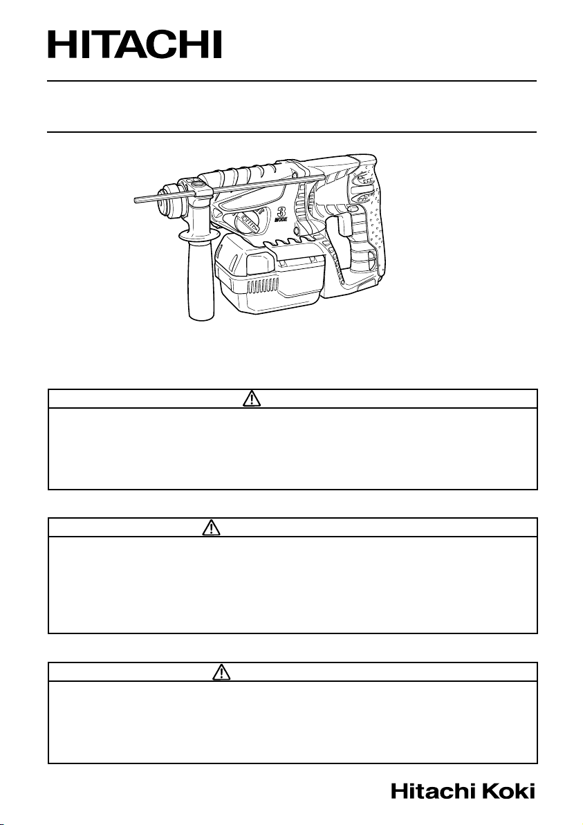
Model Cordless Rotary Hammer
Modèle Marteau rotatif sans fil
Modelo Martillo perforador a batería
DH 25DAL
SAFETY INSTRUCTIONS AND INSTRUCTION MANUAL
WARNING
IMPROPER OR UNSAFE use of this power tool can result in death or serious bodily
injury!
This manual contains important information about product safety. Please read
and understand this manual BEFORE operating the power tool. Please keep this
manual available for other users and owners before they use the power tool. This
manual should be stored in safe place.
INSTRUCTIONS DE SECURITE ET MODE D’EMPLOI
AVERTISSEMENT
Une utilisation INCORRECTE OU DANGEREUSE de cet outil motorisé peut entraîner
la mort ou de sérieuses blessures corporelles !
Ce mode d’emploi contient d’importantes informations à propos de la sécurité de
ce produit. Prière de lire et de comprendre ce mode d’emploi AVANT d’utiliser
l’outil motorisé. Garder ce mode d’emploi à la disponibilité des autres utilisateurs
et propriétaires avant qu’ils utilisent l’outil motorisé. Ce mode d’emploi doit être
conservé dans un endroit sûr.
INSTRUCCIONES DE SEGURIDAD Y MANUAL DE INSTRUCCIONES
ADVERTENCIA
¡La utilización INAPROPIADA O PELIGROSA de esta herramienta eléctrica puede
resultar en lesiones de gravedad o la muerte!
Este manual contiene información importante sobre la seguridad del producto.
Lea y comprenda este manual ANTES de utilizar la herramienta eléctrica. Guarde
este manual para que puedan leerlo otras personas antes de utilizar la herramienta
eléctrica. Este manual debe ser guardado en un lugar seguro.
Page 2
English
IMPORTANT SAFETY INFORMATION ................ 3
MEANINGS OF SIGNAL WORDS ........................ 3
SAFETY ...................................................................... 3
GENERAL SAFETY RULES ................................... 3
SPECIFIC SAFETY RULES AND SYMBOLS ......... 5
IMPORTANT SAFETY INSTRUCTIONS FOR
USE OF THE CORDLESS ROTARY
HAMMER ........................................................ 6
IMPORTANT SAFETY INSTRUCTIONS
FOR BATTERY CHARGER ............................. 6
IMPORTANT SAFETY INSTRUCTIONS
FOR USE OF THE BATTERY AND
BATTERY CHARGER ...................................... 7
CAUTION ON LITHIUM-ION BATTERY ............... 7
FUNCTIONAL DESCRIPTION .................................... 8
CONTENTS
Page
NAME OF PARTS .................................................. 8
SPECIFICATIONS ................................................ 10
ASSEMBLY AND OPERATION ............................... 11
APPLICATIONS ................................................... 11
REMOVAL AND INSTALLATION METHOD
OF BATTERY ................................................ 11
CHARGING METHOD ......................................... 11
BEFORE USE ....................................................... 13
PRIOR TO OPERATION ....................................... 13
HOW TO USE ...................................................... 15
MAINTENANCE AND INSPECTION ....................... 18
ACCESSORIES ......................................................... 19
STANDARD ACCESSORIES ............................... 19
OPTIONAL ACCESSORIES.....sold separately .....
PARTS LIST .............................................................. 64
Page
19
Français
INFORMATIONS IMPORTANTES DE SÉCURITÉ
SIGNIFICATION DES MOTS D’AVERTISSEMENT
SECURITE ................................................................ 23
REGLES GENERALE DE SÉCURITÉ ................... 23
REGLES DE SECURITE SPECIFIQUES ET SYMBOLES ......
CONSIGNES DE SÉCURITÉ IMPORTANTES
POUR L'UTILISATION DU MARTEAU
PERFORATEUR SANS FIL ........................... 26
CONSIGNES DE SÉCURITÉ IMPORTANTES
POUR LE CHARGEUR DE BATTERIE .......... 26
CONSIGNES DE SÉCURITÉ IMPORTANTES POUR L’UTILISATION
DE LA BATTERIE ET DU CHARGEUR DE BATTERIE ...
PRÉCAUTIONS RELATIVES A LA BATTERIE AU LITHIUM ION ...
DESCRIPTION FONCTIONNELLE ........................... 29
Español
INFORMACIÓN IMPORTANTE SOBRE SEGURIDAD ..
SIGNIFICADO DE LAS PALABRAS DE SEÑALIZACIÓN ...
SEGURIDAD ............................................................. 43
NORMAS GENERALES DE SEGURIDAD........... 43
NORMAS Y SÍMBOLOS ESPECÍFICOS DE SEGURIDAD
INSTRUCCIONES IMPORTANTES PARA
LA UTILIZACIÓN DEL MARTILLO
PERFORADOR A BATERÍA .......................... 46
INSTRUCCIONES IMPORTANTES DE SEGURIDAD
PARA EL CARGADOR DE BATERÍAS ......... 46
INSTRUCCIONES IMPORTANTES DE SEGURIDAD
PARA LA BATERÍA Y EL CARGADOR DE BATERÍAS ....
ADVERTENCIA DE LA BATERÍA DE LITIO ......... 48
DESCRIPCIÓN FUNCIONAL .................................... 49
TABLE DES MATIERES
Page
...... 23
.... 23
Página
... 45
ASSEMBLAGE ET FONCTIONNEMENT ................ 31
25
27
28
ENTRETIEN ET INSPECTION .................................. 38
ACCESSOIRES ......................................................... 39
LISTE DES PIECES ................................................... 64
ÍNDICE
43
43
MONTAJE Y OPERACIÓN ...................................... 51
47
MANTENIMIENTO E INSPECCIÓN ........................ 58
ACCESORIOS ........................................................... 59
LISTA DE PIEZAS .................................................... 64
NOM DES PARTIES ............................................ 29
SPECIFICATIONS ................................................ 30
UTILISATIONS .................................................... 31
MÉTHODE DE RETRAIT ET D’INSTALLATION
DE LA BATTERIE .......................................... 31
MÉTHODE DE RECHARGE ................................. 31
AVANT L’UTILISATION ...................................... 33
AANT LA MISE EN MARCHE ............................. 33
UTILISATION ....................................................... 35
ACCESSOIRES STANDARD ............................... 39
ACCESSOIRES EN OPTION.....vendus séparément .......
NOMENCLATURA ............................................... 49
ESPECIFICACIONES ............................................ 50
APLICACIONES ................................................... 51
MÉTODO DE EXTRACCIÓN E INSTALACIÓN
DE LA BATERÍA ............................................ 51
MÉTODO DE CARGA .......................................... 51
ANTES DE LA UTILIZACIÓN .............................. 53
ANTES DE LA OPERACIÓN ................................ 53
COMO SE USA .................................................... 55
ACCESORIOS ESTÁNDAR ................................. 59
ACCESORIOS OPCIONALES.....de venta por separado .....
Page
Página
39
59
Page 3
English
IMPORTANT SAFETY INFORMATION
Read and understand all of the safety precautions, warnings and operating instructions in the Instruction Manual
before operating or maintaining this power tool.
Most accidents that result from power tool operation and maintenance are caused by the failure to observe basic
safety rules or precautions. An accident can often be avoided by recognizing a potentially hazardous situation
before it occurs, and by observing appropriate safety procedures.
Basic safety precautions are outlined in the “SAFETY” section of this Instruction Manual and in the sections which
contain the operation and maintenance instructions.
Hazards that must be avoided to prevent bodily injury or machine damage are identified by WARNINGS on the
power tool and in this Instruction Manual.
NEVER use this power tool in a manner that has not been specifically recommended by HITACHI.
MEANINGS OF SIGNAL WORDS
WARNING indicates a potentially hazardous situations which, if ignored, could result in death or serious injury.
CAUTION indicates a potentially hazardous situations which, if not avoided, may result in minor or moderate
injury, or may cause machine damage.
NOTE emphasizes essential information.
SAFETY
GENERAL SAFETY RULES
WARNING:
Read all instructions
Failure to follow all instructions listed below may result in electric shock, fire and/or serious injury.
The term “power tool” in all of the warnings listed below refers to your mains-operated (corded) power tool
or battery-operated (cordless) power tool.
SAVE THESE INSTRUCTIONS
1) Work area safety
a) Keep work area clean and well lit.
Cluttered or dark areas invite accidents.
b) Do not operate power tools in explosive
atmospheres, such as in the presence of
flammable liquids, gases or dust.
Power tools create sparks which may ignite
the dust of fumes.
c) Keep children and bystanders away while
operating a power tool.
Distractions can cause you to lose control.
2) Electrical safety
a) Power tool plugs must match the outlet.
Never modify the plug in any way.
Do not use any adapter plugs with earthed
(grounded) power tools.
Unmodified plugs and matching outlets will
reduce risk of electric shock.
b) Avoid body contact with earthed or grounded
surfaces such as pipes, radiators, ranges and
refrigerators.
There is an increased risk of electric shock if
your body is earthed or grounded.
c) Do not expose power tools to rain or wet
conditions.
Water entering a power tool will increase the
risk of electric shock.
d) Do not abuse the cord. Never use the cord
for carrying, pulling or unplugging the power
tool.
Keep cord away from heat, oil, sharp edges
or moving parts.
Damaged or entangled cords increase the risk
of electric shock.
e) When operating a power tool outdoors, use
an extension cord suitable for outdoor use.
Use of a cord suitable for outdoor use reduces
the risk of electric shock.
3) Personal safety
a) Stay alert, watch what you are doing and use
common sense when operating a power tool.
Do not use a power tool while you are tired
or under the influence of drugs, alcohol or
medication.
A moment of inattention while operating
power tools may result in serious personal
injury.
3
Page 4

English
b) Use safety equipment. Always wear eye
protection.
Safety equipment such as dust mask, nonskid safety shoes, hard hat, or hearing
protection used for appropriate conditions
will reduce personal injuries.
c) Avoid accidental starting. Ensure the switch
is in the off position before plugging in.
Carrying power tools with your finger on the
switch or plugging in power tools that have
the switch on invites accidents.
d) Remove any adjusting key or wrench before
turning the power tool on.
A wrench or a key left attached to a rotating
part of the power tool may result in personal
injury.
e) Do not overreach. Keep proper footing and
balance at all times.
This enables better control of the power tool
in unexpected situations.
f) Dress properly. Do not wear loose clothing
or jewellery. Keep your hair, clothing and
gloves away from moving parts.
Loose clothes, jewellery or long hair can be
caught in moving parts.
g) If devices are provided for the connection of
dust extraction and collection facilities,
ensure these are connected and properly
used.
Use of these devices can reduce dust-related
hazards.
4) Power tool use and care
a) Do not force the power tool. Use the correct
power tool for your application.
The correct power tool will do the job better
and safer at the rate for which it was designed.
b) Do not use the power tool if the switch does
not turn it on and off.
Any power tool that cannot be controlled with
the switch is dangerous and must be repaired.
c) Disconnect the plug from the power source
and/or the battery pack from the power tool
before making any adjustments, changing
accessories, or storing power tools.
Such preventive safety measures reduce the
risk of starting the power tool accidentally.
d) Store idle power tools out of the reach of
children and do not allow persons unfamiliar
with the power tool or these instructions to
operate the power tool.
Power tools are dangerous in the hands of
untrained users.
e) Maintain power tools. Check for
misalignment or binding of moving parts,
breakage of parts and any other condition
that may affect the power tools operation.
If damaged, have the power tool repaired
before use.
Many accidents are caused by poorly
maintained power tools.
f) Keep cutting tools sharp and clean.
Properly maintained cutting tools with sharp
cutting edges are less likely to bind and are
easier to control.
g) Use the power tool, accessories and tool bits
etc., in accordance with these instructions
and in the manner intended for the particular
type of power tool, taking into account the
working conditions and the work to be
performed.
Use of the power tool for operations different
from intended could result in a hazardous
situation.
5) Battery tool use and care
a) Ensure the switch is in the off position before
inserting battery pack.
Inserting the battery pack into power tools
that have the switch on invites accidents.
b) Recharge only with the charger specified by
the manufacturer.
A charger that is suitable for one type of
battery pack may create a risk of fire when
used with another battery pack.
c) Use power tools only with specifically
designated battery packs.
Use of any other battery packs may create a
risk of injury and fire.
d) When battery pack is not in use, keep it away
from other metal objects like paper clips,
coins, keys, nails, screws, or other small
metal objects that can make a connection
from one terminal to another.
Shorting the battery terminals together may
cause burns or a fire.
e) Under abusive conditions, liquid may be
ejected from the battery, avoid contact. If
contact accidentally occurs, flush with water.
If liquid contacts eyes, additionally seek
medical help. Liquid ejected from the battery
may cause irritation or burns.
6) Service
a) Have your power tool serviced by a qualified
repair person using only identical
replacement parts.
This will ensure that the safety of the power
tool is maintained.
–WARNING–
To reduce the risk of injury, user must read
instruction manual.
4
Page 5
English
WARNING:
Some dust created by power sanding, sawing,
grinding, drilling, and other construction activities
contains chemicals known [to the State of California]
to cause cancer, birth defects or other reproductive
harm. Some examples of these chemicals are:
●
Lead from lead-based paints,
●
Crystalline silica from bricks and cement and other
masonry products, and
●
Arsenic and chromium from chemically-treated
lumber.
Your risk from these exposures varies, depending
on how often you do this type of work. To reduce
your exposure to these chemicals: work in a well
ventilated area, and work with approved safety
equipment, such as those dust masks that are
specially designed to filter out microscopic particles.
SPECIFIC SAFETY RULES AND SYMBOLS
1. Hold tools by insulated gripping surfaces when
performing an operation where the cutting tool
may contact hidden wiring.
Contact with a “live” wire will make exposed metal
parts of the tool “live” and shock the operator.
2. ALWAYS wear ear protectors when using the tool
3. NEVER touch moving parts.
NEVER place your hands, fingers or other body
parts near the tool’s moving parts.
4. NEVER operate without all guards in place.
NEVER operate this tool without all guards or
safety features in place and in proper working
order. If maintenance or servicing requires the
removal of a guard or safety feature, be sure to
replace the guard or safety feature before resuming
operation of the tool.
5. Use right tool.
Don’t force small tool or attachment to do the job
of a heavy-duty tool.
Don’t use tool for purpose not intended —for
example— don’t use circular saw for cutting tree
limbs or logs.
6. NEVER use a power tool for applications other
than those specified.
NEVER use a power tool for applications other than
those specified in the Instruction Manual.
7. Handle tool correctly.
Operate the tool according to the instructions
provided herein. Do not drop or throw the tool.
NEVER allow the tool to be operated by children,
individuals unfamiliar with its operation or
unauthorized personnel.
for extended periods.
Prolonged exposure to high intensity
noise can cause hearing loss.
8. Definitions for symbols used on this tool
V ............... volts
—
---
no ............ no load speed
---/min ...... revolutions or reciprocation per minute
9. Keep all screws, bolts and covers tightly in place.
Keep all screws, bolts, and plates tightly mounted.
Check their condition periodically.
10. Do not use power tools if the plastic housing or
handle is cracked.
Cracks in the tool’s housing or handle can lead to
electric shock. Such tools should not be used until
repaired.
11. Blades and accessories must be securely mounted
to the tool.
Prevent potential injuries to youself or others.
Blades, cutting implements and accessories which
have been mounted to the tool should be secure
and tight.
12. NEVER use a tool which is defective or operating
abnormally.
If the tool appears to be operating unusually,
making strange noises, or otherwise appears
defective, stop using it immediately and arrange
for repairs by a Hitachi authorized service center.
13. Carefully handle power tools.
Should a power tool be dropped or struck against
hard materials inadvertently, it may be deformed,
cracked, or damaged.
14. Do not wipe plastic parts with solvent.
Solvents such as gasoline, thinner benzine, carbon
tetrachloride, and alcohol may damage and crack
plastic parts. Do not wipe them with such solvents.
Wipe plastic parts with a soft cloth lightly
dampened with soapy water and dry thoroughly.
15. Keep motor air vent clean.
The tool’s motor air vent must be kept clean so
that air can freely flow at all times. Check for dust
build-up frequently.
16. ALWAYS wear eye protection that meets the
.............. direct current
requirement of the latest revision of
ANSI Standard Z87.1.
5
Page 6

English
IMPORTANT SAFETY INSTRUCTIONS FOR
USE OF THE CORDLESS ROTARY
HAMMER
WARNING:
Death or serious bodily injury could result from
improper or unsafe use of the cordless rotary
hammer. To avoid these risks, follow these basic
safety instructions:
1. NEVER touch the tool bit with bare hands after
operation.
2. NEVER wear gloves made of stuff liable to roll up
such as cotton, wool cloth or string, etc.
3. ALWAYS attach the side handle and securely grip
the Cordless Rotary Hammer.
4. ALWAYS be careful with buried object such as an
underground, wiring.
Touching these active wiring or electric cable with
this tool, you may receive an electric shock.
Comfirm if there are any buried object such as
electric cable within the wall, floor or ceiling where
you are going to operate here after.
IMPORTANT SAFETY INSTRUCTIONS FOR
BATTERY CHARGER
WARNING:
Death or serious bodily injury could result from
improper or unsafe use of battery chargers. To
avoid these risks, follow these basic safety
instructions:
READ ALL INSTRUCTIONS
1. This manual contains important safety and
operating instructions for battery charger Model
UC36YRL.
2. Before using battery charger, read all instructions
and cautionary markings on (1) battery charger,
(2) battery, and (3) product using battery.
3. To reduce risk of injury, charge HITACHI
rechargeable battery type BSL2530. Other type of
batteries may burst causing personal injury and
damage.
4. Do not expose battery charger to rain or snow.
5. Use of an attachment not recommended or sold
by the battery charger manufacturer may result in
a risk of fire, electric shock, or injury to persons.
6. To reduce risk of damage to electric plug and cord,
pull by plug when disconnecting battery charger.
7. Make sure cord is located so that it will not be
stepped on, tripped over, or otherwise subjected
to damage or stress.
8. An extension cord should not be used unless
absolutely necessary. Use of improper extension
cord could result in a risk of fire and electric shock.
If extension cord must be used make sure:
a. That blades of extension cord are the same
number, size, and shape as those of plug on
battery charger:
b. That extension cord is properly wired and in
good electrical condition; and
c. That wire size is large enough for AC ampere
rating of battery charger as specified in
Table 1.
Table 1
RECOMMENDED MINIMUM AWG SIZE FOR
EXTENSION CORDS FOR BATTERY CHARGERS
AC Input Rating Amperes* AWG Size of Cord
Equal to or but less Length of Cord, Feet (Meter)
greater than than 25 (7.5) 50 (15) 100 (30) 150 (45)
0 2 18 18 18 16
2 3 18 18 16 14
3 4 18 18 16 14
* If the input rating of a battery charger is given in
watts rather than in amperes, the corresponding
ampere rating is to be determined by dividing the
wattage rating by the voltage rating–for example:
1,250 watts
125 volts
= 10 amperes
9. Do not operate battery charger with damaged cord
or plug-replace them immediately.
10. Do not operate battery charger if it has received a
sharp blow, been dropped, or otherwise damaged
in any way; take it to a qualified serviceman.
6
11. Do not disassemble battery charger; take it to a
qualified serviceman when service or repair is
required. Incorrect reassembly may result in a risk
of electric shock or fire.
12. To reduce risk of electric shock, unplug charger
from receptacle before attempting any
maintenance or cleaning. Removing the battery
will not reduce this risk.
13. This battery charger might be attached to HITACHI
battery operated tools as a standard accessory. In
this case, please confirm Instruction Manual of the
HITACHI battery operated tools before using the
battery charger.
Page 7

English
IMPORTANT SAFETY INSTRUCTIONS FOR
USE OF THE BATTERY AND BATTERY
CHARGER
You must charge the battery before you can use the
power tool. Before using the model
UC36YRL battery charger, be sure to read all
instructions and cautionary statements on it, the battery
and in this manual.
REMEMBER: USE ONLY HITACHI BATTERY TYPE
BSL2530. OTHER TYPES OF BATTERIES MAY BURST
AND CAUSE INJURY!
Follow these instructions to avoid the risk of injury:
WARNING:
Improper use of the battery or battery charger can
lead to serious injury. To avoid these injuries:
1. NEVER disassemble the battery.
2. NEVER incinerate the battery, even if it is
damaged or is completely worn out. The battery
can explode in a fire.
3. NEVER short-circuit the battery.
4. NEVER insert any objects into the battery
charger’s air vents. Electric shock or damage to
the battery charger may result.
5. NEVER charge outdoors. Keep the battery away
from direct sunlight and use only where there is
low humidity and good ventilation.
6. NEVER charge when the temperature is below
32°F (0°C) or above 104°F (40°C).
7. NEVER connect two battery chargers together.
8. NEVER insert foreign objects into the hole for the
battery or the battery charger.
9. NEVER use a booster transformer when charging.
10. NEVER use an engine generator or DC power to
charge.
11. NEVER store the battery or battery charger in
places where the temperature may reach or exceed
104°F (40°C).
12.
ALWAYS
operate charger on standard household
electrical power (120 volts). Using the charger on
any other voltage may overheat and damage the
charger.
13.
ALWAYS
wait at least 15 minutes between charges
to avoid overheating the charger.
14.
ALWAYS
disconnect the power cord from its
receptacle when the charger is not in use.
CAUTION ON LITHIUM-ION BATTERY
To extend the lifetime, the lithium-ion battery equips
with the protection function to stop the output.
1. When the battery power remaining runs out (The
battery voltage drops to about 12V), the motor
stops.
In such case, charge it up immediately.
2. If the tool is overloaded, the motor may stop. In this
case, release the switch of tool and eliminate causes
of overloading. After that, you can use it again.
Furthermore, please heed the following warning and
caution.
WARNING:
In order to prevent any battery leakage, heat
generation, smoke emission, explosion and
ignition beforehand, please be sure to heed the
following precautions.
1. Make sure that swarf and dust do not collect on
the battery.
䡬 During work make sure that swarf and dust do
not fall on the battery.
䡬 Make sure that any swarf and dust falling on the
power tool during work do not collect on the
battery.
䡬 Do not store an unused battery in a location
exposed to swarf and dust.
䡬 Before storing a battery, remove any swarf and
dust that may adhere to it and do not store it
together with metal parts (screws, nails, etc.).
2. Do not pierce battery with a sharp object such
as a nail, strike with a hammer, step on, throw
or subject the battery to severe physical shock.
3. Do not use an apparently damaged or deformed
battery.
4. Do not use the battery in reverse polarity.
5. Do not connect directly to an electrical outlets or
car cigarette lighter sockets.
6. Do not use the battery for a purpose other than
those specified.
7. If the battery charging fails to complete even
when a specified recharging time has elapsed,
immediately stop further recharging.
8. Do not put or subject the battery to high
temperatures or high pressure such as into a
microwave oven, dryer, or high pressure container.
9. Keep away from fire immediately when leakage
or foul odor are detected.
10. Do not use in a location where strong static
electricity generates.
11. If there is battery leakage, foul odor, heat
generated, discolored or deformed, or in any way
appears abnormal during use, recharging or
storage, immediately remove it from the equipment
or battery charger, and stop use.
In the cases of 1 and 2 described below, when using
this product, even if you are pulling the switch, the
motor may stop. This is not the trouble but the result
of protection function.
7
Page 8
English
CAUTION:
1. If liquid leaking from the battery gets into your
eyes, do not rub your eyes and wash them well
with fresh clean water such as tap water and
contact a doctor immediately.
If left untreated, the liquid may cause eye-problems.
2. If liquid leaks onto your skin or clothes, wash well
with clean water such as tap water immediately.
There is a possibility that this can cause skin irritation.
3. If you find rust, foul odor, overheating, discolor,
deformation, and/or other irregularities when using
the battery for the first time, do not use and return
it to your supplier or vendor.
SAVE THESE INSTRUCTIONS
AND
MAKE THEM AVAILABLE TO OTHER USERS
AND
OWNERS OF THIS TOOL!
FUNCTIONAL DESCRIPTION
NOTE:
The information contained in this Instruction Manual is designed to assist you in the safe operation and
maintenance of the power tool.
NEVER operate, or attempt any maintenance on the tool unless you have first read and understood all safety
instructions contained in this manual.
Some illustrations in this Instruction Manual may show details or attachments that differ from those on your
own power tool.
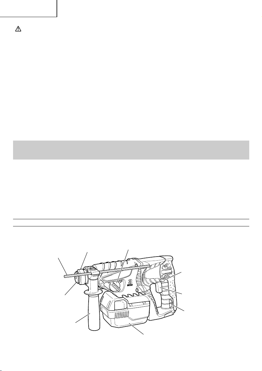
NAME OF PARTS
1. Cordless Rotary Hammer (DH25DAL)
Depth gauge
Front cap
Side handle
8
Grip
Change lever
Push button
Switch trigger
Shift knob
Battery
Page 9

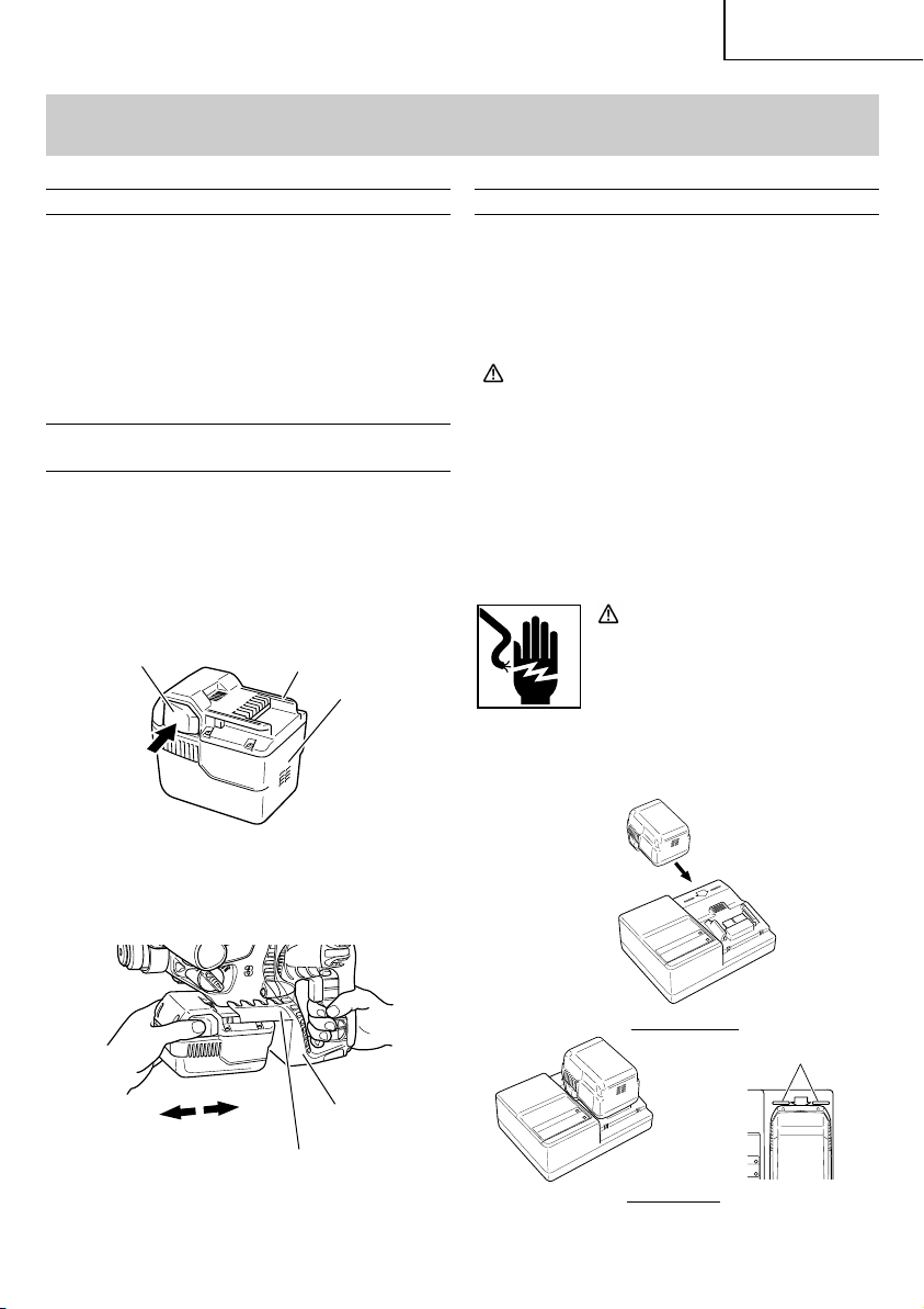
䡬
Battery (BSL2530)
Latch
Nameplate
2. Battery Charger (UC36YRL)
Charge status lamp (red)
English
Terminal hole
Fig. 1
Cooling fan
Overheat lamp (green)
Caution plate
Body
Rail for connecting the battery
Nameplate
Fig. 2
9
Page 10

English
SPECIFICATIONS
1. Cordless Rotary Hammer (DH25DAL)
Motor DC motor
No-load speed SAVE/POWER 0–550/min. / 0–1,000/min.
Full-load impact rate SAVE/POWER 0–2,250/min. / 0–4,500/min.
Concrete 1″ (26 mm)
Capacity Drilling Steel 1/2″ (13 mm)
Wood 1-3/16″ (30 mm) *
Battery (BSL2530)
Lithium - ion battery
Voltage ........ DC 25 V
Weight 7.9 lbs. (3.6 kg)
* Do not use the “SAVE” mode when boring holes with the wood drill. There is a likelihood that the motor will
burn out.
2. Battery Charger (UC36YRL)
Input power source Single phase: AC 120 V 60 Hz
Charging time
Approx. 60 min.
(At a temperature of 68°F (20°C))
Charging voltage DC 25.2–36 V
Charging current DC 3 A
Weight 2.0 lbs. (0.9 kg)
NOTE: The charging time may vary according to temperature and power source voltage.
10
Page 11
ASSEMBLY AND OPERATION
English
APPLICATIONS
Rotation and hammering function
䡬
Drilling anchor holes
䡬
Drilling holes in concrete
䡬
Drilling holes in tile
Rotatio n only function
䡬
Drilling in steel or wood
䡬
Tightening machine screws, wood screws
Hammering only function
䡬
Light-duty chiselling of concrete, groove digging
and edging.
REMOVAL AND INSTALLATION METHOD
OF BATTERY
1. Battery removal
Hold the handle tightly and push the battery latches
to remove the battery (See Figs. 3 and 4).
2. Battery installation
Insert the battery aligning both guide rail of battery
and body. Make sure the battery is fixed firmly.
(See Fig. 4)
Latch
Guide rail of battery
Battery
CHARGING METHOD
NOTE:
Before plugging into the receptacle, make sure the
following points.
䡬
The power source voltage is stated on the
nameplate.
䡬
The cord is not damaged.
WARNING:
Do not charge at voltage higher than indicated on
the nameplate.
If charged at voltage higher than indicated on the
nameplate, the charger will burn out.
1. Insert the plug of battery charger into the
receptacle.
When the plug of battery charger has been inserted
into the receptacle, the charge status lamp will
blink in red. (At 1-second intervals)
WARNING:
Do not use the electrical cord if
damaged. Have it repaired
immediately.
2. Insert the battery to the battery charger.
Insert the battery into the battery charger as shown
in Fig. 5. Make sure it contacts until the line is
visible.
Pull out
Fig. 3
Insert
Guide rail of housing
Fig. 4
Before insert
Line
Housing
After insert
Fig. 5
11
Page 12
English
3. Charging
䡬
When the battery is connected to the battery
charger, charging will commence and the charge
䡬
When the battery is fully charged, the charge status
lamp will bilink in red slowly. (At 1-second
intervals) (See Table 2)
status lamp will light in red. (See Table 2)
NOTE:
If the charge status lamp flikers in red, pull out the
plug from the receptacle and check if the battery
is properly mounted.
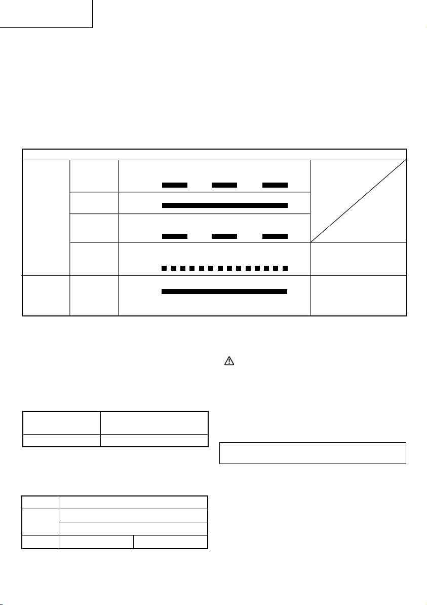
Table 2
Indications of the lamp
Charge
status
Before
charging
Blinks
(RED)
Lights for 0.5 seconds. Does not light for 0.5
seconds. (off for 0.5 seconds)
lamp (RED)
Lights continuously
Lights for 0.5 seconds. Does not light for 0.5
seconds. (off for 0.5 seconds)
Lights for 0.1 seconds. Does not light for 0.1
seconds. (off for 0.1 seconds)
Lights continuously
Malfunction in the
battery or the charger
Battery overheated.
Unable to charge
(Charging will commence
when battery cools).
Overheat
lamp
(GREEN)
While
charging
Charging
complete
Charging
impossible
Overheat
standby
Lights
(RED)
Blinks
(RED)
Flickers
(RED)
Lights
(GREEN)
NOTE: When standby for cooling battery, UC36YRL cools the overheated battery by cooling fan.
䡬
Regarding the temperature of the rechargeable
4. Disconnect battery charger from the receptacle.
battery.
The temperatures for rechargeable batteries are
as shown in the table below, and batteries that
have become hot should be cooled for a while
before being recharged.
Table 3
Rechargeable Temperatures at which the
batteries battery can be recharged
BSL2530 32°F — 122°F (0°C — 50°C)
䡬
Regarding recharging time
Table 4 shows the recharging time required
according to the type of battery.
Table 4 Recharging time (approx. min.) at 20°C
Battery capacity (Ah)
Battery
Voltage
Li-ion BATTERY
3.0 Ah
25.2V BSL2530 60min.
CAUTION:
Do not pull the plug out of the receptacle by pulling
on the cord.
Make sure to grasp the plug when removing from
receptacle to avoid damaging cord.
5. Remove the battery from the battery charger.
Supporting the battery charger with hand, pull out
the battery from the battery charger.
Regarding electric discharge in case of new
batteries, etc.
As the internal chemical substance of new batteries
and batteries that have not been used for an
extended period is not activated, the electric
discharge might be low when using them the first
and second time. This is a temporary
phenomenon, and normal time required for
recharging will be restored by recharging the
batteries 2 – 3 times.
NOTE:The recharging time may vary according to the
ambient temperature.
12
Page 13
English
How to make the batteries perform longer.
䡬
Recharge the batteries before they become
completely exhausted.
When you feel that the power of the tool becomes
weaker, stop using the tool and recharge its
battery. If you continue to use the tool and exhaust
the electric current, the battery may be damaged
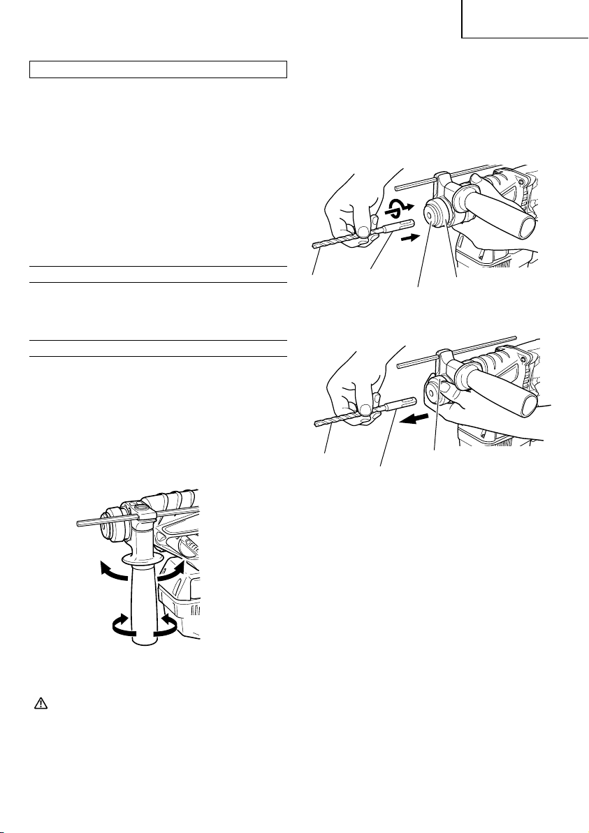
(1) Clean the shank portion of the drill bit.
(2) Insert the drill bit in a twisting manner into the tool
holder until it latches itself. (Fig. 7)
The grip need not be adjusted during bit installation.
(3) Check the latching by pulling on the drill bit.
(4) To remove the drill bit, fully pull the grip in the
direction of the arrow and pull out the drill bit. (Fig.
8)
and its life will become shorter.
䡬
Avoid recharging at high temperatures.
A rechargeable battery will be hot immediately
after use. If such a battery is recharged immediately
after use, its internal chemical substance will
deteriorate, and the battery life will be shortened.
Leave the battery and recharge it after it has cooled
for a while.
BEFORE USE
Check the work area to make sure that it is clear of debris
Drill bit
and clutter.
Clear the area of unnecessary personnel. Ensure that
lighting and ventilation is adequate.
PRIOR TO OPERATION
1. Confirming condition of the environment
Confirm that the work site is placed under
appropriate conditions conforming to prescribed
precautions.
2. Attaching the side handle (Fig. 6)
(1) Turn the grip of the side handle to loosen it and
push it in until it comes in contact with the housing.
(2) Adjust the side handle to the angle that allows the
easiest use, then turn the side handle’s grip firmly
Drill bit
to lock it place.
Part of
SDS-plus
shank
Front
cap
Fig. 7
Grip
Part of SDS-plus
shank
Fig. 8
Grip
Loosen
Tighten
Fig. 6
3. Mounting the drill bit (Fig. 7)
CAUTION:
To prevent accidents, make sure to turn the switch
off.
NOTE:
When using tools such as drill bits, etc., make sure
to use the genuine parts designated by our company.
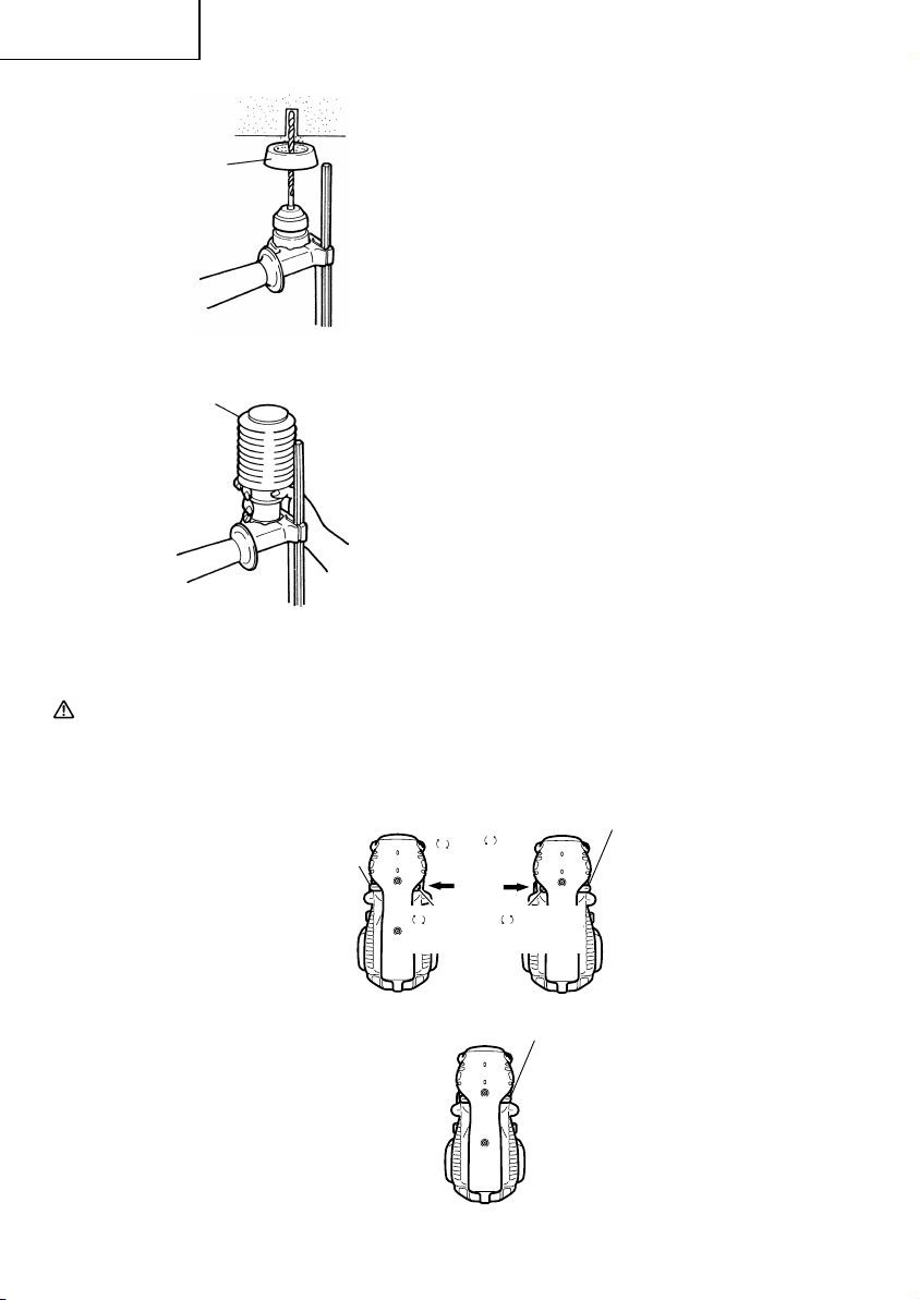
4. Installation of dust cup or dust collector (B)
(Optional accessories) (Fig. 9, Fig. 10)
When using a rotary hammer for upward drilling
operations attach a dust cup or a dust collector (B)
to collect dust or particles for easy operation.
䡬
Installing the dust cup
Use the dust cup by attaching to the drill bit as
shown in Fig. 9.
When using a bit which has big diameter, enlarge
the center hole of the dust cup with this rotary
hammer.
䡬
Installing dust collector (B)
When using dust collector (B), insert dust collector
(B) from the tip of the bit by aligning it to the groove
on the grip. (Fig. 10)
13
Page 14
English
Dust cup
Fig. 9
Dust
collector (B)
Fig. 10
CAUTION:
The dust cup and dust collector (B) are for
䡬
exclusive use of concrete drilling work. Do not use
them for wood or metal drilling work.
Push
the
Push
button
R
side
䡬
Insert dust collector (B) completely into the chuck
part of the main unit.
䡬
When turning the rotary hammer on while dust
collector (B) is detached from a concrete surface,
dust collector (B) will rotate together with the drill
bit. Make sure to turn on the switch after pressing
dust cup on the concrete surface. When using dust
collector (B) attached to a drill bit that has more
than 7-15/32" (190 mm) of overall length, dust
collector (B) cannot touch the concrete surface and
will rotate. Therefore, please use dust collector (B)
by attaching to drill bits which have 6-17/32" (166
mm), 6-19/64" (160 mm), and 4-21/64" (110 mm)
overall length.
䡬
Dump particles after every two or three holes
when drilling.
䡬
Please replace the drill bit after removing dust
collector (B).
5. Selecting the driver bit
Screw heads or bits will be damaged unless a bit
appropriate for the screw diameter is employed to
drive in the screws.
6. Confirm the direction of bit rotation (Fig. 11)
The bit rotates clockwise (viewed from the rear
side) by pushing the R-side of the push button. (Fig.
11-a)
The L-side of the push button is pushed to turn
the bit counterclockwise. (Fig. 11-b)
The motor does not rotate if the push button is set
to the center position. (Fig. 11-c)
Push
the
L
Push
button
side
R
indication
(a) Forward rotation
L
indication
(b) Reverse rotation
Push
button
Center
position
(c) Does not rotate
Fig. 11 Diagram seen from the handle side
14
Page 15

English
HOW TO USE
1. Switch operation
䡬
When the switch trigger is depressed, the tool
rotates. When the switch trigger is released, the
tool stops.
䡬
The rotational speed of the rotary hammer can be
controlled by varying the amount that the switch
trigger is pulled. Speed is low when the switch
trigger is pulled slightly and increases as the switch
trigger is pulled more.
䡬
When releasing the switch trigger, the brake will
be applied for immediate stopping.
3. Rotation only
Align the “ ” mark with the “ ” mark by rotating
the change lever to set the “Rotation only” mode.
(Fig. 12)
To drill a wood or metal material using the
separately sold drill chuck and chuck adaptor,
proceed as follows. Installing drill chuck and chuck
adaptor (Fig. 14):
(1) Attach the drill chuck to the chuck adaptor.
(2) The part of the SDS-plus shank is the same as the
drill bit. Therefore, refer to the item of “Mounting
the drill bit” for attaching it.
2. Rotation + Striking
Align the “ ” mark with the “ ” mark by
rotating the change lever to set the “Rotation +
Striking” mode. (Fig. 12)
“
”
mark
Drill chuck
Chuck adaptor
“ ”
mark
Change
lever
“
”
mark
”
“
mark
Fig. 12
(1) Mount the drill bit.
(2) Pull the trigger switch after applying the drill bit
tip to the drilling position. (Fig. 13)
CAUTION:
Application of force more than necessary will not
●
only reducing drilling efficiency at all, but will
deteriorate the tip edge of the drill bit and reduce
the service life of the rotary hammer in addition.
●
Drill bit may snap off while withdrawing the rotary
hammer from the drilled hole. For withdrawing,
it is important to use a pushing motion.
●
Do not attempt to drill anchor holes or holes in
concrete with the main unit in the rotation only
mode.
●
Do not attempt to use the rotary hammer in the
rotation and striking mode with the drill chuck and
chuck adaptor attached. This would seriously
shorten the service life of every components of
the machine.
Part of
SDS-plus
shank
Fig. 14
Grip
Front
cap
4. When driving machine screws (Fig. 15)
Fig. 13
(3) Pushing the rotary hammer forcibly is not
necessary at all. Pushing slightly so that drill dust
comes out gradually is just sufficient.
First, insert the bit into the socket in the end of
chuck adaptor (D).
Next, mount chuck adaptor (D) on the main unit
using procedures described in 3 (1), (2), (3), put
the tip of the bit in the slots in the head of the screw,
grasp the main unit and tighten the screw.
CAUTION:
When the drill bit touches an iron reinforcing rod,
●
the bit will stop immediately and the rotary
hammer will react to revolve. Therefore please grip
the side handle and handle tightly as shown in
Fig. 13.
15
Page 16
English
Bit
Socket
Chuck
adaptor (D)
Front cap
Grip
Fig. 15
CAUTION:
Exercise care not to excessively prolong driving
●
time, otherwise, the screws may be damaged by
excessive force.
●
Apply the rotary hammer perpendicularly to the
screw head when driving a screw; otherwise, the
screw head or bit will be damaged, or driving force
will not be fully transferred to the screw.
●
Do not attempt to use the rotary hammer in the
rotation and striking mode with chuck adaptor (D)
and bit attached.
5. Hammering only
Align the “ ” mark with the “ ” mark by
rotating the change lever to set the “Hammering
only” function. (Fig. 12)
(1) Mount the bull point or cold chisel.
6. When driving wood screws (Fig. 15)
(1) Selecting a suitable driver bit
Employ plus-head screws, if possible, since the
driver bit easily slips off the heads of slotted-head
screws.
(2) Tightening wood screws
䡬
Prior to tightening wood screws, make pilot holes
suitable for them in the wooden board. Apply the
bit to the screw head grooves and gently drive the
screws in the holes.
䡬
After rotating the rotary hammer at low speed for
a while until a wood screw in partly driven into
the wood, squeeze the trigger more strongly to
obtain the optimum driving force.
7. Using depth gauge (Fig. 16)
(1) Loosen the knob on the side handle, and insert the
depth gauge into the mounting hole on the side
handle.
(2) Adjust the depth gauge position according to the
depth of the hole and tighten the knob bolt securely.
Mounting hole
Depth gauge
Side handle
Fig. 16
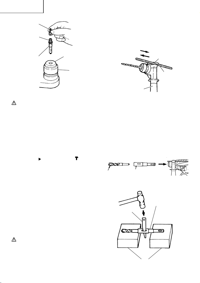
8. How to use the drill bit (taper shank) and the taper
shank adapter
(1) Mount the taper shank adapter to the rotary
hammer. (Fig. 17)
(2) Mount the drill bit (taper shank) to the taper shank
adapter. (Fig. 17)
(3) Turn the switch ON, and drill a hole to prescribed
depth.
(4) To remove the drill bit (taper shank), insert the
cotter into the slot of the taper shank adapter and
strike the head of the cotter with a hammer
supporting on the rest. (Fig. 18)
Drill bit
Taper shank
adapter
Fig. 17
Taper shank
adapter
Cotter
CAUTION:
Exercise care in preparing a pilot hole suitable for
the wood screw taking the hardness of the wood
into consideration. Should the hole be excessively
small or shallow, requiring much power to drive
the screw into it, the thread of the wood screw
may sometimes be damaged.
16
Rests
Fig. 18
Page 17
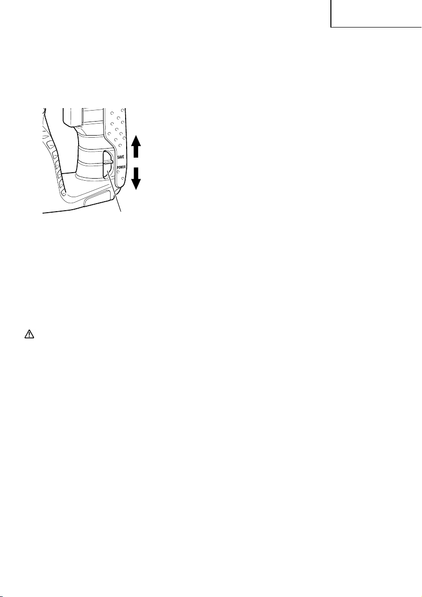
9. Switching between the “SAVE“ and the “POWER“
modes
The hammering force of the hammer can be
increased or decreased to conform with intended
usage, by operating the shift knob as per Fig. 19.
Adjust the force to match the usage intended.
“SAVE“ mode
“POWER“ mode
Shift knob
Fig. 19
(1) “SAVE“ mode ... decreased hammering force
This can prevent thin drill bits which are less than
5 mm in diameter, from being bent or broken.
(2) “POWER“ mode ... increased hammering force
䡬
This can be used to speedily and efficiently drill
holes when the drill bits which are being used are
greater than 5 mm in diameter.
䡬
This can be used to drill holes into wood or metal.
English
CAUTION:
Do not drill holes in wood with the “SAVE“ mode.
There is a likelihood that the motor will burn out
because it can easily lock up due to the low power.
17
Page 18
English
MAINTENANCE AND INSPECTION
CAUTION:
1. Inspecting the drill bits
Since use of a dull tool will cause motor
malfunctioning and degraded efficiency, replace
the drill bit with a new one or resharpening without
delay when abrasion is noted.
2. Check the Screws
Loose screws are dangerous. Regularly inspect
them and make sure they are tight.
CAUTION:
Using this power tool with loosened, screws is
extremely dangerous.
3. Maintenance of the motor
The motor unit winding is the very “heart” of the
power tool.
Exercise due care to ensure the winding does not
become damaged and/or wet with oil or water.
4. Inspecting the carbon brushes (Fig. 17)
For your continued safety and electrical shock
protection, carbon brush inspection and
replacement on this tool should ONLY be
performed by a HITACHI AUTHORIZED SERVICE
CENTER.
5. How to replace grease
Low viscosity grease is applied to this rotary
hammer so that it can be used for a long period
without replacing the grease. Please contact the
nearest service center for grease replacement
when any grease is leaking from loosened screw.
Further use of the rotary hammer despite the
grease shortage causes seizure to reduce the
service life.
CAUTION:
A specific grease is used with this machine,
therefore, the normal performance of the machine
may be badly affected by use of other grease.
Please be sure to let one of our service agents
undertake replacement of the grease.
Pull out battery before doing any inspection or maintenance.
7. Disposal of the exhausted battery
WARNING:
Do not dispose of the exhausted battery. The
battery must explode if it is incinerated. The
product that you have purchased contains a
rechargeable battery. The battery is recyclable. At
the end of it’s useful life, under various state and
local laws, it may be illegal to dispose of this
battery into the municipal waste stream. Check
with your local solid waste officials for details in
your area for recycling options or proper disposal.
8. Storage
Storing in a place below 104°F (40°C) and out of
the reach of children.
9. Service and repairs
All quality power tools will eventually require
servicing or replacement of parts because of wear
from normal use. To assure that only authorized
replacement parts will be used, all service and
repairs must be performed by a HITACHI
AUTHORIZED SERVICE CENTER, ONLY.
10. Service parts list
A: Item No.
B: Code No.
C: No. Used
D: Remarks
CAUTION:
Repair, modification and inspection of Hitachi
●
Power Tools must be carried out by a Hitachi
Authorized Service Center.
This Parts List will be helpful if presented with the
tool to the Hitachi Authorized Service Center when
requesting repair or other maintenance.
In the operation and maintenance of power tools,
the safety regulations and standards prescribed
in each country must be observed.
6. Check for Dust
Dust may be removed with a soft cloth or a cloth
dampened with soapy water.
Do not use bleach, chlorine, gasoline or thinner,
for they may damage the plastics.
18
MODIFICATIONS:
Hitachi Power Tools are constantly being improved
and modified to incorporate the latest
technological advancements.
Accordingly, some parts (i.e. code numbers and/
or design) may be changed without prior notice.
Page 19
English
ACCESSORIES
WARNING:
ALWAYS use Only authorized HITACHI replacement parts and accessories. NEVER use replacement parts or
accessories which are not intended for use with this tool. Contact HITACHI if you are not sure whether it is
safe to use a particular replacement part or accessory with your tool.
The use of any other attachment or accessory can be dangerous and could cause injury or mechanical
damage.
NOTE:
Accessories are subject to change without any obligation on the part of the HITACHI.
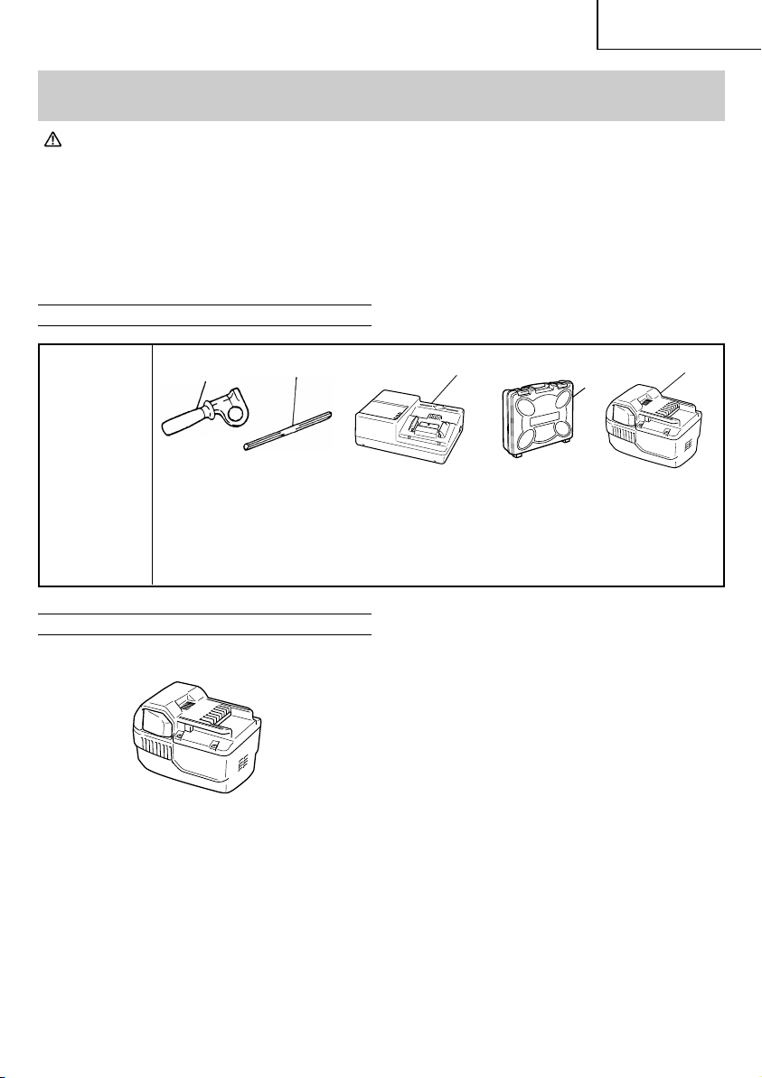
STANDARD ACCESSORIES
1
DH25DAL
1
(2SLCK)
OPTIONAL ACCESSORIES.....sold separately
1. Battery (BSL2530)
Side handle (Code No. 323155) ...............................................................................1
2
Depth gauge (Code No. 310331) ............................................................................. 1
3
Charger (UC36YRL) ..................................................................................................... 1
4
Plastic case (Code No. 323350) ................................................................................ 1
5
Extra battery (BSL2530) ............................................................................................. 1
2
3
5
4
19
Page 20
English
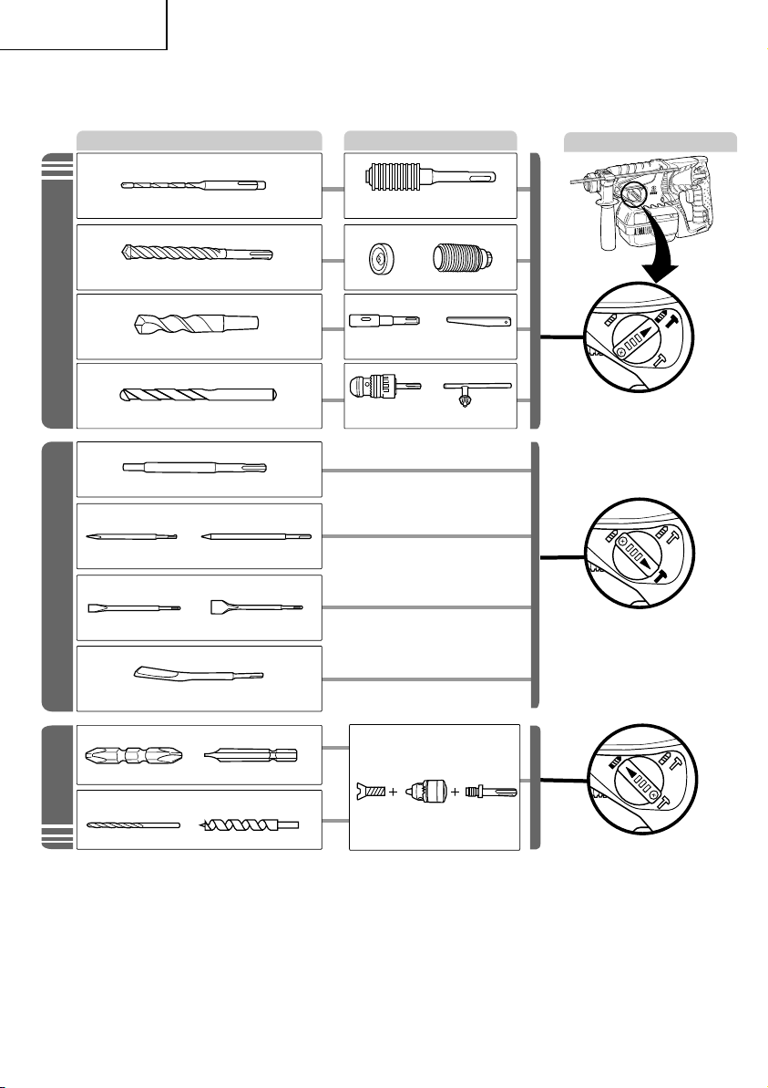
2. Tool and Adapter
Tool
䢇
Drilling holes in concrete or tile
Drill bit (Slender shaft)
䢇
Drilling holes in concrete or tile
Drill bit
䢇 Drilling anchor holes
Drill bit (Taper shank)
䢇
Drilling holes in concrete
Rotation + Hammering
Straight shank bit for
( )
impact drill
䢇Anchor setting
Anchor setting adapter
䢇 Demolishing operation
Bull point
(Square type)
䢇 Groove digging and edging
Cold chisel
Hammering only
䢇 Grooving
Bull point
(Round type)
Cutter
Adapters
Adapter for slender shaft
(SDS-plus shank)
Use on jobs facing upwards
Dust cup
Dust collector (B)
Taper shank
adapter
13 mm Rotary hammer chuck
(SDS-plus shank)
Cotter
+
Change lever position
䢇 Driving screws
, Driver bit - Driver bit
䢇 Drilling in steel or wood
Rotation only
Drill bit for steel Drill bit for wood
20
Grooving chisel
Special
screw
Drill chuck
(13 VLRB-D)
Chuck
adapter
Page 21

䢇
Drilling holes in concrete or tile
Drill Bit (Slender shaft)
English
Drill Bit (Slender Shaft)
Outer dia. Effective Length Overall Length Code No. Code No.
1/8" 1-25/32" 3-35/64"
(3.4 mm) (45 mm) (90 mm)
9/64" 1-25/32" 3-35/64"
(3.5 mm) (45 mm) (90 mm)
SDS-plus Drill bit
Outer dia. Overall length Effective length Code No.
5/32" (4.0 mm) 4-5/16" (110 mm) 2" (50 mm) 303571
3/16" (5.0 mm)
7/32" (5.5 mm) 4-5/16" (110 mm) 2" (50 mm) 303576
1/4" (6.5 mm) 6-5/16" (160 mm) 4" (100 mm) 303581
9/32" (7.0 mm) 6-5/16" (160 mm) 4" (100 mm) 303582
5/16" (8.0 mm) 6-5/16" (160 mm) 4" (100 mm) 303584
11/32" (8.5 mm) 6-5/16" (160 mm) 4" (100 mm) 303585
3/8" (9.0 mm) 6-5/16" (160 mm) 4" (100 mm) 303586
15/32" (12.0 mm)
1/2" (12.7 mm) 6-1/2" (166 mm) 4" (100 mm) 303593
9/16" (14.0 mm) 6-1/2" (166 mm) 4" (100 mm) 303595
19/32" (15.0 mm) 6-1/2" (166 mm) 4" (100 mm) 303598
5/8" (16.0 mm)
䢇
Drilling anchor holes
4-5/16" (110 mm) 2" (50 mm) 303575
6-5/16" (160 mm) 4" (100 mm) 303578
6-1/2" (166 mm) 4" (100 mm) 303591
10-1/4" (260 mm) 7-7/8" (200 mm) 303606
6-1/2" (166 mm) 4" (100 mm) 303599
10-1/4" (260 mm) 7-7/8" (200 mm) 303611
Drill Bit (Taper Shank) Taper Shank Adaptor
External dia. Code No.
7/16"
(11 mm)
1/2"
(12.3 mm)
1/2"
(12.7 mm)
9/16"
(14.3 mm)
9/16"
(14.5 mm)
11/16"
(17.5 mm)
7/8"
(21.5 mm)
944460
944461
993038
944462
944500
944463
944464
Taper mode Code No. Applicable drill bit
Morse taper
(No. 1)
Morse taper
(No. 2)
A-taper 303619
B-taper 303620
303617
303618 7/8" (21.5 mm)
Cotter: Code No. 944477
Adaptor for
Slender Shaft
306369
306368
306370
Code No.
Dust cup 971787
Dust collector (B) 306885
7/16" (11 mm)
Drill bit
(Taper
shank)
Drill bit
(Taper
shank)
Taper shank adaptor formed A-taper or
B-taper is provided as an optional accessory, but drill bit for it is not provided.
1/2" (12.3 mm)
1/2" (12.7 mm)
9/16" (14.3 mm)
9/16" (14.5 mm)
11/16" (17.5 mm)
21
Page 22

English
䢇
Drilling holes in concrete
Rotary hammer chuck
Capacity Code No.
2.5-13mm 303332
䢇
Anchor setting
Anchor setting adaptor (for Rotary hammer)
<Outer wedge type with the female screw>
Anchor size
Overall Length
Code No. 302976 302975 303621 302974
<Inner wedge type with the headless screw>
nchor size
A
Overall Length
Code No. 302979 302978 303622 302977
Anchor setting adaptor (for Manual hammer)
<Outer wedge type with
the female screw>
Anchor size Code No.
W1/4"
(6.3 mm)
W5/16"
(8 mm)
W3/8"
(9.5 mm)
W1/2"
(12.7 mm)
W5/8"
(15.9 mm)
W 1/4" W 5/16" W 3/8"
(6.3 mm) (8 mm) (9.5 mm)
10-1/4" 10-1/4" 6-1/4" 10-1/4"
(260 mm) (260 mm) (160 mm) (260 mm)
W 1/4" W 5/16" W 3/8"
(6.3 mm) (8 mm) (9.5 mm)
10-1/4" 10-1/4" 6-1/4" 10-1/4"
(260 mm) (260 mm) (160 mm) (260 mm)
<Inner wedge type with
the headless screw>
Anchor size Code No.
971794
971795
971796
971797
971798
W1/4"
(6.3 mm)
W5/16"
(8 mm)
W3/8"
(9.5 mm)
W1/2"
(12.7 mm)
W5/8"
(15.9 mm)
971799
971800
971801
971802
971803
䢇
Demolishing operation
Bull point
Type Overall length Code No.
Round
Square 316656
䢇
Grooving
Grooving chisel 316659
10" (250 mm)
Code No.
303046
䢇
Groove digging and edging
Code No.
Cold chisel 316657
Cutter 316658
䢇
Driving screws
Drilling in steel or wood
Special screw 981122
Drill chuck 321814
Chuck adaptor 303623
NOTE:
Specifications are subject to change without any obligation on the part of the HITACHI.
22
Page 23

Français
INFORMATIONS IMPORTANTES DE SÉCURITÉ
Lire et comprendre toutes les précautions de sécurité, les avertissements et les instructions de fonctionnement
dans ce mode d’emploi avant d’utiliser ou d’entretenir cet outil motorisé.
La plupart des accidents causés lors de l’utilisation ou de l’entretien de l’outil motorisé proviennent d’un non
respect des règles ou précautions de base de sécurité. Un accident peut la plupart du temps être évité si l’on
reconnaît une situation de danger potentiel avant qu’elle ne se produise, et en observant les procédures de sécurité
appropriées.
Les précautions de base de sécurité sont mises en évidence dans la section “SECURITE” de ce mode d’emploi et
dans les sections qui contiennent les instructions de fonctionnement et d’entretien.
Les dangers qui doivent être évités pour prévenir des blessures corporelles ou un endommagement de la machine
sont identifiés par AVERTISSEMENTS sur l’outil motorisé et dans ce mode d’emploi.
NE JAMAIS utiliser cet outil motorisé d’une manière qui n’est pas spécifiquement recommandée par HITACHI.
SIGNIFICATION DES MOTS D’AVERTISSEMENT
AVERTISSEMENT indique des situations potentiellement dangereuses qui, si elles sont ignorées, pourraient
entraîner la mort ou de sérieuses blessures.
PRECAUTION indique des situations dangereuses potentilles qui, si elles ne sont pas évitées, peuvent entraîner
de mineures et légères blessures ou endommager la machine.
REMARQUE met en relief des informations essentielles.
SECURITE
REGLES GENERALE DE SÉCURITÉ
AVERTISSEMENT :
Lire toutes les instructions
Tout manquement à observer ces instructions peut engendrer des chocs électriques, des incendies et/ou des
blessures graves.
Le terme “outil électrique” qui figure dans l'ensemble des avertissements ci-dessous se réfère aux outils
électriques (câblé) ou aux outils à piles (sans fil).
CONSERVER CES INSTRUCTIONS
1) Sécurité de l’aire de travail
a) Maintenir l'aire de travail propre et bien
éclairée.
Les endroits encombrés ou sombres sont
propices aux accidents.
b) Ne pas utiliser d'outils électriques en
présence de liquides, gaz ou poussière
inflammables, au risque de provoquer une
explosion.
Les outils électriques créent des étincelles
susceptibles d'enflammer la poussière.
c) Ne pas laisser les enfants et les visiteurs
s'approcher de vous lorsque vous utiliser un
outil électrique.
Les distractions peuvent faire perdre le
contrôle.
2) Sécurité électrique
a) Les prises de l'outil électrique doivent
correspondre à la prise secteur.
Ne jamais modifier la prise.
Ne pas utiliser d'adaptateurs avec les outils
électriques mis à la masse.
Les prises non modifiées et les prises secteurs
correspondantes réduisent les risques de
choc électrique.
b) Eviter tout contact avec les surfaces mises à
la masse telles que les tuyaux, radiateurs,
bandes et réfrigérateurs.
Le risque de choc électrique est accru en cas
de mise à la masse du corps.
c) Ne pas exposer les outils électriques à la pluie
ou à des conditions humides.
Si l'eau pénètre dans l'outil, cela augmente
les risques de choc électrique.
d) Ne pas utiliser le cordon à tort. Ne jamais
utiliser le cordon pour transporter ou
débrancher l'outil électrique.
Maintenir le cordon loin de la chaleur, de
l'huile, des bords pointus ou des pièces
mobiles.
Les cordons endommagés ou usés
augmentent les risques de choc électrique.
e) En cas d'utilisation d'un outil électrique à
l'extérieur, utiliser un cordon de rallonge
adapté à un usage extérieur.
23
Page 24

Français
L'utilisation d'un cordon adapté à l'usage
extérieur réduit les risques de choc électrique.
3) Sécurité personnelle
a) Restez alerte, regarder ce que vous faites et
usez de votre bon sens en utilisant un outil
électrique.
Ne pas utiliser d'outil électrique si vous êtes
sous l'influence de drogues, d'alcool ou de
médicaments.
Pendant l'utilisation d'outils électrique, un
instant d'inattention peut entraîner des
blessures graves.
b) Utiliser des équipements de sécurité.
Toujours porter des verres de protection.
L'utilisation d'équipements de sécurité tels
que les masques anti-poussière, les
chaussures de sécurité anti-dérapantes, les
casques ou les protections auditives dans des
conditions appropriées réduisent les risques
de blessures.
c) Eviter les démarrages accidentels. Veiller à
ce que l'interrupteur soit en position d'arrêt
avant de brancher l'outil.
Transporter les outils électriques avec le doigt
sur l'interrupteur ou brancher les outils
électriques avec l'interrupteur en position de
marche peut entraîner des accidents.
d) Retirer toute clé de sécurité ou clé avant de
mettre l'outil électrique en marche.
Laisser une clé ou une clé de sécurité sur une
partie mobile de l'outil électrique peut
engendrer des blessures.
e) Ne pas trop se pencher. Toujours garder une
bonne assise et un bon équilibre pendant le
travail.
Cela permet un meilleur contrôle de l'outil
électrique dans des situations imprévisibles.
f) Porter des vêtements adéquats. Ne pas
porter de vêtements amples ni de bijoux.
Maintenir les cheveux, les vêtements et les
gants loin des pièces mobiles.
Les vêtements amples ou les cheveux longs
peuvent se prendre dans les pièces mobiles.
g) En cas de dispositifs destinés au
raccordement d'installations d'extraction et
de recueil de la poussière, veiller à ce qu'ils
soient correctement raccordés et utilisés.
L'utilisation de ces dispositifs peut réduire les
dangers associés à la poussière.
4) Utilisation et entretien d'un outil électrique
a) Ne pas forcer sur l'outil électrique. Utiliser
l'outil électrique adapté à vos travaux.
Le bon outil électrique fera le travail mieux
et en toute sécurité au régime pour lequel il a
été conçu.
b) Ne pas utiliser l'outil électrique si
l'interrupteur ne le met pas en position de
marche et d'arrêt.
24
Tout outil ne pouvant être contrôlé par
l'interrupteur est dangereux et doit être
réparé.
c) Débrancher la prise ou retirer la batterie
avant de procéder à des réglages, au
remplacement des accessoires ou au
stockage des outils électriques.
Ces mesures préventives de sécurité
réduisent les risques de démarrage accidentel
de l'outil électrique.
d) Stockez les outils électriques inutilisés hors
de la portée des enfants et ne pas laisser des
personnes non familiarisées avec l'outil ou
ces instructions utiliser l'outil électrique.
Les outils électriques sont dangereux entre
les mains d'utilisateurs non habilités.
e) Entretenir les outils électriques. Vérifier
l'absence de mauvais alignement ou d'arrêt,
d'endommagement de pièces ou toute autre
condition susceptible d'affecter l'opération de
l'outil.
Si l'outil est endommagé, le faire réparer
avant utilisation.
De nombreux accidents sont dus à des outils
mal entretenus.
f) Maintenir les outils coupants aiguisés et
propres.
Des outils coupants bien entretenus avec des
bords aiguisés sont moins susceptibles de se
coincer et plus simples à contrôler.
g) Utiliser l'outil électrique, les accessoires et
les mèches de l'outil, etc. conformément à
ces instructions et de la manière destinée
pour le type précis d'outil électrique, en
tenant compte des conditions d'utilisation et
du travail à réaliser.
L'utilisation de l'outil électrique pour des
opérations différentes de celles pour
lesquelles il a été conçu est dangereuse.
5) Utilisation et entretien de la batterie
a) Veiller à mettre l’interrupteur en position off
avant d’insérer la batterie.
L’insertion de la batterie dans des outils
électriques avec l’interrupteur allumé est
propice aux accidents.
b) Recharger la batterie uniquement avec le
chargeur recommandé par le fabricant.
Un chargeur inadéquat pour le type de
batterie peut entraîner un risque d’incendie
en cas d’utilisation avec une autre batterie.
c) Utiliser les outils électriques uniquement
avec les batteries spécifiées.
L’utilisation d’autres batteries peut entraîner
un risque de blessures et d’incendie.
d) Lorsque la batterie est inutilisée, la garder à
l’écart d’objets métalliques comme des
trombones, des pièces de monnaie, des clés,
des clous, des vis ou autres petits objets
métalliques pouvant raccorder les bornes.
Page 25

Français
La connexion des bornes peut entraîner des
2. TOUJOURS porter des protecteurs d’oreille lors
blessures ou un incendie.
e) En cas d’utilisation dans des conditions
extrêmes, du liquide peut être émis de la
batterie. Éviter tout contact. en cas de
contact accidentel, rincer à l’eau. Si le liquide
entre en contact avec les yeux, consulter un
médecin.
Le liquide émis par la batterie peut entraîner
des irritations et des brûlures.
6) Service
a) Faire entretenir l'outil électrique par un
technicien habilité à l'aide de pièces de
rechange identiques exclusivement.
Cela garantira le maintien de la sécurité de
l'outil électrique.
3. NE JAMAIS toucher les parties mobiles.
NE JAMAIS placer ses mains, ses doigts ou toute
autre partie de son corps près des parties mobiles
de l’outil.
4. NE JAMAIS utiliser l’outil sans que tous les
dispositifs de sécurité ne soient en place.
NE JAMAIS faire fonctionner cet outil sans que
tous les dispositifs et caractéristiques de sécurité
ne soient en place et en état de fonctionnement.
Si un entretien ou une réparation nécessite le
–PRECAUTION–
Pour réduire tout risque de blessure, l’utilisateur
doit lire le mode d’emploi.
AVERTISSEMENT:
La poussière résultant d'un ponçage, d'un sciage,
d'un meulage, d'un perçage ou de toute autre
activité de construction renferme des produits
chimiques qui sont connus par l'Etat de Californie
pour causer des cancers, des défauts de naissance
et autres anomalies de reproduction. Nous
énumérons ci-dessus certains de ces produits
chimiques:
●
Plomb des peintres à base de plomb,
●
Silice cristalline des briques et du ciment et autres
matériaux de maçonnerie, et
●
Arsenic et chrome du bois d'oeuvre traité
chimiquement.
Le risque d'exposition à ces substances varie en
fonction de la fréquence d'exécution de ce genre de
travail. Pour réduire l'exposition à ces produits
chimiques, travailler dans un lieu bien ventilé, et
porter un équipement de protection agréé, par
exemple un masque anti-poussière spécialement
conçu pour filter les particules microscopiques.
retrait d’un dispositif ou d’une caractéristique de
sécurité, s’assurer de bien remettre en place le
dispositif ou la caractéristique de sécurité avant
de recommencer à utiliser l’outil.
5. Utiliser l’outil correct
Ne pas forcer sur un petit outil ou accessoire pour
faire le travail d’un outil de grande puissance. Ne
pas utiliser un outil pour un usage pour lequel il
n’a pas été prévu: par exemple, ne pas utiliser une
scie circulaire pour couper des branches d’arbre
ou des bûches.
6. NE JAMAIS utiliser un outil motorisé pour des
applications autres que celles spécifiées.
NE JAMAIS utiliser un outil motorisé pour des
applications autres que celles spécifiées dans le
mode d’emploi.
7. Manipuler l’outil correctement
Utiliser l’outil de la façon indiquée dans ce mode
d’emploi. Ne pas laisser tomber ou lancer l’outil.
NE JAMAIS permettre que l’outil soit utilisé par
des enfants, des personnes non familiarisées avec
son fonctionnement ou un personnel non autorisé.
8. Définitions pour les symboles utilisés sur cet outil
V ..................... volts
—
---
no ................... vitesse sans charge
---/min ............ rotations ou mouvements de va-et-
REGLES DE SECURITE SPECIFIQUES ET
SYMBOLES
1. Tenir les outils par les surfaces de grippage lors
de la réalisation d’opérations où l’outil de coupe
risque d’entrer en contact avec des câbles cachés.
Un contact avec un fil “sous tension” mettra les
parties métalliques de l’outil “sous tension” et
électrocutera l’utilisateur.
9. Maintenir toutes les vis, tous les boulons et les
couvercles fermement en place.
Maintenir toutes les vis, tous les boulons et les
couvercles fermement montés. Vérifier leurs
conditions périodiquement.
10. Ne pas utiliser les outils motorisés si le revêtement
de plastique ou la poignée est fendu.
Des fentes dans le revêtement ou la poignée
peuvent entraîner une électrocution. De tels outils
ne doivent pas être utilisés avant d’être réparé.
de l’utilisation de l’outil pendant de
longues périodes.
Une exposition prolongée à un son de
forte intensité peut endommager l’ouïe
de l’utilisateur.
.................... courant continu
vient par minute
25
Page 26

Français
11. Les lames et les accessoires doivent être
fermement montés sur l’outil.
Eviter les blessures potentielles personnelles et
aux autres. Les lames, les instruments de coupe
et les accessoires qui ont été montés sur l’outil
doivent être fixés et serrés fermement.
12. NE JAMAIS utiliser un outil défectueux ou qui
fonctionne anormalement.
Si l’outil n’a pas l’air de fonctionner normalement,
fait des bruits étranges ou sans cela paraît
défectueux, arrêter de l’utiliser immédiatement et
le faire réparer par un centre de service Hitachi
autorisé.
13. Manipuler l’outil motorisé avec précaution.
Si un outil motorisé tombe ou frappe un matériau
dur accidentellement, il risque d’être déformé,
fendu ou endommagé.
14. Ne pas essuyer les parties en plastique avec du
solvant.
Les solvants comme l’essence, les diluants, la
benzine, le tétrachlorure de carbone et l’alcool
peuvent endommager et fissurer les parties en
plastique. Ne pas les essuyer avec de tels solvants.
Essuyer les parties en plastique avec un chiffon
doux légèrement imbibé d’une solution d’eau
savonneuse et sécher minutieusement.
15. Garder propres les évents d’air du moteur
Les évents d’air du moteur doivent être maintenus
propres de façon que l’air puisse circuler librement
tout le temps. Vérifier les accumulations de
poussière fréquemment.
16. TOUJOURS porter des lunettes des protections
conformes aux exigences des
dernières révisions du standard ANSI
Z87.1.
4. TOUJOURS faire attention aux objets dissimulés,
par exemple des fils électriques sans fil.
Le fait de toucher un câblage ou un fil électrique
avec l’outil risque de provoquer un choc électrique.
Vérifier qu’il n’y a pas d’objets, par exemple des
fils électriques, dissimulés dans le mur, le plancher
ou le plafond sur lesquels on doit travailler.
CONSIGNES DE SÉCURITÉ IMPORTANTES
POUR LE CHARGEUR DE BATTERIE
AVERTISSEMENT:
Une utilisation incorrecte ou dangereuse des
chargeurs de batterie peut entraîner la mort ou
des blessures graves.
LIRE TOUT CE MODE D'EMPLOI
1. Ce manuel renferme des consignes de sécurité et
d’utilisation importantes pour le chargeur de
batterie modèle UC36YRL.
2. Avant d’utiliser le chargeur de batterie, lire toutes
les étiquettes d’instruction et de précaution
apposées sur (1) le chargeur de batterie, (2) la
batterie, et (3) le produit utilisant la batterie.
3. Pour réduire tout risque de blessure, NE recharger
QUE les batteries rechargeables HITACHI utilisées
dans le modèle BSL2530. Les autres types de
batterie pourraient exploser et provoquer des
blessures ou des dommages.
4. Ne pas exposer le chargeur à la pluie ni à la neige.
5. L’utilisation d’un accessoire non recommandé ou
non vendu par le fabricant du chargeur de batterie
risque de provoquer un feu, une décharge
électrique ou des blessures.
6. Pour réduire tout risque de dommage de la fiche
et du cordon électrique, débrancher le cordon du
chargeur en tirant sur la fiche.
7. Vérifier que le cordon est placé de façon que
CONSIGNES DE SÉCURITÉ IMPORTANTES
POUR L’UTILISATION DU MARTEAU
ROTATIF SANS FIL
AVERTISSEMENT :
Une utilisation incorrecte ou sans sécurité du
marteau rotatif sans fil risque d’entraîner la mort
ou des blessures graves. Pour éviter ces risques,
observer les consignes de sécurité élémentaires
personne ne puisse marcher dessus, se prendre
les pieds dedans, ni l’endommager ou le soumettre
à des contraintes.
8. Ne pas utiliser de cordon de rallonge si cela n’est
pas absolument nécessaire. L’utilisation d’un
cordon de rallonge incorrect pourrait entraîner un
feu ou une décharge électrique. Si l’on doit utiliser
un cordon de rallonge, s’assurer que:
a. Les broches de la rallonge ont les mêmes
suivantes :
1. NE JAMAIS toucher la mèche avec des mains nues
tout de suite après l’utilisation.
2. NE JAMAIS porter de gants faits de matériaux
b. Le cordon de rallonge est correctement
c. Le calibre du fil doit être au moins suffisant
susceptibles de s’a’effilocher, comme du coton, de
la laine, de la toile ou de la ficelle, etc.
3. TOUJOURS fixer la poignée latérale et tenir
fermement le marteau rotatif sans fil.
numéro, taille et forme que celles de la fiche
du chargeur ;
raccordé et en bon état électrique ;
pour l’intensité nominale CA (ampères) du
chargeur de batterie spécifiées dans le
tableau ci-dessous.
26
Page 27

Tableau 1
CALIBRE MINIMUM RECOMMANDÉ POUR LES CORDONS DE RALLONGE
DES CHARGEURS DE BATTERIE
Intensité nominale d’entrée CA (ampères)* Calibre du cordon
Egal ou mais non Longueur de cordon en pieds (mètres)
supérieur à inférieur à 25 (7.5) 50 (15) 100 (30) 150 (45)
0 2 18 18 18 16
2 3 18 18 16 14
3 4 18 18 16 14
Français
* Si l’intensité nominale d’entrée du chargeur de
batterie est donnée en watts et non en ampères,
calculer la capacité en ampères correspondante en
divisant la capacité en ampères par la capacité de
tension, par exemple:
1,250 watts
125 volts
= 10 ampères
9. Ne pas utiliser le chargeur si son cordon ou sa fiche
sont endommagés - Le remplacer immédiatement.
10. Ne pas utiliser le chargeur s’il a reçu un coup, s’il
est tombé ou endommagé de toute autre manière.
L’apporter à un réparateur qualifié.
11. Ne pas démonter le chargeur ni le produit qui reçoit
la batterie ; si un entretien ou des réparations sont
nécessaires, les apporter à un réparateur qualifié.
Un remontage incorrect pourrait provoquer une
décharge électrique ou un feu.
12. Pour réduire tout risque de décharge électrique,
débrancher le chargeur de la prise secteur avant
tout entretien ou nettoyage. Il ne suffit pas de sortir
la batterie.
13. Ce chargeur de batterie pourra être fixé comme
accessoire standard sur les outils HITACHI
alimentés sur batterie. Dans ce cas, vérifier le mode
d’emploi de l’outil HITACHI alimenté sur batterie
avant d’utiliser le chargeur de batterie.
CONSIGNES DE SÉCURITÉ IMPORTANTES
POUR L’UTILISATION DE LA BATTERIE ET DU
CHARGEUR DE BATTERIE
Pour pouvoir utiliser la scie circulaire à batterie, il faudra
recharger la batterie. Avant d’utiliser le chargeur de
batterie modèle UC36YRL., bien lire attentivement
toutes les consignes et les avertissements signalés sur
le chargeur, sur la batterie ou dans ce manuel.
BIEN NOTER: UTILISER EXCLUSIVEMENT LE BATTERIE
HITACHI DE SÉRIE BSL2530. LES AUTRES TYPES DE
BATTERIE POURRAIENT EXPLOSER OU PROVOQUER
DES BLESSURES.
Pour éviter tout risque de blessure, observer les
AVERTISSEMENT:
Une utilisation incorrecte de la batterie ou du
chargeur de batterie risque de provoquer des
blessures. Pour éviter tout risque de blessure:
1. NE JAMAIS démonter la batterie.
2. NE JAMAIS jeter la batterie au feu, même si elle
est endommagée ou complètement usée. La
batterie risque d’exploser au feu.
3. NE JAMAIS court-circuiter la batterie.
4. NE JAMAIS insérer d’objets dans les ouïes
d’aération du chargeur. Il pourrait en résulter un
choc électrique ou des dommages du chargeur.
5. NE JAMAIS effectuer la recharge à l’extérieur.
Eloigner la batterie des rayons directs du soleil et
utiliser exclusivement dans des endroits à faible
humidité et bien aérés.
6. NE JAMAIS effectuer la recharge si la température
est inférieure à 32°F (0°C) ou supérieure à 104°F
(40°C).
7. NE JAMAIS raccorder deux chargeurs de batterie
ensemble.
8. NE JAMAIS insérer de corps étrangers dans
l’orifice de la batterie ou du chargeur de batterie.
9. NE JAMAIS utiliser de transformateur-élévateur
pour la recharge.
10. NE JAMAIS utiliser de générateur de moteur ni
d’alimentation CC pour la recharge.
11. NE JAMAIS ranger la batterie ni le chargeur de
batterie dans un lieu où la température peut
atteindre ou dépasser 104°F (40°C).
12. TOUJOURS alimenter le chargeur sur une prise
secteur domestique standard (120 volts).
L’utilisation du chargeur à une autre tension peut
entraîner une surchauffe et endommager le
chargeur.
13. TOUJOURS attendre au moins 15 minutes entre
deux recharges pour éviter toute surchauffe du
chargeur.
14. TOUJOURS débrancher le cordon d’alimentation
de la prise secteur lorsqu’on ne se sert pas du
chargeur.
consignes suivantes:
27
Page 28

Français
PRÉCAUTIONS RELATIVES A LA BATTERIE
AU LITHIUM ION
Pour prolonger sa durée de vie, la batterie lithium-ion
est équipée d'une fonction de protection qui coupe
automatiquement l'alimentation.
Dans les cas 1 et 2 décrits ci-dessous, il est possible que
le moteur s'arrête lorsque vous utilisez ce produit, même
si vous actionnez le commutateur. Il ne s'agit pas d'un
dysfonctionnement, mais du fonctionnement normal de
la protection.
1. Lorsque la charge restante de la batterie diminue
(la tension de la batterie chute d'environ 12 V), le
moteur s'arrête.
Dans ce cas de figure, chargez immédiatement la
batterie.
2. En cas de surcharge de l'outil, actionnez le
commutateur de l'outil et éliminez les causes de la
surcharge. Vous pouvez ensuite recommencer à
utiliser l'outil.
En outre, respectez la précaution et l’avertissement suivants.
AVERTISSEMENT:
Afin d’éviter toute fuite de la batterie, génération
de chaleur, émission de fumée, explosion et
inflammation, respectez scrupuleusement les
précautions suivantes :
1. Assurez-vous que les copeaux et la poussière ne
s’accumulent pas sur la batterie.
Lorsque vous travaillez, assurez-vous que les
copeaux et la poussière ne tombent pas sur la
batterie.
Assurez-vous que les copeaux et la poussière qui
tombent sur l’outil lorsque vous travaillez ne
s’accumulent pas sur la batterie.
Ne conservez pas une batterie inutilisée dans un
endroit qui est exposé aux copeaux et à la
poussière.
Avant de stocker une batterie, retirez tous les
copeaux et la poussière qui ont pu y adhérer et ne
la conservez pas avec des pièces métalliques (vis,
clous, etc.).
2. Ne percez pas la batterie à l’aide d’un objet pointu
tel qu’un clou. Ne la frappez pas à l’aide d’un
marteau. Ne marchez pas dessus, ne la lancez pas
et ne la soumettez pas un à choc physique
important.
3. N’utilisez pas une batterie dont l’extérieur est
déformé ou laisse penser qu’elle est défectueuse.
4. N’insérez pas la batterie à l’envers (pôles inversés).
5. Ne raccordez pas directement la batterie à une
prise électrique ou à un allume-cigare.
6. N’utilisez pas la batterie à d’autres fins que celle
spécifiée.
7. En cas d’échec du chargement d’une batterie,
même après un certain délai, arrêtez
immédiatement le rechargement.
8. N’exposez pas la batterie à des températures ou
à une pression élevées (four à micro-ondes,
séchoir, conteneur sous haute pression).
9. Maintenez à la batterie à l’écart de toute flamme
en cas de détection d’une fuite ou d’une mauvaise
odeur.
10. Ne pas utiliser à proximité d’une source puissante
d’électricité statique.
11. En cas de fuite de la batterie, de mauvaise odeur,
de génération de chaleur, de décoloration, de
déformation ou d’anomalie en cours d’utilisation,
de rechargement ou d’entreposage, ôtez
immédiatement la batterie de l’équipement ou du
chargeur de batterie et ne l’utilisez plus.
PRECAUTION:
1. En cas de projection dans les yeux de liquide
ayant fuit de la batterie, ne vous frottez pas les
yeux, rincez-les à l’eau claire et contactez
immédiatement un médecin.
En l’absence de traitement, le liquide peut
détériorer l’oeil.
2. En cas de projection de liquide ayant fuit de la batterie
sur votre peau ou vos vêtements, rincez
immédiatement ces derniers à l ’eau claire (au robinet).
Le liquide peut provoquer une irritation de la peau.
3. En cas de détection de rouille, de mauvaise odeur,
de surchauffe, de décoloration, de déformation et/
ou autres anomalies lors de la première utilisation
de la batterie, n’utilisez pas cette dernière et
renvoyez-la au fournisseur ou au fabricant.
CONSERVER CES INSTRUCTIONS
ET
LES METTRE A LA DISPOSITION DES AUTRES UTILISATEURS
ET
28
PROPRIETAIRES DE CET OUTIL!
Page 29

Français
DESCRIPTION FONCTIONNELLE
REMARQUE:
Les informations contenues dans ce mode d’emploi sont conçues pour assister l’utilisateur dans une utilisation
sans danger et un entretien de l’outil motorisé.
NE JAMAIS utiliser ni entreprendre une révision de l’outil sans avoir d’abord lu et compris toutes les
instructions de sécurité contenues dans ce manuel.
Certaines illustrations dans ce mode d’emploi peuvent montrer des détails ou des accessoires différents de
ceux de l’outil motorisé utilisé.
NOM DES PARTIES
1. Marteau rotatif sans fil (DH25DAL)
Jauge de
profondeur
Capuchon
avant
Poignée laterale
Batterie (BSL2530)
Attache
coulissante
Bouton de
changement
Taquet
Poussoir
Déclencheur
Bouton de
changement
Batterie
Orifice de prise
Plaque signalétique
Fig. 1
29
Page 30

Français
2. Chargeur de batterie (UC36YRL)
Voyant d’état de charge (rouge)
Voyant de surchauffe (vert)
Plaque de
précaution
Corps
SPECIFICATIONS
1. Marteau rotatif sans fil (DH25DAL)
Moteur Moteur CC
Vitesse à vide SAVE/POWER
Vitesse de percussion à pleine
charge
SAVE/POWER
0–550 tr/mn / 0–1,000 tr/mn
0–2,250 tr/mn / 0–4,500 tr/mn
Béton 1″ (26 mm)
Ventilateur de
refroidissement
Rail de connexion de la batterie
Plaque signalétique
Fig. 2
Capacité Perçage Acier 1/2″ (13 mm)
Bois 1-3/16″ (30 mm)*
Batterie (BSL2530)
Batterie ion-lithium
Tension ................ CC 25 V
Poids 7.9 lbs. (3.6 kg)
* Ne pas utiliser le mode “SAVE” pour percer des trous avec le foret à bois. Le moteur risque de brûler.
2. Chargeur de batterie (UC36YRL)
Source d’alimentation d’entrée Monophasée : CA 120 V 60 Hz
Durée de recharge
(à une température de 68°F (20°C))
Environ 60 mn
Tension de charge CC 25.2–36 V
Courant de charge CC 3A
Poids 2.0 lbs. (0.9 kg)
REMARQUE : La durée de recharge peut varier en fonction de la température et de la tension de la source
30
d’alimentation.
Page 31

ASSEMBLAGE ET FONCTIONNEMENT
Français
UTILISATIONS
Par action combinée de rotation et de percussion
Perçage de trous d’ancrage
Perçage de trous dans béton
Perçage de trous dans une tuile
Par action de rotation uniquement
Perçage de l’acier ou du bois
Serreage de vis mécaniques et de vis à bois
Fonction percussion uniquement
Burinage léger du béton, creusage de rainures et
cassure d’angles.
MÉTHODE DE RETRAIT ET
D’INSTALLATION DE LA BATTERIE
1. Retrait de la batterie
Maintenir fermement la poignée et pousser les
taquets de la batterie pour l’enlever. (Voir Fig. 3 et
4).
2. Mise en place de la batterie
Insérer la batterie en alignant le rail de guidage de
la batterie sur celui du corps. Bien s’assurer que la
batterie est solidement fixée. (Voir Fig. 4)
Taquet
Rail guide de
la batterie
Batterie
rechargeable
MÉTHODE DE RECHARGE
REMARQUE:
Avant de brancher le chargeur dans la prise,
vérifier les points suivants:
La tension de la source d’alimentation est
indiquée sur la plaque signalétique.
Le cordon n’est pas endommagé.
AVERTISSEMENT:
Ne pas effectuer de recharge à une tension
supérieure à la tension indiquée sur la plaque
signalétique. Cela brûlerait le chargeur.
1. Brancher la fiche du chargeur de batterie dans la
prise.
Quand la fiche du chargeur de batterie est
branchée dans la prise, le voyant d’éfat de charge
clignote lentement en rouge. (A intervalles d’une
seconde)
AVERTISSEMENT:
Ne pas utiliser le cordon électrique s’il
est endommagé. Le faire réparer
immédiatement.
2. Insérer la batterie dans le chargeur de batterie.
Insérer la batterie dans le chargeur de batterie
comme indiqué à la Fig. 5. S'assurer de bien
l'enclencher de manière à ce que la ligne soit
visible.
Tirer vers
l'extérieur
Fig. 3
Insérer
Fig. 4
Logement
Rail guide
du
logement
Avant l’insertion
Après l’insertion
Fig. 5
3. Recharge
Lorsque la batterie est reliée au chargeur de
batterie, la recharge commence et la lampe d’état
de la charge s’allume en rouge (Voir Tableau 2).
Ligne
31
Page 32

Français
REMARQUE:
Si la lampe d’état de la charge clignote en rouge,
débrancher la fiche de la prise et vérifier si la
Lorsque la batterie est complètement rechargée,
la lampe d’état de la charge clignote lentement en
rouge (à intervalles de 1 seconde) (Voir Tableau 2)
batterie est insérée correctement.
Tableau 2
Indications de la lampe
Voyant d’état
de charge
(rouge)
Voyant de
surchauffe
(vert)
Avant la
recharge
Pendant la
recharge
Recharge
terminée
Recharge
impossible
Veille en
surchauffe
Clignote
(ROUGE)
S’allume
(ROUGE)
Clignote
(ROUGE)
Scintille
(ROUGE)
S’allume
(VERTE)
S’allume pendant 0.5 seconde.
Ne s’allume pas pendant 0.5 seconde.
(Eteint pendant 0.5 seconde)
S’allume sans interruption
S’allume pendant 0.5 seconde.
Ne s’allume pas pendant 0.5 seconde.
(Eteint pendant 0.5 seconde)
S’allume pendant 0.1 seconde.
Ne s’allume pas pendant 0.1 seconde.
(Eteint pendant 0.1 seconde)
S’allume sans interruption
Anomalie de la batterie ou
du chargeur
Batterie en surchauffe.
Chargement impossible (le
chargement commencera
une fois que la batterie sera
froide).
REMARQUE : En mode veille pour le refroidissement de la batterie, UC36YRL refroidit la batterie en surchauffe
via un ventilateur de refroidissement.
Température admissible d’une batterie
rechargeable.
La température admissible des batteries
rechargeables est indiquée dans le tableau cidessous, et les batteries qui ont chauffé devront
être laissées à refroidir pendant quelque temps
avant de pouvoir être rechargées.
Tableau 3
Batteries Température à laquelle la
rechargeables batterie peut être rechargée
BSL2530 32°F — 122°F (0°C — 50°C)
Au sujet du temps de recharge
Le Tableau 4 indique le temps de recharge
nécessaire selon le type de batterie
Tableau 4 Durée de recharge (min. approx.) à 20°C
Capacité de batterie (Ah)
Tension de
batterie
BATTERIE Li-ion
3,0 Ah
25,2V BSL2530 60min.
REMARQUE : Le temps de recharge peut varier selon
la température ambiante.
4. Débrancher le chargeur de batterie de la prise.
PRECAUTION:
Ne pas débrancher la fiche de la prise en tirant
sur le cordon.
Pour éviter tout dommage lorsqu’on débranche
la fiche de la prise, bien tenir la fiche proprement
dite.
5. Retirer la batterie du chargeur de batterie.
Sortir la batterie du chargeur tout en la soutenant
de la main.
En ce qui concerne le courant de décharge d’une
batterie neuve
Etant donnée que les substances chimiques
internes sont restées inactives dans le cas des
batteries neuves ou des batteries qui sont restées
longtemps inutilisées, le courant de décharge
risque d’être très faible lors des première et
deuxième utilisations. Ce phénomène est
temporaire et le temps de recharge normal sera
rétabli quand les batteries auront été rechargées
2 ou 3 fois.
32
Page 33

Français
Comment prolonger la durée de vie des batteries.
Recharger les batteries avant qu’elles ne soient
(1) Nettoyer la section de la queue du foret de perçage.
(2) Insérer le foret de perçage en le tournant dans le
complètement épuisées.
Quand la puissance de l’outil utilisé faiblit,
l’éteindre et recharger la batterie. Si l’outil continue
d’être utilisé jusqu’à épuisement du courant
électrique, la batterie risque d’être endommagée
et sa durée de vie se raccourcira.
Eviter d’effectuer la recharge sous des
(3) Vérifier que le foret est solidement fixé en tirant
(4) Pour retirer le foret de perçage, tirer complètement
températures élevées.
Une batterie est toujours chaude immédiatement
après son utilisation. Si la batterie est rechargée
immédiatement après utilisation, les substances
chimiques internes risquent de se détériorer et la
durée de vie de la batterie se raccourcira. Laisser
la batterie refroidir un moment avant de l’utiliser.
AVANT L’UTILISATION
Vérifier l’aire de travail pour s’assurer qu’il n’y a ni débris
ni désordre.
Évacuer toutes les personnes non nécessaires au travail.
S’assurer que l’éclairage et la ventilation sont
Foret de
perçage
satisfaisants.
AVANT LA MISE EN MARCHE
1. Vérification des conditions d’environnement
Vérifier que l’état de l’aire de travail est conforme
aux précautions.
2. Fixation de la poignée latérale (Fig. 6)
(1) Tourner la saisie de la poignée latérale pour la
desserrer et appuyer dessus jusqu’à ce qu’elle
entre en contact avec le logement.
(2) Régler la poignée latérale à l’angle offrant la plus
grande facilité d’utilisation, puis tourner la saisie
de la poignée latérale à fond pour qu’elle se
verrouille.
Foret de
perçage
porte-outil jusqu’à ce qu'il se verrouille en position.
(Fig. 7)
La poignée n’a pas besoin d’être ajustée pendant
l’installation du foret.
dessus.
l’attache coulissante dans le sens de la flèche et
sortir le foret. (Fig. 8)
Elément
de la tige
SDS plus
Capuchon
avant
Attache coulissante
Fig. 7
Attache coulissante
Elément
de la tige
SDS plus
Fig. 8
Desserrer
Serrer
Fig. 6
3. Montage du foret de perçage (Fig. 7)
ATTENTION :
Pour éviter tout risque d’accidents, bien couper
l’interrupteur.
REMARQUE:
Lorsqu’on utilise des outils, par exemple un foret
de perçage, etc., bien utiliser les pièces d’origine
spécifiées par le fabricant.
4. Lors de l’installation de la capuchon à poussière
ou du collecteur de de poussière (B) (accessoirs
en option) (Fig. 9, Fig. 10)
Lors de l’utilisation du perforateur percussion en
position verticale alors que l’adaptateur de
récupération de poussière est enlevé, fixer la
capuchon à poussière ou le collecteur à poussière
(B) pour récupérer la poussière et autres particules
pour une utilisation plus facile.
Pose de la capuchone à poussière
Utiliser la capuchone à poussière en la fixant au
foret comme montré dans la Fig. 9.
Lors de l’utilisation d’un foret avec un diamètre plus
grand, agrandir le trou central de la capuchon à
poussière avec ce perforateur percussion.
Pose du collecteur à possière (B)
Lors de l’utilisation du collecteur à poussière (B),
l’insérer par le bout du foret en l’alignant avec la
rainure sur la poignée. (Fig. 10)
33
Page 34

Français
Godet a
poussière
Fig. 9
Collecteur à
poussière (B)
Fig. 10
ATTENTION :
La capuchon à poussière et le collecteur à
poussière (B) ne sont destinés à être utilisés que
lors du perçage de béton. Ne pas les utiliser lors
du perçage de pièces en bois ou métalliques.
Insérer le collecteur à poussière (B) à fond dans le
mandrin de l’appareil principal particules pour ne
utilisation plus facile.
Poussoir
Pousser
sur le
côté
Lors de la mise sous tension du perforateur
percussion alors le collecteur à poussière (B) est
détaché de la surface en béton, le collecteur à
poussière (B) va tourner en même temps que le
foret. Ne bien activer l’interrupteur de mise sous
tension qu’après avoir appuyé le collecteur à
poussière (B) sur la surface en béton. Si le
collecteur à poussière (B) est utilisé avec un foret
de plus de 7-15/32" (190 mm) de longueur totale,
il ne peut pas toucher la surface en béton et
tournera. De ce fait, utiliser un foret de 6-17/32"
(166 mm), 6-19/64" (160 mm) ou 4-21/64" (110 mm)
de longueur totale.
Lors du perçage, vider les particules tous les deux
ou trois trous.
Remettre en place le foret après avoir enlevé le
collecteur à poussière (B).
5. Sélection de la mèche pour visseuse
Les têtes de vis ou les mèches seront endommagées
si une mèche appropriée au diamètre de la vis n’est
pas employée pour enfoncer la vis.
6. Vérifiez la direction de rotation de la mèche (Fig.
11)
Le foret tourne dans le sens des aiguilles d’une
montre (vu de derrière) quand on appuie sur le côté
R du bouton poussoir. (Fig. 11-a)
Appuyer sur le côté L du bouton poussoir pour faire
tourner le foret dans le sens inverse des aiguilles
d’une montre. (Fig. 11-b)
Le moteur ne tourne pas si le poussoir est placé sur
la position médiane. (Fig. 11-c)
Pousser
Poussoir
sur le
côté
R
L
Indication
R
(a) Rotation avant
Indication
L
(b) Rotation inverse
Poussoir
Position
médiane
(c) Aucune rotation
34
Fig. 11 Schéma, côté poignée
Page 35

Français
UTILISATION
1. Fonctionnement de l’interrupteur
Quand la gâchette est tirée, l’outil tourne. Quand
la gâchette est relâchée, l’outil s’arrête.
La vitesse de rotation du marteau perforateur se
règle en faisant varier la pression sur la gâchette.
En appuyant légèrement sur la gâchette, la vitesse
est faible, et elle augmente lorsqu’on appuie plus
fort.
Lorsque la gâchette est libérée, le frein arrête
immédiatement l’outil.
2. Rotation + frappe
Faire correspondre les repères “ ” et “ ” en
tournaut le levier pour mettre sur la position
“Rotation + frappe”. (Fig. 12)
Repère
“ ”
Repère
“ ”
Bouton de
changement
Repère
”
“
Repère
“ ”
Fig. 12
(1) Monter le foret de perçage.
(2) Tirer l’interrupteur de déclenchement après avoir
appliqué la pointe du foret sur la position de
perçage désirée. (Fig. 13)
Fig. 13
(3) Il n’est pas du tout nécessaire d’appliquer une forte
pression sur le marteau rotatif. Il suffit d’appliquer
une légère pression de manière à ce que la
poussière et les éclats soient déchargés
progressivement.
ATTENTION :
●
Quand le foret de perçage touche une poutre en
fer, la mèche s’arrête immédiatement et la
perceuse réagit en tournant. Par conséquent, tenir
fermement la poignée principale et la poignée
latérale, comme indiqué à la Fig. 13.
3. Rotation seulement
Faire correspondre les repères “
” et “ ” en
tournant le levier sur la position “Rotation
seulement”. (Fig. 12)
Pour percer du bois ou du métal en utilisant le
mandrin porte-foret et le raccord de mandrin
(accessoire en option), procéder de la manière
suivante.
Mise en place de mandrin porte-foret et du raccord
de mandrin (Fig. 14) :
(1) Fixer le mandrin porte-foret sur le raccord.
(2) L’élément de la tige SDS est identique au foret de
perçage. Se reporter à “Montage du foret de
perçage” pour le fixer.
Mandrin
porte-
Raccord
foret
de
mandrin
Elément
de la tige
SDS plus
Attache
coulis-
sante
Capuchon
avant
Fig. 14
ATTENTION :
●
Si l’on applique une force excessive, cela donnera
un travail bâclé et abîmera la pointe du foret de
perçage, réduisant ainsi la durée de service de le
marteau rotatif.
●
La pointe du foret de percçage risque de se casser
quand on retire le marteau rotatif du trou qui vient
d’être percé. Par conséquent, pour retirer la
perceuse il est important de faire très attention et
de relâcher la pression.
●
Ne pas tenter de percer des trous d’ancrage ni des
trous dans du béton avec l’outil réglé en mode de
rotation seulement.
●
Ne pas tenter d'utiliser le marteau perforateur en
mode de rotation et frappe avec le mandrin et
l’adaptateur de mandrin fixés. Cela risquerait
d’abréger considérablement la durée de service
de chaque élément de la perceuse.
4. Lors du vissage des vis machine (Fig. 15)
Tout d’abord, insérer la pièce dans la prise à
l’extrémité de l’adaptateur (D) de mandrin.
Ensuite, monter l’adaptateur (D) de mandrin sur
l’appareil principal en utilisant les procédures
décrites en 3 (1), (2), (3). Mettre la pointe de la
pièce dans les fentes de la tête de vis, maintenir
l’appareil principal et visser.
35
Page 36

Français
Mèche
Prise
Capuchon
Raccord
avant
(D) de
mandrin
Attache
coulissante
Fig. 15
ATTENTION :
●
Faites attention de ne pas prolonger la durée
d’enfoncement plus qu’il n’est nécessaire, sinon
les vis pourraient être endommagées suite à la
force excessive utilisée.
●
Appliquez le marteau rotatif perpendiculairement
par rapport à la tête de la vis lors de l’enfoncement
de la vis ; sinon la tête de la vis ou la mèche seront
endommagées, ou la force d’entraînement ne sera
pas entièrement transférée à la vis.
●
Ne pas tenter d’utiliser le marteau perforateur en
mode de rotation et frappe avec l’adaptateur de
mandrin (D) et le foret fixés.
5. Percussion seulement
Faire correspondre les repères “
” et “ ” en
tournant le levier pour mettre sur la fonction
“Percussion seulement ”. (Fig. 12)
(1) Installer le pic ou le ciseau à froid.
6. Enfoncement de vis de bois (Fig. 15)
(1) Sélection d’une mèche appropriée
Utilisez des vis à t ête cruciforme, autant que possible
étant donné que la mèche glisse souvent de la tête
de vis ordinaires.
(2) Enfoncement de vis de bois
Avant d’enfoncer des vis de bois, préparez d’abord
des trous appropriés aux vis utilisées dans le bois.
Appliquez la mèche aux fentes de la tête de la vis
et enfoncez la vis dans le bois en douceur.
Après avoir fait tourner le marteau rotatif à petite
vitesse pendant un moment jusqu’à ce que la vis
à bois soit partiellement enfoncée, pressez le
trigger plus fortement afin d’obtenir la force
d’entraînement maximale.
ATTENTION :
Ne manquez pas de prendre en considération la
dureté du bois quand vous préparez un trou
approprié à recevoir la vis de bois. Si le trou est
trop petit ou pas assez profond, ce qui demande
beaucoup de force pour y enfoncer la vis, il se peut
que le filet de la vis de bois en soit parfois
endommagé.
7. Utilisation de la quenouille (Fig. 16)
(1) Desserrer le boulon bouton sur la poignée latérale
et insérer la butée dans la fente en U sur la poigné
latérale.
(2) Régler la position de l’arrêtoir en fonction de la
profondeur du trou et bien serrer le boulon bouton.
Orifice de montage
Bouton de
changement
Poignée laterale
Fig. 16
8. Comment utiliser la mèche (que conique) et le
raccord de queue conique
(1) Monter le raccord de queue conique sur le
perforateur percussion (Fig. 17)
(2) Fixer la mèche (queue conique) sur la raccord de
queue conique. (Fig. 17)
(3) Mettre l’interrupteur sur la position de marche (ON)
et percet un trou de la profondeur voulue.
(4) Pour retirer la mèche (queue conique), introduire
la clavette dans la fente du raccord de queue conique
et frapper la tête de la clavette avec un marteau
alors que le perforateur percussion est placée sur
le support. (Fig. 18)
Foret de
perçage
Raccord de
queue conique
Fig. 17
36
Page 37

Raccord de queue
conique
Clavette
Support
Fig. 18
9. Commutation entre les modes “SAVE“ et “POWER“
Il est possible d’augmenter ou de diminuer la force
de percussion du perforateur en fonction du travail
à effectuer, à l'aide du bouton de changement
comme indiqué sur la Fig. 19.
Régler la force en fonction du travail à effectuer.
Français
Mode “SAVE“
Mode “POWER“
Bouton de changement
Fig. 19
(1) Mode “SAVE“ … diminue la force de percussion
Ceci peut empêcher les forets fins, mesurant moins
de 5 mm de diamètre, de se tordre ou de se casser.
(2) Mode “POWER“ … augmente la force de percussion
Ce mode permet de percer des trous rapidement
et efficacement avec des forets mesurant plus de
5 mm de diamètre.
Ce mode permet de percer des trous dans du bois
ou du métal.
ATTENTION :
Ne pas percer de trous dans du bois avec le mode
“SAVE“. Le moteur pourrait brûler en se
verrouillant du fait de la faiblesse de la puissance.
37
Page 38

Français
ENTRETIEN ET INSPECTION
ATTENTION :
1. Contrôle du foret de perçage
Etant donné que l’utilisation d’une mèche usée
entraînera un mauvais fonctionnement du moteur
et une diminution de l’efficacité, remplacez la
mèche usée par une neuve ou aiguisez-la
immédiatement et dès que vous notez une certaine
usure.
2. Vérifier les vis
Des vis mal serrées sont dangereuses. Les
inspecter régulièrement et vérifier qu’elles sont
serrées à fond.
PRÉCAUTION:
Il serait extrêmement dangereux d’utiliser cet outil
électrique avec des vis mal serrées.
3. Entretien du moteur
Le bobinage de l’ensemble moteur est le “cœur”
même de l’outil électro-portatif.
Veiller soigneusement à ce que ce bobinage ne
soit pas endommagé et/ou mouillé par de l’huile
ou de l’eau.
4. Contrôle des balais en carbone (Fig. 17)
Pour assurer à tout moment la sécurité et la
protection contre les chocs électrique, confier
l’inspection et le remplacement des balais en
carbone de l’outil EXCLUSIVEMENT à UN CENTRE
DE SERVICE APRÈS -VENTE AGRÉÉ PAR HITACHI.
5. Comment remplacer la graisse
Utiliser une graisse à faible viscosité sur cette
marteau rotatif afin de pouvoir l’utiliser longtemps
sans avoir à remplacer la graisse. Si la graisse fuit
d’une vis desserrée, contacter l’agent chargé de
l’entretien le plus proche afin qu’il change la
graisse.
Si l’on utilise le marteau rotatif alors qu’il n’est pas
suffisamment graissée, cela risque de provoquer
un grippage et de réduire sa durée de service.
ATTENTION :
Pour ce marteau rotatif utiliser la graisse spécifiée;
si l’on utilise une autre graisse, cela risque de
provoquer un fonctionnement défectueux. Pour
le remplacement de la graisse, toujours s’adresser
aux agents d’entretien agréés.
6. Vérifier s’il y a de la poussière.
Enlever la poussière avec un chiffon doux ou un
chiffon humecté d’eau savonneuse. Ne pas utiliser
de décolorant, chlorure, essence ou diluant, car
ces produits pourraient endommager le plastique.
Sortir la batterie avant toute opération d’inspection ou d’entretien.
7. Mise au rebut d’une batterie usée
AVERTISSEMENT:
Ne pas jeter la batterie usée aux ordures
ménagères. La batterie risque d’exploser si elle
est incinérée. L’appareil que vous avez acheté
renferme une batterie rechargeable. La batterie
est recyclable. Lorsqu’elle a atteint sa limite de
service, selon les lois des états et les lois locales,
il peut être illégal de jeter cette batterie aux
ordures ménagères. Vérifier auprès de son service
de ramassage d’ordures les options de recyclage
et la procédure correcte de mise au rebut.
8. Rangement
Ranger dans un lieu dont la température est
inférieure à 104°F (40°C), et hors de portée des
enfants.
9. Entretien et réparation
Tous les outils motorisés de qualité auront
éventuellement besoin d’une réparation ou du
remplacement d’une pièce à cause de l’usure
normale de l’outil. Pour assurer que seules des
pièces de rechange autorisées seront utilisées,
tous les entretiens et les réparations doivent être
effectués uniquement par UN CENTRE DE
SERVICE HITACHI AUTORISÉ.
10. Liste des pièces de rechange
A: No. élément
B: No. code
C: No. utilisé
D: Remarques
PRECAUTION :
Les réparations, modifications et inspections des
●
outils électriques Hitachi doivent être confiées à
un service après-vente Hitachi agréé.
Il sera utile de présenter cette liste de pièces au
service après-vente Hitachi agréé lorsqu’on
apporte un outil nécessitant des réparations ou
tout autre entretien.
Lors de l’utilisation et de l’entretien d’un outil
électrique, respecter les règlements et les normes
de sécurité en vigueur dans le pays en question.
MODIFICATIONS :
Les outils électriques Hitachi sont constamment
améliorés et modifiés afin d’incorporer les tous
derniers progrès technologiques.
En conséquence, il est possible que certaines
pièces (c.-à-d. no. de code et/ou dessin) soient
modifiées sans avis préalable.
38
Page 39

Français
ACCESSOIRES
AVERTISSEMENT:
TOUJOURS utiliser UNIQUEMENT des pièces de rechange et des accessoires HITACHI. Ne jamais utiliser de
pièce de rechange ou d’accessoires qui ne sont pas prévus pour être utilissl avec cet outil. En cas de doute,
contacter HITACHI pour savoir si une pièce de rechange ou un accessoire particulier peuvent être utilisés en
toute sécurité avec votre outil.
L’utilisation de tout autre attachement ou accessoire peut être dangereux et peut causer des blessures ou
des dommages mécaniques.
REMARQUE:
Les accessoires sont sujets à changement sans obligation de la part de HITACHI.
ACCESSOIRES STANDARD
1
DH25DAL
1
(2SLCK)
ACCESSOIRES EN OPTION.....vendus
séparément
1. Batterie (BSL2530)
Poignée laterale (No. de code 323155) ..................................................................1
2
Jauge de profondeur (No. de code 310331) ......................................................... 1
3
Chargeur (UC36YRL) ...................................................................................................1
4
Boîtier en plastique (No. de code 323350) ............................................................1
5
Batterie supplémentaire (BSL2530) .......................................................................... 1
2
3
5
4
39
Page 40

Français
2. Outil et adaptateur
L’outil
Percer des trous dans du béton
ou un carreau
Foret de perçage (Tige fine)
Percer des trous dans du béton ou un carreau
Foret de perçage
Perçage de trous d’ancrage
Foret de perçage (queue conique)
Forage de trous dans le béton
Rotation + percussion
Mèche à tige droite pour
( )
perceuse à percussion
Mise en place de la fixation
Raccord de mise en place de la fixation
Fonction de broyage
Pointe à broyer
(Type carré)
Creusage de rainures et
cassure d’angles
Buron froid
Creusage de rainures
Pointe à broyer
(Type rond)
Coupeur
Percussion uniquement
Burin de creusage de rainures
Adaptateurs
Adaptateur pour tige fine
(Tige SDS-plus)
Utiliser pour les travaux redressés
Capuchon anti poussière
Raccord de
queue conique
Marteau de perceuse à
percussion (tige SDS-plus)
Collecteur à poussière (B)
Clavette
+
Modifiez la position du levier
Insertion des vis
, Foret du mandrin
Percer de l’acier ou du bois
seulement
Rotation
Foret de percage pour l’acier Foret de percage pour le bois
40
- Foret du mandrin
Mandrin porte-foret
(13 VLRB-D)
Vis spéciale
Porte-mandrin
Page 41

Percer des trous dans du béton ou un carreau
Foret de perçage (Tige fine)
Foret de perçage (Tige fine)
dia.
extérieur Longueur effective Longueur totale
1/8" 1-25/32" 3-35/64"
(3.4 mm) (45 mm) (90 mm)
9/64" 1-25/32" 3-35/64"
(3.5 mm) (45 mm) (90 mm)
Foret de perçage SDS-plus
Dia. extérieur
5/32" (4.0 mm) 4-5/16" (110 mm) 2" (50 mm) 303571
3/16" (5.0 mm)
7/32" (5.5 mm) 4-5/16" (110 mm) 2" (50 mm) 303576
1/4" (6.5 mm) 6-5/16" (160 mm) 4" (100 mm) 303581
9/32" (7.0 mm) 6-5/16" (160 mm) 4" (100 mm) 303582
5/16" (8.0 mm) 6-5/16" (160 mm) 4" (100 mm) 303584
11/32" (8.5 mm) 6-5/16" (160 mm) 4" (100 mm) 303585
3/8" (9.0 mm) 6-5/16" (160 mm) 4" (100 mm) 303586
15/32" (12.0 mm)
1/2" (12.7 mm) 6-1/2" (166 mm) 4" (100 mm) 303593
9/16" (14.0 mm) 6-1/2" (166 mm) 4" (100 mm) 303595
19/32" (15.0 mm) 6-1/2" (166 mm) 4" (100 mm) 303598
5/8" (16.0 mm)
Longueur totale
4-5/16" (110 mm) 2" (50 mm) 303575
6-5/16" (160 mm) 4" (100 mm) 303578
6-1/2" (166 mm) 4" (100 mm) 303591
10-1/4" (260 mm) 7-7/8" (200 mm) 303606
6-1/2" (166 mm) 4" (100 mm) 303599
10-1/4" (260 mm) 7-7/8" (200 mm) 303611
Longueur effective
No. de code
Français
Adaptateur
pour tige fine
No. de code No. de code
306369
306368
Capuchon antipoussière 971787
Collecteur à poussière (B) 306885
306370
No. de code
Perçage de trous d’ancrage
Foret de perçage (queue conique) Raccord de queue
Dia. externe
7/16"
(11 mm)
1/2"
(12,3 mm)
1/2"
(12,7 mm)
9/16"
(14,3 mm)
9/16"
(14,5 mm)
11/16"
(17,5 mm)
7/8"
(21,5 mm)
No. de code
944460
944461
993038
944462
944500
944463
944464
Tupe de cône
Cône Morse
(No. 1)
Cône Morse
(No. 2)
Cône en A
Cône en B
Clavette: No. de code 944477
Forage de trous dans le béton
Marteau de perceuse à percussion
Capacité No. de code
2.5-13mm 303332
No. de code
303617
303618 7/8" (21,5 mm)
303619
303620
Foret de perçage utilisé
Foret de
perçage
utilisé
(queue
conique)
Foret de
perçage
utilisé (queue
conique)
Le raccord de queue conique pour
cône en forme de A ou B est fourni
en tant qu’accessoire en option, mais
le foret de perçage qui lui correspond
n’est pas fourni.
7/16" (11 mm)
1/2" (12,3 mm)
1/2" (12,7 mm)
9/16" (14,3 mm)
9/16" (14,5 mm)
11/16" (17,5 mm)
41
Page 42

Français
Mise en place de la fixation
Raccord de mise en place de la fixation (pour Marteau rotatif)
<Type à cale extérieure avec vis femelle>
Dimension
de l’ancrage (6.3 mm) (8 mm) (9.5 mm)
Longueur totale
No. de code 302976 302975 303621 302974
<Type à cale intérieure avec vis sans tête>
Dimension
de l’ancrage (6.3 mm) (8 mm) (9.5 mm)
Longueur totale
No. de code
. 302979 302978 303622 302977
Raccord de mise en place dela fixation (pour Marteau)
<Type à cale extérieure avec vis
femelle>
Dimension de l’ancrage
W1/4"
(6.3 mm)
W5/16"
(8 mm)
W3/8"
(9.5 mm)
W1/2"
(12.7 mm)
W5/8"
(15.9 mm)
W 1/4" W 5/16" W 3/8"
10-1/4" 10-1/4" 6-1/4" 10-1/4"
(260 mm) (260 mm) (160 mm) (260 mm)
W 1/4" W 5/16" W 3/8"
10-1/4" 10-1/4" 6-1/4" 10-1/4"
(260 mm) (260 mm) (160 mm) (260 mm)
<Type à cale intérieure avec vis sans
tête>
D
No. de code
971794
971795
971796
971797
971798
imension de l’ancrage
W1/4"
(6.3 mm)
W5/16"
(8 mm)
W3/8"
(9.5 mm)
W1/2"
(12.7 mm)
W5/8"
(15.9 mm)
No. de code
971799
971800
971801
971802
971803
Travail de démolissage
Pointe de broyage
Type Longueur totale
Rond
Carré 316656
Creusage de rainures
Burin de creusage
de rainures
10" (250 mm)
No. de code
303046
No. de code
316659
Creusage de rainures et cassure d’angles
No. de code
Buron froid 316657
Coupeur 316658
Enfoncement de vis
Perçage de l’acier ou du bois
Vis spéciale 981122
Mandrin porte-foret 321814
Porte-mandrin 303623
REMARQUE :
Les spécifications sont sujettes à modification sans aucune obligation de la part de HITACHI.
42
Page 43

Español
INFORMACIÓN IMPORTANTE SOBRE SEGURIDAD
Antes de utilizar o de realizar cualquier trabajo de mantenimiento de esta herramienta eléctrica, lea y comprenda
todas las precauciones de seguridad, advertencias e instrucciones de funcionamiento de este Manual de
instrucciones.
La mayoría de los accidentes producidos en la operación y el mantenimiento de una herramienta eléctrica se
deben a la falta de observación de las normas o precauciones de seguridad. Los accidentes normalmente podrán
evitarse reconociendo una situación potencialmente peligrosa a tiempo y siguiendo los procedimientos de
seguridad apropiados.
Las precauciones básicas de seguridad se describen en la sección “SEGURIDAD” de este Manual de instrucciones
y en las secciones que contienen las instrucciones de operación y mantenimiento.
Para evitar lesiones o el daño de la herramienta eléctrica, los riesgos están identificados con ADVERTENCIAS en
dicha herramienta y en este Manual de instrucciones.
No utilice NUNCA esta herramienta eléctrica de ninguna forma que no esté específicamente recomendada por
HITACHI.
SIGNIFICADO DE LAS PALABRAS DE SEÑALIZACIÓN
ADVERTENCIA indica situaciones potencialmente peligrosas que, si se ignoran, pueden resultar en la muerte o
en lesiones de gravedad.
PRECAUCIÓN indica situaciones potencialmente peligrosas que, de no evitarse, pueden resultar en lesiones
menores o moderadas, o causar daños en la herramienta eléctrica.
NOTA acentúa información esencial.
SEGURIDAD
NORMAS GENERALES DE SEGURIDAD
ADVERTENCIA:
Lea todas las instrucciones
Si no se siguen las instrucciones de abajo podría producirse una descarga eléctrica, un incendio y/o daños
graves.
El término “herramienta eléctrica” en todas las advertencias indicadas a continuación hace referencia a la
herramienta eléctrica que funciona con la red de suministro (con cable) o a la herramienta eléctrica que
funciona con pilas (sin cable).
CONSERVE ESTAS INSTRUCCIONES
1) Seguridad en el área de trabajo
a) Mantenga la zona de trabajo limpia y bien
iluminada.
Las zonas desordenadas o oscuras pueden
provocar accidentes.
b) No utilice las herramientas eléctricas en
entornos explosivos como, por ejemplo, en
presencia de líquidos inflamables, gases o
polvo.
Las herramientas eléctricas crean chispas que
pueden hacer que el polvo desprenda humo.
c) Mantenga a los niños y transeúntes alejados
cuando utilice una herramienta eléctrica.
Las distracciones pueden hacer que pierda el
control.
2) Seguridad eléctrica
a) Los enchufes de las herramientas eléctricas
tienen que ser adecuados a la toma de
corriente.
No modifique el enchufe.
No utilice enchufes adaptadores con
herramientas eléctricas conectadas a tierra.
Si no se modifican los enchufes y se utilizan
tomas de corriente adecuadas se reducirá el
riesgo de descarga eléctrica.
b) Evite el contacto corporal con superficies
conectadas a tierra como tuberías, radiadores
y frigoríficos.
Hay mayor riesgo de descarga eléctrica si su
cuerpo está en contacto con el suelo.
c) No exponga las herramientas eléctricas a la
lluvia o a la humedad.
La entrada de agua en una herramienta
eléctrica aumentará el riesgo de descarga
eléctrica.
43
Page 44

Español
d) No utilice el cable incorrectamente. No utilice
el cable para transportar, tirar de la
herramienta eléctrica o desenchufarla.
Mantenga el cable alejado del calor, del
aceite, de bordes afilados o piezas móviles.
Los cables dañados o enredados aumentan
el riesgo de descarga eléctrica.
e) Cuando utilice una herramienta eléctrica al
aire libre, utilice un cable prolongador
adecuado para utilizarse al aire libre.
La utilización de un cable adecuado para
usarse al aire libre reduce el riesgo de
descarga eléctrica.
3) Seguridad personal
a) Esté atento, preste atención a lo que hace y
utilice el sentido común cuando utilice una
herramienta eléctrica.
No utilice una herramienta eléctrica cuando
esté cansado o esté bajo la influencia de
drogas, alcohol o medicación.
La distracción momentánea cuando utiliza
herramientas eléctricas puede dar lugar a
importantes daños personales.
b) Utilice equipo de seguridad. Utilice siempre
una protección ocular.
El equipo de seguridad como máscara para
el polvo, zapatos de seguridad
antideslizantes, casco o protección para oídos
utilizado para condiciones adecuadas
reducirá los daños personales.
c) Evite un inicio accidental. Asegúrese de que
el interruptor está en “off” antes de
enchufarlo.
El transporte de herramientas eléctricas con
el dedo en el interruptor o el enchufe de
herramientas eléctricas con el interruptor
encendido puede provocar accidentes.
d) Retire las llaves de ajuste antes de encender
la herramienta eléctrica.
Si se deja una llave en una pieza giratoria de
la herramienta eléctrica podrían producirse
daños personales.
e) No se extralimite. Mantenga un equilibrio
adecuado en todo momento.
Esto permite un mayor control de la
herramienta eléctrica en situaciones
inesperadas.
f) Vístase adecuadamente. No lleve prendas
sueltas o joyas. Mantenga el pelo, la ropa y
los guantes alejados de las piezas móviles.
La ropa suelta, las joyas y el pelo largo
pueden pillarse en las piezas móviles.
g) Si se proporcionan dispositivos para la
conexión de extracción de polvo e
instalaciones de recogida, asegúrese de que
están conectados y se utilizan
adecuadamente.
La utilización de estos dispositivos puede
reducir los riesgos relacionados con el polvo.
44
4) Utilización y mantenimiento de las herramientas
eléctricas
a) No fuerce la herramienta eléctrica. Utilice la
herramienta eléctrica correcta para su
aplicación.
La herramienta eléctrica correcta trabajará
mejor y de forma más segura si se utiliza a la
velocidad para la que fue diseñada.
b) No utilice la herramienta eléctrica si el
interruptor no la enciende y apaga.
Las herramientas eléctricas que no pueden
controlarse con el interruptor son peligrosas
y deben repararse.
c) Antes de hacer ajustes, cambiar accesorios
o almacenar las herramientas eléctricas,
desconecte el enchufe de la fuente eléctrica
y/o las baterías de la herramienta.
Estas medidas de seguridad preventivas
reducen el riesgo de que la herramienta
eléctrica se ponga en marcha
accidentalmente.
d) Guarde las herramientas eléctricas que no se
utilicen para que no las cojan los niños y no
permita que utilicen las herramientas
eléctricas personas no familiarizadas con las
mismas o con estas instrucciones.
Las herramientas eléctricas son peligrosas si
son utilizadas por usuarios sin formación.
e) Mantenimiento de las herramientas
eléctricas. Compruebe si las piezas móviles
están mal alineadas o unidas, si hay alguna
pieza rota u otra condición que pudiera
afectar al funcionamiento de las herramientas
eléctricas.
Si la herramienta eléctrica está dañada,
llévela a reparar antes de utilizarla.
Se producen muchos accidentes por no
realizar un mantenimiento correcto de las
herramientas eléctricas.
f) Mantenga las herramientas de corte afiladas
y limpias.
Las herramientas de corte correctamente
mantenidas con los bordes de corte afilados
son más fáciles de controlar.
g) Utilice la herramienta eléctrica, los accesorios
y las brocas de la herramienta, etc., de
acuerdo con estas instrucciones y de la
manera adecuada para el tipo de herramienta
eléctrica, teniendo en cuenta las condiciones
laborales y el trabajo que se va a realizar.
La utilización de la herramienta eléctrica para
operaciones diferentes a pretendidas podría
dar lugar a una situación peligrosa.
5) Utilización y cuidado de las herramientas a pilas
a) Asegúrese de que el interruptor está apagado
antes de introducir el paquete de pilas.
Si se introduce el paquete de pilas en
herramientas eléctricas con el interruptor
encendido podrían producirse accidentes.
Page 45

Español
b) Recargue sólo con el cargador especificado
por el fabricante.
Un cargador que es apto para un tipo de
paquete de pilas podría crear un riesgo de
incendio cuando se utiliza con otro paquete
de pilas.
c) Utilice herramientas eléctricas sólo con
paquetes de pilas específicamente diseñados.
La utilización de otros paquetes de pilas
podría crear riesgo de daños e incendio.
d) Cuando no se utilice el paquete de pilas,
manténgalo alejado de otros objetos
metálicos como clips, monedas, llaves,
clavos, tornillos u otros objetos metálicos
pequeños que puedan hacer una conexión de
un terminal a otro.
Si se acortan los terminales de las pilas
podrían producirse quemaduras o incendios.
e) Bajos condiciones abusivas, podría
expulsarse líquido de la pila; evite todo
contacto. En caso de que se produzca
contacto accidentalmente, enjuague con
agua. Si entra líquido en los ojos, busque
ayuda médica.
El líquido expulsado de la pila podría causar
6) Revisión
–ADVERTENCIA–
irritación o quemaduras.
a) Lleve su herramienta a que la revise un
experto cualificado que utilice sólo piezas de
repuesto idénticas.
Esto garantizará el mantenimiento de la
seguridad de la herramienta eléctrica.
Para disminuir el riesgo de lesiones, el usuario
debe leer el manual de instrucciones.
ADVERTENCIA:
Algunos polvos creados por el lijado mecánico, el
aserrado, el esmerilado, el taladrado y otras
actividades de construcción contienen sustancias
químicas conocidas por le Estado de California como
agentes cancerígenos, defectos congénitos y otros
daños reproductores. Algunos ejemplos de estas
sustancias químicas son:
●
El plomo de las pinturas a base de plomo,
●
El sílice cristalino de los ladrillos y cemento y otros
productos de mampostería, y
●
El arsénico y el cromo de la madera tratada
químicamente.
El riesgo resultante de la exposición varía según la
frecuencia con que se realiza este tipo de trabajo.
Para reducir la exposicíon a esta sustancias
químicas: trabaje en un lugar bien ventilado y realice
el trabajo utilizando el equipamiento apropiado, tal
como las máscaras para el polvo especialmente
diseñados para eliminar las partículas minúsculas.
NORMAS Y SÍMBOLOS ESPECÍFICOS DE
SEGURIDAD
1. Sujete las herramientas por las superficies de
2. EMPLEE siempre protectores auditivos cuando
3. No toque nunca las piezas móviles.
4. NO utilice NUNCA la herramienta sin los
5. Utilice la herramienta correcta.
6. NO utilice NUNCA una herramienta eléctrica para
7. Maneje correctamente la herramienta.
8. Definiciones para los símbolos utilizados en esta
9. Mantenga todos los tornillos, pernos, y cubiertas
empuñadura aisladas cuando realice una
operación en que la herramienta de corte pueda
entrar en contacto con cables ocultos.
El contacto con un conductor “activo” “activará”
las partes metálicas de la herramienta y el operador
recibirá una descarga eléctrica.
tenga que utilizar la herramienta
durante mucho tiempo.
La exposición prolongada a ruido de
gran intensidad puede causar la pérdida
del sentido del oído.
NO coloque NUNCA sus manos, dedos, ni demás
partes del cuerpo cerca de las piezas móviles de la
herramienta.
protectores colocados en su lugar.
NO utilice NUNCA esta herramienta sin los
protectores de seguridad correctamente
instalados. Si el trabajo de mantenimiento o de
reparación requiere el desmontaje de un protector
de seguridad, cerciórese de volver a instalarlo
antes de utilizar la herramienta.
No fuerce herramientas ni accesorios pequeños
para realizar un trabajo pesado.
No utilice las herramientas para fines no
proyectados, por ejemplo, no utilice esta
amoladora angular para cortar madera.
aplicaciones que no sean las especificadas.
NO utilice NUNCA una herramienta eléctrica para
aplicaciones no especificadas en este Manual de
instrucciones.
Maneje la herramienta de acuerdo con las
instrucciones ofrecidas aquí. No deje caer ni tire
la herramienta. NO permita NUNCA que los niños
ni otras personas no autorizadas ni familiarizadas
con la operación de la herramienta utilicen ésta.
herramienta
V .................. voltios
—
................. corriente continua
---
................ velocidad sin carga
n
º
---/min ......... revoluciones o reciprocación por minuto
firmemente fijados en su lugar.
Mantenga todos los tornillos, pernos, y cubiertas
firmemente montados. Compruebe periódicamente
su condición.
45
Page 46

Español
10. No utilice herramientas eléctricas si la carcasa o
la empuñadura de plástico está rajada.
Las rajas en la carcasa o en la empuñadura de
plástico pueden conducir a descargas eléctricas.
Tales herramientas no deberán utilizarse mientras
no se hayan reparado.
11. Las cuchillas y los accesorios deberán montarse
con seguridad en la herramienta.
Evite lesiones personales y de otras personas. Las
cuchillas, los accesorios de corte, y demás
accesorios montados en la herramienta deberán
fijarse con seguridad.
12. NO utilice NUNCA una herramienta defectuosa o
que funcione anormalmente.
Si la herramienta parece que funciona
anormalmente, produciendo ruidos extraños, etc.,
deje inmediatamente de utilizarla y solicite su
arreglo a un centro de reparaciones autorizado por
Hitachi.
13. Maneje con cuidado las herramientas eléctricas.
Si una herramienta eléctrica se ha caído o ha
2. NUNCA utilice guantes de material que pueda
enrollarse, como algodón, lana, paño, cuerda, etc.
3. Fije SIEMPRE la empuñadura lateral y sujeta con
seguridad el martillo perforador a batería.
4. Tenga SIEMPRE cuidado con los objetos ocultos,
tales como cables bajo tierra. Si tocase estos cables
activos con la herramienta, podria recibir una
descarga eléctrica.
Confirme que no haya objetos enterrados o
empotrados tales como cables eléctricos en la
pared, el piso, o el techo donde vaya a trabajar.
INSTRUCCIONES IMPORTANTES DE
SEGURIDAD PARA EL CARGADOR DE
BATERÍAS
ADVERTENCIA:
La utilización inadecuada del cargador de baterías
puede resultar en lesiones serias o en la muerte.
Para evitar estos riesgos, siga las instrucciones de
seguridad ofrecidas a continuación.
chocado inadvertidamente contra materiales
duros, es posible que se haya deformado, rajado,
o dañado.
14. No limpie las partes de plástico con disolvente.
Los disolventes, como gasolina, diluidor de
pintura, bencina, tetracloruro de carbono, y alcohol
pueden dañar o rajar las partes de plástico. No las
limpie con tales disolventes.
Limpie las partes de plástico con un paño suave
ligeramente humedecido en agua jabonosa y
después séquelas bien.
15. Mantenga limpio el conducto de ventilación del
motor.
El conducto de ventilación del motor limpio para
que el aire pueda circular libremente en todo
momento. Compruebe frecuentemente y limpie el
polvo acumulado.
16. SIEMPRE utilice protección para los ojos que
satisfaga los requisitos de la última
versión de la norma Z87.1 de ANSI.
LEA TODAS LAS INSTRUCCIONES
1. Este manual contiene instrucciones importantes
de seguridad para el cargador de baterías modelo
UC36YRL.
2. Antes de utilizar el cargador de baterías, lea todas
las instrucciones y tenga en cuenta las marcas de
precaución de (1) el cargador de baterías, (2) la
batería, y (3) el producto que utiliza la batería.
3. Para reducir el riesgo de lesiones, cargue la batería
HITACHI de tipo de BSL2530. Otros tipos de baterías
podrían explotar causando lesiones y daños.
4. No exponga el cargador de baterías a la lluvia ni a
la nieve.
5. La utilización de un accesorio no recomendado o
vendido por el fabricante del cargador de baterías
puede resultar en el riesgo de incendios, en
descargas eléctricas, o en lesiones.
6. Para reducir el riesgo de dañar el cable y el enchufe,
para desconectar el cable del cargador de baterías,
tire del enchufe.
7. Cerciórese de que el cable quede situado donde
no pueda pisarse, donde nadie pueda tropezar con
INSTRUCCIONES IMPORTANTES PARA LA
UTILIZACIÓN DEL MARTILLO
PERFORADOR A BATERÍA
ADVERTENCIA:
Si utiliza el martillo perforador a batería de forma
inadecuada o insegura, puede sufrir lesiones
serias. Para evitar estos riesgos, siga las
instrucciones básicas de seguridad.
él, y donde no pueda recibir daños.
8. A menos que sea absolutamente necesario, no
deberá utilizarse un cable prolongador. La
utilización de un cable prolongador inadecuado
podría resultar en el riesgo de incendios y
descargas eléctricas.
Cuando tenga que utilizar un cable prolongador,
cerciórese de que:
a. El enchufe del cable prolongador sea igual
1. NUNCA toque la broca de la herramienta con las
manos desnudas después de la operación.
en tamaño y forma que el del cargador de
baterías;
46
Page 47

Español
b. El cable prolongador esté adecuadamente
conectado y en buenas condiciones eléctricas; y
c. Que el calibre del cable sea suficiente para el
amperaje de CA del cargador de baterías,
como se especifica en la Tabla 1.
Tabla 1
CALIBRE (AWG) MÍNIMO RECOMENDADO PARA CABLES PROLONGADORES PARA EL CARGADOR
DE BATERÍAS
Amperaje nominal de entrada de CA* Calibre (AWG) del cable
Igual o pero Longitud del cable, Pies (metros)
superior a inferior a 25 (7.5) 50 (15) 100 (30) 150 (45)
0 2 18 18 18 16
2 3 18 18 16 14
3 4 18 18 16 14
*
Si la entrada nominal del cargador de baterías se
indica en vatios en vez de amperios, el amperaje
nominal correspondiente se determinará
dividiendo el vataje por la tensión, por ejemplo:
1,250 vatios
125 voltios
= 10 amperios
9. No utilice el cargador de baterías con un cable o
un enchufe dañado. Si están dañados,
reemplácelos inmediatamente.
10. No utilice el cargador de baterías si ha recibido un
golpe, si ha caído, o si está dañado de alguna otra
forma. Llévelo a un técnico cualificado.
11. No desarme el cargador de baterías. Cuando
necesite reparación, llévelo a un técnico
cualificado. El reensamblaje incorrecto podría
resultar en el riesgo de incendios o descargas
eléctricas.
12. Para reducir el riesgo de descargas eléctricas,
desenchufe el cargador del tomacorriente antes
de intentar realizar cualquier operación de
mantenimiento o de limpiarlo. La extracción de la
batería no reducirá este riesgo.
13. Este cargador de baterías puede utlizarse con
herramientas alimendadas con batería HITACHI
como acccesorio estándar. En este caso, antes de
utilizarlo, lea los manuales de instrucciones de las
herramientas alimentadas con baterías HITACHI.
INSTRUCCIONES IMPORTANTES DE
SEGURIDAD PARA LA BATERÍA Y EL
CARGADOR DE BATERÍAS
Usted deberá cargar la batería antes de utilizar el
atornilladores de percusion inalámbrico. Antes de
utilizar el cargador de baterías modelo UC36YRL,
cerciórese de leer todas las instrucciones y precauciones
del mismo, de la batería, y de este manual.
RECUERDE: ¡UTILICE SOLAMENTE BATERÍA HITACHI
DEL TIPO DE LA SERIE BSL2530. LOS DEMÁS TIPOS
DE BATERÍAS PODRÍAN EXPLOTAR Y CAUSAR
LESIONES!
Para evitar el riesgo de lesiones, siga las instrucciones
ofrecidas a continuación:
ADVERTENCIA:
La utilización inadecuada de la batería o del
cargador de baterías puede conducir a lesiones
serias. Para evitar estas lesiones:
1. NUNCA desarme la batería.
2. NUNCA incinere una batería, aunque esté dañada
o completamen-te agotada.
3. NUNCA cortocircuite la batería.
4. NUNCA inserte ningún objeto en las ranuras de
ventilación del cargador. Si lo hiciese podría recibir
descargas eléctricas o dañar el cargador de
baterías.
5. NUNCA cargue en exteriores. Mantenga la batería
alejada de la luz solar directa, y utilícela solamente
donde haya poca humedad y una buena
ventilación.
6. NUNCA cargue cuando la temperatura sea inferior
a 32°F (0°C) o superior a 104°F (40°C ).
7. NUNCA conecte dos cargadores de baterías
juntos.
8. NUNCA inserte objetos extraños en el orificio para
la batería ni en el cargador de baterías.
9. NUNCA utilice un transformador elevador para
cargar.
10. NUNCA utilice un motogenerador ni tensión de CC
para cargar.
11. NUNCA guarde la batería ni el cargador de
baterías en lugares en los que la temperatura
pueda alcanzar o sobrepasar 104°F (40°C).
47
Page 48

Español
12.
SIEMPRE
utilice el cargador con un tomacorriente
(120 voltios). La utilización de un cargador con
cualquier otra tensión podría hacer que éste se
recalentase y dañase.
13.
SIEMPRE
espere 15 minutos por lo menos entre las
cargas para evitar que el cargador se recaliente.
14.
SIEMPRE
desconecte el cable de alimentación del
tomacorriente cuando no vaya a utilizar el
cargador.
ADVERTENCIA DE LA BATERÍA DE LITIO
Para ampliar su duración, la batería de litio está equipada
con la función de protección para detener la salida.
En los casos 1 y 2 descritos más abajo, cuando utilice
este producto, incluso si tira del interruptor, el motor
puede detenerse. No es un problema, sino el resultado
de la función de protección.
1. Cuando la batería restante se agota (La tensión de
la batería cae a 12V aprox.), el motor se detiene.
En este caso, cárguela inmediatamente.
2. Si la herramienta se sobrecarga, el motor puede
detenerse. En este caso, suelte el interruptor de la
herramienta y elimine las causas de la sobrecarga.
A continuación, puede volverla a utilizar.
Asimismo, preste atención a las siguientes advertencias
y precauciones.
ADVERTENCIA:
Para evitar fugas de la batería, generación de calor,
emisión de humo, explosiones e igniciones, preste
atención a las siguientes precauciones.
1. Asegúrese de que no entran virutas o polvo en la
batería.
䡬
Durante el trabajo, asegúrese de que no caen
virutas o polvo en la batería.
䡬
Asegúrese de que las virutas o el polvo que caen
sobre la herramienta eléctrica durante el trabajo
no entran en la batería.
䡬
No almacene una batería sin utilizar en un lugar
expuesto a virutas y polvo.
䡬
Antes de almacenar una batería, retire las virutas
y el polvo que se haya adherido y no la almacene
junto a piezas metálicas (tornillos, clavos, etc.).
2. No agujeree la batería con un objeto afilado
como un clavo, no la golpee con un martillo, la
pise, la tire o la exponga a fuertes impactos
físicos.
3. No utilice una batería que pudiera estar dañada
o deformada.
4. No utilice la batería con las polaridades cambiadas.
5. No conecte la batería directamente a salidas eléctricas
o a los encendedores de cigarros de los coches.
6. No utilice la batería para un fin diferente a los
especificados.
7. Si la carga de la batería no finaliza incluso cuando
ha transcurrido un determinado tiempo de recarga,
detenga inmediatamente la recarga.
8. No coloque o exponga la batería a temperaturas
elevadas o alta presión como en un microondas,
una secadora o un contenedor de gran presión.
9. Aléjela del fuego inmediatamente cuando se
detecte una fuga o un olor raro.
10. No la utilice en un lugar donde se genere gran
electricidad estática.
11. Si hay una fuga de la batería, mal olor, se genera
color, está descolorida o deformada, o de algún
modo funciona de forma anormal durante su
utilización, recarga o almacenamiento, retírela
inmediatamente del equipo o del cargador de la
batería y detenga su utilización.
PRECAUCIÓN:
1. Si el líquido de fuga de la batería entra en contacto
con los ojos, no se los frote y lávelos bien con
agua limpia como, por ejemplo, agua del grifo y
póngase en contacto con un médico
inmediatamente.
Si no se trata, el líquido podría causar problemas
de visión.
2. Si el líquido de fuga entra en contacto con la piel o
la ropa, lávela bien con agua limpia como, por
ejemplo, agua del grifo inmediatamente.
Podría producir irritación de la piel.
3. Si observa óxido, mal olor, recalentamiento,
decoloración, deformación y/u otras irregularidades
al utilizar la batería por primera vez, no la utilice y
devuélvasela a su proveedor o distribuidor.
¡GUARDE ESTAS INSTRUCCIONES
Y
PÓNGALAS A DISPOSICIÓN DE OTROS USUARIOS
Y
PROPIETARIOS DE ESTA HERRAMIENTA!
48
Page 49

Español
DESCRIPCIÓN FUNCIONAL
NOTA:
La información contenida en este Manual de instrucciones ha sido diseñada para ayudarle a utilizar con
seguridad y mantener esta herramienta eléctrica.
NUNCA haga funcionar ni efectúe el mantenimiento de la herramienta antes de leer y comprender todas las
instrucciones de seguridad contenidas en este manual.
Algunas ilustraciones de este Manual de Instrucciones pueden mostrar detalles o accesorios diferentes a los
de la propia herramienta eléctrica.
NOMENCLATURA
1. Martillo perforador a batería (DH25DAL)
Calibre de profundidad
Sujetador
Mango lateral
䡬
Batería (BSL2530)
Place de características
Cubierta frontal
Cierre
Perilla de cambio
Pulsador
Conmutador de
gatillo
Perilla de cambio
Batería
Orificio de terminal
Fig. 1
49
Page 50

Español
2. Cargador de baterías (UC36YRL)
Ventilador de refrigeración
Lámpara de indicación del
estado de la carga (roja)
Lámpara
Riel para conectar la batería
indicadora de
sobrecalentamiento
(verde)
Placa de precaución
Cuerpo
Fig. 2
ESPECIFICACIONES
1. Martillo perforador a batería (DH25DAL)
Motor Motor de CC
Velocidad sin carga SAVE/POWER 0–550/min / 0–1,000/min
Régimen de impacto a plena carga SAVE/POWER
0–2,250/min / 0–4,500/min
Hormigón1″ (26 mm)
Placa de características
Capacidad Taladrado Acero 1/2″ (13 mm)
Madera 1-3/16″ (30 mm) *
Batería (BSL2530)
Batería de ión de litio
Tensión ............. 25 V CC
Peso 7.9 libras (3.6 kg)
* No utilice el modo “SAVE” para perforar orificios con el taladro para madera. El motor podría quemarse.
2. Cargador de baterías (UC36YRL)
Fuente de alimentación de entrada
Tiempo de carga
(A una temperatura de 68°F (20°C))
Monofásica: 120 V CA, 60 Hz
Aprox. 60 min
Tensión de carga 25.2-36 V CC
Corriente de carga 3 A CC
Peso 2.0 libras (0.9 kg)
NOTA: El tiempo de carga pueda variar de acuerdo con la temperatura y la tensión de la fuente de alimentación.
50
Page 51

MONTAJE Y OPERACIÓN
Español
APLICACIONES
Acción combinada de rotación y percusíon
䡬
Perforación de orificios de anclaje
䡬
Perforación de orificios de hormigón
䡬
Perforación de orficios de baldosa
Rotación solamente
䡬
Perforación de orificios en hormigón o madera
䡬
Apretar tornillos en metal o madera
Función de golpeteo solamente
䡬
Cincelado ligero de hormigón, formación de
ranuras y ajuste preciso del ancho.
MÉTODO DE EXTRACCIÓN E
INSTALACIÓN DE LA BATERÍA
1. Desmontaje de la batería
Sujetar firmemente el asidero y presionar los
cierres de la batería para desmontarla (Ver las Figs.
3 y 4).
2. Instalación de la batería
Inserte la batería alineando el riel de guía de la
batería y del cuerpo. Asegúrese de que la batería
quede firmemente instalada. (Ver la Fig. 4)
Riel de guía
Cierre
de la batería
Batería
recargable
MÉTODO DE CARGA
NOTA:
Antes de enchufar el cargador en un tomacorriente,
tenga en cuenta los puntos siguientes:
䡬
La tensión de la fuente de alimentación está
indicada en la placa de características.
䡬
El cable no deberá estar dañado.
ADVERTENCIA:
No cargue con una tensión superior a la indicada
en la placa de características. Si cargase con una
tensión superior a la indicada en la placa de
características, el cargador se quemaría.
1. Inserte el enchufe del cargador de baterías en un
tomacorriente.
ADVERTENCIA:
No utilice el cargador si su cable está
dañado. Haga que se lo reparen
inmediatamente.
2. Inserte la batería en el cargador de baterías.
Inserte la batería en el cargador de baterías como
se muestra en la Fig. 5. Asegúrese de que hace
contacto hasta que la línea quede visible.
Sacar
Fig. 3
Insertar
Fig. 4
Carcasa
Riel de guía del
carcasa
Antes de insertar
Línea
Después de insertar
3. Carga
䡬
Cuando la batería se conecte al cargador de batería,
la carga comenzará y la lámpara de estado de carga
se pondrá en rojo. (Consulte la Tabla 2)
Fig. 5
51
Page 52

Español
NOTA:
Si la lámpara del estado de la carga parpadea en
rojo, retire el cable del receptáculo y compruebe
si la batería está bien instalada.
䡬
Cuando la batería esté completamente cargada,
la lámpara del estado de carga comenzará a
parpadear en rojo lentamente. (A intervalos de 1
segundo) (Ver Tabla 2)
Tabla 2
Indicaciones de la lámpara piloto
Lámpara de
indicación del
estado de la
carga (roja)
Lámpara
indicadora de
sobrecalentamiento
(verde)
Antes de
la carga
Durante la
carga
Carga
completa
Carga
imposible
Espera por
recalentamiento
Parpadeo
(ROJA)
Iluminación
(ROJA)
Parpadeo
(ROJA)
Destello
(ROJA)
Iluminación
(VERDE)
Se encenderá durante 0.5 segundos.
No se encenderá durante 0.5 segundos.
(Apagada durante 0.5 segundos)
Iluminación permanente
Se encenderá durante 0.5 segundos.
No se encenderá durante 0.5 segundos.
(Apagada durante 0.5 segundos)
Se encenderá durante 0.1 segundos.
No se encenderá durante 0.1 segundos.
(Apagada durante 0.1 segundos)
Illuminación permanente
Mal funcionamento de la
batería o del cargador
Batería recalentada. No
puede cargarse (la carga
comenzará cuando la
batería se enfríe).
NOTA: Cuando está en espera para que se enfríe la batería, el UC36YRL enfría la batería recalentada mediante
un ventilador de refrigeración.
䡬
Temperatura de la batería
La temperatura de la batería se muestra en la tabla
4. Desconecte el cargador de baterías del
tomacorriente.
siguiente, y si la batería se calentado, habrá que
dejar que se enfríe durante cierto tiempo antes de
recargarla.
Tabla 3
Batería
Temperatura a la que podrá
recargarse la batería
BSL2530 32°F — 122°F (0°C — 50°C)
䡬
Tiempo de recarga
En la Tabla 4 se muestra el tiempo de recarga
requerido de acuerdo con el tipo de batería.
Tabla 4 Tiempo de recarga (min. aprox.) a 20°C
Capacidad de la batería (Ah)
Tensión de
la batería
BATERÍA de ion de lítio
3,0 Ah
25,2V BSL2530 60min.
PRECAUCIÓN:
No desconecte el cable del tomacorriente tirando
delmismo.
Cerciórese de tirar del enchufe para desconectarlo
del tomacorriente a fin de evitar dañar el cable.
5. Extraiga la batería del cargador de baterías.
Sujete el cargador de la batería con una mano y
extraiga la batería del cargador.
Descarga eléctrica en caso de baterías nuevas, etc.
Como la substancia química interna de las baterías
nuevas o las que no se hayan utilizado durante
mucho tiempo no está activada, la descarga
eléctrica puede ser inferior cuando se utilicen por
primera y segunda vez. Este fenómeno es
temporal, y el tiempo normal requerido para la
recarga se restablecerá recargando las baterías 2
– 3 veces.
NOTA: El tiempo de recarga puede variar de acuerdo
con la temperatura ambiental.
52
Page 53

Español
Forma de hacer que las baterías duren más.
䡬
Recarque las baterías antes de que se hayan
(1) Limpie la parte de la espiga de la broca de taladro.
(2) Introduzca la broca de taladro en el portaherramienta,
agotado completamente.
Si siente que la potencia de la herramienta eléctrica
se debilita, deje de utilizarla y recargue su batería.
Si continuase utilizando la herramienta hasta
agotar la capacidad de la batería, ésta podría
dañarse y su duración útil podría acortarse.
䡬
Evite realizar la recarga a altas temperaturas
(3) Tire de la broca de taladro para comprobar que ha
(4) Para extraer la broca, tire completamente de la
Una batería se calentará inmediatamente después
de haberla utilizado. Si recargase tal batería
inmediatamente después de haberla utilizado, su
substancia química interna se deterioraría, y la
duración útil de la batería se acortaría. Deje la
batería y recárguela después de que se haya
enfriado durante cierto tiempo.
ANTES DE LA UTILIZACIÓN
Compruebe el área de trabajo para cerciorarse de que
esté libre de escombros y bien ordenada.
Despeje el área de personal innecesario. Cerciórese de
que la iluminación y la ventilación sean adecuadas.
Broca
ANTES DE LA OPERACIÓN
1. Confirme las condiciones del medio ambiente.
Condirme que el lugar de trabajo esté en las
condiciones apropiadas de acuerdo con las
precauciones descritas.
2. Fijación del asa lateral (Fig. 6)
(1) Gire la empuñadura del asa lateral para aflojarla y
presiónela hasta que entre en contacto con la
carcasa.
(2) Ajuste el asa lateral al ángulo que permita la
utilización más fácil, y después gire firmemente la
empuñadura del asa lateral para fijarla en su lugar.
Broca
retorciéndola hasta que quede enclavada. (Fig. 7)
La empuñadura no debe ajustarse durante la instalación
de la broca.
quedado enclavada.
empuñadura en el sentido de la flecha y tire hacia
afuera de la broca. (Fig. 8)
Porte del SDS
plus vástago
Sujetador
Cubierta
frontal
Fig. 7
Sujetador
Porte del SDS
plus vástago
Fig. 8
Aflojar
Apretar
Fig. 6
3. Montaje de la broca (Fig. 7)
PRECAUCIÓN:
Para evitar accidentes, asegúrese de desconectar
el interruptor.
NOTA:
Cuando utilice herramientas tales como brocas de
taladro, etc., asegúrese de usar las piezas legítimas
especificadas por nuestra compañía.
4. Cuando instale la copa de polvo o el lector de polvo
(B) (Accesorios facultativos) (Fig. 9, Fig. 10)
Cuando emplee un martillo perforador a batería
para trabajos de taladrado hacia arriba, extraiga el
adaptador de recolección de polvo e instale una
copa de polvo o un colector de polvo (B) para
recolectar las partículas a fin de facilitar la operación.
䡬
Instalación de la copa de polvo
Emplee la copa de polvo instalando la broca como
se muestra en la Fig. 9.
Cuando emplee una broca de gran diámetro,
agrande el orificio central de la copa de polvo con
este martillo perforador a batería.
䡬
Instalacion del colector de polvo (B)
Para emplear el colector de polvo (B), insértelo
desde la punta de la broca alineándolo con la
ranura de la empuñadura. (Fig. 10)
53
Page 54

Español
Capa de polvo
Fig. 9
Colector de
polvo (B)
Fig. 10
PRECAUCIÓN:
䡬
La copa de polvo y el colector de polvo (B) son
para emplearse exclusivamente en trabajos de
perforación de hormigón. No los emplee para
trabajar con madera o metal.
Pulsador
Presione
el lado
R
䡬
Inserte completamente el colector de polvo (B) en
la parte del portabrocas de la unidad principal.
䡬
Cuando ponga en funcionamiento el martillo
perforador a batería mientras el colector de polvo
(B) esté separado de la superficie de hormigón,
dicho colector girará junto con la broca. Cerciórese
de apretar el gatillo interruptor después de haber
presionado la copa de polvo sobre la superficie de
hormigón. Cuando emplee la copa de polvo con
una broca de no más de 7-15/32"(190 mm) de
longitud total, el colector de polvo (B) no podrá
tocar la superficie de hormigón girará.
Por lo tanto, emplee el colector de polvo (B) con
brocas de 6-17/32"(166 mm), 6-19/64"(160 mm), y
4-21/64"(110 mm) de longitud total.
䡬
Vacíe las partículas después de taladrar dos o tres
orificios.
䡬
Después de haber extraído el colector de polvo
(B), vuelva a colocar la broca.
5. Selección de la broca destornillador
Puede dañarse las cabezas de tornillos y las brocas
de atornillar a menos que se emplee la broca
apropiada según sea el diámetro del tornillo.
6. Confirmar la dirección de rotación de la broca (Fig.
11)
La broca rota hacia la derecha (visto desde atrás) al
oprimir el lado R del botón. (Fig. 11-a).
Si oprime el lado L del botón, la broca gira hacia
la izquierda. (Fig. 11-b)
El motor no girará si pone el pulsador en la
posición central. (Fig. 11-c)
Pulsador
Presione
el lado
L
IndicaciónRIndicación
L
(a) Rotación hacia la derecha (b) Rotación hacia la izquierda
Pulsador
Posición
central
(c) No gira
Fig. 11 Diagrama visto desde el lado del asa
54
Page 55

Español
COMO SE USA
1. Operación del interruptor
䡬
Cuando se aprieta el gatillo del interruptor, la
herramienta gira. Cuando se suelta el gatillo del
interruptor, la herramienta se detiene.
䡬
La velocidad rotacional del taladro de percusión
puede controlarse variando la velocidad con que
se aprieta el gatillo del interruptor. La velocidad
será baja cuando se apriete ligeramente el gatillo
del interruptor, y aumentará a medida que lo
apriete.
䡬
Al soltar el gatillo del interruptor, se aplicará el
freno para una parada inmediata.
2. Rotación + golpeteo
Alinee la marca “ ” con la marga “ ” girando
la palanca de cambio para establecer el modo de
“Rotación + golpeteo”. (Fig. 12)
Marca “ ”
PRECAUCIÓN:
●
Cuando la broca toque una barra de hierro de
construción se detendrá inmediatamente y el
martillo giratorio tenderá a girar. Por lo tanto,
sujetar el mango lateral y sostenerlo firmemente
como se ilustra en la Fig. 13.
3. Rotación solamente
Alinee la marca “ ” con la marga “ ” girando la
palanca de cambio para establecer el modo de
“Rotación solamente” (Fig. 12).
Para perforar madera o metal empleando el
portabrocas y el adaptador del portabrocas
(accesorio facultativo), proceder como sigue.
Instalación del portabrocas y adaptador del
portabrocas (Fig. 14):
(1) Instale la broca en el adaptador del portabrocas.
(2) La parte del SDS plus vástago es igual que una
broca. Por lo tanto, para instalarla, consulte
”Montaje de la broca”.
Portabrocas
Adaptador del
Marca
“ ”
Perilla de
cambio
Marca
“ ”
Marca “
”
portabrocas
Fig. 12
(1) Montar la broca.
(2) Presionar el interruptor de gatillo después de poner
la punta de la broca en la posición para taladrar.
(Fig. 13)
PRECAUCIÓN:
●
La aplicación de fuerza excesiva acelerará el
trabajo pero dañará la punta de la broca y reducirá
la vida útil del martillo giratorio.
●
La broca puede salirse al quitar el martillo
rotopercutor del orificio perforado. Para extraer
esta herramienta es importante empujar hacia de
lante.
●
No intente taladrar orificios de anclaje ni perforar
hormigón con la unidad principal en el modo de
rotación solamente.
●
No intente usar el taladro de percusión en el modo
de rotación y golpeteo con el portabrocas y el
Fig. 13
(3) No es necesario presionar con fuerza la broca.
Presionar ligeramente la broca de forma que el
polvo producido al taladrar salga al exterior
gradualmente.
adaptador del portabrocas instalados. Esto
reducirá considerablemente la vida útil de cada
componente de la máquina.
4. Cuando coloque tornillos para metal (Fig. 15)
En primer lugar, inserte la broca en el cubo del
extremo del adaptador (D) de portabroca.
A continuación, monte el adaptador (D) de
portabroca en la unidad principal empleando los
procedimientos descritos en 3 (1), (2), y (3), coloque
Parte del
SDS plus
vástago
Fig. 14
Sujetador
Cubierta
frontal
55
Page 56

Español
la punta de la broca en las ranuras de la cabeza
del tornillo, sujete la unidad principal, y apriete el
tornillo.
Broca
PRECAUCIÓN:
Tener cuidado al preparar el orificio para que sea
apropiado para el tornillo, teniendo en cuenta la
dureza de la madera. Si el orificio es excesivamente
pequeño o estrecho, se requiere mucha fuerza para
atornillar y veces puede dañarse la rosca.
Cubo
7. Modo de usar el calibre de profundidad (Fig. 16)
(1) Afloje el perno de perilla del asa lateral, e inserte
el calibre de profundidad en el surco en U de dicha
asa lateral.
Adaptador
(D) del
portabrocas
Cubierta
frontal
(2) Ajustar la posición del retenedor de acuerdo a la
profundidad del agujero, y apretar firmemente el
perno de perilla.
Sujetador
Fig. 15
PRECAUCIÓN:
●
Tener cuidado en no prolongar excesivamente el
accionamiento de la herramienta, ya que de lo
contrario, pueden dañarse los tornillos por el
exceso de fuerza.
●
Colocar el martillo giratorio en forma
perpendicular sobre la cabeza del tornillo al
atornillarlo, ya que en caso contrario, puede
dañarse la cabeza del tornillo o la broca, e incluso,
la fuerza de accionamiento puede que no se
transfiera por completo al tornillo.
●
No intente usar el taladro de percusión en el modo
de rotación y golpeteo con el adaptador del
portabrocas (D) y la broca instalados.
5. Percusión solamente
Alinee la marca “ ” con la marca “ ” girando
la palanca de cambio para establecer la función
8. Mode de usar la broca (espiga ahusada) y el
adaptador de le espiga ahusada
(1) Montar el adaptador de la espiga ahusada en el
martillo perforador a batería (Fig. 17).
(2) Montar la broca (espiga ahusada) en el adaptador
de la espiga ahusada (Fig. 17).
(3) Poner el interruptor en la posición de encendido
(ON), y taladrar un agujero de la profundidad
especificada.
(4) Para quitar la broca (espiga ahusada), insertar la
chaveta en la ranura del adaptador de la espiga
ahusada y golpear la cabeza de l chaveta con un
martillo. Usar apoyos como se muestra en la Fig. 18.
de "Percusión solamente". (Fig. 12)
(1) Montar la punta rompedora o cortafríos.
6. Atornillando tornillos para madera (Fig. 15)
(1) Escoger una broca destornillador apropiada
Emplear tornillos con cabeza +, en lo posible,
debido a que los tornillos con cabeza – hacen que
se zafe fácilmente el destornillador.
Broca
(2) Atornillado
䡬
Antes de atornillar los tornillos para madera, hay
que hacer orificios apropiados en la madera,
aplicando luego la broca destornillador en la
cabeza del tornillo y colocar asi éste en los orificios.
䡬
Luego de hacer rotar la herramienta lentamente
hasta que el tornillo quede parcialmente metido
en la madera, apretar más el gatillo para obtener
la fuerza óptima de atornillado.
Agujero de montaje
Calibre de
profundidad
Mango lateral
Fig. 16
Adaptador de
la espiga
ahusada
Fig. 17
56
Page 57

Adaptador de la
espiga ahusada
Chaveta
Apoyo
Fig. 18
9. Conmutación entre los modos “SAVE” y “POWER”
Accionando la perilla de cambio de la manera
indicada en la Fig. 19, es posible aumentar o
disminuir la fuerza de percusión del martillo según
los diferentes usos. Ajuste la fuerza a las
necesidades de cada uso.
Español
Modo “SAVE“
Modo “POWER“
Perilla de cambio
Fig. 19
(1) Modo“SAVE”... disminución de la fuerza de
percusión Permite evitar la dobladura o la rotura
de las brocas de taladro de menos de 5 mm de
diámetro.
(2) Modo“POWER” ... aumento de la fuerza de percusión
䡬
Se utiliza para perforar orificios de manera rápida
y eficiente cuando se utilizan brocas de taladro de
más de 5 mm de diámetro.
䡬
Se puede usar para perforar orificios en madera o
metal.
PRECAUCIÓN:
No utilice el modo“SAVE” para perforar orificios
en madera. El motor podría quemarse debido a la
tendencia al bloqueo provocada por la baja
potencia.
57
Page 58

Español
MANTENIMIENTO E INSPECCIÓN
PRECAUCIÓN:
1. Inspeccionar la broca de taladro
Debido a que el uso de brocs desafiladas pueden
causar mal funcionamiento del motor y desmejorar
la eficacia del taladro, hay que reemplazar las
brocas en malas condiciones por nuevas o afilarlas
de inmediato al advertir abrasión.
2. Comprobación de los tornillos
Los tornillos son peligrosos. Inspecciónelos
regularmente y cerciórese de que estén bien
apretados.
PRECAUCIÓN:
La utilización de una herramienta eléctrica con
tornillos flojos es extremadamente peligrosa.
3. Mantenimiento de motor
La unidad de bobinado del motor es el verdadero
“corazón” de las harramientas eléctrias.
Prestar el mayor cuidado a asegurarse de que el
bobinado no se dañe y/o se humedezca con aceite
o agua.
4. Inspección de las escobillas de carbón (Fig. 17)
Por motivos de seguridad contra descargas
eléctricas, la inspección y el reemplazo de las
escobillas deberán realizarse SOLAMENTE en un
CENTRO DE SERVICIO AUTORIZADO POR
HITACHI.
5. Cambio de grasa
A este martillo giratorio deberá aplicársele grasa
de baja viscosidad,de esta forma, el martillo podrá
usarse durante un largo período de tiempo sin
cambiar de grasa. Ponerse por favor en contacto
con el agente de reparaciones más cercano para
cambiar la grasa si ésta se escapase a través de
los tornillos flojos.
La falta de grasa hará que el martillo giratorio se
agarrote disminuyendo por lo tanto su duración.
PRECAUCIÓN:
En esta herramienta deberá usarse la grasa
especificada. El uso de otras grasas podría afectar
negativamente al rendimiento. Cerciórese de
preguntar a sus agentes de servicio por la grasa
de repuesto.
6. Comprobación del polvo
El polvo podrá eliminarse con un paño suave y
seco o ligeramente humedecido en agua jabonosa.
No utilice lejía, cloro, gasolina, ni diluidor de
pintura, porque podrían dañar el plástico.
Extraiga la batería antes de realizar cualquier trabajo de inspección o de mantenimiento.
7. Eliminación de las baterías agotadas
ADVERTENCIA:
No tire las baterías agotadas. Las baterías pueden
explotar si se incineran. El producto que ha
adquirido contiene una batería. La batería es
reciclable. Cuando se agote su duración útil, de
acuerdo con las leyes estatales y locales, puede
ser ilegal tirar esta batería a la basura. Solicite a
las autoridades locales los detalles sobre las
opciones de reciclado o de la forma de deshacerse
apropiadamente de la batería.
8. Almacenamiento
Guarde la herramienta en un lugar con menos de
104°F (40°C) y fuera del alcance de niños.
9. Mantenimiento y reparación
Todas las herramientas eléctricas de calidad
requieren de vez en cuando el servicio de
mantenimiento o el reemplazo de piezas debido
al desgaste producido durante la utilización
normal. Para asegurarse de que solamente se
utilicen piezas de reemplazo autorizadas, todos los
servicios de mantenimiento y reparación deberán
realizarse SOLAMENTE EN UN CENTRO DE
SERVICIO AUTORIZADO POR HITACHI.
10. Lista de repuestos
A: N°. ítem
B: N°. código
C: N°. usado
D: Observaciones
PRECAUCIÓN:
La reparación, modificación e inspección de las
䢇
herramientas eléctricas Hitachi deben ser
realizadas por un Centro de Servicio Autorizado
de Hitachi.
Esta lista de repuestos será de utilidad si es
presentada junto con la herramienta al Centro de
Servicio Autorizado de Hitachi, para solicitar la
reparación o cualquier otro tipo de
mantenimiento.
En el manejo y el mantenimiento de las
herramientas eléctricas, se deberán observar las
normas y reglamentos vigentes en cada país.
MODIFICACIONES:
Hitachi Power Tools introduce constantemente
mejoras y modificaciones para incorporar los
últimos avances tecnológicos.
Por consiguiente, algunas partes (por ejemplo,
números de códigos y/o diseño) pueden ser
modificadas sin previo aviso.
58
Page 59

Español
ACCESSORIOS
ADVERTENCIA:
UTILICE únicamente repuestos y accesorios autorizados por HITACHI. No utilice nunca repuestos o accesorios
no previstos para usar con esta herramienta. Si tiene dudas en cuanto a la seguridad de usar determinado
repuesto o accesorio junto con su herramienta, póngase en contacto con HITACHI.
La utilización de otros accesorios puede resultar peligrosa y causar lesiones o daños mecánicos.
NOTA:
Las especificaciones están sujetas a cambio sin ninguna obligación por parte de HITACHI.
ACCESORIOS ESTÁNDAR
1
DH25DAL
(2SLCK)
ACCESORIOS OPCIONALES.....de venta
por separado
1. Battería (BSL2530)
1
Mango lateral (Núm. de código 323155) ...............................................................1
2
Calibre de profundidad (Núm. de código 310331)............................................... 1
3
Cargador (UC36YRL) ...................................................................................................1
4
Caja de plástico (Núm. de código 323350) ........................................................... 1
5
Batería de repuesto (BSL2530) ................................................................................. 1
2
3
4
5
59
Page 60

Español
2. Herramienta y adaptador
Herramienta
Perforación de agujeros en
cemento o losa
Broca de taladro (Eje fino)
Perforación de agujeros en cemento o losa
Broca de taladro
Taladrar orificios de anclaje
Broca de taladro (Vástago cónico)
Rotación + golpeteo
Perforación de orificios en hormigón
(Broca de vástago recto para taladrar)
Montaje de ancla
Adaptador de montaje de ancla
Trabajo de roturación
Puntero
(Tipo cuadrado)
Formación de ranuras y ajuste
preciso del ancho
Cortafríos
Ranurado
Golpeteo solamente
Cortafríos ranurador
Puntero
(Tipo redondo)
Cortador
Adaptadores
Adaptador para eje fino
(SDS más vástago)
Utilizar en trabajos colocados hacia arriba
Copa de polvo
Adaptador
cónico
Portabrocas para martillo perforador
(parte del SDS más vástago)
Colector de polvo (B)
Chaveta
+
Posición de la palanca de cambio
Colocación de tornillos
,
Punta del destornillador
Taladrar en acero o madera
Rotación
solamente
Broca para acero
60
-
Punta del destornillador
Broca para madera
Tornillo
especial
Portabrocas
(13 VLRB-D)
Adaptador del
portabrocas
Page 61

Perforación de agujeros en cemento o losa
Broca de taladro (Eje fino)
Broca de taladro (Eje fino)
dia. externo
1/8" 1-25/32" 3-35/64"
(3.4 mm) (45 mm) (90 mm)
9/64" 1-25/32" 3-35/64"
(3.5 mm) (45 mm) (90 mm)
Longueur effective Longueur totale
Núm. de código Núm. de código
Broca SDS-plus
Diám. externo
5/32" (4.0 mm) 4-5/16" (110 mm) 2" (50 mm) 303571
3/16" (5.0 mm)
7/32" (5.5 mm) 4-5/16" (110 mm) 2" (50 mm) 303576
1/4" (6.5 mm) 6-5/16" (160 mm) 4" (100 mm) 303581
9/32" (7.0 mm) 6-5/16" (160 mm) 4" (100 mm) 303582
5/16" (8.0 mm) 6-5/16" (160 mm) 4" (100 mm) 303584
11/32" (8.5 mm) 6-5/16" (160 mm) 4" (100 mm) 303585
3/8" (9.0 mm) 6-5/16" (160 mm) 4" (100 mm) 303586
15/32" (12.0 mm)
1/2" (12.7 mm) 6-1/2" (166 mm) 4" (100 mm) 303593
9/16" (14.0 mm) 6-1/2" (166 mm) 4" (100 mm) 303595
19/32" (15.0 mm) 6-1/2" (166 mm) 4" (100 mm) 303598
5/8" (16.0 mm)
Longitud total
4-5/16" (110 mm) 2" (50 mm) 303575
6-5/16" (160 mm) 4" (100 mm) 303578
6-1/2" (166 mm) 4" (100 mm) 303591
10-1/4" (260 mm) 7-7/8" (200 mm) 303606
6-1/2" (166 mm) 4" (100 mm) 303599
10-1/4" (260 mm) 7-7/8" (200 mm) 303611
Longitud efectiva
Núm.de código
Adaptador para
eje fino
306369
306368
306370
Copa de polvo 971787
Colector de polvo (B) 306885
Español
Núm. de código
Taladrar orificios de anclaje
Broca de taladro (Vástago cónco) Adaptador cónico
Diámetro externo
7/16"
(11 mm)
1/2"
(12,3 mm)
1/2"
(12,7 mm)
9/16"
(14,3 mm)
9/16"
(14,5 mm)
11/16"
(17,5 mm)
7/8"
(21,5 mm)
Núm. de código
944460
944461
993038
944462
944500
944463
944464
Modo cónico
Cono Morse
(No. 1)
Cono Morse
(No. 2)
Cono A
Cono B
Chaveta: Núm. de código 944477
Núm. de código
303617
303618 7/8" (21,5 mm)
303619
303620
Broca de taladro aplicable
7/16" (11 mm)
Broca de
taradro
(vástago
cónico)
Broca de
taradro
(vástago
cónico)
El cono A o B troquelado del
adaptador cónico as suministra como
accesorio facultativo pero la broca
para el mismo no se suministra.
1/2" (12,3 mm)
1/2" (12,7 mm)
9/16" (14,3 mm)
9/16" (14,5 mm)
11/16" (17,5 mm)
61
Page 62

Español
Perforación de orificios en hormigón
Portabrocas para martillo perforador
Capacidad Núm. de código
2.5-13mm 303332
Montaje de ancla
Adaptador de montaje de ancla (para Martillo perforador)
<Tipo de reborde exterior con tornillo hembra>
Medida de ancla
Longitud total
Núm. de código 302976 302975 303621 302974
<Tipo de reborde interior con tornillo sin cabeza>
W 1/4" W 5/16" W 3/8"
(6.3 mm) (8 mm) (9.5 mm)
10-1/4" 10-1/4" 6-1/4" 10-1/4"
(260 mm) (260 mm) (160 mm) (260 mm)
Medida de ancla
Longitud total
Núm. de código 302979 302978 303622 302977
W 1/4" W 5/16" W 3/8"
(6.3 mm) (8 mm) (9.5 mm)
10-1/4" 10-1/4" 6-1/4" 10-1/4"
(260 mm) (260 mm) (160 mm) (260 mm)
Adaptador de montaje de ancla (para Martillo manual)
<Tipo de reborde exterior con tornillo
hembra>
Medida de ancla Núm. de código
W1/4"
(6.3 mm)
W5/16"
(8 mm)
W3/8"
(9.5 mm)
W1/2"
(12.7 mm)
W5/8"
(15.9 mm)
971794
971795
971796
971797
971798
Trabajo de roturación
Puntero
Tipo Longitud total
Redondo
Cuadrado
10" (250 mm)
Núm. de código
303046
316656
Ranurado
Núm. de código
Cortafríos ranurador 316659
<Tipo de reborde interior con tornillo
sin cabeza>
Medida de ancla Núm. de código
W1/4"
(6.3 mm)
W5/16"
(8 mm)
W3/8"
(9.5 mm)
W1/2"
(12.7 mm)
W5/8"
(15.9 mm)
971799
971800
971801
971802
971803
Formación de ranuras y ajuste preciso
del ancho
Núm. de código
Cortafríos 316657
Cortador 316658
Atornillar
Perforación en acero o madera
Tornillo especial 981122
Portabrocas 321814
Adaptador del portabrocas 303623
NOTA:
Las especificaciones están sujetas a cambio sin ninguna obligación por parte de HITACHI.
62
Page 63

Español
636465
Page 64

Page 65

ABCD
1 306345 1
2 306340 1
3 323154 1
4 324528 1
5 324526 1
6 322812 1
7 984118 1
8 939547 1
9 305558 2 D5×25
10 325555 1
11 307688 1
12 322815 1
13 323232 1
14 6904DD 1 6904DDPS2L
15 324522 1
16 322813 1
17 959156 1 D7.0
18 323184 1
19 323172 1
20 325551 1
21 878885 1 S-18
22 325554 1
23 323239 1 D2.6×10
24 959155 1 D3.97
25 981328 1
26 301677 1
27 316135 1
28 301679 1
29 948310 1
30 324525 1
31 944486 1 1AP-20
32 324523 1
33 322802 1
34 322805 1
35 322808 1
36 324524 1
37 306340 1
38 324535 1
39 322834 1 I.D. 16
40 324534 1
41 322799 2
42 325254 1 I.D. 72
43 323157 1 "57"
44 323181 1
45 323182 1
46 324606 1
47 323249 1
48 325556 1
49 325553 1
50 325552 1
51 322798 1
52 324533 1
53 323152 1
54 323153 1
55 301663 1
56 323170 1
57 626VVM 1 626VVC2PS2L
58 305812 4 D4×16
59 876796 1 P-22
60 608DDM 1
61 360814 1 "56, 60, 63, 64"
62 323156 1
63 982631 1
ABCD
64 608DDM 1 608DDC2PS2L
65 308536 2
66 323164 1
67 999090 2
68 328064 1
69 302086 6 D4×20
70 ———— 1
71 328034 2 BSL 2530
72 328514 1
74 328058 1
75 323166 1
76 323165 1
77 ———— 1
80 328060 1
81 319812 1
82 323159 1
83 993963 1 M3×12
84 313591 1
85 949554 2 M4
86 323160 1
87 949215 2 M4×8
88 328707 2 D5×30
89 328708 1
501 310331 1
502 323155 1
503 ———— 1 UC 36YRL
504 323350 1
Page 66

66
Page 67

67
Page 68

Please contact HITACHI KOKI U.S.A. LTD.
at 1-800-59-TOOLS (toll free), or HITACHI
AUTHORIZED POWER TOOL SERVICE
CENTER recarding COLLECTION.
Pour le RAMASSAGE, contacter HITACHI
KOKI U.S.A. LTD. au 1-800-59-TOOLS (appel
gratuit), ou UN SERVICE APRES-VENTE
D’OUTILS ELECTRIQUE AGREE PAR
HITACHI.
Con respecto a la RECOLECCIÓN de
baterías, póngase en contacto con HITACHI
KOKI U.S.A. LTD. número 1-800-59-TOOLS
(llamada gratis), o con HITACHI AUTORIZED
POWER TOOL SERVICE CENTER.
Issued by
Hitachi Koki Co., Ltd.
Shinagawa Intercity Tower A, 15-1, Konan 2-chome,
Minato-ku, Tokyo 108-6020, Japan
Distributed by
Hitachi Koki U.S.A., Ltd.
3950 Steve Reynolds Blvd.
Norcross, GA 30093
Hitachi Koki Canada Co.
450 Export Blvd. Unit B,
Mississauga ON L5T 2A4
Code No. C99159361
712
Printed in China
 Loading...