

Page 1
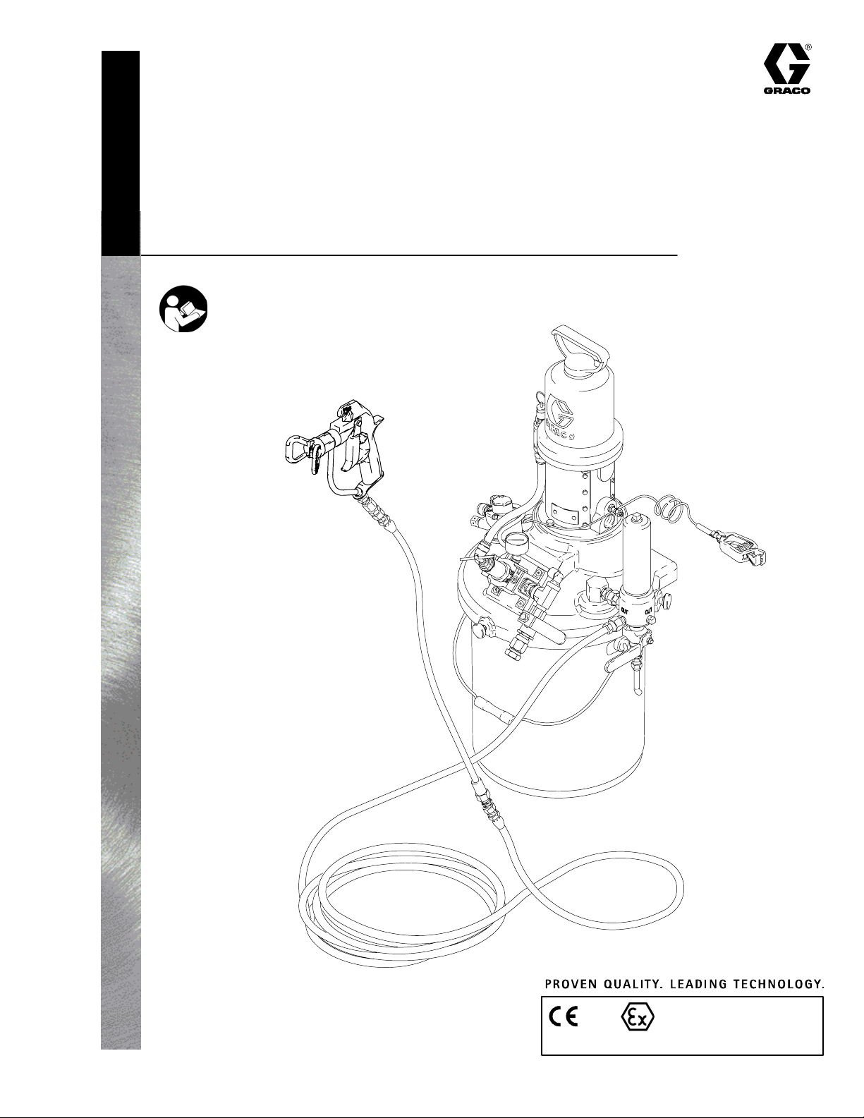
Instructions – Parts List
Pail Mount
Airless Packages
Important Safety Instructions
Read all warnings and instructions in this manual.
Save these instructions.
See page 2 for table of contents.
308765F
GRACO INC. P.O. BOX 1441 MINNEAPOLIS, MN 55440–1441
Copyright 1999, Graco Inc. is registered to I.S. EN ISO 9001
0359
Model 232437 Shown
8109C
II 1/2 G T3
ITS03ATEX11251
Page 2

Table of Contents
List of Models 2. . . . . . . . . . . . . . . . . . . . . . . . . . . . . . . . . .
Warnings 3. . . . . . . . . . . . . . . . . . . . . . . . . . . . . . . . . . . . . .
Setup 6. . . . . . . . . . . . . . . . . . . . . . . . . . . . . . . . . . . . . . . . .
Operation 10. . . . . . . . . . . . . . . . . . . . . . . . . . . . . . . . . . . .
Maintenance 14. . . . . . . . . . . . . . . . . . . . . . . . . . . . . . . . . .
List of Models
Package
Part No. Series Pump Model Ratio
232433 A Monarkr, carbon steel,
with hose and gun,
without agitator
232434 A Monarkr, carbon steel,
without agitator, hose,
and gun
232437 A Monarkr, carbon steel,
with agitator, hose,
and gun
232445 A Monarkr, stainless steel,
with hose and gun,
without agitator
232446 A Monarkr, stainless steel,
without agitator, hose,
and gun
232449 A Monarkr, stainless steel,
with agitator, hose,
and gun
23:1 2300 psi (16 MPa, 160 bar) 100 psi (0.7 MPa, 7 bar)
23:1 2300 psi (16 MPa, 160 bar) 100 psi (0.7 MPa, 7 bar)
23:1 2300 psi (16 MPa, 160 bar) 100 psi (0.7 MPa, 7 bar)
23:1 2300 psi (16 MPa, 160 bar) 100 psi (0.7 MPa, 7 bar)
23:1 2300 psi (16 MPa, 160 bar) 100 psi (0.7 MPa, 7 bar)
23:1 2300 psi (16 MPa, 160 bar) 100 psi (0.7 MPa, 7 bar)
Parts 15. . . . . . . . . . . . . . . . . . . . . . . . . . . . . . . . . . . . . . . .
Technical Data 18. . . . . . . . . . . . . . . . . . . . . . . . . . . . . . . .
Dimensions 19. . . . . . . . . . . . . . . . . . . . . . . . . . . . . . . . . . .
Graco Warranty 20. . . . . . . . . . . . . . . . . . . . . . . . . . . . . . .
Graco Information 20. . . . . . . . . . . . . . . . . . . . . . . . . . . . .
Maximum Fluid
Working Pressure
Maximum Air
Input Pressure
2 308765
Page 3
Symbols
Warning Symbol
WARNING
This symbol alerts you to the possibility of serious
injury or death if you do not follow the instructions.
WARNING
EQUIPMENT MISUSE HAZARD
Equipment misuse can cause the equipment to rupture or malfunction and result in serious injury.
INSTRUCTIONS
D This equipment is for professional use only.
D Read all instruction manuals, tags, and labels before operating the equipment.
D Use the equipment only for its intended purpose. If you are uncertain about usage, call your Graco
distributor.
D Do not alter or modify this equipment. Use only genuine Graco parts and accessories.
Caution Symbol
CAUTION
This symbol alerts you to the possibility of damage to
or destruction of equipment if you do not follow the
instructions.
D Check equipment daily. Repair or replace worn or damaged parts immediately.
D Do not exceed the maximum working pressure of the lowest rated system component. Refer to the
Technical Data on page 18 for the maximum working pressure of this equipment.
D Use fluids and solvents which are compatible with the equipment wetted parts. Refer to the Tech-
nical Data section of all equipment manuals. Read the fluid and solvent manufacturer’s warnings.
D Route hoses away from traffic areas, sharp edges, moving parts, and hot surfaces. Do not expose
Graco hoses to temperatures above 180_F (82_C) or below –40_F (–40_C).
D Wear hearing protection when operating this equipment.
D Do not lift pressurized equipment.
D Comply with all applicable local, state, and national fire, electrical, and safety regulations.
308765 3
Page 4
WARNING
SKIN INJECTION HAZARD
Spray from the gun, hose leaks, or ruptured components can inject fluid into your body and cause
extremely serious injury, including the need for amputation. Fluid splashed in the eyes or on the skin
can also cause serious injury.
D Fluid injected into the skin might look like just a cut, but it is a serious injury. Get immediate surgi-
cal treatment.
D Do not point the gun at anyone or at any part of the body.
D Do not put your hand or fingers over the spray tip.
D Do not stop or deflect leaks with your hand, body, glove or rag.
D Do not “blow back” fluid; this is not an air spray system.
D Always have the tip guard and the trigger guard on the gun when spraying.
D Check the gun diffuser operation weekly. Refer to the gun manual.
D Be sure the gun trigger safety operates before spraying.
D Lock the gun trigger safety when you stop spraying.
D Follow the Pressure Relief Procedure on page 10 whenever you: are instructed to relieve pres-
sure; stop spraying; clean, check, or service the equipment; and install or clean the spray tip.
D Tighten all fluid connections before operating the equipment.
D Check the hoses, tubes, and couplings daily. Replace worn, damaged, or loose parts immediately.
Permanently coupled hoses cannot be repaired; replace the entire hose.
D Use only Graco approved hoses. Do not remove any spring guard that is used to help protect the
hose from rupture caused by kinks or bends near the couplings.
MOVING PARTS HAZARD
Moving parts, such as the air motor piston and agitator blades, can pinch or amputate your fingers.
D Keep clear of all moving parts when starting or operating the pump.
D Always shut off the agitator and disconnect the air line before you remove the agitator from the pail
or check or repair any part of the agitator.
D Before servicing the equipment, follow the Pressure Relief Procedure on page 10 to prevent the
equipment from starting unexpectedly.
4 308765
Page 5
WARNING
FIRE AND EXPLOSION HAZARD
Improper grounding, poor ventilation, open flames or sparks can cause a hazardous condition and
result in a fire or explosion and serious injury.
D Ground the equipment and the object being sprayed. Refer to Grounding on page 7.
D If there is any static sparking or you feel an electric shock while using this equipment, stop spray-
ing immediately. Do not use the equipment until you identify and correct the problem.
D Provide fresh air ventilation to avoid the buildup of flammable fumes from solvents or the fluid
being sprayed.
D Keep the spray area free of debris, including solvent, rags, and gasoline.
D Electrically disconnect all equipment in the spray area.
D Extinguish all open flames or pilot lights in the spray area.
D Do not smoke in the spray area.
D Do not turn on or off any light switch in the spray area while operating or if fumes are present.
D Do not operate a gasoline engine in the spray area.
TOXIC FLUID HAZARD
Hazardous fluid or toxic fumes can cause serious injury or death if splashed in the eyes or on the skin,
inhaled, or swallowed.
D Know the specific hazards of the fluid you are using.
D Store hazardous fluid in an approved container. Dispose of hazardous fluid according to all local,
state and national guidelines.
D Always wear protective eyewear, gloves, clothing and respirator as recommended by the fluid and
solvent manufacturer.
308765 5
Page 6

Setup
General Information
NOTE: Reference numbers and letters in parentheses
in the text refer to the callouts in the figures and the
parts drawing.
NOTE: Always use Genuine Graco Parts and Accessories, available from your Graco distributor. Refer to
Product Data Sheet 305900. If you supply your own
accessories, be sure they are adequately sized and
pressure-rated for your system.
Fig. 2 is only a guide for selecting and installing system components and accessories. Contact your Graco
distributor for assistance in designing a system to suit
your particular needs.
Prepare the Operator
All persons who operate the equipment must be
trained in the safe, efficient operation of all system
components as well as the proper handling of all fluids.
All operators must thoroughly read all instruction
manuals, tags, and labels before operating the equipment.
The following manuals are included with this equipment:
Prepare the Site
Ensure that you have an adequate compressed air
supply. Refer to the performance charts on page 18 to
find the air consumption of your pump.
Refer to Fig. 2 on page 9. Bring a compressed air
supply line from the air compressor to the pump location. Be sure all air hoses are properly sized and
pressure-rated for your system. Use only electrically
conductive hoses. The air hose (A) should have a 3/8
npsm(m) thread.
Install a bleed-type shutoff valve (B) in the air line to
isolate the air line components for servicing. Install an
air line filter (C) and a moisture trap and drain valve
(D) to help remove moisture and contaminants from
the compressed air supply.
Keep the site clear of any obstacles or debris that
could interfere with the operator’s movement.
Have a grounded, metal pail available for use when
flushing the system.
D 308765, Pail Mount Airless Packages
D 307619, Monark 23:1 CST and SST Pumps
D 307043, Monark Air Motor
D 308686, Air Regulator Kit
D 307273, Fluid Filter
D 306565, Agitator (Models 232437
and 232449 only)
D 311254, Airless Spray Gun
6 308765
Page 7

Setup
Grounding
WARNING
FIRE AND EXPLOSION HAZARD
Before operating the pump, ground the
system as explained below. Also read
the section FIRE AND EXPLOSION
HAZARD on page 5.
1. Pump: use the ground wire and clamp (supplied).
See Fig. 1. Loosen the grounding lug locknut (W)
and washer (X). Insert one end of the ground wire
(18) into the slot in lug (Z) and tighten the locknut
securely. Connect the other end of the wire to a
true earth ground.
2. Agitator (Models 232437 and 232449 only): one
end of the agitator ground wire (40, supplied) is
fastened to the agitator motor with a screw. Insert
the other end of the ground wire into the slot in lug
(Z). Insert the pump ground wire (18) as described
in step 1 and tighten the locknut (W) securely.
1 Models with agitator only.
3. Air and fluid hoses: use only electrically conductive
hoses.
4. Air compressor: follow manufacturer’s recommendations.
5. Spray gun: ground through connection to a properly grounded fluid hose and pump.
6. Fluid supply container: follow your local code.
7. Object being sprayed: follow your local code.
8. Solvent pails used when flushing: follow your local
code. Use only metal pails, which are conductive,
placed on a grounded surface. Do not place the
pail on a nonconductive surface, such as paper or
cardboard, which interrupts the grounding continuity.
9. To maintain grounding continuity when flushing or
relieving pressure, hold a metal part of the spray
gun firmly to the side of a grounded metal pail,
then trigger the gun.
1
Fig. 1
40
18
Z
X
W
8238A
308765 7
Page 8

Setup
Supplied Components
Refer to Fig. 2.
WARNING
A red-handled bleed-type master air valve (E) and
a fluid drain valve (F) are supplied. These components help reduce the risk of serious injury, including fluid injection and splashing of fluid in the eyes
or on the skin, and injury from moving parts if you
are adjusting or repairing the pump.
The bleed-type master air valve relieves air trapped
between this valve and the pump after the valve is
closed. Trapped air can cause the pump to cycle
unexpectedly. Locate the valve close to the pump.
The fluid drain valve assists in relieving fluid pressure in the displacement pump, hose, and gun.
Triggering the gun to relieve pressure may not be
sufficient.
D The red-handled bleed-type master air valve (E)
is required in your system to relieve air trapped
between it and the air motor and gun when the
valve is closed (see the WARNING above). Do not
block access to the valve.
D The air relief valve (15) opens automatically to
prevent overpressurization of the pump.
D The air inlet swivel (H) connects incoming air to
the pump.
D The strainer (42) keeps large particles from enter-
ing the pump.
D The fluid filter (13) includes a 60 mesh (250
micron) stainless steel element to filter particles
from the fluid as it leaves the pump. It also includes
the fluid drain valve (F), which is required in your
system to relieve fluid pressure in the hose and gun
(see the WARNING at left).
D The agitator (39), included on Models 232437 and
232449 only, keeps the fluid in suspension.
D The airless spray gun (106) dispenses the fluid.
The gun houses the spray tip (107), which is
available in a wide range of sizes for different spray
patterns and rates of flow.
D The fluid hose (101) and whip hose (103) supply
fluid to the gun.
D The pump air regulator (G) controls pump speed
and outlet pressure by adjusting the air pressure to
the pump.
D The gun swivel (104) allows greater gun maneu-
verability. The swivel includes an in-line filter.
8 308765
Page 9

Setup
B
Model 232437 Shown
KEY
SUPPLIED COMPONENTS
1 5 Gallon (19 liter) Pail Cover
2 Pump
13 Fluid Filter
(includes fluid drain valve F)
15 Air Relief Valve
18 Pump Ground Wire (required;
see page 7 for installation instructions)
19 5 Gallon (19 liter) Pail
39 Agitator
40 Agitator Ground Wire
101 Electrically Conductive Fluid Hose
103 Fluid Whip Hose
104 Gun Filter/Swivel
106 Airless Spray Gun
E* Red-Handled Bleed-Type
Master Air Valve (required, for pump)
F Fluid Drain Valve
G* Pump Air Regulator
H* Air Inlet Swivel
* Included in Air Regulation Kit (21).
COMPONENTS YOU MUST SUPPLY
A Electrically Conductive Air Supply Hose
B Bleed-Type Master Air Valve
(for accessories)
C Air Line Filter
D Air Line Moisture Trap and Drain Valve
C
D
A
106
15
2
40
39
18
104
13
*G
1
F
103
Fig. 2
H*
19
E*
101
8108C
308765 9
Page 10

Operation
Pressure Relief Procedure
WARNING
SKIN INJECTION HAZARD
The system pressure must be manually
relieved to prevent the system from
starting or spraying accidentally. Fluid
under high pressure can be injected through the
skin and cause serious injury. To reduce the risk of
an injury from injection, splashing fluid, or moving
parts, follow the Pressure Relief Procedure
whenever you:
D are instructed to relieve the pressure,
D stop spraying,
D check or service any of the system equipment,
D or install or clean the spray tip.
1. Lock the gun trigger safety.
6. Open the drain valve (F, required in your system),
having a container ready to catch the drainage.
7. Leave the drain valve open until you are ready to
spray again.
If you suspect that the spray tip or hose is completely
clogged, or that pressure has not been fully relieved
after following the steps above, very slowly loosen the
tip guard retaining nut or hose end coupling and relieve
pressure gradually, then loosen completely. Now clear
the tip or hose.
Packing Nut
Before starting, fill the packing nut 1/3 full with Graco
Throat Seal Liquid (TSL) or compatible solvent. See
your separate pump manual.
WARNING
To reduce the risk of serious injury whenever you
are instructed to relieve pressure, always follow the
Pressure Relief Procedure at left.
2. Close the red-handled bleed-type master air valve
(E, required in your system). See Fig. 3 on page
13.
3. Unlock the gun trigger safety.
4. Hold a metal part of the gun firmly to the side of a
grounded metal pail, and trigger the gun to relieve
pressure.
5. Lock the gun trigger safety.
The packing nut is torqued at the factory and is ready
for operation. If it becomes loose and there is leaking
from the throat packings, relieve pressure, then torque
the nut as specified in your separate pump manual. Do
this whenever necessary. Do not overtighten the
packing nut.
Flush the Pump Before First Use
The pump is tested with lightweight oil, which is left in
to protect the pump parts. If the fluid you are using
may be contaminated by the oil, flush it out with a
compatible solvent. See Flushing on page 14.
10 308765
Page 11

Operation
Prime the Pump
1. See Fig. 3. Remove the tip guard and spray tip
from the gun (106). Refer to the gun manual.
2. Close the pump air regulator (G), and bleed-type
air valves (B, E).
3. Connect the air line (A) to the air inlet swivel (H).
4. Check that all fittings throughout the system are
tightened securely.
5. Fill the pail (19) with fluid. Make sure the pail cover
(1) is fastened securely to the pail with the screw
knobs (20).
6. Close the fluid drain valve (F).
7. Hold a metal part of the gun (106) firmly to the side
of a grounded metal pail and hold the trigger open.
8. Open the bleed-type air valves (B, E). Slowly open
the pump air regulator (G) until the pump starts.
9. Cycle the pump slowly until all air is pushed out
and the pump and hoses are fully primed.
10. Release the gun trigger and lock the trigger safety.
The pump should stall against pressure.
Agitator Operation (Models 232437 and
232449)
1. Slowly open the control valve (J) to start the
agitator (39). See Fig. 3.
2. Use the valve (J) to adjust the speed. Do not
operate the agitator too fast. If the fluid foams or a
vortex forms on the fluid surface, reduce the speed
of the agitator.
3. Refer to manual 306565 for further agitator operating instructions.
Install the Spray Tip
WARNING
To reduce the risk of serious injury whenever you
are instructed to relieve pressure, always follow the
Pressure Relief Procedure on page 10.
11. If the pump fails to prime properly, open the drain
valve (F). Use the drain valve as a priming valve
until the fluid flows from the valve. Close the valve.
NOTE: When changing fluid containers with the hose
and gun already primed, open the drain valve (F) to
help prime the pump and vent air before it enters the
hose. Close the drain valve when all air is eliminated.
Relieve the pressure. Install the spray tip and tip guard
as explained in your separate gun manual, supplied.
The spray tip shapes the fluid into a fan pattern. The
orifice size determines the flow rate, and the orifice
shape determines the width of the fan pattern.
308765 11
Page 12

Operation
Adjust the Spray Pattern
1. Start the pump. Use the pump air regulator (G) to
adjust the pump speed and fluid pressure until the
spray is completely atomized. Use the lowest
pressure necessary to get the desired results.
Higher pressure may not improve the spray pattern
and will cause premature tip and pump wear. See
Fig. 3.
WARNING
COMPONENT RUPTURE HAZARD
To reduce the risk of overpressurizing
your package, which could cause component rupture and serious injury, never
exceed 100 psi (0.7 MPa, 7 bar) air input pressure
to the package. Also refer to the Technical Data
on page 18 and to your separate component manuals.
2. Use a full-open, full-close triggering action. Hold
the gun about 14 in. (350 mm) from and at right
angles to the work surface. Move the gun in a
straight stroke; do not swing the gun in an arc.
Practice to find the best length and speed of
stroke.
3. If adjusting the pressure does not give a good
spray pattern, relieve the pressure and try another
tip size. When more coverage is needed, use a
larger spray tip rather than increasing the fluid
pressure.
4. With the pump and lines primed, and with adequate air pressure and volume supplied, the pump
will start and stop as you open and close the gun.
CAUTION
Do not allow the pump to run dry. It will quickly
accelerate to a high speed, causing damage. If your
pump is running too fast, stop it immediately and
check the fluid supply. If the container is empty and
air has been pumped into the lines, refill the container and prime the pump and the lines, or flush and
leave it filled with a compatible solvent. Eliminate all
air from the fluid system.
Shutdown and Care of the Pump
WARNING
To reduce the risk of serious injury whenever you
are instructed to relieve pressure, always follow the
Pressure Relief Procedure on page 10.
For overnight shutdown, stop the pump at the bottom
of its stroke to prevent fluid from drying on the exposed displacement rod and damaging the throat
packings. Shut off the agitator (39), if present. Relieve
the pressure.
Always flush the pump before the fluid dries on the
displacement rod. See Flushing on page 14.
12 308765
Page 13

B
Model 232437 Shown
KEY
1 5 Gallon (19 liter) Pail Cover
2 Pump
13 Fluid Filter
(includes fluid drain valve F)
19 5 Gallon (19 liter) Pail
20 Screw Knobs
39 Agitator
41 Agitator Air Supply Tube
101 Electrically Conductive Fluid Hose
103 Fluid Whip Hose
104 Gun Filter/Swivel
106 Airless Spray Gun
A Electrically Conductive Air Supply Hose
B Bleed-Type Master Air Valve
(for accessories)
E Red-Handled Bleed-Type
Master Air Valve (required, for pump)
F Fluid Drain Valve
G Pump Air Regulator
H Air Inlet Swivel
J Agitator Control Valve
Operation
A
106
39
J
41
104
G
1
20
2
40
13
F
Fig. 3
103
19
H
E
101
8108B
308765 13
Page 14

Maintenance
Preventive Maintenance Schedule
The operating conditions of your particular system
determine how often maintenance is required. Establish a preventive maintenance schedule by recording
when and what kind of maintenance is needed, and
then determine a regular schedule for checking your
system.
Clean the In-Line Fluid Filter Element
The filter/swivel (104) includes a 100 mesh stainless
steel filter element (105). Clean the element periodically with a compatible solvent, as follows.
WARNING
To reduce the risk of serious injury whenever you
are instructed to relieve pressure, always follow the
Pressure Relief Procedure on page 10.
1. Relieve the pressure.
2. Disassemble the filter/swivel (104) and remove the
filter element (105).
3. Clean or replace the element, as necessary.
Flush with a fluid that is compatible with the fluid you
are pumping and with the wetted parts in your system.
Check with your fluid manufacturer or supplier for
recommended flushing fluids and flushing frequency.
CAUTION
If you have a carbon steel package, never leave
water or water-base fluid in the pump overnight. If
you are pumping water-base fluid, flush with water
first, then with a rust inhibitor such as mineral spirits.
Relieve the pressure, but leave the rust inhibitor in
the pump to protect the parts from corrosion.
WARNING
To reduce the risk of serious injury whenever you
are instructed to relieve pressure, always follow the
Pressure Relief Procedure on page 10.
1. Relieve the pressure.
2. Remove the tip guard and spray tip from the gun.
Refer to the gun instruction manual.
4. Reassemble. Torque the two halves of the filter/
swivel to 10–15 ft-lb (14–20 NSm).
Flushing
WARNING
FIRE AND EXPLOSION HAZARD
Before flushing, read the section FIRE
AND EXPLOSION HAZARD on page
5. Be sure the entire system and flushing pails are properly grounded. Refer to
Grounding on page 7.
Flush the pump:
D Before the first use
D When changing colors or fluids
D Before fluid can dry or settle out in a dormant pump
(check the pot life of catalyzed fluids)
D Before storing the pump.
3. Remove the filter element from the fluid filter (13).
Reinstall the filter bowl.
4. Remove the strainer (42). Place the pump inlet in a
container of solvent.
5. Hold a metal part of the gun firmly to the side of a
grounded metal pail.
6. Start the agitator and run it slowly.
7. Start the pump. Always use the lowest possible
fluid pressure when flushing.
8. Trigger the gun. Flush the system until clear
solvent flows from the gun.
9. Relieve the pressure.
10. Clean the tip guard, spray tip, strainer, and fluid
filter element separately, then reinstall them.
14 308765
Page 15

Parts
Part No. 232433, Series A, 23:1 Monark, cst, without agitator, with hose and gun
Part No. 232434, Series A, 23:1 Monark, cst, without agitator, hose, and gun
Part No. 232437, Series A, 23:1 Monark, cst, with agitator, hose, and gun (shown)
Part No. 232445, Series A, 23:1 Monark, sst, without agitator, with hose and gun
Part No. 232446, Series A, 23:1 Monark, sst, without agitator, hose, and gun
Part No. 232449, Series A, 23:1 Monark, sst, with agitator, hose, and gun
NOTE: To find the part number used in your package, read down the chart to find the desired ref. no., then read left
to right to find the part number for your package.
Packages
Ref.
No. Description
1 COVER, pail 240435 240435 240435 240435 1
2 PUMP, 23:1 Monark; cst; see manual 307619 223596 223596 1
PUMP, 23:1 Monark; sst; see manual 307619 237958 237958 1
3 CAPSCREW, hex hd; 1/4–20 x 3/4 in. (19 mm) 100644 100644 100644 100644 2
4 LOCKWASHER; 1/4 in. 100016 100016 100016 100016 2
5 ELBOW, 90_; cst; 3/8 npt(m) x 3/8 npt(f) 155699 155699 1
ELBOW, 90_; sst; 3/8 npt(m) x 3/8 JIC 114484 114484 1
6 ADAPTER; cst; 3/8 npt x 9/16–18 unf–2a 114337 114337 Not used Not used 1
7 TUBE, flare; sst; 9/16–18 unf–2a x 3/8 in. (10 mm) OD 114478 114478 1
TUBE, flare; sst; 9/16–18 unf–2a x 3/8 in. (10 mm) OD 114477 114477 1
8 FITTING, bulkhead 192889 192889 192889 192889 1
9 WASHER, flat; 9/16 in. 114830 114830 114830 114830 1
10 NUT, hex; 9/16–18 102300 102300 102300 102300 1
11 NIPPLE; cst; 3/8 npt 156849 156849 1
NIPPLE; sst; 3/8 npt 166469 166469 1
12 UNION, swivel, straight; cst; 3/8 npt(m) x 3/8 npsm(f) 155665 155665 1
UNION, swivel, straight; sst; 3/8 npt(m) x 3/8 npsm(f) 235208 235208 1
13 FLUID FILTER; cst; see manual 307273 239060 239060 1
FLUID FILTER; sst; see manual 307273 239063 239063 1
14 TEE; 3/8 npt(f) run x 3/8 npt(m) branch 113777 113777 113777 113777 1
15 VALVE, relief; 125 psi (0.86 MPa, 8.6 bar) 113769 113769 113769 113769 1
16 CONNECTOR, tube fitting;
3/8 npt(m) x 1/2 in. (13 mm) OD tube
17 TUBE; polyurethane; 1/2 in. (13 mm) OD; 1.3 ft (0.4 m) long Obtain
18 PUMP GROUND WIRE AND CLAMP 238909 238909 238909 238909 1
19 PAIL; 5 gallon (19 liter) 101108 101108 101108 101108 1
20 KNOB, screw; 1/4–20 114371 114371 114371 114371 3
21 AIR REGULATOR KIT; see manual 308686 240231 240231 240231 240231 1
22 SCREW, socket; M5 x 0.8; 20 mm (3/4 in.) 115439 115439 115439 115439 4
23 NUT, hex, self-locking; M5 x 0.8 105332 105332 105332 105332 4
24 QUICK CONNECTOR, elbow, 90_, tube;
1/8 npt(m) x 1/4 in. (6 mm) OD tube; acetal
25 WASHER, flat 110874 110874 110874 110874 4
CST
232433,
232434
114129 114129 114129 114129 1
locally
Not used 114367 Not used 114367 1
CST
232437
Obtain
locally
SST
232445,
232446
Obtain
locally
SST
232449
Obtain
locally
Qty
1
308765 15
Page 16

Parts
Part No. 232433, Series A, 23:1 Monark, cst, without agitator, with hose and gun
Part No. 232434, Series A, 23:1 Monark, cst, without agitator, hose, and gun
Part No. 232437, Series A, 23:1 Monark, cst, with agitator, hose, and gun (shown)
Part No. 232445, Series A, 23:1 Monark, sst, without agitator, with hose and gun
Part No. 232446, Series A, 23:1 Monark, sst, without agitator, hose, and gun
Part No. 232449, Series A, 23:1 Monark, sst, with agitator, hose, and gun
NOTE: To find the part number used in your package, read down the chart to find the desired ref. no., then read left
to right to find the part number for your package.
Packages
Ref.
No. Description
30 SCREW, set; 1/4–20 x 1/4 in. (6 mm) 101962 101962 101962 101962 2
31 PLUG, pipe; 3/8 npt; not shown 100040 100040 1
ELBOW, tube fitting, 90_; 3/8 npt(m) x 1/4 in. (6 mm) OD tube 114366 114366 1
39 PLUG, agitator; not shown 114575 114575 1
AGITATOR; see manual 306565 224571 224571 1
40 AGITATOR GROUND WIRE Not used 240585 Not used 240585 1
41 TUBE; nylon; 1/4 in. (6 mm) OD; 10 in. (254 mm) long Not used Obtain
42 STRAINER, fluid inlet 187190 187190 187190 187190 1
CST
232433,
232434
CST
232437
locally
SST
232445,
232446
Not used Obtain
SST
232449
locally
Qty
1
Hose and Gun Parts
Part No. 232433, Series A, 23:1 Monark, cst, without agitator, with hose and gun
Part No. 232437, Series A, 23:1 Monark, cst, with agitator, hose, and gun (shown)
Part No. 232445, Series A, 23:1 Monark, sst, without agitator, with hose and gun
Part No. 232449, Series A, 23:1 Monark, sst, with agitator, hose, and gun
NOTE: The following part numbers apply only to packages supplied with a hose and gun. Part numbers vary by
package. To find the part number used in your package, read down the chart to find the desired ref. no., then read
left to right to find the part number for your package.
Packages
Ref.
No. Description
101 HOSE, fluid; nylon; cst fluid fittings;1/4 npsm (fbe);
1/4 in. (6 mm) ID; 25 ft (7.6 m) long
HOSE, fluid; nylon; sst fluid fittings;1/4 npsm (fbe);
1/4 in. (6 mm) ID; 24.6 ft (7.5 m) long
102 NIPPLE; cst; 1/4 npt x 1/4 npsm 162453 162453 1
NIPPLE; sst; 1/4 npt x 1/4 npsm 166846 166846 1
103 HOSE, whip, fluid; nylon; cst fittings; 1/4 npsm (fbe);
3/16 in. (5 mm) ID; 23.6 in. (0.6 m) long
HOSE, whip, fluid; nylon; sst fittings; 1/4 npsm (fbe);
3/16 in. (5 mm) ID; 23.6 in. (0.6 m) long
104 FILTER/SWIVEL, gun; includes replaceable item 105 1
105 . ELEMENT, filter; 100 mesh sst; not shown 205264 205264 205264 205264 1
106 AIRLESS SPRAY GUN, for fine finish;
see manual 311254
107 FINE FINISH SPRAY TIP, silver; customer’s choice;
not shown
CST
232433
H42525 H42525 1
238708 238708 1
XTR501 XTR501 XTR501 XTR501 1
16 308765
CST
232437
SST
232445
239107 239107 1
239069 239069 1
SST
232449
Qty
1
Page 17

Parts
Part No. 232437, Series A, 23:1 Monark, carbon steel (shown)
15
106
17 (Ref)
22
21
14
16
17
40 (Ref)
24
39
41 (Ref)
D
B
31
30
41
2
3
4
18
D
E
B
E
40
5
6
7
A
42
1
8
11
12
13
104
103
C
23, 25
20
19
102
101
A
7 (Ref)
9
10
C
8107B
8107C
308765 17
Page 18

Technical Data
Category Data
Maximum fluid working pressure 2300 psi (16 MPa, 160 bar)
Maximum air input pressure 100 psi (0.7 MPa, 7 bar)
Ratio 23:1
Maximum operating temperature 120_F (50_C)
Wetted parts Pump: See pump manual 307619
Spray Gun: See gun manual 311254
Fluid Filter: See filter manual 307273
Agitator: See agitator manual 306565
Fluid Hoses: Nylon
Sound Pressure Levels (dBa)
(measured at 1 meter from unit)
Input Air Pressures at 15 cycles per minute
Air Motor 40 psi (0.28 MPa, 2.8 bar) 70 psi (0.48 MPa, 4.8 bar) 100 psi (0.7 MPa, 7 bar)
Monark 73.3 dB(A) 75.9 dB(A) 77.7 dB(A)
Sound Power Levels (dBa)
(tested in accordance with ISO 9614–2)
Input Air Pressures at 15 cycles per minute
Air Motor 40 psi (0.28 MPa, 2.8 bar) 70 psi (0.48 MPa, 4.8 bar) 100 psi (0.7 MPa, 7 bar)
Monark 87.0 dB(A) 89.7 dB(A) 91.4 dB(A)
Performance Charts
To find Fluid Outlet Pressure (psi/MPa/bar) at a specific fluid flow
(lpm/gpm) and operating air pressure (psi/MPa/bar):
1. Locate desired flow along bottom of chart.
2. Follow vertical line up to intersection with selected fluid outlet
pressure curve (black). Follow left to scale to read fluid outlet
pressure.
A 100 psi (0.7 MPa, 7 bar) air pressure
B 70 psi (0.49 MPa, 4.9 bar) air pressure
C 40 psi (0.28 MPa, 2.8 bar) air pressure
Monark 23:1 Fluid Outlet Pressure
psi
MPa, bar
3000
21, 210
2250
15.8, 158
1500
10.4,104
750
FLUID PRESSURE
5.1, 51
0
0.0 0.1 0.2 0.3 0.4 0.5
gpm
liters/minute
FLUID FLOW (TEST FLUID: NO. 10 WEIGHT OIL)
A
B
C
cycles per minute
15 30 45 7560
0.4 0.8 1.2 1.5 1.9
18 308765
To find Pump Air Consumption (m#/min or scfm) at a specific fluid
flow (lpm/gpm) and air pressure (psi/MPa/bar):
1. Locate desired flow along bottom of chart.
2. Read vertical line up to intersection with selected air consumption
curve (dashes). Follow left to scale to read air consumption.
Monark 23:1 Air Consumption
scfm
m#/min
10
0.28
0.22
0.17
0.11
AIR CONSUMPTION
.056
gpm
liters/minute
8
6
4
2
0
0.0 0.1 0.2 0.3 0.4 0.5
FLUID FLOW (TEST FLUID: NO. 10 WEIGHT OIL)
cycles per minute
15 30 45 7560
A
B
C
0.4 0.8 1.2 1.5 1.9
Page 19

Model 232437 Shown
(hose and gun not shown)
Dimensions
A
B
A (height) B (diameter of pail) Weight
32 in. (813 mm) 10.625 in. (270 mm) 47 lb (21 kg)
8110A
308765 19
Page 20

Graco Standard Warranty
Graco warrants all equipment manufactured by Graco and bearing its name to be free from defects in material and workmanship on the
date of sale to the original purchaser for use. With the exception of any special, extended, or limited warranty published by Graco,
Graco will, for a period of twelve months from the date of sale, repair or replace any part of the equipment determined by Graco to be
defective. This warranty applies only when the equipment is installed, operated and maintained in accordance with Graco’s written
recommendations.
This warranty does not cover, and Graco shall not be liable for general wear and tear, or any malfunction, damage or wear caused by
faulty installation, misapplication, abrasion, corrosion, inadequate or improper maintenance, negligence, accident, tampering, or substitution of non–Graco component parts. Nor shall Graco be liable for malfunction, damage or wear caused by the incompatibility of
Graco equipment with structures, accessories, equipment or materials not supplied by Graco, or the improper design, manufacture,
installation, operation or maintenance of structures, accessories, equipment or materials not supplied by Graco.
This warranty is conditioned upon the prepaid return of the equipment claimed to be defective to an authorized Graco distributor for
verification of the claimed defect. If the claimed defect is verified, Graco will repair or replace free of charge any defective parts. The
equipment will be returned to the original purchaser transportation prepaid. If inspection of the equipment does not disclose any defect
in material or workmanship, repairs will be made at a reasonable charge, which charges may include the costs of parts, labor, and
transportation.
THIS WARRANTY IS EXCLUSIVE, AND IS IN LIEU OF ANY OTHER WARRANTIES, EXPRESS OR IMPLIED, INCLUDING BUT
NOT LIMITED TO WARRANTY OF MERCHANTABILITY OR WARRANTY OF FITNESS FOR A PARTICULAR PURPOSE.
Graco’s sole obligation and buyer’s sole remedy for any breach of warranty shall be as set forth above. The buyer agrees that no other
remedy (including, but not limited to, incidental or consequential damages for lost profits, lost sales, injury to person or property, or any
other incidental or consequential loss) shall be available. Any action for breach of warranty must be brought within two (2) years of the
date of sale.
Graco makes no warranty, and disclaims all implied warranties of merchantability and fitness for a particular purpose in connection
with accessories, equipment, materials or components sold but not manufactured by Graco. These items sold, but not manufactured
by Graco (such as electric motors, switches, hose, etc.), are subject to the warranty, if any, of their manufacturer. Graco will provide
purchaser with reasonable assistance in making any claim for breach of these warranties.
In no event will Graco be liable for indirect, incidental, special or consequential damages resulting from Graco supplying equipment
hereunder, or the furnishing, performance, or use of any products or other goods sold hereto, whether due to a breach of contract,
breach of warranty, the negligence of Graco, or otherwise.
FOR GRACO CANADA CUSTOMERS
The parties acknowledge that they have required that the present document, as well as all documents, notices and legal proceedings
entered into, given or instituted pursuant hereto or relating directly or indirectly hereto, be drawn up in English. Les parties reconnaissent avoir convenu que la rédaction du présente document sera en Anglais, ainsi que tous documents, avis et procédures judiciaires
exécutés, donnés ou intentés à la suite de ou en rapport, directement ou indirectement, avec les procedures concernées.
Graco Information
TO PLACE AN ORDER, contact your Graco distributor, or call one of the following numbers
to identify the distributor closest to you:
1–800–328–0211 Toll Free
612–623–6921
612–378–3505 Fax
All written and visual data contained in this document reflects the latest product information available at the time of publication.
Graco reserves the right to make changes at any time without notice.
20 308765
This manual contains English. MM 308765
Graco Headquarters: Minneapolis
International Offices: Belgium, China, Japan, Korea
GRACO INC. P.O. BOX 1441 MINNEAPOLIS, MN 55440–1441
www.graco.com
05/1999 Revised 05/2007
 Loading...