

Page 1
SOLID STATE COLOR TV
OPERATING GUIDE
IMPORTANT SAFEGUARDS 2-5
I_il
i
D
FIRST TIME USE 6-17
THE REMOTE CONTROL 18-31
EASY GRAPHIC GUIDE 32 - 45
USEFUL INFORMATION
INDEX
46-51
Page 2

IMPORTANT
Your new HITACHI COLOR TV incorporates a host of features designed to give you excellent performance ifyou follow
the instructions in this manual. We recommend that you read the following instructions and "IMPORTANT SAFE-
GUARDS" notice before turning on your TV set for the first time.
Follow all warnings and instructions marked on this television receiver.
The lightning flashwith arrowheadsymbol, within an
equilateraltriangle,is intendedtoalerttheusertothe
,_ RISKOF ELECTRIC SHOCK
CAUTION: TO REDUCE THE RISK OF ELECTRIC SHOCK,
REFER SERVICING TO QUALIFIED SERVICE PERSONNEL.
I c.o..o,la,
DO NOT REMOVE COVER (OR BACK)
NO USER-SERVICEABLE PARTS INSIDE.
DO NOTOPEN
WARNING:
TO PREVENT FIRE OR SHOCK HAZARD, DO NOT
EXPOSE THIS TELEVISION SYSTEM TO RAIN OR MOISTURE.
presenceofuninsulated"dangerous voltage"within
the product'senclosure that may be of sufficient
magnitudeto constitutea risk of electricshockto
persons.
The exclamationpolr_twithinanequilateraltriangleis
Intendedtoalertthe usertothepresenceofimportant
operatingandmaintenance(servicing)instructionsin
the literatureaccompanyingtheappliance.
NOTE:
POWER SOURCE:
This HITACHI color TV is designed to operate on 120 volts 60 Hz, AC household current.
Insert power cord into a 120 volt 60 Hz outlet.
TO PREVENT ELECTRIC SHOCK, DO NOT USE THE TELEVISION'S PLUG WITH AN EXTENSION CORD,
RECEPTACLE, OR OTHER OUTLET UNLESS THE BLADES AND GROUND TERMINAL CAN BE FULLY
INSERTED TO PREVENT BLADE EXPOSURE.
NEVER CONNECT THE TV TO 50 Hz, DIRECT CURRENT, OR ANYTHING OTHER THAN THE SPECIFIED
VOLTAGE.
I NOTE: This television receiver will display television closed captioning, (B orl_), in accordance with
• There are no user serviceable parts inside the receiver.
• Model number and serial number are indicated on back side of the set.
paragraph 15.119 of the FCC rules.
2
Page 3

SAFETY TIPS
IMPORTANT SAFEGUARDS
CAUTION: SAFETY POINTS YOU SHOULD KNOW ABOUT
* Read all of these instructions YOUR HITACHI TELEVISION RECEIVER
* Save these instructions for later use.
* Follow all warnings and instructions marked on the television receiver.
Our reputation has been built on the quality, performance, and ease of service of HITACHI television receivers.
Safety is also foremost in our minds in the design of these units. To help you operate these products properly, this folder illustrates safety tips which will be of benefit
to you. Please read it carefully and apply the knowledge you obtain from it to the proper operation of your HITACHI television receiver.
Please fill out your warranty card at once and mail it to HITACHI. This will enable HITACHI to notify you promptly in the improbable event that a safety problem should
be discovered in your model of product.
FOR YOUR PERSONAL SAFETY
1 This television set is equipped with a polarized
alternating-current line plug (a plug having one
blade wider than the other). This plug will fit into
the power outlet only one way. This is a safety
feature. If you are unable to insert the plug fully
into the outlet, try reversing the plug. If the plug
should still fail to fit, contact your electrician to 8
replace your obsolete outlet. Do not defeat the
safety purpose of the polarized plug.
2 When the power cord or plug is damaged or
frayed, unplug this television set from the wall '_ _
outlet and refer servicing to qualified service
personnel. 9
3 Do not overload wall outlets and extension cords
as this can result in fire or electric shock.
Do not allow anything to rest on or roll over the I_ _,._v'
power cord, and do not place the TV where the
power cord is subject to traffic or abuse. This
may result in a shock or fire hazard.
Do not attempt to service this television set your-
self as opening or removing covers may expose
you to dangerous voltage or other hazards. Refer
all servicing to qualified service personnel.
Never push objects of any kind into this television
set through cabinet slots as they may touch
dangerous voltage points or short out parts that
could result in a fire or electric shock. Never spill
liquid of any kind on the television set.
If the television set has been dropped or the
cabinet has been damaged, unplug this televi-
sion set from the wall outlet and refer servicing to
qualified service personnel.
I1liquid has been spilled into this television set,
unplug it from the wall outlet and refer service to
qualified service personnel.
Do not subject your television set to impact of any
kind. Be particularly careful not to damage the
picture tube surface.
10
Unplug this television set from the wall outlet
before cleaning . Do not use liquid cleaners or
aerosol cleaners. Use a damp cloth for cleaning,
11-1
Do not place this television set on an unstable
cart, stand, or table. The television set may fall,
causing serious injury to a child or an adult, and
serious damage to the appliance. Use only with
a cart or stand recommended by the manufac-
turer, or sold with the television set. Wall or shelf
mounting should follow the manufacturer's in-
structions, and should use a mounting kit ap-
proved by the manufacturer.
i.i
11-2
An appliance and cart combination should be
moved with care. Quick stops, excessive force,
and uneven surfaces may cause the appliance
and cart combination to overturn.
@
/;
PROTECTION AND LOCATION OF YOUR SET
12 Do not use this television set near water, for
example, near a bathtub, washbowl, kitchen sink,
or laundry tub, in a wet basement, or near a
swimming pool, etc.
Never expose the set to rain or water. If the set
has been exposed to rain or water, unplug the set
from the wall outlet and refer to servicing person-
nel.
13 Choose a place where light (artificial or sunlight)
does not shine directly on the screen.
14 Avoid dusty places, since accumulated dust
inside the chassis may cause failure of the set
when high humidity persists.
15
The set has slots, or openings in the cabinet for
ventilation purposes, to provide reliable opera-
tion of the receiver, and to protect from overheat-
ing. These openings must not be blocked or
covered.
Never cover the slots or openings with cloth or
other material.
Never block the bottom ventilation slots of the set
by placing it on a bed, sofa, rug, etc.
Never place the set near or over a radiator or heat
register.
Never place the set in a "built-in" enclosure,
unless proper ventilation is provided.
3
@/
Page 4

SAFETY TIPS
PROTECTION AND LOCATION OF YOUR SET
16-1 If an outside antenna is connected to the televi-
sion set, be sure the antenna system is grounded
so as to provide some protection against voltage
surges and built up static charges, Section 810 of
the National Electrical Code, NFPA No. 70-1975,
provides information with respect to proper
grounding of the mast and supporting structure,
r_OUND
CL_P
EXAMPLE OF ANTENNA GROUNDING AS PER
NATIONAL ELECTRICAL CODE INSTRUCTIONS
OPERATION OF YOUR SET
19
This television set should be operated only from
the type of power source indicated on the marking
label. If you are not sure of the type of power
supply at your home, consult your television dealer
or local power company. For television sets
designed to operate from battery power, refer to
the operating instructions.
NECNATION_ELECTR_C_COOE
ANTENNA
LEAD_N
WIRE
DISCHARGEUNiT
(NECSECTIONB1_20_
l _TENNA
6ROONC_INGCONDUCTORS
(NECSECTION81021)
GROUNDINGCONDUC'rORS
POWERSERVICEGROUNDING
ELECTRODESYSTEM
(NECART25OP_ H)
grounding of the lead-in wire to an antenna dis-
charge unit, size of grounding conductors, loca-
tion of antenna discharge unit, connection to
grounding electrode, and requirements for the
grounding electrode.
16-2
Note to CATV system installer:
(Only for the television set with CATV reception)
This reminder is provided to call the CATV sys-
tem installer's attention to Article 820-40 of the
NEC that provides guidelines for proper ground-
ing and, in particular, specifies that the cable
ground shall be connected to the grounding sys-
tem of the building, as close to the point of cable
entry as practical.
17
An outside antenna system should not be located
in the vicinity of overhead power lines or other
electrical lights or power circuits, or where it can
fall into such power lines or circuits. When
installing an outside antenna system, extreme
care should be taken to keep from touching such
power lines or circuits as contact with them might
be fatal.
For added protection for this television set du ring
a lightning storm, or when it is left unattended and
unused for long periods of time, unplug it from the
wall outlet and disconnect the antenna. This will
prevent damage due to lightning and power-line
surges.
2O
If the television set does not operate normally by
following the operating instructions, unplug this
television set from the wall outlet a nd refer servic-
ing to qualified service personnel. Adjust only
those controls that are covered in the operating
instructions as improper adjustment of other con-
trois may result in damage and will often require
extensive work by a qualified technician to re-
store the television set to normal operation.
21
When going on a holiday: If your television set is
to remain unused for a period of time, turn the
television set "off' and unplug it from the wall
outlet.
IF THE SET DOES NOT OPERATE PROPERLY
22
If you are unable to restore normal operation by
following the detailed procedure in your operat-
ing instructions, do not attempt any further ad-
justment. Unplug the set and call your dealer or
service technician.
FOR SERVICING AND MODIFICATION
25 DO not use attachments not recommended by the
television set manufacturer as they may cause
hazards.
26
When replacement parts are required, be sure
the service technician has used replacement
parts specified by the manufacturer that have the
same characteristics as the original part. Unau-
thorized substitutions may result in fire, electric
shock, or other hazards.
23
Whenever the television set is damaged or fails,
or a distinct change in performance indicates a
need for service, unplug the set and have it
checked by a professional service technician.
24
It is normal for some TV sets to make occasional
snapping or popping sounds, particularly when
being turned on or off. Ifthe snapping or popping
is continuous or frequent, unplug the set and
consult your dealer or service technician.
27
Upon completion of any service or repairs to the
television set, ask the service technician to per-
form routine safety checks to determine that the
television is in safe operating condition.
• . ask
Page 5

PICTURE CAUTIONS
Continuous on-screen displays such as
video games, stock market quotations,
computer generated graphics, and other
fixed (non-moving) patterns can cause per-
WARNING
manent damage to color television receiv-
ers. Such "PATTERN BURNS" constitute
misuse and are NOT COVERED by your
Hitachi Factory Warranty.
When using the Picture-in-Picture function, the sub-picture should not be left permanently
in one corner of the screen or a "pattern burn" may develop over a long period of time.
This Color television receiver was intended mainly for the private viewing of programs
broadcast by TV stations and cable companies and programs from other video sources.
Public viewing may require prior authorization from the broadcaster or owner of the video
program.
Page 6

ACCESSORIES
Check to make sure you have the following accessories before disposing of the packing material.
1. Remote Control Unit (See Part No. Below)
2. Two "AA" size, 1.5V batteries (For Remote Contol Unit)
For information regarding how to obtain these accessories, please call TOLL FREE 1-800-448-2244 for your nearest
HITACHI Authorized Parts Distributor in the continental United States. ForAlaska and Hawaii, please contact your nearest
HITACHI Regional office.
PART NAME
270X6B
CLU-415UI
REMOTE TRANSMITTER
27CX25B/20SA3B
CLU-414UI
REMOTE TRANSMITTER
27CX5B
CLU-412U
REMOTE TRANSMITTER
27V TELEVISION STAND
SP271B
(Not included, order separately)
PART NO.
HL00224
HL00223
HL00221
H530021
[]
cz) c::_ cz_
_] EE3E_
(3) QD(33
O (]D(Z)
6®t3 L
CLU-415UI
F
i
ILLUSTRATION
vcR_m_
(_ EE3EE)
CDGD_ _
c!) G) (D
(!) (_ (io
HI'T_M_kll HI'T/I¢_I
CLU-414UI CLU-412U
CUSTOM HITACHI
TELEVISION STAND
Excellent for VCR and
videotape storage. Special
Features: curved smoke
glass doors, adjustable
_5 c2__
CD (2) C!)
G9 (i) Q
shelf. Available in Black.
,_CAUTION: The television stand model SP271B is designed for use only with HITACHI TV models 27CX5B,
27CX6B, and 27CX25B. Use with other television equipment may result in instability, causing
possible injury.
Page 7

REMOTE CONTROL BATTERY INSTALLATION AND
REPLACEMENT
1.
Open the battery cover of the remote transmitter by
pushing the notched part of the cover with your
fingers.
2,
Insert new "AA" size (SUM-3) batteries or equiva-
lent for the Genius Remote. When replacing old
batteries, push them towards the springs and lift
them out.
3. Match the (+) and (-) marks in the battery compart-
ment.
4. Replace the cover.
BOTTOM VIEW
CAUTIONS
1. Ifyour television set is to remain unused for a long period of time, for instance, when you go on a vacation, unpiug
the television set from the wall outlet.
2. Do not subject the Remote Transmitter to shocks such as dropping it on the floor, etc. Precision parts may be
damaged.
3. Do not allow the Remote Transmitter to become wet and avoid placing itin areas of high humidity. Don't leave
it on or near a heater. Excess heat or moisture may cause the unit to cease operation.
4. If the batteries become exhausted, Remote Control operation may become erratic or stop altogether. Replace
the old batteries with fresh "AA" (SUM-3) types.
NOTES
1. The channel No. indication, volume indication and OFF TIMER indication are not displayed simultaneously.
2. To operate your TV, point the Remote Transmitter at the remote sensor of the TV.
Page 8
HOW 1O SL1 UP YOUR NEW HITACHI COLOR TV
ANTENNA
Unless your TV Jscu_, _uctedto a cable TV system or to a centralized antenna system, a good outdoor color TV antenna
is recommended for the best performance. However, ifyou are located in an exceptionally good signal area that is free
from interference and multiple image ghosts, an indoor antenna may be sufficient.
LOCATION
Select an area where sunlight or bright indoor illumination will not fall directly on the picture screen. Also, be sure that
the location selected allows a free flow of air to and from the cover of the set.
To avoid cabinet warping, cabinet color changes, and increased chance of set failure, do not place the TV where
temperatures can become excessively hot. For example, in direct sunlight or near a heating appliance, etc.
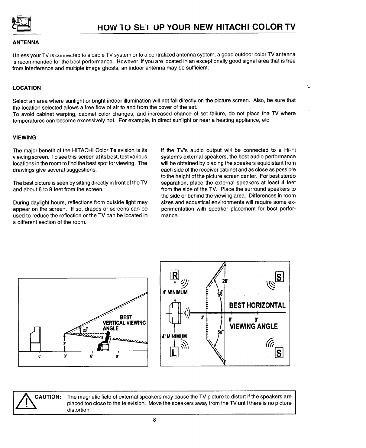
VIEWING
The major benefit of the HITACHI Color Television is its
viewing screen. To see this screen at its best, test various
locations in the room to find the best spot for viewing. The
drawings give several suggestions.
The best picture is seen by sitting directly in front of the TV
and about 6 to 9 feet from the screen.
During daylight hours, reflections from outside light may
appear on the screen. If so, drapes or screens can be
used to reduce the reflection or the TV can be located in
a different section of the room.
If the TV's audio output will be connected to a Hi-Fi
system's external speakers, the best audio performance
will be obtained by placing the speakers equidistant from
each side of the receiver cabinet and as close as possible
to the height of the picture screen center. For best stereo
separation, place the external speakers at least 4 feet
from the side of the TV. Place the surround speakers to
the side or behind the viewing area. Differences in room
sizes and acoustical environments will require some ex-
perimentation with speaker placement for best perfor-
mance.
I _CAUTION:
v
0'
The magnetic field of external speakers may cause the TV picture to distort if the speakers are
placed too close to the television. Move the speakers away from the TV until there is no picture
distortion.
8
Page 9
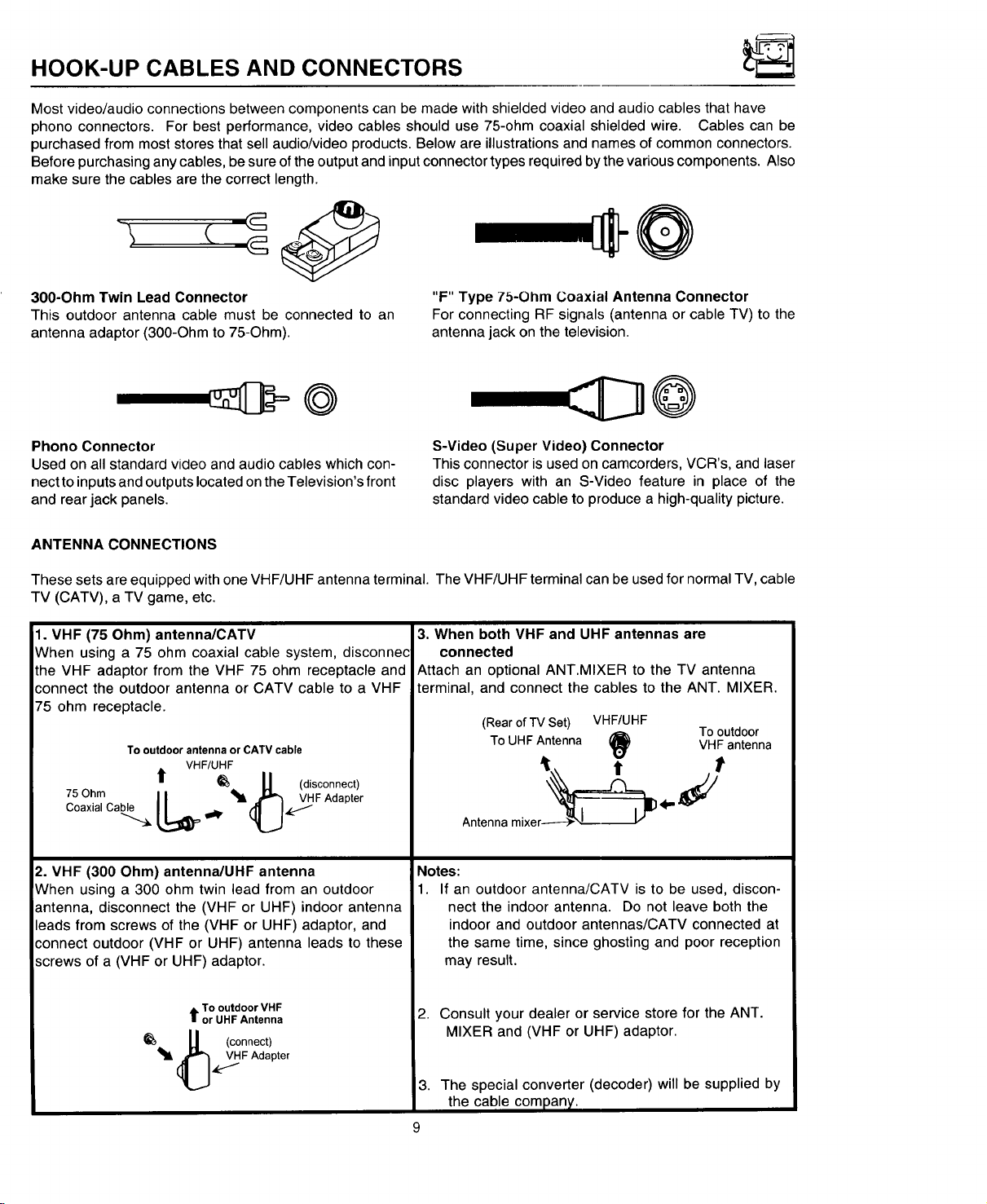
HOOK-UP CABLES AND CONNECTORS
Most video/audio connections between components can be made with shielded video and audio cables that have
phono connectors. For best performance, video cables should use 75-ohm coaxial shielded wire. Cables can be
purchased from most stores that sell audio/video products. Below are illustrations and names of common connectors.
Before purchasing any cables, be sure of the output and input connector types required bythe various components. Also
make sure the cables are the correct length.
=-e@
300-Ohm Twin Lead Connector
This outdoor antenna cable must be connected to an
antenna adaptor (300-Ohm to 75-Ohm).
"F" Type 7b-Ohm Coaxial Antenna Connector
For connecting RF signals (antenna or cable TV) to the
antenna jack on the television.
@
Phono Connector
Used on all standard video and audio cables which con-
nect to inputs and outputs located on the Television's front
and rear jack panels.
ANTENNA CONNECTIONS
These sets are equipped with one VHF/UHF antenna terminal. The VHF/UHF terminal can be used for normal TV, cable
TV (CATV), a TV game, etc.
1. VHF (75 Ohm) antenna/CATV
When using a 75 ohm coaxial cable system, disconnec
the VHF adaptor from the VHF 75 ohm receptacle and
connect the outdoor antenna or CATV cable to a VHF
75 ohm receptacle.
To outdoor antenna or CATV cable
VHF/UHF
t1" __ U (disconnect)
Coaxial Cable
75Ohm L_l! .O_FAdapte r
S-Video (Super Video) Connector
This connector is used on camcorders, VCR's, and laser
disc players with an S-Video feature in place of the
standard video cable to produce a high-quality picture.
3. When both VHF and UHF antennas are
connected
Attach an optional ANT.MIXER to the TV antenna
terminal, and connect the cables to the ANT. MIXER.
(RearofTV Set) VHF/UHF
ToUHFAntenna VHFantenna
Antennamixer------)-_,L .v
i_) Tooutdoor
2. VHF (300 Ohm) antenna/UHF antenna
When using a 300 ohm twin lead from an outdoor
antenna, disconnect the (VHF or UHF) indoor antenna
leads from screws of the (VHF or UHF) adaptor, and
connect outdoor (VHF or UHF) antenna leads to these
screws of a (VHF or UHF) adaptor.
t To outdoor VHF
or UHF Antenna
. U (connect)
_t' (_,4r_F Adapter
Notes:
1. If an outdoor antenna/CATV is to be used, discon-
nect the indoor antenna. Do not leave both the
indoor and outdoor antennas/CATV connected at
the same time, since ghosting and poor reception
may result.
2. Consult your dealer or service store for the ANT.
MIXER and (VHF or UHF) adaptor.
3. The special converter (decoder) will be supplied by
the cable company.
Page 10
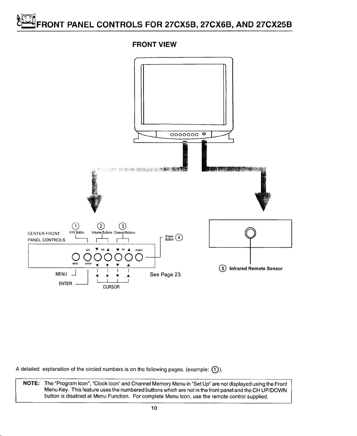
_FRONT PANEL CONTROLS FOR 27CX5B, 27CX6B, AND 27CX25B
FRONT VIEW
0000000 O_
Q ® ®
CENTER FRONT AVXButton Volume Buttons ChannelButtons
PANEL CONTROLS L I Button
AV'X • v0t • • CH • I=OWEI_
oooo9oo
MENU E'_TER • •
/ I I I I
MENU ._1 • • • • See Page 23.
ENTER--
A detailed explanation of the circled numbers is on the following pages. (example: (_)).
NOTE: The "Program Icon", "Clock Icon" and Channel Memory Menu in "Set Up" are not displayed using the Front
Menu Key. This feature uses the numbered buttons which are not in the front panel and the CH UP/DOWN
button is disabled at Menu Function. For complete Menu Icon, use the remote control supplied.
I I I I
CURSOR
Q Infrared Remote Sensor
10
Page 11
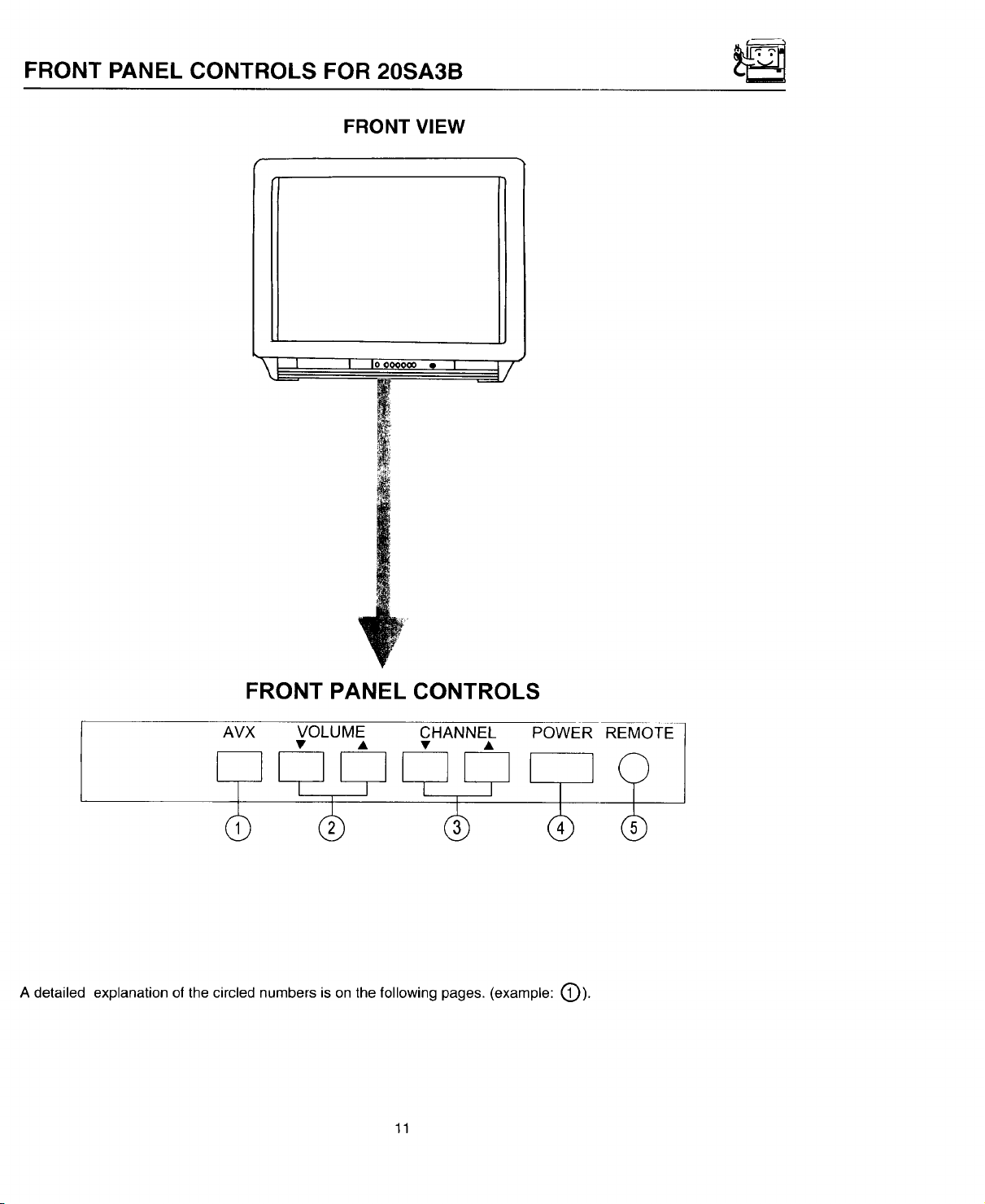
FRONT PANEL CONTROLS FOR 20SA3B
FRONT VIEW
j! , ,ooo_0=., _
FRONT PANEL CONTROLS
_x VOLU% c._..E_ _OWER
A detailed explanation of the circled numbers is on the following pages. (example: t_).
11
REMOTE ]
Page 12

FRONI HANI:::L CONTROLS
(9
AVX (Audio/Video) Selector
Press this button to select the current antenna source or VIDEO: 1. Your selection is shown in the top right corner
of the screen.
Q VOLUME Level
Press these buttons for your desired sound level. The volume level will be displayed on the TV screen.
CHANNEL Selector
Press these buttons until the desired channel appears in the top right corner of the TV screen.
Q POWER Button
Press this button to turn the TV on or off.
NOTE: Your HITACHI TV will appear to be turned "OFF" if there is no video input when VIDEO is selected.
Ifyou have no input to VIDEO, press the AVX button until the normal broadcast picture appears (See page
23). If a picture does not appear, the power is "OFF".
REMOTE CONTROL Sensor
Point your Remote at this area when selecting channels, adjusting volume, etc.
12
Page 13
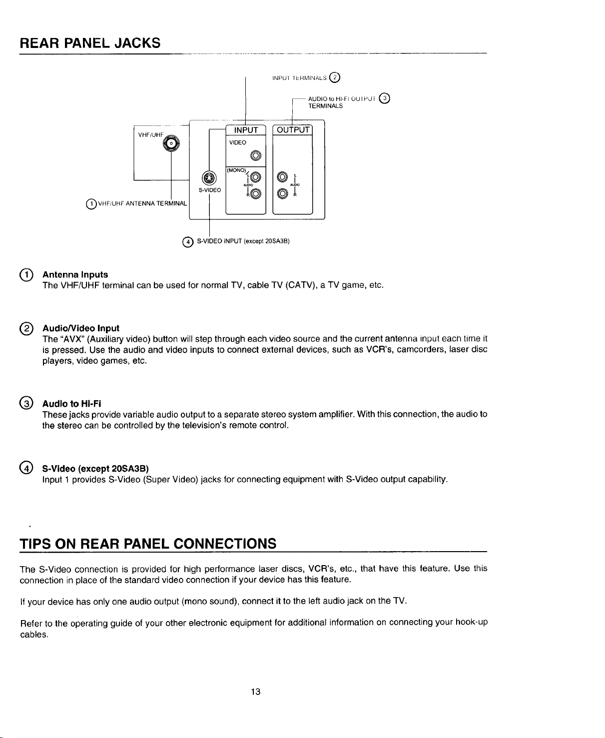
REAR PANEL JACKS
INPUI 1t-RMINALS Q
AUDIO to HI-F10U I P,J i _,_J
TERMINALS
m INp-ifi_5_Q
VIDE(
i
1
©1
i
@
S-VIDEO
Q VHF/UHF ANTENNA TERMINAL
Q S-VIDEO INPUT (except 20SA3B)
Q Antenna Inputs
The VHF/UHF terminal can be used for normal TV, cable TV (CATV), a TV game, etc.
Audio/Video Input
®
The "AVX" (Auxiliary video) button will step through each video source and the current antenna input each time it
is pressed. Use the audio and video inputs to connect external devices, such as VCR's, camcorders, laser disc
players, video games, etc.
Q Audloto HI-Fi
These jacks provide variable audio output to a separate stereo system amplifier. With this connection, the audio to
the stereo can be controlled by the television's remote control.
@
@
(_ S-Video (except 20SA3B)
Input 1 provides S-Video (Super Video) jacks for connecting equipment with S-Video output capability.
TIPS ON REAR PANEL CONNECTIONS
The S-Video connection is provided for high performance laser discs, VCR's, etc., that have this feature. Use this
connection in place of the standard video connection if your device has this feature.
If your device has only one audio output (mono sound), connect it to the left audio jack on the TV.
Refer to the operating guide of your other electronic equipment for additional information on connecting your hook-up
cables.
13
Page 14
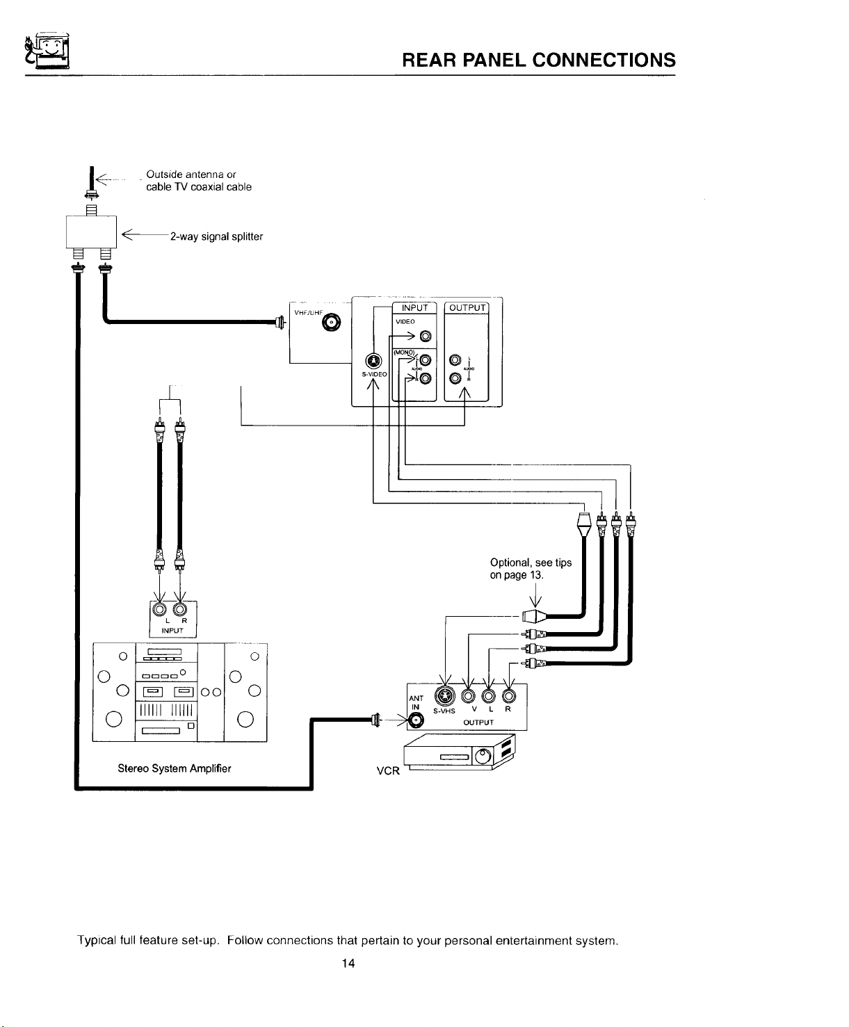
REAR PANEL CONNECTIONS
_.__ Outside antenna or
_ _-_2-way signal splitter
cable TV coaxial cable
Oi
Optional, see tips
on page 13.
V L R
OUTPUT
Stereo System Amplifier
Typical full feature set-up. Follow connections that pertain to your personal entertainment system.
VCR L
14
Page 15
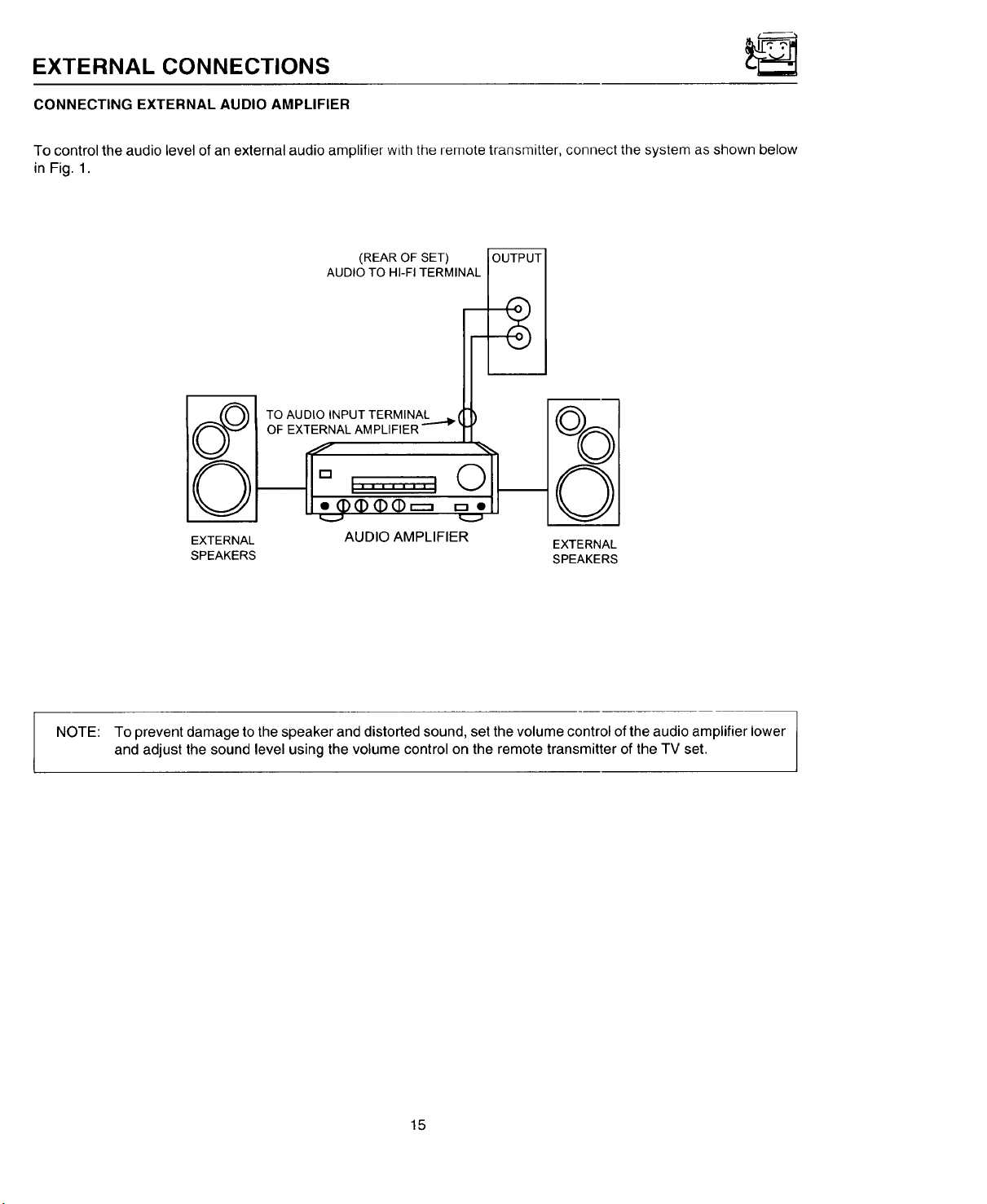
EXTERNAL CONNECTIONS
CONNECTING EXTERNAL AUDIO AMPLIFIER
To control the audio level of an external audio amplifier with the remote transmitter, connect the system as shown below
in Fig. 1.
(REAR OF SET) OUTPUT
AUDIO TO HI-FI TERMINAL
TO AUDtO INPUT TERMINAL k I
OF EXTERNAL AMPLIFIER """_ _
EXTERNAL AUDIO AMPLIFIER
SPEAKERS SPEAKERS
m
_vJ
EXTERNAL
NOTE: To prevent damage to the speaker and distorted sound, set the volume control of the audio amplifier lower
and adjust the sound level using the volume control on the remote transmitter of the TV set.
15
Page 16

CONNECTING EXTERNAL VIDEO SOURCES
The exact arrangement you use to connect the Video Cassette Recorder, Video Disc Player and Video Camera to your
TV set is dependent on the model and features of each component. Check the Owner's Manual of each component for
the location of its video and audio inputs and outputs. The following connection diagrams are offered as suggestions.
However, you may need to modify them to accommodate your particular assortment of components and features. For
best performance, video and audio cables should be made from coaxial shielded wire.
Before Operating External Video Source
The input mode is changed every time the AVX button ispressed as shown below. Connect External source tothe INPUT
terminal, then press the AVX button as necessary to view the input source.
INPUT MODE SELECTION ORDER
(Antenna)
12
_[ VIDEO VIDEO
(Input)
(S-in)
NOTE:
When TV is set to "VIDEO" and a video signal is not received from VIDEO INPUT JACK on the jack panel
of the TV (i.e., VCR/Video Disc Player, etc. is not connected or the video device is OFF), the screen will
be grey-blue.
CONNECTING MONAURAL AUDIO VCR OR VIDEO DISC PLAYER
1. Connect the cable from the VIDEO OUT of the VCR or the Video Disc Player to the INPUT (VIDEO) jack on the TV
set. (Fig. 1)
2. Connect the cable from the AUDIO OUT of the VCR or Video Disc Player to the INPUT (MONO)/L(AUDIO) jack.
(Fig. 1)
3. Press the AVX button to view the program from the VCR or Video Disc Player. The mode "VIDEO" disappears
automatically after approximately 8 seconds.
4. Press the AVX button to return to the previous channel.
5. See Below. Video Cassette Recorder
I _______ur-_, ,|
TV INPUT
'ERMINAL
INPUT
VIDEO
VIDEO OUT AUDIO OUT
_MONO_
@i
AUDIO
FIG. 1
16
Page 17

CONNECTING EXTERNAL VIDEO SOURCES
CONNECTING STEREO VCR OR STEREO VIDEO DISC PLAYER
1.
Connect the cable from the VIDEO OUT of the VCR or the Video Disc Player to the "INPUT (VIDEO)" jack on the
TV set. (Fig. 1)
2.
Connect the cable from the AUDIO OUT "R" of the VCR or the Video Disc Player to the "INPUT(AUDIO/R)" jack.
(Fig. 1)
3.
Connect the cable from the AUDIO OUT "L" of the VCR or the Video Disc Player to the "INPUT(AUDIO/L)" jack.
(Fig. 1)
4. Press the AVX button to view the program from the VCR or Video Disc Player. The mode "VIDEO" disappears
automatically after approximately 8 seconds.
5. Press the AVX button to return to the previous channel.
TVINPUT
TERMINAL
INPUT
Video Cassette Recorder
VIDEO OUT AUDIO OUT
R
I
VIDEO
@®®®
S-VHS V L R
OUTPUT
BACK OF VCR
(MONO_
0"
AUDIO !
i
__2
I
HITACHI MODEL VT-S751A
or similar model
FIG. 1
TV INPUT
TERMINAL
NOTE:
Completely insert the connection cord plugs when connecting to REAR panel jacks. If you do not the
picture that is played back may be abnormal.
If you have an S-VHS VCR, use the S INPUT cable in place of the standard video cable.
17
Page 18

THE REMOTE CONTROL (CLU-415Ul)
In addition to controlling all the functions on your HITACHI Color TV, the new remote is designed to operate different types
of VCR's and CATV (Cable TV) converters with one touch. Basic operation keys are grouped together in one area.
To operate your TV, point the remote at the remote sensor of the TV and press the TV button on the remote. The remote
will now control your TV.
To operate your VCR, point the remote at the remote sensor of the VCR and press the VCR button. The remote will now
control your VCR.
To operate your Cable Box, point the remote at the remote sensor of the Cable Box and press the CABLE button on the
remote. The remote will now control your cable box.
®
RESET SRD TVNCR
®
PIP SWAP SHIFT FRZ
00
These buttons allow the remote to control your TV,
VCR, or Cable Box depending on which mode is
chosen, as explained above.
TV/VCR BUTTON
®
When the remote is in the TV or VCR mode, this is
the TVNCR button. When the remote is in the
CABLE mode, this is the A/B button.
(_ (_LIGHT
CD (Z)
AVX RECALL
0@0
H ITACHI
CLU-415UI
®
®
®,®
PRECODED VCR BUTTONS
These buttons always transmitthe chosen precoded
VCR codes.
RESET BUTTON
Press RESET to return video and audio to factory
settings.
LIGHT BUTTON
When you are in a darkroom, press this button on
thet-,.side of the remote to light up the buttons shown
in (,,_. The light will stay on for about 8 seconds if
the light button is not pressed again. These buttons
will not appear to light if the room is too bright.
J
18
Page 19

THE REMOTE CONTROL (CLU-414Ul)
In addition to controlling all the functions on your HITACHI Color TV, the new remote is designed tooperate different types
of VCR's and CATV (Cable TV) converters with one touch. Basic operation keys are grouped together in one area.
To operate your TV, point the remote at the remote sensor of the TV and press the TV button on the remote. The remote
will now control your TV.
To operate your VCR, point the remote at the remote sensor of the VCR and press the VCR button. The remote will now
control your VCR.
To operate your Cable Box, point the remote at the remote sensor of the Cable Box and press the CABLE button on the
remote. The remote will now control your cable box.
B
®
C)
RESET TVNCR
VCR CONTROL
.Ec _ pausE!
LC.C_
O. _O
@
G) GD
®
®
@
@
®
®
®
®
®,®
These buttons allow the remote to control your TV,
VCR, or Cable Box depending on which mode is
chosen, as explained above.
TV/VCR BUTTON
When the remote is in the TV or VCR mode, this is
the TVNCR button. When the remote is in the
CABLE mode, this is the A/B button.
PRECODED VCR BU'FFONS
These buttons always transmit the chosen precoded
VCR codes.
RESET BUTTON
Press RESET to return video and audio to factory
settings.
LIGHT BUTTON
When you are in a darkroom, press this button on
the side of the remote to light up the buttons shown
in
('_). The light will stay on for about 8 seconds if
the light button is not pressed again. These buttons
will not appear to light if the room is too bright.
(2D (D (D
AVX RECALL
0@0
HITACHI
CLU-414UI
J
19
Page 20

THE REMOTE CONTROL (CLU-412U)
Inaddition to controlling all the functions on you r HITACHI Color TV, the new remote is designed to operate different types
of VCR's and CATV (Cable TV) converters with one touch. Basic operation keys are grouped together in one area.
To operate your TV, point the remote at the remote sensor of the TV and press the TV button on the remote. The remote
will now control your TV.
To operate your VCR, point the remote at the remote sensor of the VCR and press the VCR button. The remote will now
control your VCR.
To operate your Cable Box, point the remote at the remote sensor of the Cable Box and press the CABLE button on the
remote. The remote will now control your cable box.
Q
Q
®
These buttons allow the remote to control your TV,
VCR, or Cable Box depending on which mode is
chosen, as explained above.
TV/VCR BUTTON
®
When the remote is in the TV or VCR mode, this is
the TV/VCR button. When the remote is in the
CABLE mode, this is the A/B button.
®
RESET
PIP SWAP SHIFT FRZ
SRD TVNCR
000
. . .
MUTE
LsT.cH0
O
CD CD
CD (Z) (Z)
AVX RECALL
O@O
HITACHI
CLU-412U
®
PRECODED VCR BUTTONS
®
These buttonsalways transmit the chosen precoded
VCR codes.
RESET BUTTON
®
Press RESET to return video and audio to factory
settings.
J
20
Page 21

HOW TO USE THE REMOTE TO CONTROL YOUR TV
A detailed explanation of the circled numbers is on the following pages. (example: (_).
(_ Q (Z)
RESET TV/VCR
CD CD
VCR CONTROL
(_'11 _ I[_
HITACHI
CLU-415UI
HITACHI
CLU_I4UI
• J
21
@
Page 22

HOW TO USE THE REMOTE TO CONTROL YOUR TV
POWER Button
®
Press this button to turn the -I-Vset on or off. If a message is set, it will be displayed when the TV is first turned on.
(See page 42.)
RECALL Button
®
When you want to check the channel being received, or if it has a stereo (ST) or second audio program (SAP), press
the RECALL button.
You can also check the time, and if the ON TIME or OFF TIME has been set. (See page 41 .)
CHANNEL Channel and
CAPTION_ _/ S Antenna Source
ON TIMER_ .ON 7:00 PM 10:15_ TIME
OFF TIMER"_= j ....... , JlI
AudioSelected
AM _1 '' cast
p.OFF 9:00 =
If a video input is used:
VideoInput
VIDEO
(S-in)
You can also use the RECALL button to quickly clear many of the other On-Screen Displays.
22
Page 23

HOW TO USE THE REMOTE TO CONTROL YOUR TV
MENU, ENTER,
All the on-screen display features can be set or adjusted by using these buttons.
The "MENU" button will start or exit the on-screen display.
The "CURSOR" buttons will highlight functions or adjust different features.
The "ENTER" button will set features to your preference.
Q HANNEL SELECTOR Buttons
Enter two or three numbers to select channels. Enter a "0" first for channels 1 to 9.
For channels over 100, press 1 and wait for 2 seconds before pressing the last two digits of the channel.
Channel selection may also be performed by pressing channel ( _IL ) or down (V).
I NOTE: The TV may not receive some channels if you are not in the correct AIR/CABLE mode. See page 34.
AVX Button
®
The AVX (Auxiliary Video) button will select between the antenna signal and the video input jacks each time the
button is pressed. If the Picture-in-Picture (PinP) is on, the AVX will not select to any source signal. (See page 30.)
Model 27CX25B does not have PINP function.
CURSOR Buttons
ESPN STEREO 28
ST/SA
T
27CX5B, 27CX6B, 27CX25B
AVX
I ESPN STEREO 28
ST/SA
T
AVX
20SA3B
AVX
AVX
VIDEO
AVX
VIDEO
VIDEO
(S-IN)
23
Page 24

HOW TO USE THE REMOTE TO CONTROL YOUR TV
Q VOLUME, MUTE Buttons
Press the "VOLUME" up ( A, ) or down ( V ) button until you obtain the desired sound level.
To turn the sound off instantly to answer the telephone, etc., press the "MUTE" button. Press the "MUTE" button
again or press the "VOLUME" up ( A ) button to restore the sound.
MTV STEREO 28
Louder
fllIIIIIIIIHIHIlUlI"""""""""""""I
The word "MUTE" will remain displayed if the CLOSED CAPTION feature is turned off.
VOLUME
>
The word "MUTE" will not be displayed if the CLOSED CAPTION feature is on.
® LAST CHANNEL (LST-CH) Button
Use this button to select between the last two channels viewed.(Good for watching two sporting events, etc.)
PRME STEREO 28
STtSA
LST-CH
;TEREO 39
©
PICTURE-IN-PICTURE (CLU-414UI does not have a PINP function.)
®
See separate section on page 25 for a description.
LIGHT Button (CLU-412U does not have a light button.)
®
Whenyou are in a dark room, press this button to lightup the volume and _hatlne{bufir0n_. Tt_e(l'gh_wl((s_ayon
for about 8 seconds if no buttons are pressed. The buttons will not appear to light if the room is too bright.
24
Page 25

PICTURE-IN-PICTURE (PIP)
The Picture-in-Picture feature isconvenient when you want to watch more than one plograrn at the same time. You can watch
a TV program while viewing a VCR program (TV or tape) on the video inputs.
Back of TV
VIDEO IN
_ CAI LE /1
OUTPUT @
l÷÷ J ®
Back of VCR
P-IN-P BUTTON
Press the "P IN P" button and sub-picture appears in one corner of the screen. Press the button a second time to
remove the sub-picture from the screen. The TV channel will always be either the main picture or the sub-picture.
Main Picture
NEWS STEREO _ 31
ST/SA
PIP
Sub-Picture
NEWS STEREO
SWAP BUTTON
If you wish to switch what is being shown on the main picture to the sub-picture, press the "SWAP" button.
NEWS STEREO 31
ST/SA
SWAP
I NOTE: Model 27CX25B and 20SA3B do not have P-IN-P function. J
25
I
i
Page 26

PICTURE-IN-PICTURE (PIP)
Q HIFT BUTTON
To move the sub-picture to allother colneJ, press the "SHIFT" button. The sub-picture moves one step
counterclockwise every time the "SHIFT" button is pressed.
SHIFT
0
FREEZE (FRZ) BUTTON
®
Ifyou wish tofreeze the sub-picture, press the"FRZ" button. This is convenient when trying to write down the address
for a mail order company, recording statistics for a sporting event, etc. To return to motion, press the button again.
®
FREEZE (FRZ) BUTTON WITHOUT A SUB-PICTURE (QUICK FREEZE)
Press this button without a sub-picture to freeze the picture you are currently viewing, Press this button again to
return to normal viewing. The SWAP button will not work with this FREEZE function,
31
FRZ
,/_CAUTION: A pattern burn develop if the sub-picture is left in the same corner permanently. If the PIP
1. Only sound from the main picture can be heard.
2. P-IN-P will not work with a CHILD LOCK channel as the main picture but it will be displayed as a Sub-Picture.
I OTE:
3. When the "P-in-P" button is pressed, the sub-picture will appear in the same position as previously set.
feature is used frequently, occasionally shift the sub-picture to a different corner.
may
26
Page 27

USING THE REMOTE TO CONTROL VCR FUNCTIONS
A detailed explanation of the circled numbers is on the following pages. (example: (_).
(z) Q Q- -Q
@-
PIP SWAP SHIFT FRZ.
0000;
@-
Q-.
)o)
G) (D Q - @
OD(D(D
AVX [ RECALL
--O Q O---G
HITACHI
CLU-415UI
r
L
, VCR CONTROL !1
-(9
@
_ :_
-Q
QQQ
OQQ
HITACHI
CLU-4_dUI
L
@
HITACHI
CLU 4_2U
27
Page 28

USING THE REMOTE TO CONTROL VCR FUNCTIONS
Operating the pre-coded function for your VCR
This remote is designed to operate different types of VCR's. You must first program the remote tomatch the remote system
in your VCR. (Refer to page 31 .)
1. Turn on your VCR.
2. Aim the remote control at the front of your VCR.
3. Press the VCR button to switch to the VCR pre-coded mode.
4. While holding down the VCR button, enter the 2 digit preset code that matches your VCR as shown on page 31. The
remote will turn off your VCR when the correct 2 digit preset code is entered. When this occurs, the remote control
is programmed for your VCR. If the VCR does not turn off after 5 seconds, try a different 2 digit preset code.
5. The remote will now control your VCR.
NOTES:
1. If your VCR cannot be operated after performing the above procedures, this means that your VCR's codes have
not been precoded into the remote.
2. In the unlikely event that your VCR cannot be operated after performing the above procedures, consult your VCR
operating guide.
3. The remote control will remember the codes you have programmed in until the batteries are removed from the
remote control. After replacing the batteries repeat the entire programming procedure stated above.
4. If your VCR does not have a power function, the remote will issue the CHANNEL UP function.
VCR BUTTON
®
This allows the remote to control your VCR by setting it to VCR mode.
PRECODED VCR BUTTONS
®
These buttons transmit the chosen precoded VCR codes. For some VCR's, you must press the RECORD button
twice to record a program.
Q EXCLUSIVE TV BUTTONS
These buttons are for operating the TV.
NOTE: Refer to the instruction manual of the VCR for operation of the buttons exclusively for the VCR.
]
28
Page 29

USING THE REMOTE TO CONTROL CABLE BOX FUNCTIONS
A detailed explanation of the circled numbers is on the following pages. (example:(_).
Q-
@-
Q_Q
I RESET 8RD TWVCR
CZD CZ) CZ)-
PiP SWAP SHIFT FRZ
_0000
_] E£I I£D
Q_Q
RESET 7VNCR
Q-
(9-
VCR CONTROL
Q_Q
I_SET SRDI TV,VCR
i_ CZ) CIZ::)-
[O00l PIP SWAP SHIFT
EEl_q _
, Q;) G) CI;)
I
-0 _®;=0_
@-
HITACHI
CLU415UI
-Q
@
-Q
._Q
®
(D (i) Q
QG) Q
._Q
)
;OQQ
I
I(3DQ G)
:g,® ®
--(9
HITACHI
CLU-414Ut
• J _, •
@--
H ITACH I
CLU_i12U
-41)
-Q
-O
29
Page 30

U 51N(3IHI-- HEMOTE TO CONIROL CABLE BOX FUNCTIONS
Operating the pre-coded function for your cable box
This remote isdesigned to operate different types of Cable Boxes. You must firstprogram the remote to match the remote
system in your cable box. (Refer to page 31.)
1. Turn on your cable box.
2. Aim the remote control at the front of your cable box.
3. Press the cable box button to switch to the cable box pre-coded mode.
4. While holding down the CABLE button, enter the 2 digit preset code that matches yourcable box as shown on page
31. The remote will turn off your cable box when the correct 2 digit preset code is entered. When this occurs, the
remote control is programmed for your cable box. If the cable box does not turn off after 5 seconds, try a different
2 digit preset code.
5. The remote will now control your cable box.
NOTES:
1. If your cable box cannot be operated after performing the above procedures, this means that your cable box
codes have not been precoded into the remote.
2. In the unlikely event that your cable box cannot be operated after performing the above procedures, consult your
cable box operating guide.
3. The remote control will remember the codes you have programmed in until the batteries are removed from the
remote control. After replacing the batteries repeat the entire programming procedure stated above.
4. If your cable box does not have a power function, the remote will issue the CHANNEL UP function.
CABLE BUTTON
®
This button allows the remote to control your cable box by setting it to CABLE mode.
PRECODED CABLE BOX BUTTONS
®
These buttons transmit the chosen precoded CATV codes.
TV/VCR BUTTON
@
When the remote is in CABLE mode, this is the A/B button.
ENTER BUTTON
@
If your cable box does not have an enter function, this button will send the TV enter code.
RECALL BUTTON
@
If your cable box does not have a last channel function, this button will send the TV channel recall code.
EXCLUSIVE TV BUTTONS
@
These buttons are for operating the TV.
30
Page 31

VCR AND CABLE BOX CODES
VCR BRAND CODE
Adventura ........................................ 00
Aiko ................................................. 50
Aiwa ................................................ 00
Akai ............................................ 14,23
American High ................................ 09
Asha ................................................. 48
Audiovox ......................................... 10
Beaumark ......................................... 48
Bell & Howell .................................. 30
Brandt .............................................. 38
Broksonic ............................... 33,37,43
Canon ............................................... 09
Carver .............................................. 28
CCE ............................................ 27,50
Citizen .............................................. 50
Colt .................................................. 27
Craig ...................................... 19,27,48
Curtis Mathes ................................... 09
Cybernex .......................................... 48
Daewoo ....................................... 17,50
Dynatech .......................................... 00
Emerex ............................................. 06
Emerson ..................... 00,01,10,16, 23,
.................................... 33,37,40,43
Fisher .......................................... 19,30
Fuji .............................................. 07,09
Funai ................................................ 00
Garrard ............................................. 00
GE ......................................... 09,22,24
Goldstar ...................................... 10,11
Gradiente ......................................... 00
Harley Davidson .............................. 00
Harman/Kardon .............................. 11
Harwood .......................................... 27
HI-Q ................................................. 19
Hitachi ................................... 00,15,24
Jensen .............................................. 14
JVC ............................................. 14,26
Kenwood ........................... 11,14,18,26
KLH ................................................. 27
Kodak .............................................. 09
Lloyd ................................................ 00
Logik ................................................ 27
LXI .................................................. 10
Magnavox .............................. 09,12,28
Magnin ............................................. 48
Marantz .................................. 09,11,28
Marta ................................................ 10
Matsushita ........................................ 09
ME| .................................................. 09
Memorex .................... 00, 09,10,12,18,
.................................... 19,20,30,48
MGA ........................................... 16,23
MGN Technology ............... 48
Minolta ............................................ 15
Mitsubishi ......................... 16,23,26,45
VCR BRAND CODE
Motorola ...................................... 09,20
MTC ............................................ 00,48
Multitech ...................................... 00,27
NEC ................................... l 1,13,14,26
Nikko ................................................ 10
Noblex .............................................. 48
Olympus ........................................... 09
Optimus ............................................ 20
Panasonic ................................ 09,35,46
Penney .................... 09,10,11,13, 15,48
Pentax .......................................... 15,24
Philco ................................................ 09
Philips .......................................... 09,28
Pilot ................................................... 10
Pioneer .............................................. 26
Protec ................................................ 27
Pulsar ................................................ 12
Quartz ............................................... 18
Quasar ............................................... 09
Radio Shack ................................. 00,10
RCA ........................................ 15,22,24
Realistic ........ 00,09,10,18, 19,20,30,48
Ricoh ................................................. 08
Runco ................................................ 12
Samsung ...................................... 17,48
Sanky ........................................... 12,20
Sansui .......................................... 14,26
Sanyo ................................. 18,19,30,48
Scott ........................ 16,17,33,37, 42,43
Sears ....................... 09,10,15,18, 19,31
Sharp ................................................. 20
Shintom ............................................. 27
Shogun .............................................. 48
Singer ................................................ 27
Sony ................................... 06,07,08,09
STS ................................................... 15
Sylvania ............................. 00,09,16,28
Symphonic ........................................ 00
Tatung ............................................... 14
Teac ............................................. 00,14
Technics ....................................... 09,35
Teknika ................................... 00,09,10
TMK ............................................ 40,48
Toshiba ................................... 16,17,44
Totevision .................................... 10,48
Unitech ............................................. 48
Vector ............................................... 17
Vector Research ........................... 11,13
Video Concepts ...................... 13,17,23
Videosonic ........................................ 48
Wards ................. 00,09,15,19, 20,27,48
XR- 1000 ........................................... 27
XRI000 ........................................ 00,09
Yamaha ........................................ 11,14
Zenith ...................................... 07,08,12
31
CAIH.E ItRAND CODE
ABC ......................... 03,05,09,11,12,14
Archer ............................................... 40
Belcor ............................................... 31
Cable Star ......................................... 31
Century ............................................. 40
Citizen ............................................... 40
Contec ............................................... 15
Garrard .............................................. 40
GC Electronics .................................. 31
Gemini .............................................. 13
General Instrument ........................... 09
Hamlin ............................... 08,16,49,50
Hitachi .............................................. 09
Hytex ................................................ 05
Jasco ................................................. 40
Jerrold ........................... 03,09,10,12,13
Memorex ........................................... 00
Movie Time ...................................... 42
NSC .................................................. 42
Oak ......................................... 05,15,47
Panasonic .......................................... 17
Paragon ............................................. 00
Philips ............................................... 40
Pioneer .............................................. 39
Pulsar ................................................ 00
RCA .................................................. 17
Regal ....................................... 16,49,50
Rembrant .......................................... 09
Runco ................................................ 00
Samsung ........................................... 39
Scientific Atlanta ............... 04,06,14,52
Signal ................................................ 13
Signature ........................................... 09
Sprucer .............................................. 17
Standard Components ....................... 41
Starcom ........................................ 03,13
Stargate ............................................. 13
Starquest ........................................... 13
Tocom ..................................... 10,11,33
Page 32

EASY GRAPHIC GUIDE
Press MENU on the remote control to display the different features on your HITACHI TV. The feature to be selected
will be highlighted in a magenta (purple) color.
Press the CURSOR buttons to highlight a different feature.
Press ENTER on the remote control to select a feature.
CURSOR
®® [D B
VIDEO
This part of the screen shows
what selections are available.
>
This part of the screen shows which
remote control buttons to use.
RESET
_eoeeooeoeeoeooeoooeoooeooooooooeeooeooeooeooo
4&_ ENTER MENU
)
• (SET) (EXIT)
CLOCK
D
J 000000 1
AUDIO
32
Page 33

EASY GRAPHIC GUIDE
RESET
PROGRAM
AIR or cable TV. PROGRAM forchannel buttons.
I CHANNEL I Channel butt°ns'cLOSEDaddor erase. CAPTION I Feature t° display
I MEMORY dialogue/text.
I MENU LANGUAGE
Choose English, French, or Spanish Language.
Return video and audio adjustments to factory settings.
ICHANNEL I Label channels ICHILD Block channel
CAPTION PAY1, ABC, etc. LOCK picture & sound.
I PROGRAM I Check channel VOLUME Lower volume on
LIST I name, scan, CORRECTION selected channels.
iSe'eo'aotennaI.UTOIF'rsttimesetu0
childlock.
CLOCK
VIDEO
AUDIO
Turn TV on or off
I CLOCK I Set before using ON/OFF
SET timer features. TIMER
I MESSAGE
Set for one time or daily.
Adjust Contrast, Color, Tint, Brightness, Sharpness and White Control.
IPREFERENCE I Adjust balance, IPREFERENCE I Impr°ve s°und
ADJUST bass, and treble. _SETTING performance.
one time or daily.
33
Page 34

SET UP
Select SE[ UP when setting your TV up for the first time. Use the CURSOR UP/DOWN buttons
on the remote to highlight the function desired.
CURSOR
I MENULANGUAGEI
I AIR/CABLE
AIR
ENTER MENU
(SET) (EXIT)
I Select AIR if you are using an indoor or outdoor antenna. Select CATV if you have cable TV.
,_ ENTER MENU
Press the CURSOR buttons to highlight the correct AIR/
CABLE mode and press MENU to exit.
Your choice will be shown on the display.
RECEPTION BAND
AIR
VHF 2- 13ch
UHF 14 ~ 69ch
CATV 1 or CATV 2
CATV CHANNEL
VHF 2 - 13
Mid band A ~ I
A-5 - A-1
Super band J ~ W
Hyper band
W+l -W+28
Ultra band
W+29-W+84
Indicated
on the screen
2-13
14 - 22
95 - 99
23 - 36
37 - 64
65 ~ 125
CURSOR
(SET) (EXIT)
Your selection
is shown here
.:_IR/CABLE I AUTO
[ MENU LANGUAGE ]
• • (EXIT)
AIR I PROGRAM
CHANNEL
MEMORy
<_• ENTER MENU
(SET) (EXIT)
Reception channels for each mode are shown at
the left.
Refer to your cable or TV guide for channel iden-
tification standards.
If certain CATV channels are poor or not possible
in the CATV1 mode, set AIR/CABLE to CATV2.
AIR/CABLE
[_Z]AIR E]CATVl [_CATV2
MENU
This feature will automatically store active TV channels in CHANNEL MEMORY. This will allow you
I AUTOPROGRAM
IAI_CABLE II_UTO I
ICHANNEL [ICLOSED I
I MENULANGUAGE__
dab ENTER MENU
_- (SET) (EXIT)
to skip over unused channels when using the CHANNEL UP ( A ) or DOWN (V ) buttons.
CURSOR
AUTOPROGRAM
PRESSENTERTOBEGIN
ENTER MENU
(SET) (EXIT)
CHANNEL 05
NOW AUTOPROGRAM
ISIN PROGRESS
¢
If the MENU button is pressed while the auto programming function is engaged, programming will stop.
See CHANNEL MEMORY to add or erase additional channels.
34
IAfler
Operation
Page 35

SET UP
CHANNEL
MEMORY
Use this function after AUTOPROGRAM to add or erase additional channels to the remote control
CHANNEL A, V buttons. Your choice will be highlighted in yellow.
AUTO
PROGRAM
CLOSED
CAPT ON
I MENU LANGUAGE I
,_ ENTER MENU
• (SET) (EXIT)
CURSOR
CHANNEL MEMORY RS
CHANNEL 05
r-,,_ AD g E] ERASE
NEXT CHANNEL: CH& CHV
4 • (EXIT)
MENU
CHANNEL MEMORY
CHANNEL 05
[_ADD FT]ERAS E
NEXTCHANNEL: OH& CHV
'
4 • (EXIT)
MENU
Add or erase additional channels while still in CHANNEL MEMORY using the CHANNEL A, V buttons or number
buttons and then add or erase using the CURSOR _, _ buttons.
I CLOSEDCAPTION I Closed captions are the dialogue, narration, and/or sound effects of a television program or home
video which are displayed on the TV screen. Your local TV program guide denotes these programs
as _ orQ.
AUTO
PROGRAM
CHANNEL
MEMORY
I MENU LANGUAGE I
¢1_ ENTER MENU
(SET) (EXIT)
CURSOR
CLOSED CAPTION
--*DIsP_Y :1710NE]OFF
MODE : r_C.C.[_ TEXT
CHANNEL : r-,7] 1 F_2
_1_ MENU
(EXIT)
The selected function will be magenta. Your choice for the function will be blue.
DISPLAY: ON/OFF is to turn the _ display on or off.
MODE: C.C. (Closed Caption) is for the program you are viewing.
MODE: TEXT isfor additional information such as news reports or aTV program guide. This information covers the entire
screen and viewing the TV program is not possible. TEXT may not be available with every _ program.
CHANNEL: 1 is used for the primary language (usually English).
CHANNEL: 2 is sometimes used for a second language (may vary by region).
Use the CURSOR ,A, or V to highlight the function to change, press ENTER to change the function, and press MENU
to exit.
t_eather Today
unny 70 ° . :
['_eather Tomorrow
|A bit cooler 3°
t iWind Chill -55 °
C.C. Selected Text Selected
DISPLAY in ON. Ifyou do not have sound, make sure MUTE I
NOTE:
The word MUTE
will not be
displayed
if the
is not set.
35
I
Page 36

SET UP
MENU
LANGUAGE J This feature will allow you to select any one of 3 different languages for all on screen displays.
F_-c_l AUFA_O- I
AIR / I PROGRAM I
_1 CLOSED I
J_ r_'I_IENU LANGUAGE ...... J
,_ ENTER MENU
ICAPTION I
(SET) (EXIT)
CURSOR
MENU LANGUAGE
[] ENGLISH
[] FRENCH
[] SPANISH
• MENU
V (EXIT)
Use the cursor _k,, _V' buttons to select the MENU LANGUAGE of your choice.
Press MENU to exit.
_]
MENULANGUAGE
[] ENGLISH
[] FRENCH
[] SPANISH
MENU
(EXIT)
36
Page 37

SET UP
RESET Use the reset to change your preferred video and audio adjustments to factory settings.
ouRso, i cu.soR I PRE_s_i_'_'_R_ '.1
ir'"_']l q FAcToRYsETrli_GS _!i_l--P_ -'J
F_D, ENT F--._i MENU | i ;; ::ENTE_MENU
/ "V (,SET) -,_t" {EX!I"),4 / _.(sEr.)_:_;,_(EXIT.)_1
Factory Settings:
VIDEO AUDIO
Balance: ,,,,.,.,,.,,i,,,,,,.,....
Contrast: IIIIIIIIIIIIlUlIIIIIIIIIIIIIII Bass: ,.,,,,,.J,.d..,..,...,
Color: ,....,..i..,,.,,,,,,. Treble: ,,,...,...i.,..,.,..,,
Tint: ..............I................ MTS Mode: STEREO
Brightness: ..............I................ Loudness: OFF
Sharpness: ..............i................ Internal Speakers: ON
White Control: COOL
I NOTE: This RESET Selection will not change your preferred adjustments. To change back to your adjustments, I
see VIDEO (page 43) or Audio (page 44).
,_ ENTER_ MENU
(SET)_ (EXIT)
Yourpreferred videoadjustments
are nowset
I
I
37
Page 38

PROGRAM
PROGRAM
CHANNEL
CAPTION
CH''o j
LOCK
PFPR-(_ IVOLUME I
ILIST/ ICORRECTION J
41_1_ ENTER MENU
(SET) (EXIT)
This selection contains advanced features which will make TV viewing easier and more enjoyable.
CURSOR
,_ ENTER MENU
(SET) (EXIT)
CURSOR
CHILD
LOCK 1
IVOLUME ]
ICORRECTION I
ENTER MENU
(SET) (EXIT)
Use this feature to give up to 30 channels a name.
PAY1 41
CHANNEL CAPTION
PAY1 (CANCEL)
NEXT CHANNEL: CH& CH•
,_1_ ENTER MENU
(SET) (EXIT)
CHANNEL CAPTION
.... (CANCEL)
NEXT CHANNEL: CH& CH •
_,1_ MENU
(EXIT)
41
CHANNEL
,_,(_ CURSOR
Press the CURSOR _IL, _r to select letters.
Press the CURSOR _, _, to change position.
Press ENTER to set the CHANNEL CAPTION and it will appear in the top left corner ol the screen.
Press CHANNEL _IL, V or the number buttons to select additional channels for labeling.
Press MENU to exit.
The (*) represents a blank space.
Select CANCEL to erase a CHANNEL CAPTION.
This function allows you to view which channels are labeled CHANNEL CAPTION (NAME), which
r PROGRAMLIST
_. CHILD
_ VOLUME
_I_1)' ENTER MENU
(SET) (EXIT)
have been added to CHANNEL MEMORY (SCAN), and are protected by CHILD LOCK (LOCK).
/ LOCK
CORRECTION
CH NAMESCAN LOCK
01
02 CBS ON
03 VCR ON ON
04 NBC ON --
05 WXYZ ON --
• MENU
• (EXIT)
CURSOR
.-->IT].__)
CH NAMESCAN LOCK
06 JAYB ON --
07 JEKO ON
08 ROLY ON ON
09 TESS ON ON
10
• MENU
• (EXIT)
Press CURSOR AL, V" to review more channels.
Press MENU to EXIT.
38
Page 39

PROGRAM
I CHILDLOCK I This function will block out the picture and sound of the selected channel.
[]
CHANNEL CHILD
Q;APTION LOCK
PROGRAM IVOLUME
1..8T ICORRECTION
,_ ENTER MENU
(SET) (EXIT)
CHILD LOCK
_Z] CHILD LOCK KEY NUMBEF
SET _ CHANGE
KEY NUMBER: 0 - 9
NEXT CHANNEL: CH • CH •
41• MENU
[7
41
(EXIT)
The code to set or cancel CHILD LOCK is a three digit key number. The factory preset key number is 000.
CHILD LOCK
[_1 CHILD LOCK [7 KEY NUMBER
SET _ CHANGE
KEY NUMBER: 0 - 9
NEXT CHANNEL: CH • CH •
_1 • MENU
(EXIT)
41
->QQQ-->
CHILD LOCK
71 CHILD LOCK r-i KEY NUMBER
SET _CHANGE
KEY NUMBER: 0 - 9
NEXT CHANNEL: CH • CH •
000
4 • MENU
41
(EXIT)
The picture and sound will now be blocked out for this channel. Repeat the same steps to cancel the CHILD LOCK.
To change the key number, select key number change. Enter the old number (factory preset 000 for first time use), then
enter a new three digit key number you prefer.
Ifyou forget your key number, use the factory code 777 to erase your key number. This resets the key number back to
the factory preset.
39
Page 40

PROGRAM
VOLUME
CORRECT ON
[ _HANNEL C_HILD --q
Use this function to reduce the volume level of up to four TV channels that sound loud compared
to other TV channels.
18
100%
ICAPTION I IlOCK |
ILIST I _UI_I'_L; I IU_ I
dab, ENTER MENU
"_lr-- (SET} IEXIT)
NEXT CHANNEL: CH • CH •
<_lb ENTER MENU
LEVEL
100%
100%
100%
(SET) (EXIT)
Press the CURSOR A, V' to select one of the four volume corrections.
Use the CHANNEL A, V or number buttons to select a channel.
"_ 100% RS
--> lOOO/o ->
D 1O0%
NEXT CHANNEL: CH • CH •
'_ll_ ENTER MENU
100%
(SET) (EXIT)
-_ 75%
_T C_HA 100%
CHANNEL
r_ LEVEL
100%
100%
NNEL: CH • CH •
ENTER MENU
(SET) (EXIT)
100%
100%
100%
LEVEL
100%
NEXT CHANNEL: CH • CH •
_, ENTER MENU
22
(SET) (EXIT)
22
Press ENTER to set the channel.
Press CURSOR _, _, to adjust volume level.
Press MENU to exit.
NOTE:
1. VOLUME CORRECTION adjustment is for the channel displayed in the top right corner of the screen.
To adjust a different channel, you must select the channel with the channel or number buttons and
press ENTER.
2. If the channel has been corrected before, use the cursor A, V to highlight that channel then use
the cursor _, _. to change the level.
3. To erase a channel from the volume correction, select channel 00 and press ENTER.
4. The volume level will change from 50% to 100% in increments of 5%.
40
Page 41

CLOCK
CLOCK
Use this feature for all time related functions.
D
CLOCK
SET
CURSOR
B
Use the NUMBER buttons and CURSOR _, _ to set the time.
The AM or PM selected will be highlighted in blue.
When you have finished setting the time, press ENTER to start.
I ON/OFF
TIMER
The time must be set before you can use the on/oft timer or automatic message.
CURSOR
(SET) (EXIT)
This function will automatically turn the TV on or off, one time only or everyday.
ITIMER I I
I MESSAGE I _--_'--_
PLREATSESET CLOCK /
d&L ENTER MENU /
"V" (SET) (EXIT) /
CLOCK SET
TIME--:-* 17JAM [_PM
HOUR: 01~12
• _ (EXIT)
MENU
/
I MESSAGE I
ENTER MENU
(SET) (EXIT)
-I=.ON TIME: --:--[_Z]AM_] PM
OFF TIME: - -:- -J-',"_AM[_ PM
ON CHANNEL:
MODE:[2}OFF [_NCE [_DAIL¥
CANCEL
HOUR: 01 - 12
MENU
(EXIT)
CURSOR
ON TIME: 07:00_7]AM[_] PM
OFF TIME: 09:00 [_]AM [] PM
ON CHANNEL: - -
-IbMODE:E]OFF [_ONCE r-,7]DAIL_'
CANCEL
HOUR: 01 ~ 12
,_ ENTER MENU
(START) (EXIT)
The selection to change will be in magenta.
Press the number buttons to select the time the TV will turn on or off. (AM: 1, PM: 2)
Press the CURSOR 4, _' buttons for MODE: ONCE (one time only) or MODE: DAILY (TV will turn on/off at the same
time every day).
Press CHANNEL ,A, V or the NUMBER buttons to set the channel the TV will tune to when it automatically turns on.
Your choice for AM/PM and MODE will appear in blue.
Press ENTER to start.
Select CANCEL and press ENTER to erase times.
NOTE: You can set either on time only, off time only, or both. The mode will be the same for both.
I _ll CAUTION: Donot use you rTV as a deterrent when away from home by using both the ON and OFF TIM ERS.
For safety, the TV should be turned off when you are away from home.
41
Page 42

I AUTOMATICMESSAGE
CLOCK
I h_ _,_u_dyv tu_ctiol_ allows the user to program messages of up to 31 characters in the TV's
memory. The user can program the message to appear every day or one time only.
MESSAGE
s_ELTOCK 1 ON/OFF
'I_,1_ ENTER MENU
T MER I
(SET) (EXIT)
*********************
*********************
[_CANCEL
41_1_ ENTER MENU
(SET) (EXIT)
CURSOR
Use the CURSOR _IL, V to select a letter or other character.
Use the CURSOR '_, _- to change position.
Press ENTER when message is finished.
The asterisk (*) represents a blank space.
Move the CURSOR 4, _' until (CANCEL) is magenta and press ENTER to erase message.
MESSAGE
REMEMBER TO TAKE
DALLY VITAMINS
i--'ICANCEL
"_MODE{:Z]OFF [] ONCE [] DALLY
MESSAGE
REMEMBER TO TAKE
DALLY VITAMINS
TIME:--:-- [] AM [] PM
CURSOR
MESSAGE
DO YOUR HOMEWORK OR
I WILL USE CHILDLOCK
I--ICANCEL
ENTER MENU
(SET) (EXIT)
'I_ ENTER MENU
(SET) (EXIT)
_,1_ MENU
(EXIT)
Use CURSOR _IL, V to choose MODE or TIME.
Use CURSOR 4, _' to set MODE when it is magenta. Your choice will be in blue.
Use the NUMBER buttons to set the time.
Press ENTER to start and MENU to exit.
NOTE:
When the scheduled time for the message arrives, the TV will beep 5 times and the message will be
displayed. If you do not wish to wait for the 5 beeps, press a remote button anytime during the 5 beeps.
The beeping will stop and the message will be displayed.
42
Page 43

VIDEO
Select VIDEO to adJust picture settings, and to mipluw plctunu quality.
VIDEO
CURSOR
41_1> ENTER MENU
(SET) (EXIT)
Use this feature to adjust contast, color, tint, brightness, sharpness, and white control.
"_'CONTRAST lllilllllllllllllllllllllllllll
COLOR lllllllllllllllnllllllllllllll
TINT llllllllllllllJllllllllllllllll
BRIGHT IIIIIIIIIIIIIIIIIIIIIIIIIIIIIII
SHARPNESS llllllllllllllIllllllllllllllll
WHITE
CON]3ROL r_ COOL [-]WARM
RESET
,_1> MENU
(EXIT)
Press the CURSOR buttons to select and make adjustments.
The function to be adjusted will be in magenta.
CONTRAST- Use this function to change the contrast between black and white level in the pnctu_.
COLOR- Use this function to adjust the level of color in the picture.
TINT- Use this function to adjust flesh tones so they appear natural.
BRIGHT- Use this function to adjust overall picture brightness.
SHARPNESS- Use this function to adjust the amount of fine detail in the picture.
WHITE CONTROL- Use this function to adjust the white balance (hue) of the picture to your own color pl ete_e__cu.
When shipped from the factory, this is set to : "COOL". If you prefer a reddish screen, set to "WARM".
RESET- When RESET is selected, press ENTER to return video adjustments to factory preset conditions.
43
Page 44

AUDIO
AUDIO
I PREFERENCE I Use this to set balance, bass, and treble.
ADJUSTMENT
special sound effects.
CURSOR
I1. (SET) (EXIT)
I
ENTER MENU
Select AUDIO to adjust the TV to your preference, to improve the sound quality, and to select
CURSOR
_EN-C_ IPREF ERENCE_
l_,12_J_,_--_---JISETTING I
<IP ENTER MENU
(SET) (EXIT)
_1,OREFERENCEI
JUST I
4:11_ ENTER MENU
(SET) (EXIT)
"e'BALANCE liillilinliillllliill niinill
BASS IIIIIIIIIIIInl IIIIIIIIIIIIIIII
T R E B L E IIIIIIIIIIIIIIIIIIIIIIIIIIIIIII
RESET
MENU
(EXIT)
Press the CURSOR buttons to select and make adjustments, The lunction to be adjusted will be in magenta.
BALANCE-
This function will control the left to right balance of the TV internal speakers, the AUDIO TO HI-FI output,
and the surround speakers.
BASS-
TREBLE-
RESET-
This function controls the low frequency audio to all speakers.
This function controls the high frequency audio to all speakers.
When RESET is selected, press ENTER to return audio adjustments to factory preset conditions.
44
Page 45

AUDIO
SETTING
PREFERENCE
Use the CURSOR A, V to select a function. The function will be in magenta.
Use the CURSOR ,_, _. to change function. Your choice will be in blue.
MTS MODE (Multi-Channel Television Sound) will allow you to select STEREO (a stereo broadcast), SAP (second audio
program) which may be a secondary language, weather report, etc. or MONO (monaural sound) used when receiving a
weak stereo broadcast.
The sources received will be displayed below the channel number. The source you select will be displayed to the left of
the channel number. See example below for each selection when both stereo and second audio are received (monaural
is always received).
conditions.
I se Preference SETTING to improve the sound performance of your TV depending on listening
PREFERENCESETTING
PREFERENCE
ADJUST
ENTER MENU
(SET) (EXIT)
ENTER
-->0_)
MTS: I--,7]STEREO FISAP F-]MONC
LOUDNESS r_ON FIOFF
INT. SPEAKERS[_Z]ON [] OFF
,_ MENU
(EXIT)
STEREO SELECTED SAP SELECTED
STEREO 31
ST/S ST/SA
MONOSELECTED
NEWSt [NEWSSAP31]
LOUDNESS
This function will improve the quality of both low and high frequency sounds when listening at low volume levels.
INT. SPEAKERS
This function is useful if you prefer to use only speakers from a separate stereo system.
45
Page 46

CARE OF YOUR HITACHI COLOR TV AND YOUR
REMOTE CONTROL
DO
Dust the screen and cabinet with a soft cloth.
Clean the screen with a soft cloth moistened in warm water. Dry with a soft cloth. (A mild soap may be used if the
screen is extremely dirty.)
Place your TV and remote control away from extreme heat, humidity and extremely dusty places.
Remove the plug from the wall outlet if your television set will not be used for a long period of time, for instance,
when you go on vacation.
DO NOT
Do not clean your screen or cabinet with strong cleaners, polishes or a chemically treated cloth.
Do not place rubber or vinyl products or cellophane tape on your set.
Do not touch the screen too often.
Do not subject the Remote Control to shocks such as dropping iton the floor, etc. Physical damage to the precision
parts may result.
Avoid placing the Remote Control in a high humidity place or getting it wet. Don't leave it on or near a heater.
Excessive heat or moisture may cause the unit to cease operation.
When the batteries run down, remote control operation will become erratic or possibly stop altogether. Replace
the old batteries with fresh "AA" size batteries.
46
Page 47

RECEPTION PROBLEMS
•
Jt', I
• IGNITION NOISE:
Black spots or horizontal streaks may appear, picture may flutter or drift. Usually
caused by interference from automobile ignition systems, neon lamps, electrical
drills and other electrical appliances.
• GHOSTS:
Ghosts are caused by the television signal following two paths. One is the direct
path and the other is reflected from tall buildings, hills or other objects. Changing
the direction or position of the antenna may improve reception. Ghosting may also
be caused by defects in the antenna system such as unshielded lead or connecting
several sets to the same antenna without using multiple antenna couplers.
• SNOW:
If your receiver is located in the fringe area of a television station where the signal
is weak, your picture may be marred by the appearance of small dots. When the
signal isextremely weak, it may be necessary to install a special antenna to improve
the picture.
• RADIO FREQUENCY INTERFERENCE
The interference produces moving ripples or diagonal streaks, and in some cases,
causes loss of contrast in the picture.
47
Page 48

CHECK HERE BEFORE CALLING FOR SERVICE
SYMPTOMS _
No picture, no sound • •
Sound OK, picture poor : • • •
Picture OK, sound poor
Picture blurred
Lines or streaks in picture
Poor reception on some channels
No color
Poor color
I
48
Page 49

SPECIFICATIONS
Features:
• Superfine Picture Quality
600 Line Horizontal Resolution for 27CX5B, 27CX6B and 27CX25B.
• Dark Tint CPT
• Remote Transmitter
(Controls many VCR and Cable Box brands)
• P-in-P Functions (except 27CX25B and 20SA3B)
• ICONS: Easy Graphics Guide
• Full set of Input Jacks, including S-Video (except 20SA3B)
• Closed Caption Decoder
• Comb Filter, Wide-Band Video-Amp (except 20SA3B)
• MTS (Multi-Channel Television Sound) Stereo Broadcast Reception.
• SES - Spatially Equalized Sound (A-Horn) 27CX6B
The SES system places the speakers inside acoustic chambers. The sound resonates through an acoustically
matched baffle system, and projects through thin grills on either side of the TV screen. This system provides greatly
improved sound quality, and proper sound imaging.
Screen Size:
Inputs:
• Power Input..................................... AC 120V, 60 Hz
• Powerconsumption(opemting)
27CX5B, 27CX6B ....................................... 109W
27CX25B ..................................................... 107W
20SA3B ......................................................... 92W
• Power consumption (maximum)
27CX5B, 27CX6B ....................................... 145W
27CX25B ..................................................... 142W
20SA3B ....................................................... 115W
• Antenna input impedance ............................ 75 Ohm
• Channel coverage ......................................... 181 ch.
VHF-Band .................................................... 2-13
UHF-Band 14-69
CATV Mid Band ...................................... A-5-A-1
Super Band .................................................... J-W
Hyper Band ........................................ W+1-W+28
Ultra Band ........................................ W+29-W+84
27V (27 inches measured diagonally) 27CX5B, 27CX6B, 27CX25B
20V (20 inches measured diagonally) 20SA3B
Dimensions:
27CX5B
20SA3B 270X6B
270X25B
• Height (in.)... 177/8 23'/32
• Width (in.)... 20'/4 271/4
• Depth (in.)... 183/4 203/16
• Weight (Ibs.)... 46 88
NOTE: Due to improvements, specifications in this
operating guide are subject to change without notice.
A-1
• Video .............................................. 1.0Vp-p, 75 Ohm
• S-Video
Luminance (Y) ........................... 1.0Vp-p, 75 Ohm
Chrominance (C) ................... 0.286Vp-p, 75 Ohm
• Audio input impedance ............................... 47k Ohm
• Average input level .................................. 470mVrms
• Maximum input level ................................ 940mVrms
49
Page 50

HITACHI
To locate an authorized
HITACHI service facility
in the continental U.S.A.
DIAL TOLL FREE
7 days a week, 24 hours a day
1-800-448-2244
Hitachi Home Electronics (America), Inc.
Hitachi has made every effort to assure you hours of trouble free operation from your unit. However, should you
require service, a network of Hitachi Authorized Service Facilities has been established in all 50 states and Puerto
Rico. Each facility will provide you with convenient and expedient assistance. Our service "Hotline" operator will
direct you to the Hitachi Authorized Service Facility nearest you. Just present proof of purchase and/or delivery
receipts to the Hitachi Authorized Service Facility, and service will be rendered in accordance with the terms of the
limited warranty as stated on your warranty card or operating guide.
Should you have any questions regarding in-warranty service, operation or technical assistance,
please contact:
Hitachi Home Electronics(America), Inc
3890 Steve ReynoldsBlvd
Norcross,GA30093
Tel: 404-279-5600
Hitachi Sales Corporation of Hawaii
3219 Koapaka St.
Honolulu, HI 96819
Tel:808-836-3621
50
Page 51

NOTES
51
Page 52

QR02351
HITACHI
 Loading...