

Page 1
Hard Disk Drive Specification
Ultrastar 15K450
3.5 inch 4Gb FC-AL Hard Disk Drive
Models: HUS154545VLF400
HUS154530VLF400
Version 1.2 29 October 2008
Warning: Printed copies of this document are considered current only on the date of print. Replacement and disposal
of down-level versions is the responsibility of the document holder.
Hitachi Ultrastar 15K450 (FC-AL) Hard Disk Drive Specification
Page 2

3rd Edition (Rev. 1.2) (29 October 2008)
The following paragraph does not apply to the United Kingdom or any country where such provisions are inconsistent
with local law: HITACHI GLOBAL STORAGE TECHNOLOGIES PROVIDES THIS PUBLICATION "AS IS"
WITHOUT WARRANTY OF ANY KIND, EITHER EXPRES S OR IMPLIED, INCLUDING, BUT NOT LIMITED
TO, THE IMPLIED WARRANTIES OF MERCHANTABILITY OR FITNESS FOR A PARTICULAR PURPOSE.
Some states do not allow disclaimer or express or implied warranties in certain transactions, therefore, this statement
may not apply to you.
This publication could include technical inaccuracies or typographical errors. Changes are periodically made to the information herein; these changes will be incorporated in new editions of the publication. Hitachi may make improvements or changes
in any products or programs described in this publication at any time.
It is possible that this publication may contain reference to, or information about, Hitachi products (machines and programs),
programming, or services that are not announced in your country. Such references or information must not be construed to
mean that Hitachi intends to announce such Hitachi products, programming, or services in your country.
T echnical information about this product is available by contacting your local Hitachi Global Storage Technologies representative or on the Internet at http://www.hitachigst.com
Hitachi Global Storage Technologies may have patents or pending patent applications covering subject matter in this document. The furnishing of this document does not give you any license to these patents.
©Copyright Hitachi Global Storage Technologies
Note to U.S. Government Users —Documentation related to restricted rights —U se, dup lication or disclosure is subject to
restrictions set forth in GSA ADP Schedule Contract with Hitachi Global Storage Technologies.
Hitachi Ultrastar 15K450 (FC-AL) Hard Disk Drive Specification
Page 3

Table of Contents
1.0 General............................................................................................................................1
1.1 Introduction................................................................................................................1
1.2 Glossary .....................................................................................................................1
1.3 Caution.......................................................................................................................1
2.0 Outline of the Drive .......................................................................................................3
3.0 Fixed-disk Subsystem Description ...............................................................................5
3.1 Control Electronics ....................................................................................................5
3.2 Head Disk Assembly .................................................................................................5
3.3 Actuator .....................................................................................................................5
4.0 Drive Characteristics.....................................................................................................7
4.1 Formatted Capacity....................................................................................................7
4.2 Data Sheet..................................................................................................................7
4.3 Inquiry Information....................................................................................................8
4.3.1 Product ID.........................................................................................................8
4.3.2 World Wide ID - Block Assignment ................................................................8
4.4 Cylinder allocation.....................................................................................................9
4.5 Performance characteristics.......................................................................................10
4.5.1 Mechanical positioning.....................................................................................11
4.5.2 Drive ready time ...............................................................................................13
4.5.3 Spindle stop time ..............................................................................................13
4.5.4 Data transfer speed............................................................................................13
4.5.5 Buffering operation (read ahead/write cache)...................................................14
5.0 Data Integrity.................................................................................................................15
5.1 Equipment Status.......................................................................................................15
5.2 Error Recovery Procedure..........................................................................................15
6.0 Physical Format .............................................................................................................17
6.1 Shipped Format (P-List) ............................................................................................17
6.2 Reassigned Format (G-List).......................................................................................17
7.0 Electrical Interface.........................................................................................................19
7.1 FC-AL Connector ......................................................................................................19
7.1.1 40 pin SCA-2 SFF-8045 FC-AL Connector Definition....................................19
7.1.2 Voltage and Ground Signals.............................................................................20
7.1.3 Fault LED Out ..................................................................................................20
7.1.4 Ready LED Out ................................................................................................20
7.1.5 Start Mated Controls.........................................................................................21
7.1.6 SEL_n and Enclosure Service Signals..............................................................21
7.1.7 –ENBL_BYP CH1, -ENBL_BYP_CH2..........................................................23
7.1.8 –Drive Present..................................................................................................23
7.1.9 Dev_Ctrl_Code_x.............................................................................................23
8.0 Environment...................................................................................................................25
8.1 Temperature and humidity.........................................................................................25
8.2 Storage requirements .................................................................................................26
Hitachi Ultrastar 15K450 (FC-AL) Hard Disk Drive Specification
Page 4

8.2.1 Packaging..........................................................................................................26
8.2.2 Storage time......................................................................................................26
8.3 Corrosion test.............................................................................................................26
8.4 Cooling requirements.................................................................................................27
9.0 DC Power Requirements...............................................................................................29
9.1 Power Supply Current, Average and Peak.................................................................30
9.2 Ripple Voltage...........................................................................................................32
9.3 Power Consumption Efficiency Index.......................................................................32
10.0 Reliability......................................................................................................................33
10.1 Start/Stop Cycles......................................................................................................33
10.2 Data Reliability........................................................................................................33
10.3 Seek errors ...............................................................................................................33
10.4 Failure prediction (PFA/S.M.A.R.T).......................................................................33
10.5 Preventive Maintenance...........................................................................................33
10.6 Temperature Warning..............................................................................................33
11.0 Mechanical Specifications..........................................................................................35
11.1 Outline .....................................................................................................................35
11.2 Mechanical Dimensions...........................................................................................35
11.3 Interface Connector..................................................................................................37
11.4 Mounting Positions and Tappings ...........................................................................38
11.5 Drive Mounting........................................................................................................40
11.6 Heads Unload and Actuator Lock............................................................................40
12.0 Vibration and Shock....................................................................................................41
12.1 Operating Vibration.................................................................................................41
12.1.1 Random Vibration...........................................................................................41
12.1.2 Swept Sine Vibration.....................................................................................41
12.2 Non-operating Vibrations ........................................................................................41
12.2.1 Random Vibration..........................................................................................41
12.2.2 Swept Sine Vibration.....................................................................................41
12.3 Operating shock......................................................................................................41
12.4 Non-operating shock...............................................................................................42
12.4.1 Half sinewave shock pulse..............................................................................42
12.4.2 Rotational shock ............................................................................................42
13.0 Acoustics.......................................................................................................................43
13.1 Sound power levels..................................................................................................43
14.0 Identification ................................................................................................................45
14.1 Labels.......................................................................................................................45
15.0 Electromagnetic Compatibility...................................................................................47
15.1 Class A Regulatory Notices.....................................................................................48
16.0 Standards......................................................................................................................51
16.1 UL and C-UL Standard Conformity........................................................................51
16.2 European Standards Compliance.............................................................................51
16.3 German Safety Mark................................................................................................51
16.4 Flammability............................................................................................................51
16.5 Corporate Standards Compliance ............................................................................51
17.0 FC-AL attachment.......................................................................................................53
Hitachi Ultrastar 15K450 (FC-AL) Hard Disk Drive Specification
Page 5

17.1 Fundamentals...........................................................................................................53
17.1.1 Node and Port names......................................................................................54
17.1.2 NL_Port address .............................................................................................54
17.1.3 Primitive signals and sequences .....................................................................55
17.1.4 Frames............................................................................................................56
17.1.5 Sequences........................................................................................................56
17.1.6 Exchanges.......................................................................................................57
17.2 Basic Link Services .................................................................................................57
17.2.1 Abort sequence (ABTS).................................................................................57
17.2.2 Basic accept (BA_ACC).................................................................................58
17.2.3 Basic reject (BA_RJT)....................................................................................59
17.3 Extended Link Services ...........................................................................................60
17.3.1 Link Service Accept (LS_ACC)....................................................................61
17.3.2 Link Service Reject (LS_RJT).......................................................................62
17.3.3 Port Login (PLOGI).......................................................................................63
17.3.4 Logout (LOGO).............................................................................................71
17.3.5 Fabric Login (FLOGI) ...................................................................................72
17.3.6 Fabric Address Notification (FAN)...............................................................76
17.3.7 Port Discovery (PDISC) ................................................................................77
17.3.8 Address Discovery (ADISC) .........................................................................77
17.3.9 Process Login (PRLI) ....................................................................................78
17.3.10 Process Logout (PRLO)...............................................................................82
17.3.11 Read Link Error Status Block (RLS)...........................................................84
17.3.12 Report Node Capabilities (RNC).................................................................85
17.3.13 Re-instate Recovery Qualifiers (RRQ)........................................................89
17.3.14 Third Party Process Logout (TPRLO).........................................................90
17.3.15 Request Node Identification Data (RNID) ...................................................92
17.3.16 Report Port Speed Capabilities (RPSC)........................................................95
17.4 Common Fibre Channel Services ............................................................................95
17.4.1 Register FC-4 Types (RFT_ID)......................................................................98
17.5 FC-AL timers...........................................................................................................100
17.5.1 Link Failure.....................................................................................................101
17.6 Invalid frame delimiter ............................................................................................101
18.0 SCSI-FCP .....................................................................................................................103
18.1 Terminology.............................................................................................................103
18.2 Information Units.....................................................................................................104
18.2.1 FCP_CMND ...................................................................................................105
18.2.2 FCP_XFER_RDY...........................................................................................107
18.2.3 FCP_DATA ....................................................................................................107
18.2.4 FCP_RSP ........................................................................................................107
18.3 Task Attributes.........................................................................................................109
18.4 Task Management functions....................................................................................110
18.4.1 Abort Task (Implemented as ABTS BLS).....................................................111
18.4.2 Abort Task Set ................................................................................................111
18.4.3 Terminate Task ...............................................................................................112
18.4.4 Clear ACA ......................................................................................................112
Hitachi Ultrastar 15K450 (FC-AL) Hard Disk Drive Specification
Page 6

18.4.5 Target Reset....................................................................................................112
18.4.6 Clear Task Set.................................................................................................112
18.4.7 Reset LUN ......................................................................................................112
18.5 Miscellaneous ..........................................................................................................112
18.5.1 Tags.................................................................................................................112
18.5.2 Auto-Contingent Allegiance (ACA)...............................................................112
18.5.3 Autosense.......................................................................................................113
19.0 SCSI Command Set ....................................................................................................115
19.1 SCSI Control Byte ...................................................................................................117
19.2 Abbreviations...........................................................................................................117
19.3 Byte ordering conventions.......................................................................................117
19.4 FORMAT UNIT (04)...............................................................................................118
19.4.1 Parameter List Header ....................................................................................120
19.4.2 Defect Descriptor............................................................................................121
19.5 INQUIRY (12).........................................................................................................125
19.5.1 Inquiry Data....................................................................................................126
19.6 LOG SELECT (4C) .................................................................................................137
19.7 LOG SENSE (4D) ...................................................................................................140
19.7.1 Log Page parameters.......................................................................................141
19.7.2 Log Sense Page 0............................................................................................142
19.7.3 Log Sense Page 2............................................................................................143
19.7.4 Log Sense Page 3............................................................................................145
19.7.5 Log Sense Page 5............................................................................................147
19.7.6 Log Sense Page 6............................................................................................149
19.7.7 Log Sense Page D...........................................................................................150
19.7.8 Log Sense Page E ...........................................................................................151
19.7.9 Log Sense Page F............................................................................................152
19.7.10 Log Sense Page 10........................................................................................153
19.7.11 Log Sense Page 15........................................................................................156
19.7.12 Log Sense Page 2F........................................................................................159
19.7.13 Log Sense Page 30........................................................................................160
19.7.14 Log Sense Page 37........................................................................................163
19.8 MODE SELECT (15) ..............................................................................................165
19.9 MODE SELECT (55) ..............................................................................................166
19.10 MODE SENSE (1A)..............................................................................................167
19.10.1 Mode Parameter List.....................................................................................168
19.10.2 Mode Page 00 (Vendor Unique Parameters)................................................172
19.10.3 Mode Page 01 (Read/Write Error Recovery Parameters).............................174
19.10.4 Mode Page 02 (Disconnect/Reconnect Parameters).....................................179
19.10.5 Mode Page 03 (Format Device Parameters).................................................180
19.10.6 Mode Page 04 (Rigid Disk Drive Geometry Parameters) ............................182
19.10.7 Mode Page 07 (Verify Error Recovery Parameters).....................................183
19.10.8 Mode Page 08 (Caching Parameters)............................................................184
19.10.9 Mode Page 0A (Control Mode Page Parameters).........................................186
19.10.10 Control Extension Subpage ........................................................................187
19.10.11 Mode Page 0C (Notch Parameters) ............................................................188
Hitachi Ultrastar 15K450 (FC-AL) Hard Disk Drive Specification
Page 7

19.10.12 Mode Page 19h (Fibre Channel Port Control Page) ...................................190
19.10.13 Mode Page 1A (Power Control) .................................................................192
19.10.14 Mode Page 1C (Informational Exceptions Control)...................................193
19.11 MODE SENSE (5A)..............................................................................................196
19.12 PERSISTENT RESERVE IN (5E)........................................................................197
19.12.1 Service Action...............................................................................................198
19.12.2 Parameter data for Read Keys ......................................................................199
19.12.3 Parameter Data for Read Reservations.........................................................200
19.13 PERSISTENT RESERVE OUT (5F) ....................................................................201
19.13.1 Service Action...............................................................................................202
19.13.2 Type..............................................................................................................203
19.13.3 Parameter list ................................................................................................204
19.13.4 Summary.......................................................................................................205
19.14 PRE-FETCH (34) ..................................................................................................207
19.15 READ (6) - (08).....................................................................................................208
19.16 READ (10) - (28)...................................................................................................209
19.17 READ (12) - (A8)..................................................................................................211
19.18 READ (16) - (88)...................................................................................................212
19.19 READ (32) - (7F/09)..............................................................................................213
19.20 READ BUFFER (3C)............................................................................................215
19.20.1 Combined Header And Data (Mode 00000b)...............................................216
19.20.2 Read Data (Mode 00010b)............................................................................217
19.20.3 Descriptor (Mode 00011b)............................................................................218
19.20.4 Read Data from Echo Buffer (Mode 01010b) ..............................................219
19.20.5 Echo Buffer Descriptor (Mode 01011b).......................................................220
19.20.6 Enable Expander Communications Protocol and Echo Buffer (Mode11010b)..221
19.21 READ CAPACITY (10) - (25)..............................................................................222
19.22 READ CAPACITY (16) (9E/10)...........................................................................224
19.22.1 Returned Data Format...................................................................................225
19.23 READ DEFECT DATA (37).................................................................................226
19.23.1 Defect List Header........................................................................................228
19.23.2 Defect List Descriptor...................................................................................229
19.23.3 Bytes from Index Format (100b) ..................................................................230
19.23.4 Physical Sector Format (101b) .....................................................................231
19.24 READ DEFECT DATA (B7)................................................................................232
19.24.1 Defect List Header........................................................................................233
19.24.2 Defect List Descriptor...................................................................................234
19.24.3 Bytes from Index Format (100b) ..................................................................235
19.24.4 Physical Sector Format (101b) .....................................................................236
19.25 READ LONG (3E) ................................................................................................237
19.26 REASSIGN BLOCKS (07) ...................................................................................238
19.27 RECEIVE DIAGNOSTICS RESULTS (1C) ........................................................240
19.27.1 Receive Diagnostic Results Page 0...............................................................241
19.27.2 Enclosure Service Information (ESI) Page Format ......................................242
19.27.3 Receive Diagnostic Results Page 40.............................................................243
19.27.4 Receive Diagnostic Page A0h.......................................................................245
Hitachi Ultrastar 15K450 (FC-AL) Hard Disk Drive Specification
Page 8

19.28 RELEASE (17) ......................................................................................................246
19.29 RELEASE (57) ......................................................................................................247
19.30 REPORT DEVICE IDENTIFIER (A3/05)............................................................248
19.31 REPORT LUNS (A0)............................................................................................250
19.32 REPORT SUPPORTED OPERATION CODES (A3/0C)....................................251
19.32.1 All_commands parameter data format..........................................................253
19.32.2 One_command parameter data format..........................................................254
19.33 REPORT SUPPORTED TASK MANAGEMENT FUNCTIONS (A3/0D).........255
19.34 REQUEST SENSE (03).........................................................................................257
19.35 RESERVE (16)......................................................................................................258
19.36 RESERVE (56)......................................................................................................259
19.37 REZERO UNIT (01)..............................................................................................260
19.38 SEEK (6) - (0B).....................................................................................................261
19.39 SEEK (10) - (2B)...................................................................................................261
19.40 SEND DIAGNOSTIC (1D)...................................................................................262
19.40.1 Send Diagnostic Page 0 ................................................................................264
19.40.2 Send Diagnostic Page 40 ..............................................................................265
19.40.3 Send Diagnostic Page A0h ...........................................................................267
19.41 SET DEVICE IDENTIFIER (A4/06)....................................................................268
19.42 START STOP UNIT (1B).....................................................................................269
19.43 SYNCHRONIZE CACHE (10) - (35)...................................................................270
19.44 SYNCHRONIZE CACHE (16) - (91)...................................................................271
19.45 TEST UNIT READY (00).....................................................................................272
19.46 VERIFY (2F).........................................................................................................273
19.47 VERIFY (12) - (AF) ..............................................................................................276
19.48 VERIFY (16) - (8F)...............................................................................................277
19.49 VERIFY (32) - (7F/0A).........................................................................................278
19.50 WRITE (6) - (0A) ..................................................................................................280
19.51 WRITE (10) - (2A) ................................................................................................281
19.52 WRITE (12) - (AA) ...............................................................................................284
19.53 WRITE (16) - (8A) ................................................................................................285
19.54 WRITE (32) - (7F/0B)...........................................................................................286
19.55 WRITE AND VERIFY (10) - (2E)........................................................................288
19.56 WRITE AND VERIFY (12) - (AE).......................................................................289
19.57 WRITE AND VERIFY (16) - (8E)........................................................................290
19.58 WRITE AND VERIFY (32) - (7F/0C)..................................................................291
19.59 WRITE BUFFER (3B) ..........................................................................................293
19.59.1 Combined Header And Data (Mode 00000b)...............................................294
19.59.2 Write Data (Mode 00010b)...........................................................................295
19.59.3 Download Microcode (Mode 00100b) .........................................................296
19.59.4 Download Microcode and Save (Mode 00101b) -Single Binary File ..........297
19.59.5 Download Microcode and Save (Mode 00111b) - Multiple Binary Files....298
19.59.6 Write Data to Echo Buffer (Mode 01010b)..................................................299
19.59.7 Enable Expander Communications Protocol (Mode 11010b)......................300
19.60 WRITE LONG (3F)...............................................................................................301
19.61 WRITE SAME (41)...............................................................................................302
Hitachi Ultrastar 15K450 (FC-AL) Hard Disk Drive Specification
Page 9

19.62 WRITE SAME (16) - (93).....................................................................................303
19.63 WRITE SAME (32) - (7F/0D)...............................................................................304
20.0 SCSI Status Byte..........................................................................................................307
21.0 Additional information...............................................................................................309
21.1 Obtaining an AL_PA ...............................................................................................309
21.2 Loop Initialization Procedure ..................................................................................309
21.3 Flow Control............................................................................................................311
21.4 Login Requirements.................................................................................................311
21.5 Public Loop Operation.............................................................................................312
21.5.1 NL_Port Initialization.....................................................................................313
21.6 SCSI Protocol ..........................................................................................................315
21.6.1 Priority of SCSI Status Byte Reporting..........................................................315
21.6.2 Invalid LUN Processing..................................................................................315
21.6.3 Overlapped Commands...................................................................................315
21.6.4 Command Processing During Execution of Active I/O Process ....................316
21.6.5 Unit Attention Condition ................................................................................317
21.6.6 Command Processing During Startup and Format Operations.......................319
21.6.7 Internal Error Condition..................................................................................319
21.6.8 Deferred Error Condition................................................................................319
21.6.9 Degraded Mode...............................................................................................320
21.6.10 Command Processing while Reserved..........................................................327
21.7 Priority Commands..................................................................................................327
21.8 Command Queuing..................................................................................................328
21.8.1 Queue Depth ...................................................................................................328
21.8.2 Queue Full Status............................................................................................328
21.8.3 Effects of LIP on Command Queuing ............................................................328
21.8.4 Termination of I/O Processes .........................................................................328
21.9 Command Reordering..............................................................................................328
21.10 Concurrent I/O Process..........................................................................................328
21.11 Write Cache ...........................................................................................................329
21.12 Automatic Rewrite/Reallocate...............................................................................329
21.13 Segmented Caching ...............................................................................................331
21.13.1 Overview.......................................................................................................331
21.13.2 Read Ahead...................................................................................................331
21.14 Multiple Initiator Systems .....................................................................................331
21.14.1 Sense Data.....................................................................................................331
21.14.2 Mode Pages...................................................................................................331
21.15 Enclosure Services.................................................................................................331
21.15.1 Enclosure Initiated ESI.................................................................................332
21.16 Multiple Initiator Environment..............................................................................332
21.16.1 Initiator Sense Data.......................................................................................332
21.16.2 Initiator Mode Select/Mode Sense Parameters.............................................332
21.17 Reset.......................................................................................................................332
21.17.1 Reset Sources................................................................................................333
21.17.2 Reset Actions................................................................................................333
21.18 Diagnostics.............................................................................................................333
Hitachi Ultrastar 15K450 (FC-AL) Hard Disk Drive Specification
Page 10

21.18.1 Power on Diagnostics ...................................................................................333
21.18.2 Self-test via SEND DIAGNOSTIC Command.............................................334
21.19 Idle Time Function.................................................................................................337
21.20 Command Time out Limits ...................................................................................337
21.20.1 Reassignment Time.......................................................................................337
21.20.2 Format Time .................................................................................................337
21.20.3 Start/Stop Unit Time.....................................................................................337
21.20.4 Medium Access Command Time .................................................................338
21.20.5 Time-out Limits for Other Commands.........................................................338
21.21 Recommended Initiator ERP .................................................................................339
21.21.1 Drive Service Strategy..................................................................................339
21.21.2 Recommendations for System Error Log .....................................................340
21.21.3 Data Recovery Procedure .............................................................................340
21.21.4 Nondata Error Recovery Procedure..............................................................342
22.0 SCSI Sense Data...........................................................................................................349
22.1 SCSI Sense Data Format..........................................................................................349
22.2 Sense Data Description............................................................................................350
22.2.1 Valid (Bit 7 of byte 0).....................................................................................350
22.2.2 Error Code (Bit 6 - 0 of byte 0) ......................................................................350
22.2.3 ILI: Incorrect Length Indicator (Bit 5 of byte 2) ............................................350
22.2.4 Sense Key (Bit 3 - 0 of byte 2) .......................................................................351
22.2.5 Information Bytes (Byte 3 through 6).............................................................352
22.2.6 Additional Sense Length (Byte 7) ..................................................................352
22.2.7 Command Specific Information (Byte 8 through 11).....................................352
22.2.8 Additional Sense Code/Qualifier (Byte 12 and 13)........................................353
22.2.9 RU: Field Replaceable Unit (Byte 14)...........................................................371
22.2.10 Sense Key Specific (Byte 15 through 17).....................................................371
22.2.11 Reserved (Byte 18 through 19).....................................................................374
22.2.12 Vendor unique error information (Byte 20 through 23) ...............................374
22.2.13 Physical Error Record (Byte 24 thru 29) ......................................................374
22.2.14 Reserved (Byte 30 through 31).....................................................................374
23.0 Appendix. UEC list.....................................................................................................375
Hitachi Ultrastar 15K450 (FC-AL) Hard Disk Drive Specification
Page 11

List of Tables
Table 1.Product ID table............................................................................................1
Table 2.Formatted Capacity.......................................................................................7
Table 3.Data Sheet.....................................................................................................7
Table 4.Product ID in Inquiry Command..................................................................8
Table 5.Block assignment of World Wide ID in INQUIRY Command....................8
Table 6.Cylinder allocation........................................................................................9
Table 7.Mechanical positioning performance ...........................................................11
Table 8.Latency time .................................................................................................12
Table 9.Drive ready time ...........................................................................................13
Table 10.Spindle stop time ........................................................................................13
Table 11.Data transfer speed (sector size 512 Byte case)..........................................13
Table 12.Operating and non-operating conditions ....................................................25
Table 13.Maximum allowable surface temperatures.................................................27
Table 14.Input Voltage ..............................................................................................29
Table 15.Power Supply Generated Ripple at Drive Power Connector......................32
Table 16.Power Consumption Efficiency Index........................................................32
Table 17.Physical Dimensions...................................................................................35
Table 18.A-weighted sound power levels..................................................................43
Table 19.IEEE Registered Name format ...................................................................54
Table 20.NL_Port address .........................................................................................54
Table 21.General frame format..................................................................................56
Table 22.Frame header ..............................................................................................56
Table 23.Basic link service command codes.............................................................57
Table 24.BA_ACC Payload.......................................................................................58
Table 25. BA_RJT Payload .......................................................................................59
Table 26.BA_RJT Reason Codes ..............................................................................59
Table 27.BA_RJT Reason Code Explanations..........................................................59
Table 28.Extended Link Service replies....................................................................60
Table 29.Extended Link Service requests..................................................................60
Table 30.Extended Link Service request 11h qualifiers............................................61
Table 31.LS_RJT payload .........................................................................................62
Table 32.LS_RJT reason codes .................................................................................62
Table 33.LS_RJT reason code explanations..............................................................63
Table 34.PLOGI_REQ/PLOGI_ACC payload..........................................................64
Table 35.Common Service Parameter applicability (part 1 of 2)..............................65
Table 36.Common Service Parameter applicability (part 2 of 2)..............................66
Table 37.FC-PH Version ...........................................................................................66
Table 38.Class Service Parameters............................................................................68
Table 39.LOGO payload............................................................................................71
Table 40.LOGO ACC payload ..................................................................................71
Table 41.FLOGI_REQ/FLOGI_ACC payload .........................................................72
Table 42.Common Service Parameters (FLOGI_REQ/FLOGI_ACC).....................73
Table 43.Class Service Parameters............................................................................75
Table 44.FAN payload...............................................................................................76
Hitachi Ultrastar 15K300 (FC-AL) Hard Disk Drive Specification
Page 12

Table 45.ADISC payload...........................................................................................77
Table 46.ADISC ACC payload .................................................................................78
Table 47.PRLI payload..............................................................................................78
Table 48.PRLI ACC payload.....................................................................................79
Table 49.Login Service Parameter page....................................................................79
Table 50.Login Response Service Parameter page....................................................81
Table 51.PRLI/PRLO ACC response codes..............................................................82
Table 52.PRLO payload ............................................................................................82
Table 53.PRLO ACC payload ...................................................................................83
Table 54.Logout Service Parameter page..................................................................83
Table 55.Logout Response Service Parameter page..................................................84
Table 56.RLS payload ...............................................................................................85
Table 57.RLS ACC payload......................................................................................85
Table 58.Link Error Status block...............................................................................85
Table 59.RNC/ACC payload.....................................................................................86
Table 60.RNC Capability Entry.................................................................................87
Table 61.Document Identifiers ..................................................................................88
Table 62.RRQ payload ..............................................................................................89
Table 63.RRQ ACC payload .....................................................................................89
Table 64.TPRLO payload..........................................................................................90
Table 65.TPRLO ACC payload.................................................................................90
Table 66.Logout Service Parameter page..................................................................90
Table 67.Logout Response Service Parameter page..................................................91
Table 68.RNID payload.............................................................................................92
Table 69.RNID accept payload..................................................................................92
Table 70.Common Node Identification Data.............................................................93
Table 71.Topology Discovery Specific Node Identification Data.............................93
Table 72.Topology Discovery Unit Type..................................................................94
Table 73.Topology Discovery Flags..........................................................................95
Table 74.RPSC payload.............................................................................................95
Table 75.RPSC ACC payload....................................................................................95
Table 76.Payload of a CT Header..............................................................................96
Table 77.Command/Response Codes ........................................................................96
Table 78.RFT_ID payload.........................................................................................98
Table 79.RFT_ID ACC/RJT payload........................................................................98
Table 80.FS_RJT Reason Codes ...............................................................................99
Table 81.FS_RJT Reason Explanations.....................................................................99
Table 82.FCAL timer values .....................................................................................100
Table 83.Information Units (IUs)..............................................................................104
Table 84.FCP_CMND payload..................................................................................105
Table 85.FCP_CNTL field ........................................................................................105
Table 86.Task Attribute values..................................................................................105
Table 87.TMF flag values..........................................................................................106
Table 88.FCP_XFER_RDY payload.........................................................................107
Table 89.FCP_RSP payload ......................................................................................107
Table 90.FCP_STATUS field....................................................................................108
Hitachi Ultrastar 15K300 (FC-AL) Hard Disk Drive Specification
Page 13

Table 91.FCP_RSP_INFO field ................................................................................109
Table 92.RSP_CODE definitions ..............................................................................109
Table 93.Task Management function RSP_CODE definitions .................................110
Table 94.SCSI Commands Supported .......................................................................115
Table 95.SCSI Control Byte......................................................................................117
Table 96.FORMAT UNIT (04) .................................................................................118
Table 97.Format of the Parameter List Header..........................................................120
Table 98.Initialization Pattern Descriptor:.................................................................121
Table 99.Defect Descriptor - Block Format (for n + 1 defects) ................................122
Table 100.Defect Descriptor - Bytes From Index Format (for n = 1 defects)...........123
Table 101.Defect Descriptor - Physical Sector Format (for n + 1 defects) ...............124
Table 102.INQUIRY (12)..........................................................................................125
Table 103.Page Code descriptions.............................................................................125
Table 104.Inquiry Data- EVPD = 0...........................................................................126
Table 105.Inquiry Data - EVPD = 1 (Page Code = 00h)...........................................128
Table 106.Inquiry Data - EVPD = 1 (Page Code = 03h)...........................................129
Table 107.Inquiry Data - EVPD = 1 (Page Code = 80h)...........................................131
Table 108.Inquiry Data - EVPD = 1 (Page Code = 83h)...........................................132
Table 109.Inquiry Data - EVPD = 1 (Page Code = D1h)..........................................135
Table 110.Inquiry Data - EVPD = 1 (Page Code = D2h)..........................................136
Table 111.Log Select (4C).........................................................................................137
Table 112.Log Sense (4D).........................................................................................140
Table 113.Log Sense Page 0......................................................................................142
Table 114.Log Sense Page 2 (part 1 of 2)..................................................................143
Table 115.Log Sense Page 2 (part 2 of 2)..................................................................143
Table 116.Log Sense Page 3 (part 1 of 2)..................................................................145
Table 117.Log Sense Page 3 (part 2 of 2)..................................................................145
Table 118.Log Sense Page 5 (part 1 of 2)..................................................................147
Table 119.Log Sense Page 5 (part 2 of 2)..................................................................148
Table 120.Log Sense Page 6......................................................................................149
Table 121.Log Sense Page D.....................................................................................150
Table 122.Log Sense Page E .....................................................................................151
Table 123.Log Sense Page F......................................................................................152
Table 124.Log Sense Page F, Application Client Log ..............................................152
Table 125.Log Sense Page 10....................................................................................153
Table 126.Log Sense Page 10, self-test results..........................................................153
Table 127.Log Sense Page 10, self-test results..........................................................154
Table 128.Log Sense Page 10, Extended Segment Number......................................155
Table 129.Log Sense Page 15....................................................................................156
Table 130. Log Sense Page 2F...................................................................................159
Table 131.Log Sense Page 30....................................................................................160
Table 132.Log Sense Page 37....................................................................................163
Table 133.Mode Select (15).......................................................................................165
Table 134.Mode Select (55).......................................................................................166
Table 135.Mode Sense (1A)......................................................................................167
Table 136.Page Code Usage......................................................................................168
Hitachi Ultrastar 15K300 (FC-AL) Hard Disk Drive Specification
Page 14

Table 137.Mode parameter header (6).......................................................................168
Table 138.Mode parameter header (10).....................................................................169
Table 139.Mode Parameter Block Descriptor ...........................................................170
Table 140.Mode Parameter Page Format ..................................................................171
Table 141.Mode Parameter Page Format ..................................................................171
Table 142.Vendor Unique Parameters - Page 00.......................................................172
Table 143.Mode Page 01 (Vendor Unique Parameters)............................................174
Table 144.Mode Page 02 (Disconnect/Reconnect Parameters).................................179
Table 145.Mode Page 03 (Format Device Parameters).............................................180
Table 146.Mode Page 04 (Rigid Disk Drive Geometry Parameters) ........................182
Table 147.Mode Page 07 (Verify Error Recovery Parameters).................................183
Table 148.Page 08 (Caching Parameters)..................................................................184
Table 149.Page 0A (Control Mode Page Parameters)...............................................186
Table 150.Control Extension Subpage ......................................................................187
Table 151.Page 0C (Notch Parameters).....................................................................188
Table 152.Mode Page 19h .........................................................................................190
Table 153.Values for RR_TOV Units .......................................................................191
Table 154.Page 1A (Power Control)..........................................................................192
Table 155.Page 1C (Informational Exceptions Control) ...........................................193
Table 156.Background Control (Subpage 01h).........................................................195
Table 157.Mode Sense (5A)......................................................................................196
Table 158.Persistent Reserve In (5E) ........................................................................197
Table 159.PERSISTENT RESERVE IN, Service Action Codes..............................198
Table 160.PERSISTENT RESERVE IN, parameter data for Read Keys .................199
Table 161.PERSISTENT RESERVE IN, parameter data for Read Reservations.....200
Table 162.PERSISTENT RESERVE IN, Read Reservation Descriptor...................200
Table 163.PERSISTENT RESERVE OUT (5F).......................................................201
Table 164.PERSISTENT RESERVE OUT, Service Action Code............................202
Table 165.PERSISTENT RESERVE OUT, Type Code ...........................................203
Table 166.Parameter List...........................................................................................204
Table 167.PERSISTENT RESERVE OUT, Service Action, Parameters .................205
Table 168.APTPL and information held by a drive...................................................206
Table 169.PRE-FETCH (34) .....................................................................................207
Table 170.READ (6) - (08)........................................................................................208
Table 171.READ (10) - (28) .....................................................................................209
Table 172.Read (12) - (A8)........................................................................................211
Table 173.READ (16) - (88)......................................................................................212
Table 174.Read (32) - (7F/09)...................................................................................213
Table 175.READ BUFFER (3C)...............................................................................215
Table 176.Read Buffer Header..................................................................................216
Table 177.Read Buffer Description...........................................................................218
Table 178.Echo Buffer Descriptor.............................................................................220
Table 179.READ CAPACITY (10) - (25).................................................................222
Table 180.Format of READ CAPACITY command reply........................................223
Table 181.Read Capcity (16) (9E/10)........................................................................224
Table 182.Returned Data Format...............................................................................225
Hitachi Ultrastar 15K300 (FC-AL) Hard Disk Drive Specification
Page 15

Table 183.READ DEFECT DATA (37)....................................................................226
Table 184.Defect List Format....................................................................................227
Table 185.Defect List Header....................................................................................228
Table 186.Defect List Descriptor...............................................................................229
Table 187.Defect Descriptors of Bytes from Index Format ......................................230
Table 188.Defect Descriptors of Physical Sector Format..........................................231
Table 189.READ DEFECT DATA (B7)...................................................................232
Table 190.Defect List Header....................................................................................233
Table 191.Defect List Descriptor...............................................................................234
Table 192.Defect Descriptors of Bytes from Index Format ......................................235
Table 193.Defect Descriptors of Physical Sector Format..........................................236
Table 194.READ LONG (3E) ...................................................................................237
Table 195.REASSIGN BLOCKS (07) ......................................................................238
Table 196.Format of Reassign Blocks data ...............................................................239
Table 197.RECEIVE DIAGNOSTIC RESULTS (1C) .............................................240
Table 198.Receive Diagnostic Results page 0...........................................................241
Table 199.Enclosure Page Support for Send and Receive Diagnostic Commands...242
Table 200.ESI Page Format.......................................................................................242
Table 201.Receive Diagnostic Results Page 40.........................................................243
Table 202.Translated address ....................................................................................243
Table 203.Device LED Control Page - Receive Diagnostic......................................245
Table 204.RELEASE (17).........................................................................................246
Table 205.RELEASE (57).........................................................................................247
Table 206.REPORT DEVICE IDENTIFIER (A3/05)...............................................248
Table 207.Report Device Identifier parameter list ....................................................249
Table 208.REPORT LUNS (A0)...............................................................................250
Table 209.LUN Reporting parameter list format.......................................................250
Table 210.Report Supported Tasks Management Functions (A3/0D) ......................255
Table 211.REQUEST SENSE (03) ...........................................................................257
Table 212.RESERVE (16).........................................................................................258
Table 213.RESERVE (56).........................................................................................259
Table 214.REZERO UNIT (01).................................................................................260
Table 215.SEEK (6) - (0B)........................................................................................261
Table 216.SEEK (10) - (2B)......................................................................................261
Table 217.SEND DIAGNOSTIC (1D)......................................................................262
Table 218.SEND DIAGNOSTIC Function Code (1D) .............................................263
Table 219.Diagnostic Page 0 .....................................................................................264
Table 220.Diagnostic Page 40 ...................................................................................265
Table 221.Address to translate...................................................................................266
Table 222.Device LED Control Page - Send Diagnostic...........................................267
Table 223.SET DEVICE IDENTIFIER (A4/06).......................................................268
Table 224.SET DEVICE IDENTIFIER, Parameter List...........................................268
Table 225.START STOP UNIT (1B)........................................................................269
Table 226.SYNCHRONIZE CACHE (10) - (35)......................................................270
Table 227.Synchronize Cache (16) - (91)..................................................................271
Table 228.TEST UNIT READY (00)........................................................................272
Hitachi Ultrastar 15K300 (FC-AL) Hard Disk Drive Specification
Page 16

Table 229.VERIFY (2F)............................................................................................273
Table 230.Verify (12) - (AF).....................................................................................276
Table 231.Verify (16) - (8F)......................................................................................277
Table 232.Verify (32) - 7F/0A) .................................................................................278
Table 233.WRITE (6) - (0A).....................................................................................280
Table 234.WRITE (10) - (2A)...................................................................................281
Table 235.Write (12) - (AA)......................................................................................284
Table 236.Write (32) - (7F/0B)..................................................................................286
Table 237.WRITE AND VERIFY (10) - (2E) ..........................................................288
Table 238.Write andVerify (12) - (AE).....................................................................289
Table 239.Write and Verify (16) - (8E).....................................................................290
Table 240.Write and Verify (32) - (7F/0C) ...............................................................291
Table 241.WRITE BUFFER (3B) .............................................................................293
Table 242.Write Buffer Header .................................................................................294
Table 243.WRITE LONG (3F)..................................................................................301
Table 244.WRITE SAME (41)..................................................................................302
Table 245.Write Same (16) - (93)..............................................................................303
Table 246.Write Same (32) - (7F/0D) .......................................................................304
Table 247.SCSI Status Byte. Format of the SCSI STATUS byte. ...........................307
Table 248.LIxx Frame Payloads................................................................................310
Table 249.Response to Frames before PLOGI or PRLI............................................312
Table 250.Spindle Motor Degraded Mode - Disable Auto Start...............................321
Table 251.Spindle Motor Degraded Mode - Auto Start Delay/Spinning Up ............322
Table 252.Spindle Motor Degraded Mode - Spindle Start Failure............................323
Table 253.Spindle Motor Degraded Mode - Spindle Stopped by Unit Stop Command324
Table 254.Self Configuration Failure Degraded Mode ............................................325
Table 255.Format Command Failure Degraded Mode..............................................326
Table 256.Sense data combinations with auto/recommend rewrite/reallocate..........330
Table 257.Short and Extended Self-Test Description ...............................................336
Table 258.Recommend Reassign Errors....................................................................341
Table 259.Log Only Errors........................................................................................341
Table 260.Format of Sense Data................................................................................349
Table 261.Field Pointer Bytes ...................................................................................371
Table 262.Actual Retry Count...................................................................................372
Table 263.Progress Indication ...................................................................................373
Table 264.Unit Error Codes.......................................................................................375
Hitachi Ultrastar 15K300 (FC-AL) Hard Disk Drive Specification
Page 17
1.0 General
1.1 Introduction
This document describes the specifications of the following Hitachi 3.5 inch FC-AL drives.
Table 1: Product ID table
Product ID Description
HUS154545VLF400 450 GB, FC-AL
HUS154530VLF400 300 GB, FC-AL
Note: The specifications in this document are subject to change without notice.
For technical and ordering information, please visit our website at http://www.hitachigst.com.
1.2 Glossary
Word Meaning
BMS Background Media Scan
Kb Kilobit = 1000 bits
Mb Megabit = 1,000,000 bits
GB Gigabyte = 1,000,000,000 bits
HDD Hard Disk Drive
MB Megabyte = 1,000,000 bytes
KB Kilobyte = 1000 bytes
PFA Predictive Failure Analysis
S.M.A.R.T. Self-Monitoring and Reporting Technology
FC-AL Fibre Channel - Arbitrated Loop
1.3 Caution
This drive can be damaged by ESD (Electric Static Discharge). Any damages incurred to the drive after its removal from the
shipping package and the ESD protective bag are the responsibility of the user.
Hitachi Ultrastar 15K450 (FC-AL) Hard Disk Drive Specification
1
Page 18

Hitachi Ultrastar 15K450 (FC-AL) Hard Disk Drive Specification
2
Page 19

2.0 Outline of the Drive
• Storage capacities of 450 GB, 300 GB
• Dual 4.250/2.1250/1.0625 Gb/s Fibre Channel Arbitrated Loop-2 host interfaces
• Supports dual-ported operations
• Supports full duplex operations
• Login BB_Credit=0
• Enclosure Service Interface (ESI, SFF-8045 Rev. 4.2) and Enclosure Initiated ESI (SFF-8067 Rev. 2.6) compliant
• Variable Sector Size (512,520,528 bytes/ sector)
• Tagged Command Queuing support
• Automatic read/write data transfer
• 3.6 ms seek time in read operation for 450 GB
• 3.6 ms seek time in read operation for 300 GB
• Adaptive read ahead algorithm
• Write Cache
• Back to back write
• ECC On The Fly correction
• Automatic defect reallocation
• Self diagnostics at power on
• Closed loop actuator servo
• Non head disk contact start/stop
• 15,000 RPM spindle rotation speed
• Automatic actuator lock
• PFA (S.M.A.R.T.)
• ANSI T10 Protection Information (End-to-End)
Hitachi Ultrastar 15K450 (FC-AL) Hard Disk Drive Specification
3
Page 20

Hitachi Ultrastar 15K450 (FC-AL) Hard Disk Drive Specification
4
Page 21

3.0 Fixed-disk Subsystem Description
3.1 Control Electronics
The drive is electronically controlled by a microprocessor, logic modules, digital/analog modules and various drivers and
receivers. The control electronics perform the following major functions:
• Perform self-checkout (diagnostics)
• Conduct a power-up sequence and calibrate the servo.
• Monitor various timers for head settling, servo failure, etc.
• Analyze servo signals to provide closed-loop control. These include position error signal and estimated veloci ty.
• Control of the voice coil motor driver to align the actuator onto a desired position
• Monitor the actuator position and determine the target track for a seek operation.
• Constantly monitor error conditions of the servo and take corresponding action if an error occurs.
• Control starting, stopping, and rotating speed of the spindle.
• Control and interpretation of all interface signals between the host controller and the drive
• Control of read/write accessing of the disk media, including defect management and error recovery
3.2 Head Disk Assembly
The head/disk assembly (HDA) is assembled in a clean room environment and contains disks, a spindle motor, actuator assembly, and voice coil motor. Air is constantly circulated and filtered when the drive is operational. Venting of the HDA is accomplished via a breather filter.
The spindle is driven directly by a brushless, sensorless DC drive moto r. Dynamic braking is used to stop the spindle quickly.
3.3 Actuator
The read/write heads are mounted in the actuator. The actuator is a swing-arm assembly driven by a voice coil motor. A
closed-loop positioning servo controls the movement of the actuator. An embedded servo data pattern supplies feedback to the
positioning servo to keep the read/write heads centered over the desired track.
The actuator assembly is balanced to allow vertical or horizontal mounting without adjustment.
Heads are moved out from the disks (unloaded) to protect the disk data during shipping, moving, or storage. At power down,
the heads are automatically unloaded from over the disk area and the head actuator locking mechanism will secure the heads in
the unload position.
Hitachi Ultrastar 15K450 (FC-AL) Hard Disk Drive Specification
5
Page 22

Hitachi Ultrastar 15K450 (FC-AL) Hard Disk Drive Specification
6
Page 23
4.0 Drive Characteristics
4.1 Formatted Capacity
Table 2: Formatted Capacity
Description HUS154545VLF400 HUS154530VLF400
Label capacity 450 GB 300 GB
Number of heads 8 8
Number of disks 4 4
Total data bytes (512
bytes/sector)
Total logical data
blocks
450,098,159,616 300,000,000,000
879,097,968
(3465F870h)
585,937,500
(22ECB25Ch)
4.2 Data Sheet
Table 3: Data Sheet
Buffer to/from media 450 GB 1290 - 2120 [Mb/sec]
Buffer to/from media 300 GB 1265 - 1738 [Mb/sec]
Host to / from buffer (interface transfer rate) 106.25 MB/s (1 Gb/s) 212.5 MB/s (2 Gb/s)
425.0MB/s (4Gb/s)
Data buffer size 16MB
Number of buffer segments 1 - 254
Rotational speed 15,000 RPM
Recording density 1138 [Kbpi] (Max)
Track density 150,000 [TPI] (average)
Areal density 183 [Gb/sq. in.]
Data zones 23 Zones for 450 GB, 18 Zones for 300 GB.
Hitachi Ultrastar 15K450 (FC-AL) Hard Disk Drive Specification
7
Page 24
4.3 Inquiry Information
4.3.1 Product ID
Product ID in Section 19.5.1.1, “Inquiry Data Format - EVPD = 0, Page Code = 0” on page 126, is as follows:
Table 4: Product ID in Inquiry Command
Product ID Description
HUS154545VLF400 450 GB, FC-AL
HUS154530VLF400 300 GB, FC-AL
4.3.2 World Wide ID - Block Assignment
Block Assignment of World Wide ID is as follows:
Tabl e 5: Block assignment of World Wide ID in INQUIRY Command
Manufacturing Site Product Block Assignment
HUS154545VLF400
Singapore
Note (1) - Additional block assignment wi ll be issued as needed based on actual production volume.
HUS154530VLF400
001h
001h
(1)
(1)
Hitachi Ultrastar 15K450 (FC-AL) Hard Disk Drive Specification
8
Page 25

4.4 Cylinder allocation
Zone Sectors /Tracks Cylinder/Zo ne
Start
Cylinder
End
Cylinder
0 1416 3600 0 3599
1 1404 3700 3600 7299
2 1395 700 7300 7999
3 1350 26500 8000 34499
4 1296 3900 34500 38399
5 1282 3300 38400 41699
6 1260 6900 41700 48599
7 1242 2100 48600 50699
8 1215 5100 50700 55799
9 1188 2400 55800 58199
10 1170 3200 58200 61399
11 1147 2200 61400 63599
12 1134 2400 63600 65999
13 1125 600 66000 66599
14 1080 8500 66600 75099
15 1026 3400 75100 78499
16 1012 2300 78500 80799
17 990 2900 80800 83699
18 972 1900 83700 85599
19 945 3900 85600 89499
20 918 2300 89500 91799
21 900 2900 91800 94699
22 877 500 94700 95199
User Cy lind e r Allocatio n 450 G B
Table 6: Cylinder allocation
Hitachi Ultrastar 15K450 (FC-AL) Hard Disk Drive Specification
9
Page 26
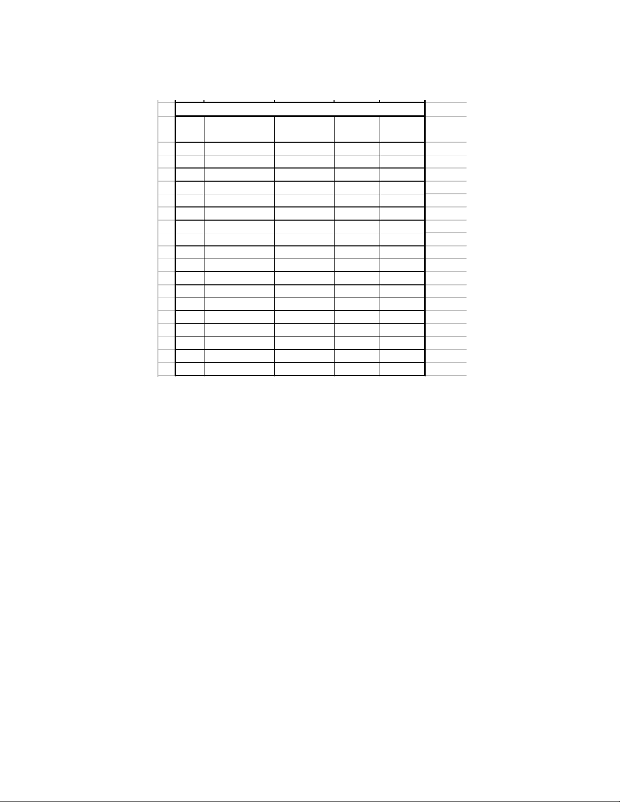
Note: Values shown are nominal. Actual values will vary based on manufacturing optimization. Mode Page 03 (Format
Z o n e Secto rs /Tra cks Cylinder/Zo n e
Start
Cylinder
End
Cylinder
0 1188 5800 0 5799
1 1170 13300 5800 19099
2 1147 6400 19100 254 99
3 1134 3000 25500 284 99
4 1125 1200 28500 296 99
5 1080 13800 29700 43499
6 1041 800 43500 44299
7 1035 1800 44300 46099
8 1026 1900 46100 47999
9 1012 2700 48000 50699
10 1002 600 50700 51299
11 990 3100 51300 54399
12 972 2200 54400 56599
13 945 4600 56600 61199
14 918 2600 61200 63799
15 900 3300 63800 67099
16 877 2500 67100 69599
17 864 200 69600 69799
User Cylinder Alloca tion 300 GB
Device Parameters), page 180 and Mode Page 0C (Notch Parameters), page 188 provide methods to determine actual
medium format and zone parameters for specific drives.
4.5 Performance characteristics
Drive performance is characterized by the following parameters:
•Command overhead
•Mechanical head positioning
- Seek time
•Data transfer speed
•Buffering operation (read ahead/write cache)
Note: All the above parameters contribute to drive performance. There are other parameters that contribute to the performance of the actual system. This specification tries to define the bare drive characteristics, not system throughput, which
depends on the system and the application.
- Latency
Hitachi Ultrastar 15K450 (FC-AL) Hard Disk Drive Specification
10
Page 27
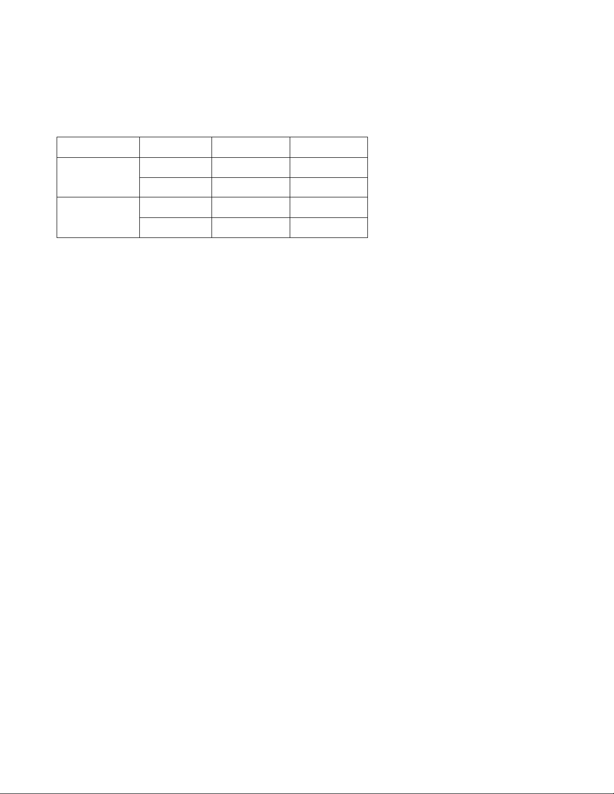
4.5.1 Mechanical positioning
max 1 n–+ ) Tnin Tnout+(⋅()=
n 1=
Max
∑
max 1+()max()⋅
------------------------------------------------------------------------------------------------
4.5.1.1 Average seek time (including settling)
Table 7: Mechanical positioning performance
Model Command Typical (ms) Max
450 GB Read 3.3 5.0
Write 3.8 5.4
300 GB Read 3.1 4.5
Write 3.6 5.1
“Typical” and “Max” are used throughout this document and are defined as follows:
Typical Average of the drive population tested at nominal environmental and volt age conditions.
Max Maximum value measured on any one drive over the full range of the environmental and voltage conditions.
(See Section 8.0, “Environment” on page 25 and Section 9.0, “DC Power Requirements” on page 29 for
ranges.)
Seek time is measured from the start of the actuator’s motion to the start of a read or write operation. Average seek time is
measured as the weighted average of all possible seek combinations.
Weighted average =
Where:
max = Maximum seek length
n= Seek length (1 to max)
Tn.in = Inward measured seek time for an n track seek
Tn.out = Outward measured seek time for an n track seek
Hitachi Ultrastar 15K450 (FC-AL) Hard Disk Drive Specification
11
Page 28
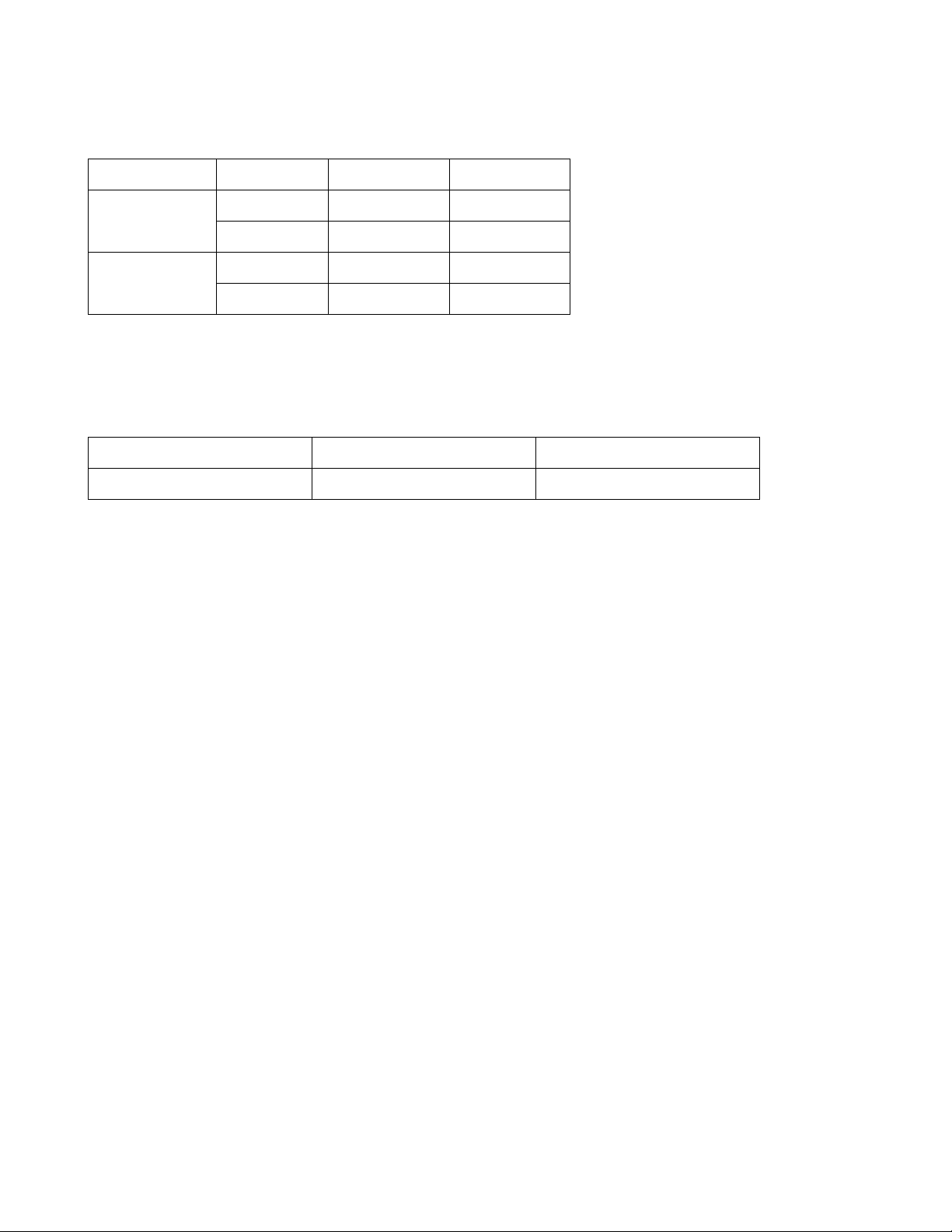
4.5.1.2 Full stroke seek time
Model Command Typical (ms) Max
450 GB Read 6.2 11.1
Write 7.1 11.5
300 GB Read 5.8 9.4
Write 6.4 10.1
Full stroke seek is measured as the average of 1,000 full stroke seeks with a random head switch from both directions (inward
and outward).
4.5.1.3 Average latency
Table 8: Latency time
Rotation Time for a revolution (ms) Average latency (ms)
15,000 RPM 4.0 2.0
Hitachi Ultrastar 15K450 (FC-AL) Hard Disk Drive Specification
12
Page 29
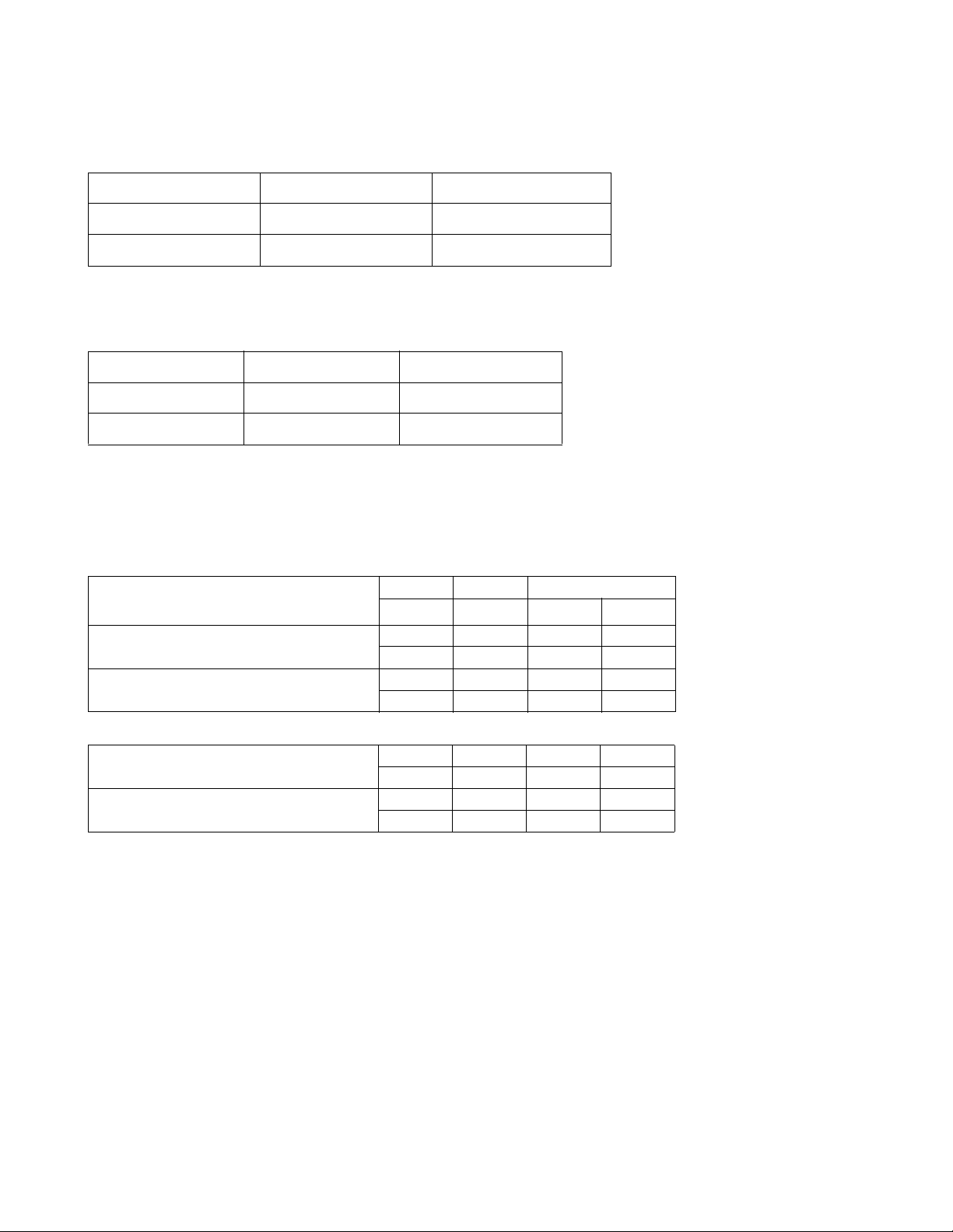
4.5.2 Drive ready time
Table 9: Drive ready time
Model Typical (sec) Maximum (sec)
450 GB Model 21.0 29.9
300 GB Model 21.0 29.9
4.5.3 Spindle stop time
Table 10: Spindle stop time
Model Typical (sec) Maximum (sec)
450 GB Model 11.0 20
300 GB Model 11.0 20
The period from power off to the complete stop of the rotating spindle is categorized as 'operating'. The Operating shock criteria apply during this period. Refer to section 12.3, “Operating shock” on page 41.
4.5.4 Data transfer speed
Table 11: Data transfer speed (sector size 512 Byte case)
Description
Disk-buffer transfer
Instantaneous 0 450 GB 179.7 179.7
Measured typical values for sustained diskbuffer tranfer rate
Instantaneous 22 450 GB 112.3 112.3
Measured typical values for sustained diskbuffer tranfer rate
Notes:
• Instantaneous disk-buffer transfer rate is derived by: (Number of sectors on a track) x 512 x (revolutions/sec)
• For this table, '1 MB / Sec' should be interpreted as 1,000,000 bytes per Second.
• The number of sectors per track will vary by zone because of the linear density recording.
• Sustained disk-buffer transfer rate is the average rate measured while transferring multiple cylinders of data. It differs from the instantaneous transfer rate because of the time required to change tracks (Cylinder skew and Head
skew). In addition, time is added for the occasional missed transfer.
Zone Model Read Write
0 300 GB 152.1 152.1
0 450 GB 160.0 155.8
0 300 GB 135.0 131.5
17 300 GB 110.6 110.6
22 450 GB 99.9 97.3
17 300 GB 98.2 95.6
Typical (MB / Sec)
4.5.5 Buffering operation (read ahead/write cache)
This hard disk drive has a buffer for read ahead (see Segmented Caching, page 331).
Hitachi Ultrastar 15K450 (FC-AL) Hard Disk Drive Specification
13
Page 30

Hitachi Ultrastar 15K450 (FC-AL) Hard Disk Drive Specification
14
Page 31

5.0 Data Integrity
The drive retains recorded information under all non-write operations.
No more than one sector can be lost by power down during a write operation while write cache is disabled. If power down
occurs before completion of a data transfer from write cache to disk while write cache is enabled, the data remaining in the
write cache will be lost. To prevent this data loss at power off, the following action is recommended:
• Confirm successful completion of a SYNCHRONIZE CACHE (35h) command
5.1 Equipment Status
Equipment status is available to the host system any time the drive is not ready to READ, WRITE or SEEK. This status normally exists at power-on time and will be maintained until the following conditions are satisfied:
• Access recalibration/tuning is complete
• Spindle speed meets requirements for reliable operations
• Self-check of drive is complete
Appropriate error status is made available to the host system if any of the following conditions occur after the drive has
become ready:
• Spindle speed goes outside of requirements for reliable operation
• “Write fault” is detected
5.2 Error Recovery Procedure
Errors occurring with the drive are handled by the error recovery procedure.
Errors that are uncorrectable after application of the error recovery procedures are reported to the host system as non-recover-
able errors.
Hitachi Ultrastar 15K450 (FC-AL) Hard Disk Drive Specification
15
Page 32

Hitachi Ultrastar 15K450 (FC-AL) Hard Disk Drive Specification
16
Page 33

6.0 Physical Format
Media defects are remapped to the next available sector during the Format Process in manufacturing. The mapping from Logical Block Address (LBA) to the physical Block locations is calculated using internally maintained tables.
6.1 Shipped Format (P-List)
• Data areas are optimally used.
• All pushes generated by defects are absorbed by available tracks of the inner notch.
P-List Physical Format
Note: Defects are skipped without any constraint, such as track or cylinder boundary. The calculation from LBA to physical
is done automatically by internal table.
6.2 Reassigned Format (G-List)
• G-List has a capacity of 5000 Customer LBAs.
• Multiple reassignments of the same Customer LBA do not increase the number of G-List entries.
• A track for spare sectors is inserted after every 800 nominal customer tracks.
.
Hitachi Ultrastar 15K450 (FC-AL) Hard Disk Drive Specification
17
Page 34

Hitachi Ultrastar 15K450 (FC-AL) Hard Disk Drive Specification
18
Page 35

7.0 Electrical Interface
7.1 FC-AL Connector
The drive conforms to SFF specifications 8045, 8067 and 8451. The SFF 8045/8067 documents defines the electrical specification and SFF-8451 defines the mechanical specification. The only difference between SFF-8045 and SFF-8067 is the
Enclosure Service Interface. The drive will 'discover' the level of Enclosure Service Interface supported by the enclosure, and
use the proper level for enclosure communication. This 'discovery ' process is defin ed in the SFF-8067 specification.
The connector is expected to be used in an environment which uses a common connector structure for racking disk drives in a
cabinet. The connector allows for plugging a drive directly into a backplane by providing th e necessary electrical connection.
Mechanical stability and device retention must be provided by a mechanism outside the drive.
The signals defined in this connector include:
•Dual ported Fibre Channel In/Out control signals
• +5V and +12V power
• ID select
• Motor start control
• LED drive signals
• PBC Interlock control
• Fibre Channel link rate selection/Hard Reset
• Power control
7.1.1 40 pin SCA-2 SFF-8045 FC-AL Connector Definition
The drive uses the connector compatible with the SFF-8045 connector specifications. The connector contact assignment is
shown in following table.
Table 12: 40-pin Connector Signal Definition
Signal Name Pin # Pin # Signal Name
-ENBL BYP CH1 1 21 12V Charge
12 Volts 2 22 12V Ground
12 Volts 3 23 12V Ground
12 Volts 4 24 +Port 1_In
-Parallel ESI 5* 25 -Port 1_In
-Drive Present 6 26 12V Ground
Ready LED Out 7 27 +Port 2_In
Power Control 8 28 -Port 2_In
Start_1/Mated 9 29 12V Ground
Start_2/Mated 10 30 +Port 1_Out
-ENBL BYP CH2 11 31 -Port 1_Out
Sel_6/-EFW 12* 32 5V Ground
Sel_5/-P_ESI_5 13* 33 +Port 2_Out
Hitachi Ultrastar 15K450 (FC-AL) Hard Disk Drive Specification
19
Page 36

Sel_4/-P_ESI_4 14* 34 -Port 2_Out
Sel_3/-P_ESI_3 15* 35 5V Ground
Fault LED Out 16 36* Sel_2/-P_ESI_2
Dev_Ctrl_Code_2 17 37* Sel_1/-P_ESI_1
Dev_Ctrl_Code_1 18 38* Sel_0/-P_ESI_0
5 Volts 19 39 Dev_Ctrl_Code_0
5 Volts 20 40 5V Charge
Note: The guide pins are connected to 5V ground.
* Definition changes for SFF-8067
7.1.2 Voltage and Ground Signals
The 12 V and 5 V contacts provide all of the voltages required by the drive. The two voltages share a common ground plane to
which all of the ground contacts are connected.
7.1.3 Fault LED Out
As specified in the SFF-8045 specification, the Fault LED is driven under the following conditions:
•both enable bypass signals are asserted by the drive
• an internal failure has been detected by the drive
• the drive has been instructed by the host to turn on the LED
The drive provides an open-collector TTL driver with up to 30mA of current sink capability to the drive fault LED. The cathode of the LED should be connected to this signal. The LED and the current-limiting resistor must be provided by the enclosure.
7.1.4 Ready LED Out
As specified in the SFF-8045 specification, the Ready LED Out signal has the following definition (per the Hot Plug Implementation):
• Drive not mated:
– The signal is de-asserted (i.e. high). The LED is off.
• Drive mated, motor not spinning:
– The signal is asserted (i.e. low) for a period long enough to be detected by the observer whenever a SCSI command is
received. The LED is normally off.
• Drive mated, spinning up or down:
– The signal is alternately asserted and de-asserted for a period of 1/2 second. The LED is flashing.
• Drive mated, motor spinning:
– The signal is normally asserted continuously. The signal is de-asserted for a period long enough to be detected by an
observer, whenever a SCSI command is received. The LED is usually on.
The drive provides an open-collector TTL driver with up to 30mA of current sink capability to the Ready LED Out signal. The
cathode of the LED should be connected to this signal. The LED and the current-limiting resistor must be provided by the
enclosure.
Hitachi Ultrastar 15K450 (FC-AL) Hard Disk Drive Specification
20
Page 37

7.1.5 Start Mated Controls
The Start_X Mated signals are TTL inputs to the drive and have 10K ohm pull-up resistors.
As per the SFF-8045 specification, the 'Start_x Mated' function is implemented as in the following table. Please refer to SFF-
8045 for a more complete definition.
Table 13: Start/Mated Controls
Start_2 Mated Start_1 Mated Spin Function
Open Open Drive is not mated. No spin-up will occur.
Open Gnd The motor will spin up with the SCSI Unit Start Cmd
Gnd Open The motor will spin up after a delay of 6 times the modulo 8 of
Sel_ID (in seconds)
Gnd Gnd The motor will spin up after drive initialization
7.1.6 SEL_n and Enclosure Service Signals
These signals have different definitions depending on the state of -Parallel ESI and the level of enclosure service supported by
the backplane.
7.1.6.1 SEL_n and Enclosure Service Signals
-Parallel ESI is a TTL open-drain output from the drive. It is used to establish the definition of the SEL_n signals. When -Parallel ESI is de-asserted (high), the backplane shall preset SEL_ID information on these signals (within 1usec). When -Parallel
ESI is asserted (low), the backplane (if supported) will present enclosure service information on these signals (within 1usec).
The drive will then go through a 'discovery' phase to determine the level of enclosure services that the backplane supports (i.e.
none, SFF-8045, or SFF-8067) and behave accordingly.
7.1.6.2 SEL_ID Function
The SEL_n (TTL compatible) inputs (defined when -Parallel ESI is de-asserted) provide a binary value of loop identifier to the
drive. These 7 signals define 128 possible values and are directly translated into an 8 bit hard AL_PA via the table below . Only
AL_PA 's wi th neutral disparity are valid values. The drive will attempt to acquire this hard AL_PA for its own during the
LIHA phase of the loop initialization process (LIP).
Table 14: SEL_ID/AL_PA
SEL_ID AL_PA SEL_ID AL_PA SEL_ID AL_PA SEL_ID AL_PA
0 EF20B24072603A
1 E821B141716139
2 E422AE426E6236
3 E223AD436D6335
4 E124AC446C6434
5 E025AB456B6533
6 DC26AA466A6632
7 DA27A947696731
Hitachi Ultrastar 15K450 (FC-AL) Hard Disk Drive Specification
21
Page 38

8 D928A74867682E
9 D629A64966692D
A D52AA54A65 6A2C
B D42BA34B636B2B
C D32C9F4C5C6C2A
D D22D9E4D5A6D29
E D12E9D4E596E27
F CE2F9B4F566F26
10 CD 30 98 50 55 70 25
11 CC 31 97 51 54 71 23
12 CB 32 90 52 53 72 1F
13 CA 33 8F 53 52 73 1E
14 C9 34 88 54 51 74 1D
15 C7 35 84 55 4E 75 1B
16 C6 36 82 56 4D 76 18
17 C5 37 81 57 4C 77 17
18 C3 38 80 58 4B 78 10
19 BC 39 7C 59 4A 79 F
1A BA 3A 7A 5A 49 7A 8
1B B9 3B 79 5B 47 7B 4
1C B6 3C 76 5C 46 7C 2
1D B5 3D 75 5D 45 7E 1
1E B4 3E 74 5E 43 7E NA
1F B3 3F 73 5F 3C 7F -
Note: All values are in hex format. An AL_PA value of 0x00 is not valid for an NL_Port. A SEL_ID of 0x7F forces the
drive to obtain a soft address.
7.1.6.3 P_ESI_n Function
The SEL_N (TTL compatible) I/O's (defined when -Parallel ESI is asserted) provide an interface between the enclosure and
the drive. When signals are defined as outputs, they are configured as open-drain drivers with 4mA sink capability.
When the drive asserts -Parallel ESI, it goes through a 'discovery' process (see SFF-8067) to determine the level of enclosure
service supported by the backplane. The outcome of the 'discovery' process is that the backplane:
1. Does not support enclosure services or
2. Supports SFF-8045 enclosure services or
3. Supports SFF-8067 enclosure services
The definition of the signals are summarized in the table below:
Hitachi Ultrastar 15K450 (FC-AL) Hard Disk Drive Specification
22
Page 39

Table 15: SEL_N/P_ESI_N Signal Definition
-Parallel ESI -Parallel ESI asserted (low)
de-asserted (high) SFF-8045* SFF-8067*
Sel_0 (input) P_ESI_0 (input) Data(0) (bi-di**)
Sel_1 (input) P_ESI_1 (input) Data(1) (bi-di**)
Sel_2 (input) P_ESI_2 (input) Data(2) (bi-di**)
Sel_3 (input) P_ESI_3 (input) Data(3) (bi-di**)
Sel_4 (input) P_ESI_4 (input) -ENCL_ACK (output)
Sel_5 (input) P_ESI_5 (input) -DSK_RD (input)
Sel_6 (input) -EFW (input) -DSK_WR (input)
Note: * level of backpl ane su pport as established in 'discovery'
** the direction is determined by the state of DSK_RD and DSK_WR
all signals are assumed valid 1 usec after -Parallel ESI changes state
7.1.6.4 SFF-8045 Enclosure Service Interface
The SFF-8045 Enclosure Service Interface defines 7 bits of enclosure status. This status is read by the drive, and presented to
the initiator, upon receipt of the appropriate SCSI RECEIVE DIAGNOSTIC command. The definitions of the status bits are
vendor specific. The drive does not try to interpret the status. The drive assumes -EFW is status and treats it as it does the other
P_ESI_n signals.
7.1.6.5 SFF-8067 Enclosure Service Interface
The SFF-8067 Enclosure Service Interface defines a bidirectional communication path between the backplane and the drive.
Read Communications are invoked by the drive upon receipt of the appropriate SCSI RECEIVE DIAGNOSTIC command.
This has the system level effect of the host reading information from the enclosure. Write Communications are invoked by the
drive upon receipt of the appropriate SCSI SEND DIAGNOSTIC command. This has the system level effect of the host writing information to the enclosure. The meaning of the information is vendor specifi c. The dri ve does not try to interpret the
information. See the SFF-8067 Specification for a detailed description of the communication protocol.
7.1.7 –ENBL_BYP CH1, -ENBL_BYP_CH2
These TTL outputs from the drive provide 4mA of sink capability. They are intended to control the state of a loop port bypass
circuit on the backplane. The drive powers up with these signals turned off. It is assumed that the backplane will provide a
1Kohm pull-down resistor that will ensure the drive is bypassed on the loop when it is not present, or when it is powering up.
After a successful power-up, the drive will attempt to enable itself on both loops (if allowed to do so via SCSI mode page 19h).
These signals are also controllable by the host with the LPB and LPE fibre channel primitives.
7.1.8 –Drive Present
This signal is connected to the drive's ground plane. The backplane can use this signal to detect the presence of the drive.
7.1.9 Dev_Ctrl_Code_x
The signals DEV_CTRL_CODE_2 through DEV_CTRL_CODE_0 provide a binary code to the drive to control functions
such as FC link rate, Power Failure W arning (PFW) and Hard Reset. The control function is either identified by a code or a
sequence of codes on the DEV_CTRL_CODE signals. The table below defines the functions and assigned codes that use a
Hitachi Ultrastar 15K450 (FC-AL) Hard Disk Drive Specification
23
Page 40

decode of the value on the DEV_CTRL_CODE signals.
The Hard Reset function uses a sequence of values on the DEV_CTRL_CODE signals. The sequence is 5, 1, 3, 2, 3, 1, 5. A
drive detecting a valid Hard Reset sequence shall perform the equivalent of a power-on-reset.
10 Kohm pull up resistors to 3.3 VOLTS are provided on the drive for both DEV_CTRL_CODE_ 2, DEV_CTRL_CODE_1
and DEV_CTRL_CODE_0 to be sure that each signal is maintained in its high state unless a low is provided from the backplane.
For more information refer to the SFF-8045 Specification.
Table 16: DEV_CTRL_CODE_N Signal Definition
Link Rate DEV_CTRL_CODE_2 DEV_CTRL_CODE_1 DEV_CTRL_CODE_0
1.0625 GHz 1 1 1
2.1250 GHz 1 1 0
4.250 GHz 1 0 1
Reserved 100
Reserved 011
Reserved 010
Reserved 001
Power Failure Warning 0 0 0
Hitachi Ultrastar 15K450 (FC-AL) Hard Disk Drive Specification
24
Page 41

8.0 Environment
8.1 Temperature and humidity
Table 17: O perating and non-operating conditions
Operating conditions
Ambient Temperature 5°C to 55ºC
Relative humidity 5 to 90%, non-condensing
Maximum wet bulb temperature 29.4 ºC , non -condensing
Maximum surface temperature gradient 20ºC/hour
Altitude -305 to 3,048 m
Shipping conditions
Ambient Temperature -40°C to 70ºC
Relative humidity 5 to 95%, non-condensing
Maximum wet bulb temperature 35ºC, non-condensing
Maximum surface temperature gradient 30ºC/hour
Altitude -305 to 12,192 m
Storage conditions
Ambient Temperature 0°C to 65ºC
Relative humidity 5 to 90%, non-condensing
Maximum wet bulb temperature 35ºC, non-condensing
Altitude -305 to 12,192 m
Hitachi Ultrastar 15K450 (FC-AL) Hard Disk Drive Specification
25
Page 42

0
10
20
30
40
50
60
70
80
90
100
-45-35-25-15-5 5 152535455565
Temperature ('C)
Relative Humidity (%)
Non-ope ra ting
Operating
WetBuib=29.4'C
WetBuib=35.0'C
65'C/14%
55'C/15%
31'C/90%
36'C/95%
8.2 Storage requirements
8.2.1 Packaging
The drive or option kit must be heat-sealed in a moisture barrier bag with desiccant inside the bag supplied by Hitachi Global
Storage Technologies.
8.2.2 Storage time
Cumulative storage time in the package must not exceed one year. If a longer storage time is required, the drive must be
repackaged with new desiccant or moved to a climatically controlled environment.
After the drive is unpackaged, it must not remain inoperative for longer than six months.
8.3 Corrosion test
The hard disk drive shows no signs of corrosion inside or outside of the hard disk assembly and remains functional after being
exposed to a temperature of 50ºC and relative humidity of 90% for seven days.
Hitachi Ultrastar 15K450 (FC-AL) Hard Disk Drive Specification
26
Page 43

8.4 Cooling requirements
Drive component surface temperatures must remain within the limits specified in the following table. The drive may require
forced air cooling to meet specified operating temperatures.
Table 18: Maximum allowable surface temperatures
Module name Location Maximum allowable surface temperature
MPU/HDC Integration module 1 108ºC
DRAM 2 85ºC
VCM & spindle driver 3 108ºC
Channel 4 115ºC
HDD base casting as noted in picture 60ºC
Hitachi Ultrastar 15K450 (FC-AL) Hard Disk Drive Specification
27
Page 44

Hitachi Ultrastar 15K450 (FC-AL) Hard Disk Drive Specification
28
Page 45

9.0 DC Power Requirements
The following voltage specification applies at the drive power connector. Connections to the drive should be made in a safety
extra low voltage (SELV) circuit. There is no power on or power off sequencing requirement.
Adequate secondary over-current protection is the responsibility of the system.
Table 19: Input Voltage and capacitance
Tolerance
+5 Volts Supply +/- 5% 5.5 V 0-200 ms 96 uF
+12 Volts Supply +/- 5% 15 V 0-400 ms 100 uF
Note: -8% is acceptable during spin up, but the spin up time is not guaranteed.
Absolute Max
Spike Voltage
Supply Rise Time Capacitance
Hitachi Ultrastar 15K450 (FC-AL) Hard Disk Drive Specification
29
Page 46

9.1 Power Supply Current, Average and Peak
Model FC 4 Gb/s 450 GB Current Current Power Note
IO / Sec +5V +12V Watts
St ar t Peak Power D C --- 1 .9 2 --Start Peak Power AC 1.11 2.45
Idle 0.83 0.72 12.7 Average
Id le Ripp le 0.2 5 0.2 6 --- Peak to Peak
Random W / R Peak 206 1.36 2.26 2KB Qd=4
Random W / R Average 206 0.86 1.07 17.1 2KB Qd=4
Random W / R Average 158 0.84 1.04 16.6 2KB Qd=1
120 0.84 1.01
90 0.84 0.99
60 0.84 0.98
30 0.84 0.97
Sequ en t ial Read Peak 1 .6 0 Maxi m u m Tr an sfer Rate
Sequ en t ial Read Average 1.3 6 0.74 15.7 M axi m u m T ran sfer Rate
Seq u en t i a l W r i t e Peak 1 .65 --- -- - M a xi m u m Tra n sfer Rate
Sequ en t i al W r i t e Average 1 .37 0.7 4 1 5.7 M aximum T ran sfer Rate
BMS Average 0 .9 2 0.74 13.5
BM S Peak 1.54
5V
12V
Spin up
Ca lib r a te
Power on
12 V
2 Sec / Div
1A / Div
Peak DC
Peak AC
450 GB
2 A
1 A
0 A
0 A
1 A
5 V
2 Sec / Div
0.5A / Div
Spin up
Ca lib r a te
Power on
12 V
2 Sec / Div
1A / Div
Peak DC
Peak AC
450 GB
2 A
1 A
0 A
0 A
1 A
5 V
2 Sec / Div
0.5A / Div
The following current and power requirements are typical when operating under the following conditions: Nominal 5 and 12V ,
Background Media Scan (BMS) disabled for Idle, Write Caching disabled and the drive reporting a temperature of 45C.
Hitachi Ultrastar 15K450 (FC-AL) Hard Disk Drive Specification
30
Page 47

Model FC 4 Gb/s 300 GB Cur r ent Current Power Note
IO / Sec +5V +12V Watts
Start Peak Power DC --- 1.92 --Start Peak Power AC 1.12 2.44
Idle 0.83 0.71 12.7 Average
Idle Rippl e 0.25
0.19
--- Peak to Peak
Random W / R Peak 215 1.36 2.24 2KB Qd=4
Random W / R Average 215 0.88 1.07 17.2 2KB Qd=4
Random W / R Average 164 0.86 1.02 16.6 2KB Qd=1
120 0.85 1.01
90 0.85 0.99
60 0.84 0.98
30 0.84 0.98
Sequ en tial Read Peak 1.6 0 M axim u m Tran sfer Rate
Sequ en tial Read Average 1.38 0. 74 15.8 Maxi m um Transfer Rate
Sequenti al Writ e Peak 1.60 --- --- Maximum T ransfer Rate
Sequ en tial Write Average 1.31 0. 74 15. 4 M aximum Transfer Rate
BMS Average 0.97 0 .74 13.7
BMS Peak 1.46
Hitachi Ultrastar 15K450 (FC-AL) Hard Disk Drive Specification
31
Page 48

9.2 Ripple Voltage
Table 20: Power Supply Generated Ripple at Drive Power Connector
Maximum (mV pp) MHz
+5 V DC 250 0-10
+12 V DC 250 0-10
During drive start up and seek, 12 volt ripple is generated by the drive (referred to as dynamic loading). If the power of several
drives is daisy chained, the power supply ripple plus other drive dynamic loading must remain within the regulation tolerance
of +5%. A common supply with separate power leads to each drive is a more desirable method of power distribution.
To prevent external electrical noise from interfering with the drive's performance, the drive must be held by four screws in a
user system frame that has no electrical level difference at the four screw positions. The drive enclosure must not be used in
the current return path of the drive power supply. The maximum common-mode noise current passing through the drive must
not exceed 20 mA.
9.3 Power Consumption Efficiency Index
Table 21: Power Consumption Efficiency Index
Model 450GB Model 300 GB Model
Power Consumption Efficiency Index -Idle Mode (W/GB) 0.028 0.042
Hitachi Ultrastar 15K450 (FC-AL) Hard Disk Drive Specification
32
Page 49

10.0 Reliability
10.1 Start/Stop Cycles
The drive is designed to withstand a minimum of 50,000 start/stop cycles at ambient environment.
The drive is designed to withstand a minimum of 10,000 start/stop cycles at the operating environment conditions specified in
“Environment” on page 25.
10.2 Data Reliability
The probability of an uncorrectable data error is 1 in 1016 bits read.
ECC implementation:
• 1 symbol = 10 bits
• 1 interleave
• 20 symbols, On-The-Fly correct ion
• Up to 38 symbols (to tal) Off-Line correction with burst error information
• LBA seeded 32 bit CRC for ECC miscorrect detection
10.3 Seek errors
A non-recoverable seek/ID miscompare error is defined as a seek operation that cannot be recovered by the error recovery procedure of the drive. The drive reports sense key 04 and sense code 02 for this error.
8
No drive has more than one non-recoverable seek/ID miscompare error per 100 million seek operations (1 in 1x 10
operated at the full range of voltage and environmental conditions.
) when
10.4 Failure prediction (PFA/S.M.A.R.T)
A recoverable equipment error is an error other than a seek/ID miscompare error or read error that is detected and corrected by
the drive error recovery procedure. Examples are Write Fault, Drive Not Ready and internal drive errors.
SMART Monitoring Parameters are checked to determine if the (Read/Write/Seek) error rates exceed the drive’s threshold
value when an error occurs and a minimum amount of operation has been completed. A check is also performed for a minimum level of Spare Sector Availability.
The Head Load / Unload Count, Spin Up Time and Spin Up Retry Count parameters are checked prior to reporting a “Ready”
condition at Power On.
Non-recoverable equipment errors indicate a defective drive.
10.5 Preventive Maintenance
None.
10.6 Temperature Warning
Temperature Warning is enabled by setting the EWASC (Enable Warning Additional Sense Code) bit to 1 and setting DEXCPT (Disable Exception Control) bit to 0 in Mode Page 1C. For mode page settings, refer to Section 19.10.14, “Mode Page 1C
(Informational Exceptions Control)” on page 193. The warning is issued as sense data (Sense Key 01h, Code 0Bh , Qual 01h).
Hitachi Ultrastar 15K450 (FC-AL) Hard Disk Drive Specification
33
Page 50

The drive temperature is reported in Log Sense page 2F. Refer to Section 19.7.12, “Log Sense Page 2F” on page 159.
Hitachi Ultrastar 15K450 (FC-AL) Hard Disk Drive Specification
34
Page 51

11.0 Mechanical Specifications
11.1 Outline
11.2 Mechanical Dimensions
The drive complies with SFF-8301.
Table 22: Physical Dimensions
Height [mm] 25.8 ± 0.3
Width [mm] 101.6 ± 0.25
Length [mm] 146.2 ± 0.8
Weight [grams - maximum] 450 GB Model 750 grams
300 GB Model 750 grams
Hitachi Ultrastar 15K450 (FC-AL) Hard Disk Drive Specification
35
Page 52

146. 2 ±0. 8
101. 6 ±0. 25
FRONT
LEFT
25. 8±0. 3
Hitachi Ultrastar 15K450 (FC-AL) Hard Disk Drive Specification
36
Page 53

11.3 Interface Connector
Pi n 21
Pi n 1
4. 6 ±0. 5
Hitachi Ultrastar 15K450 (FC-AL) Hard Disk Drive Specification
37
Page 54

11 .4 Mounting Positions and Tappings
41. 28 ±0. 2(2x)
44. 45 ±0. 2(2x)
95. 25±0. 2(2x)
3. 18±0. 25(2X)
1
REAR
1
MAX ALLOWABL E PENETRATI ON OF NOTED SCREW TO BE 4. 0 mm
( 4 X) 6- 3 2 UNC
RECOM MENDED TORQUE 0. 6 - 1. 0 Nm
Hitachi Ultrastar 15K450 (FC-AL) Hard Disk Drive Specification
38
Page 55

28. 6±0. 2(2x)
41.6±0.2(2x)
60 ±0. 2(2x)
6. 35(6x)
Hitachi Ultrastar 15K450 (FC-AL) Hard Disk Drive Specification
39
Page 56

11 .5 Drive Mounting
The drive will operate in all axes (6 directions). Performance and error rate will stay within specification limits if the driv e is
operated in the other orientations from which it was formatted.
The recommended mounting screw torque is 0.6 - 1.0 Nm (6 - 10 kgf-cm). The recommended mounting screw depth is 4 mm
maximum for bottom and 4.5 mm maximum for horizontal mounting .
T o avoid performance degradation, mount the drive in the system securely enough to prevent excessive motion or vibration of
the drive at seek operation or spindle rotation, using appropriate screws or equivalent mounting hardware. Consult with the
issuer of this specification for actual application if necessary.
Drive level vibration tests and shock tests are to be conducted with the drive mounted to a table using the bottom four screws.
11.6 Heads Unload and Actuator Lock
Heads are moved out from the disks (unload) to protect the disk data during shipping, moving or storage. At power down , the
heads are automatically unloaded from over the disk area and the head actuator locking mechanism will secure the heads in the
unload position.
Hitachi Ultrastar 15K450 (FC-AL) Hard Disk Drive Specification
40
Page 57

12.0 Vibration and Shock
All vibration and shock measurements in this section are made with a bare drive. The input for the measurements are applied
to the normal drive mounting points unless noted otherwise.
12.1 Operating Vibration
12.1.1 Random Vibration
The drive is designed to operate without unrecoverable errors while being subjected to the vibration levels as defined below.
The assessments are carried out during 30 minutes of random vibration using the power spectral density (PSD) levels as fol-
lows.
No Errors: 0.4 G RMS, 5-500 Hz, flat PSD profile for each of the three mutually perpendicular axes.
No Data Loss: 1.2 G RMS, 5-500 Hz, flat PSD profile for each of the three mutually perpendicular axes.
Note: The specified levels are measured at the mounting points.
12.1.2 Swept Sine Vibration
The drive will meet the criterion while operating in the respective conditions as described below.
No errors: 0.5 G 0-peak, 5-400-5 Hz sine wave, 0.5 octave/minute sweep rate
No data loss: 1.5 G 0-peak, 5-500-5 Hz sine wave, 0.5 octave/minute sweep rate
12.2 Non-operating Vibrations
The drive will not sustain permanent damage or loss of recorded data after being subjected to the environments as described
below.
12.2.1 Random Vibration
The test consists of a random vibration applied for each of the three mutually perpendicular axes at a time duration of ten minutes per axis.
1.04 G RMS, 5-500 Hz, flat PSD profile
12.2.2 Swept Sine Vibration
The test consists of a swept sine vibration applied for each of the three mutually perpendicular axes.
2.0G 0-peak, 5-500-5 Hz sine wave, 0.5 octave/minute sweep rate
12.3 Operating shock
The drive will meet the criterion while operating in the respective conditions as described below.
No data loss: 15G, 11 ms duration, half sinewave shock pulse
No data loss: 30G, 2 ms duration, half sinewave shock pulse
The shock pulses of each level are applied to the drive, ten pulses for each direction and for all three mutually perpendicular
axes. There must be a minimum of thirty seconds delay between shock pulses. The input level is applied to a base plate where
the drive is attached using four mounting screws.
Hitachi Ultrastar 15K450 (FC-AL) Hard Disk Drive Specification
41
Page 58

12.4 Non-operating shock
The drive will not sustain permanent damage or loss of recorded data after being subjected to the environments as described
below.
12.4.1 Half sinewave shock pulse
80 G, 11 ms duration, half sinewave pulse
250 G, 2 ms duration, half sinewave pulse
The shocks are applied in each direction of the drive for the three mutually perpendicular axes, one axis at a time. The input
level is applied to a base plate where the drive is attached using four mounting screws.
12.4.2 Rotational shock
30,000 radians /second2, 1 ms duration
20,000 radians /second
The shock input is applied around the axis of the actuator pivot. The shock input does not displace the heads from the actuator
latched position.
2
, 2 ms duration
October 29, 2008 2:44 pm
Hitachi Ultrastar 15K450 (FC-AL) Hard Disk Drive Specification
42
Page 59

13.0 Acoustics
13.1 Sound power levels
The upper limit criteria of A-weighted sound power levels are given in Bel, relative to one pico watt, and are shown in the
following table. The measurement method is in accordance with ISO-7779.
Table 23: A-weighted sound power levels
A-weighted sound power level (Bel)
Model Mode
Typical Maximum
Idle 3.7 4.0
450 GB
300 GB Idle 3.7 4.0
Background power levels of the acoustic test chamber for each octave band are to be recorded. Sound power levels are measured with the drive supported by spacers so that the lower surface of the drive is located at a height of 25 cm from the chamber floor.
No sound-absorbing material shall be used. The acoustical characteristics of the drive subsystem are measured under the
following conditions.
Operating 4.3 4.7
Operating 4.3 4.7
Idle Mode:
Powered on, disks spinning, track following, unit ready to receive and respond to host commands.
Operating Mode
Continuous random cylinder selection and seek operation of the actuator with dwell time at each cylinder. Seek rate for the drive
is calculated per the formula below:
Ns =average seek rate in seeks/sec where:
Ns = 0.4 / (Tt + Tl)
Tt = published random seek time
Tl = time for the drive to rotate by half a revolution
Hitachi Ultrastar 15K450 (FC-AL) Hard Disk Drive Specification
43
Page 60

Hitachi Ultrastar 15K450 (FC-AL) Hard Disk Drive Specification
44
Page 61

14.0 Identification
14.1 Labels
The following labels are affixed to every hard disk drive shipped from the drive manufacturing location in accordance with
appropriate hard disk drive assembly drawing:
• A label containing Hitachi Global Storage Technologies logo, Hitachi part number and the statement “Made by
Hitachi” or Hitachi approved equivalent.
• A label containing drive model number, manufacturing date, formatted capacity, country of origin or Hitachi
approved equivalent and UL, C-UL, TUV, CE, MIC, BSMI, CTICK, RoHS and Recycle logos.
• A bar code label containing the drive serial number.
• A user designed label, per agreement
• Interface definition mark, FC-AL-4 Model
The labels may be integrated with other labels.
Hitachi Ultrastar 15K450 (FC-AL) Hard Disk Drive Specification
45
Page 62

Hitachi Ultrastar 15K450 (FC-AL) Hard Disk Drive Specification
46
Page 63

15.0 Electromagnetic Compatibility
The drive, when installed in a suitable enclosure and exercised with a random accessing routine at a maximum data rate will
comply with the worldwide EMC requirements listed below.
The drive is designed for system integration and installation into a suitable enclosure for use. As such, the drive is supplied as
a subassembly and is not subject to Subpart A of Part 15 of the FCC Rules and Regulations.
The design of the drive serves to minimize radiated emissions when installed in an enclosure that provides reasonable shielding. As such, the drive is capable of meeting FCC Class A limits. However, it is the users responsibility to assure that the
drive meets the appropriate EMC requirements in their system. Shielded I/O cables may be required if the enclosure does not
provide adequate shielding, with the shields grounded to the enclosure and to the host computer.
Radiated and Conducted EMI
CISPR22 Class A
AS/NZS CISPR22 Class A
CNS13438 (Taiwan) Class A
EN55022 (EU) Class A
FCC Title47 Part 15 (United States) Class A
GB9254 (China) Class A
ICES-003, Issue 4 Class A
VCCI (Japan) Class A
ITE Immunity
EN55024
Power Line Harmonics
EN61000-3-2 (EU)
GB17625.1 (China)
Voltage Fluctuations and Flicker
EN61000-3-3 (EU)
GB17625.2 (China)
Hitachi Ultrastar 15K450 (FC-AL) Hard Disk Drive Specification
47
Page 64

15.1 Class A Regulatory Notices
European Union
This product is in conformity with the protection requirements of EU Council Directive 89/336/ EEC, as amended by Co uncil
Directive 93/68/EEC on the approximation of the laws of the Member States relating to electromagnetic compatibility. Hitachi
cannot accept responsibility for any failure to satisfy the protection requirements resulting from a non-recommended modification of the product, including the fitting of non-Hitachi option cards.
This product has been tested and found to comply with the limits for Class A Information Technology Equipment according to
European Standard EN 55022. The limits for Class A equipment were derived for commercial and industrial environm ents to
provide reasonable protection against interference with licensed communication equipment.
Warning
This is a Class A product. In a domestic environment this product may cause radio interference in which case the user may be
required to take adequate measures.
Canada
This Class A digital apparatus complies with Canadian ICES-003.
Cet appareil numérique de la classe A est conforme à la norme NMB-003 du Canada.
Germany
Deutschsprachiger EU Hinweis:
Hinweis für Geräte der Klasse A EU-Richtlinie zur Elektromagnetischen Verträglichkeit Dieses Produkt entspricht den Schutzanforderungen der EU-Richtlinie 89/336/EWG zur Angleichung der Rechtsvorschriften über die elektromagnetische Verträglichkeit in den EU-Mitgliedsstaatenund hält die Grenzwerte der EN 55022 Klasse A ein. Um dieses sicherzustellen, sind
die Geräte wie in den Handbüchern beschrieben zu installieren und zu betreiben. Des Weiteren dürfen auch nur von der
HITACHI empfohlene Kabel angeschlossen werden. HITACHI übernimmt keine Verantwortung für die Einhaltung der Schutzanforderungen, wenn das Produkt ohne Zustimmung der HITACHI verändert bzw. wenn Erweiterungskomponenten von
Fremdherstellern ohne Empfehlung der HITACHI gesteckt/eingebaut werden. EN 55022 Klasse A Geräte müssen mit folgendem Warnhinweis versehen werden:
"W arnung: Dieses ist eine Einrichtung der Klasse A. Diese Einrichtung kann im Wohnbereich Funk-Störungen verursachen; in
diesem Fall kann vom Betreiber verlangt werden, angemessene Maßnahmen zu ergreifen und dafür aufzukommen."
Deutschland: Einhaltung des Gesetzes über die elektromagnetische Verträglichkeit von Geräten Dieses Produkt entspricht
dem "Gesetz über die elektromagnetische Verträglichkeit von Geräten (EMVG)". Dies ist die Umsetzung der EU-Richtlinie
89/336/EWG in der Bundesrepublik Deutschland.
Zulassungsbescheinigung laut dem Deutschen Gesetz über die elektromagnetische Verträglichkeit von Geräten (EMVG) vom
18. September 1998 (bzw. der EMC EG Richtlinie 89/336) für Geräte der Klasse A Dieses Gerät ist berechtigt, in Übereinstimmung mit dem Deutschen EMVG das EG-Konformitätszeichen - CE - zu führen. Verantwortlich für die Konformitätserklärung nach Paragraf 5 des EMVG ist die Hitachi Global Storage T echnologies , 5600 Cottle road, San Jose, California 95193.
Informationen in Hinsicht EMVG Paragraf 4 Abs. (1) 4:
Das Gerät erfüllt die Schutzanforderungen nach EN 55024 und EN 55022 Klasse A.
Hitachi Ultrastar 15K450 (FC-AL) Hard Disk Drive Specification
48
Page 65

Korea (MIC)
Taiwan (BSMI)
Hitachi Ultrastar 15K450 (FC-AL) Hard Disk Drive Specification
49
Page 66

Hitachi Ultrastar 15K450 (FC-AL) Hard Disk Drive Specification
50
Page 67

16.0 Standards
The following shows the safety standards for different countries.
16.1 UL and C-UL Standard Conformity
The drive is qualified per ULIEC 60950-1: 2001, First Edition for use in Information Technology Equipment, including Electric Business Equipment. The UL recognition, or the C-UL certification, is maintained for the product life. The UL and C-UL
recognition mark appears on the drive.
16.2 European Standards Compliance
The product is certified to EN60950.
16.3 German Safety Mark
The product is approved by TUV on Test requirement: EN 60950-1:2001, but the GS mark is not applicable to internal devices
such as these drives.
16.4 Flammability
The printed circuit boards used in this drive are made of material with a UL recognized flammability rating of V-1 or better.
The flammability rating is marked or etched on the board. All other parts not considered electrical components are made of
material with a UL recognized flammability rating of V-1 or better.
16.5 Corporate Standards Compliance
This product has been designed to meet the following Corporate Standards:
- NB 3-0501-201 Product Safety, National Requirements-All Countries.
- CS 3-0501-070 Electrical, Mechanical and Flammability
- NB 3-0501-033 Product Safety National Certification Conformity Requirement
- CS 1-9700-020 Eco-Product Design Requirement
Hitachi GST encourages owners of information technology (IT) equipment to responsibly recycle their equipment when it is
no longer needed. Hitachi GST offers a variety of programs and services to assist equipment owners in recycling their IT
products.
Hitachi Ultrastar 15K450 (FC-AL) Hard Disk Drive Specification
51
Page 68

Hitachi Ultrastar 15K450 (FC-AL) Hard Disk Drive Specification
52
Page 69

17.0 FC-AL attachment
This section defines some basic terminology and describes the behavior of the drive when attached to a Fibre Channel Arbitrated Loop.
17.1 Fundamentals
This section introduces some of the terminology that is used in describing Fibre Channel and FC-AL.
Fibre Channel is logically a bi-directional serial data channel between two Nodes. Nodes are physically connected by a Link;
the point of connection between the link and the node is called a Port.
Ports may be connected point-to-point by a single link or by a switching network (Fabric). If the port is part of the Fabric it is
called an F_Port, otherwise it is an N_Port.
Fibre Channel is defined in terms of a hierarchy of functions or 'protocol layers'.
• FC-0: Physical Link
• FC-1: Transmission Protocol
• FC-2: Signaling and Framing Prot ocol
• FC-3: Common Services
• FC-4: Mapping
All layers except FC-4 are defined in
• “Fibre Channel Physical and Signaling Interface (FC-PH)” - ANSI
The Arbitrated Loop is an extension of FC-1 and FC-2 that allows more than two nodes to be connected without the expense of
a Fabric. A port that connects to an Arbitrated Loop is generally referred to as an L_Port. However, the terms NL_Port and
FL_Port are also used if it is necessary to distinguish whether or not the L_Port is part of a Fabric. FC-AL is defined in:
• “Fibre Channel Arbitrated Loop (FC-AL)” -ANSI
FC-4, the Mapping layer, defines how other communication protocols (e.g. SCSI, IPI-3, HIPPI) may use Fibre Channel functions. The FC-4 used by The Drive is SCSI-FCP, which is defined in:
• “Fibre Channel Protocol for SCSI (SCSI-FCP)” -ANSI
The 'Disk Profile', recommends which features from the other documents should and should not be implemented in order to
ensure compatibility between devices from different manufacturers. The full title of the Disk Profile is:
• “Fibre Channel Private Loop SCSI Direct Attach (F C- PLDA)” -ANSI
An additional document, the ‘Public Loop Profile’, describes the additional features needed to support communication over a
FC Fabric Topology. In addition to communicating with devices on their local loop, Public Loop devices can also communicate to devices across a network through the use of a “Fabric Port.” Public Loop behavior is defined in:
• “Fibre Channel - Fabric Loop Attach (FC-FLA)” -ANSI
The Drive complies with the FC-FLA, which makes the following requirements:
1. The upper two bytes of the device’s NL_Port ID must not be zero.
2. The device must be able to communicate with the Fabric Port i.e., open AL_PA 0x00.
Hitachi Ultrastar 15K450 (FC-AL) Hard Disk Drive Specification
53
Page 70

In addition, the Drive implements FC-FLA as a super-set of the FC-PLDA. Thus, the Drive conforms to FC-PLDA except for
those behaviors explicitly defined by the FC-FLA profile. The PLDA makes the following additional requirements.
1. The FC-4 is SCSI-FCP.
2. The Drive provides a Class 3 Fibre Channel service.
- NO indication of (un)successful class 3 frame delivery is transmitted.
- Frame flow control is buffer-to-buffer only.
- Class 1 and 2 frames are ignored.
3. Direct point-to-point attachment with an N_Port is not supported.
17.1.1 Node and Port names
Every Fibre Channel Node and Port in the world must have a unique name. The Drive is a node with two L_Ports and therefore
has a Node_Name and two Port_Names.
Both the Node_Name and Port_Name are in 64-bit IEEE Registered Name format, as illustrated in Table 24.
Table 24: IEEE Registered Name format
Bit
63-60 59-36 35-24 23-2 1-0
0101 OUI in Canonical Form Block Assignment S/N Object
The Name Address Authority field (0101b) specifies the format used for the rest of the name as follows:
•OUI Organizationally Unique Identifier (24 bits). Canonical form means that each byte is stored in
“bit reversed” order.
• Block Assignment Block assignment within Hitachi Global Storage Technologies
•Object Node/Port Identifier
00b Node
01b Port 1
10b Port 2
11b Not assigned
•S/N Sequentially increasing drive serial number assigned at manufacturing.
17.1.2 NL_Port address
An NL_Port address, as illustrated in Table 25, is a 3 byte value that uniquely identifies an NL_Port on a Fibre Channel network. The Domain and Area bytes are assigned to a NL_Port by its local FL_Port. The least significant byte in the NL_Port
address is the Arbitrated Loop Physical Address (AL_PA), and uniquely identifies a NL_Port on its local loop.
A Hard AL_PA is one which is supplied, via the Drive connector, from external switches or jumpers. A Soft AL_PA is one
which is assigned during Loop Initialization
Table 25: NL_Port address
Bits 23-16 Bits 15-8 Bits 7-0
Domain Area AL_PA
Hitachi Ultrastar 15K450 (FC-AL) Hard Disk Drive Specification
54
Page 71

17.1.3 Primitive signals and sequences
The fundamental unit of transfer on a Fibre Channel link is the 8b/10b encode d Transmission Character. Only 256 characters
are required to represent a byte of data so the set of valid transmission characters is sub-divided into Data Characters and Special Characters.
A Word is a group of four consecutive transmission characters.
An Ordered Set is a word that starts with a special character (to give word and byte sync) and which has special significance to
the communication protocol. Fibre Channel defines the following types of ordered sets:
• Frame delimiters
• Primitive signals
• Primitive sequences
A Frame Delimiter immediately precedes or follows the contents of a frame (see 17.1.4, “Frames” on page 56). Fibre Channel
defines the following:
•SOF Start of frame
•EOF End of frame
A Primitive Signal is an ordered set that has special meaning when received by itself. Fibre Channel defines the following:
• R_RDY Receiver Ready
• IDLE Idle
FC-AL adds the following:
• ARBx Arbitrate
• ARB(F0) Arbitrate
•OPNyx Open Full-duplex
•OPNyy Open Half-duplex
•OPNfr Open Broadcast Replicate
•OPNyr Open Selective Replicate
1
1
•CLS Close
•MRKtx
Mark
1
A Primitive Sequence is an ordered set that is transmitted repeatedly and continuously. Three or more of the ordered sets must
be received consecutively in order to recognize the primitive sequence. Fibre Channel defines the following:
•NOS Not Operational
•OLS Offline
2
•LR Link Reset
2
2
• LRR Link Reset Received2
FC-AL adds the following:
•LPByx Loop Port Bypass
• LPEyx Loop Port Enable
1. Since normal buffer-to-buf fer flow control is disabled when OPNr is used, there is no guarantee that the drive has a buffer available to receive an
in-bound frame. It is therefore, recommended that OPNr not be used.
2. Used to convey information about a dedicated connection and therefore not relevant to FC-AL. If detected during an open connection, the drive
will immediately close. Otherwise it will simply re-transmit.
Hitachi Ultrastar 15K450 (FC-AL) Hard Disk Drive Specification
55
Page 72

•LPEfx Loop Port Enable all
• LIP(F7,F7) Loop Initialization, no valid AL_PA
• LIP(F8,F7) Loop Initialization, loop failure, no valid AL_PA
• LIP(F7,AL_PS) Loop Initialization, valid AL_PA
• LIP(F8,AL_PS) Loop Initialization, loop failure, valid AL_PA
• LIP(AL_PD,AL_PS) Loop Initialization, reset L_Port
17.1.4 Frames
Information transfer is achieved via frames that are constructed from words and ordered sets. All frames have the same general
format, as shown in Table 26.
Table 26: General frame format
Field name SOF Header Payload Fill bytes CRC EOF
Field size, # of bytes 4 24 0 to 2048 0 to 3 4 4
The SOF ordered set indicates the start of frame and provides word synchronization.
The Header is the first field after the SOF delimiter. It is used by the link control facility to control link operations, control
device protocol transfer, and to detect missing or out of order frames. The header is illustrated in Table 27.
FC-PH describes the content of each field except 'Parameter'. SCSI-FCP defines this field as RLTV_OFF (Relative Offset).
Table 27: Frame header
Byte
word
0 R-CTL D-ID
1 Reserved S-ID
2 TYPE F-CTL
3 SEQ-ID DF-CTL SEQ-CNT
4 OX-ID RX-ID
5 Parameter (RLTV_OFF)
The Payload follows the header and has a length between 0 and 2048 bytes, which must be divisible by 4. An additional 0-3
fill bytes are appended to the payload in order to ensure that it ends on a word boundary.
The Cyclic Redundancy Check (CRC) is a four byte field following the payload. It is used to verify the integrity of the header
and payload.
The EOF ordered set marks the end of a frame.
3210
17.1.5 Sequences
A Sequence is a set of one or more related frames that flow in one direction only. The sequence is identified by the Sequence
Identifier (SEQ_ID) field in the frame header.
Hitachi Ultrastar 15K450 (FC-AL) Hard Disk Drive Specification
56
Page 73

17.1.6 Exchanges
An Exchange is a set of one or more related non-concurrent sequences that may flow in the same or opposite directions. The
exchange is identified by an Originator Exchange Identifier (OX_ID) and a Responder Exchange Identifier (RX_ID) in the
frame header.
17.2 Basic Link Services
The Basic Link Services are all frames with no payload. The Header TYPE field is set to 00h (Basic Link Service) and R_CTL
is set to 1000xxxxb (Basic Link_Data, Code = xxxx).
Table 28: Basic link service command codes
Command Description Abbr.
0000 No Operation NOP
0001 Abort Sequence ABTS
0010 Remove Connection RMC
0100 Basic Accept BA_ACC
0101 Basic Reject BA_RJT
Others Reserved
NOP and RMC are prohibited by the Disk Profile. If the drive receives either an NOP or an RMC, it will ignore it.
Note: PLDA 2.1 specifies: “Reserved FC-PH fields are not required to be checked for zeroes. Validity bits set to 0 remove any
requirement to check the corresponding field for zeroes (e.g., if F_CTL bit 3=0, receiving N_Ports are not required to verify
that the parameter field in word 5 of the frame header contains zeroes).” As such, the drive does not validate 1) reserved FC
fields or 2) fields that are not reserved but are not valid for the current frame (as the example above with F_CTL bit 3). This
does not apply to any reserved field checking and testing within the FCP_CDB. These fields are checked as per ANSI SCSI
requirements.
17.2.1 Abort sequence (ABTS)
Although ABTS is a Fibre Channel Basic Link Service, it is used by SCSI-FCP to implement the Abort Task, Task Management function. It may only be used by a SCSI initiator to abort an entire exchange using the Recovery Abort protocol. Refer to
18.4.1, “Abort Task (Implemented as ABTS BLS)” on page 111 for a description of the Recovery Abort Protocol and the
frame payloads.
The response to ABTS is either BA_ACC or BA_RJT.
Hitachi Ultrastar 15K450 (FC-AL) Hard Disk Drive Specification
57
Page 74

17.2.2 Basic accept (BA_ACC)
BA_ACC indicates that a Basic Link Service Request has been completed. The drive only sends a BA_ACC in response to an
ABTS Basic Link Service.
Table 29: BA_ACC Payload
Byte Item Size (Bytes)
0 SEQ_ID Validity (80h = valid, 00h = invalid) 1
1 SEQ_ID 1
2
Reserved 2
3
4
OX_ID 2
5
6
RX_ID 2
7
8
Low SEQ_CNT 2
9
10
High SEQ_CNT 2
11
• SEQ_ID Validity specifies whether the SEQ_ID field in the BA_ACC payload is valid or not. The drive always sets
this field to 00h.
• SEQ_ID specifies the last SEQ_ID which is deliverable to the Upper Level Protocol. Since the drive uses the ABTS
protocol to abort an entire exchange, this field is unused. The drive sets this field to 00h.
• OXID specifies the OXID of the exchange that has been aborted by the drive.
• RXID specifies the RXID of the exchange that has been aborted by the drive.
• Low SEQ_CNT specifies the last data frame of the last delivered sequence. Since the drive aborts the entire
exchange, this field is set to 0000h.
• High SEQ_CNT is only valid when an ABTS is used to abort a single sequence. Since the drive only supports abort-
ing of entire exchanges, this field is set to 0000h.
Hitachi Ultrastar 15K450 (FC-AL) Hard Disk Drive Specification
58
Page 75

17.2.3 Basic reject (BA_RJT)
BA_RJT indicates that a Basic Link Service Request has been rejected. The payload contains a four byte reason code to indicate why the request was rejected.
Tabl e 30: BA_RJT Payload
Byte Item Size (Bytes)
0 Reserved 1
1 Reason Code 1
2 Reason Explanation 1
3 Vendor Unique 1
Table 31: BA_RJT Reason Codes
Code Description
0000 0001 Invalid command code
0000 0011 Logical error
0000 0101 Logical busy
0000 0111 Protocol error
0000 1001 Unable to perform command requested
1111 1111 Vendor unique error
Others Reserved
Table 32: BA_RJT Reason Code Explanations
Code Description
0000 0000 No additional explanation
0000 0011 Invalid OX_ID-RX_ID combination
0000 0101 Sequence aborted, no Sequence information provided
Others Reserved
Hitachi Ultrastar 15K450 (FC-AL) Hard Disk Drive Specification
59
Page 76

17.3 Extended Link Services
For Extended Link Service frames, the Header TYPE field is set to 01h (Extended Link Service). R_CTL is either 22h
(Extended Link Data, Unsolicited Control) for a Request, or 23h (Extended Link Data, Solicited Control) for a Reply.
The first byte of the payload is the LS_Command and encodes the Request or Reply, as shown in Table 33 and Table 34.
Table 33: Extended Link Service replies
Code Reply Abbr.
02h Accept LS_ACC
01h Link Service Reject LS_RJT
Table 34 is a comprehensive list of all Extended Link Service commands supported by the dri ve.
Table 34: Extended Link Service requests
Code Request Abbr.
52h Address Discovery ADISC
60h Fabric Address Notification F AN
04h Fabric Login FLOGI
05h Logout LOGO
50h Port Discovery PDISC
03h Port Login PLOGI
20h Process Login PRLI
21h Process Logout PRLO
0Fh Read Link Status RLS
53h Report Node Capabilities RNC
78h Report Node ID RNID
12h Re-instate Recovery Qualifier RRQ
24h Third Party Process Logout TPRLO
7Dh Report Port Speed Capabilities RPSC
Note: Only lists ELSs supported by the drive. Refer to FC-PH for a complete list of ELSs.
The code '11h' for the TEST ELS (not supported by the drive) is also used by the LIPxx frames that circulate during Loop Initialization. To differentiate these from a TEST ELS, the second byte of the payload must be examined and compared with
Table 35.
Note: PLDA 1.10 specifies: “Reserved FC-PH fields are not required to be checked for zeroes. Validity bits set to 0 remove
any requirement to check the corresponding field for zeroes (e.g., if F_CTL bit 3=0, receiving N_Ports are not required to verify that the parameter field in word 5 of the frame header contains zeroes).” As such, the drive does not validate 1) reserved FC
fields or 2) fields that are not reserved but are not valid for the current frame (as shown in the example above with F_CTL bit
3). This does not apply to any reserved field checking and testing within the FCP_CDB. These fields are checked as per ANSI
Hitachi Ultrastar 15K450 (FC-AL) Hard Disk Drive Specification
60
Page 77

SCSI requirements.
Table 35: Extended Link Service request 11h qualifiers
Code Description Abbr.
01h Select Master LISM
02h Fabric Assign AL_PA LIFA
03h Previously Acquired AL_PA LIPA
04h Hard Assigned AL_PA LIHA
05h Soft Assigned AL_PA LISA
06h Report AL_PA Position Map LIRP
07h Loop AL_PA Position Map LILP
If a Loop Initialization frame is received when the Port is not performing a Loop Initialization Procedure, it will be responded
to by an LS_RJT containing a reason code of “Command not supported” and a reason code explanation of “No addit ion al
explanation”. This also applies to all unsupported link services, as defined by Table 34.
17.3.1 Link Service Accept (LS_ACC)
LS_ACC is used in response to an Extended Link Service Request. It indicates that the request has been completed.
The LS_ACC payload depends upon the Extended Link Service Request and is therefore described separately for each of the
following:
17.3.3 “Port Login (PLOGI)”
17.3.4 “Logout (LOGO)”
17.3.5 “Fabric Login (FLOGI)”
17.3.6 “Fabric Address Notification (FAN)”
17.3.7 “Port Discovery (PDISC)”
17.3.8 “Address Discovery (ADISC)”
17.3.9 “Process Login (PRLI)”
17.3.10 “Process Logout (PRLO)”
17.3.11 “Read Link Error Status Block (RLS)”
17.3.12 “Report Node Capabilities (RNC)”
17.3.13 “Re-instate Recovery Qualifiers (RRQ)”
17.3.14 “Third Party Process Logout (TPRLO)”
17.3.15 “Request Node Identification Data (RNID)”
17.3.16 “Report Port Speed Capabilities (RPSC)”
Hitachi Ultrastar 15K450 (FC-AL) Hard Disk Drive Specification
61
Page 78

17.3.2 Link Service Reject (LS_RJT)
LS_RJT indicates that the Extended Link Service request has been rejected. The payload (shown in Table 36) contains a Reason Code and a Reason Explanation.
Table 36: LS_RJT payload
Byte Item Size (Bytes)
0
0100 0000h 4
3
4 Reserved 1
5 Reason Code (Table37) 1
6 Reason Explanation (Table 38) 1
7 Vendor Unique 1
Table 37: LS_RJT reason codes
Code Description
01h Invalid command code
03h Logical error
05h Logical busy
07h Protocol error
09h Unable to perform command requested
0Bh Command not supported
FFh Vendor unique error
Hitachi Ultrastar 15K450 (FC-AL) Hard Disk Drive Specification
62
Page 79

Table 38: LS_RJT reason code explanations
Code Description
00h No additional explanation
01h Service Parm err or - Options
03h Service Parm error - Initiator Ctl
05h Service Parm error - Recipient Ctl
07h Service Parm error - Rec Data Field Size
09h Service Parm error - Concurrent Seq
0Bh Service Parm error - Credit
0Dh Invalid Port Name
0Eh Invalid Node/Fabric Name
0Fh Invalid Common Service Parameters
19h Command (request) alread y in progress
1Fh Invalid N_Port identifier
29h Insufficient resources to support Login
2Ah Unable to supply requested data
2Ch Request not supported
Note: Refer to FC-PH for a full list. Only the explanations relevant to supported Extended Link Services are shown.
17.3.3 Port Login (PLOGI)
PLOGI is used by the Initiator to register Service Parameters with the Target if Implicit Login is not being used (see 19.10.12,
“Mode Page 19h (Fibre Channel Port Control Page)” on page 190). The Target responds with an LS_ACC that has a payload
similar to the PLOGI but which contains the Targets parameters. This exchange of parameters establishes the operating environment between the Initiator and the Target.
PLOGI can also be issued by the Target when it is operating as a Public Loop Device. In this case, the T arget uses a PLOGI to
establish the operating environment between it and the Fabric Name Server.
Bytes 1, 2, and 3, of the payload must be set to zeros. Otherwise, the drive will respond with an LS_RJT containing a reason
code of “Command not supported”, and a reason code explanation of 00h “No additional explanation”.
Hitachi Ultrastar 15K450 (FC-AL) Hard Disk Drive Specification
63
Page 80

Table 39: PLOGI_REQ/PLOGI_ACC payload
Byte Item Size (Bytes)
0-3 Request = 0300 0000h; Accept = 0200 0000h 4
4
Common Service Parameters 16
-
19
20 - 27 Port Name 8
28 - 35 Node Name 8
36
Class 1 Service Parameters 16
-
51
52
Class 2 Service Parameters 16
-
67
68
Class 3 Service Parameters 16
-
83
84
-
99
100
-
115
Reserved 16
Vendor Version Level 16
Hitachi Ultrastar 15K450 (FC-AL) Hard Disk Drive Specification
64
Page 81

17.3.3.1 Common Service Parameters
The Common Service Parameters apply to all classes of service and are exchanged during Login. The table below defi nes the
applicability, by class as well as by PLOGI, FLOGI, PLOGI LS_ACC and FLOGI LS_ACC, of the Common Service Parameters to N_Port and Fabric Login. These are words 1-4 in the Payload..
Table 40: Common Service Parameter applicability (part 1 of 2)
Service parameter Word Bits
PLOGI and
PLOGI LS_ACC
Parameter
applicability
FLOGI
Parameter
applicability
FLOGI LS_ACC
Parameter
applicability
Class Class Class
1*2341*2341*234
FC-PH Version - Obsolete 1 31-16 nnnnnnnnnnnn
Buffer-to-Buffer Credit 1 15-0 yyynyyynyyyn
Common Features 2 31-16
Continuously increasing relative offset 2 31 yyyynnnnnnnn
Clean Address 2 31 nnnnnnnnyyyy
Random relative offset 2 30 yyyynnnnnnnn
Valid Vendor Version Level 2 29 yyyyyyyynnnn
N_Port/F_Port 2 28 yyyyyyyyyyyy
BB_Credit Management 2 27 yyyyyyyynnnn
E_D_TOV Resolution 2 26
y**y**y**y**nnnnyyyy
Multicast supported by Fabric 2 25 nnnnnnnnyyyy
Broadcast supported by Fabric 2 24 nnnnnnnnyyyy
Hunt Group routing supported by Fabric 2 23 nnnnnnnnyyyy
Simplex Dedicated Connection - Obsolete 2 22 nnnnnnnnnnnn
Reserved for security 2 21 nnnnnnnnnnnn
Clock Synchronization Primitive Capable 2 20 yyyyyyyyyyyy
R_T_TOV Value 2 19 yyyyyyyyyyyy
Dynamic Half Duplex Supported 2 18 yyyyyyyyyyyy
SEQ_CNT 2 17 yyyynnnnnnnn
Payload bit 2 16 yyyyyyyyyyyy
"y" indicates yes, applicable (i.e. has meaning)
"n" indicates no, not applicable (i.e. has no meaning)
* The Class 1 Service Parameters shall be used for Class 6. Each has the same applicability as Class 1.
** E_D_TOV resolution and the corresponding value are only meaningful in a point-to-point topology and when doing
PLOGI with an NL_Port on the same loop.
Hitachi Ultrastar 15K450 (FC-AL) Hard Disk Drive Specification
65
Page 82

Table 41: Common Service Parameter applicability (part 2 of 2)
Service parameter Word Bits
PLOGI and
PLOGI LS_ACC
Parameter
applicability
FLOGI
Parameter
applicability
FLOGI LS_ACC
Parameter
applicability
Class Class Class
1*2341*2341*234
BB_SC_N 2 15-12yyynyyynyyyn
Buffer-to-Buffer Receive Data Field Size 2 11-0 yyyyyyyyyyyy
Nx_Port Total Concurrent Sequences 3 31-16yyyynnnnnnnn
Relative offset by Info Category 3 15-0 yyyynnnnnnny
R_A_TOV 3 31-0 nnnnnnnnyyyy
E_D_TOV Value 4 31-0 y**y**y**y**nnnnyyyy
"y" indicates yes, applicable (i.e. has meaning)
"n" indicates no, not applicable (i.e. has no meaning)
* The Class 1 Service Parameters shall be used for Class 6. Each has the same applicability as Class 1.
** E_D_TOV resolution and the corresponding value are only meaningful in a point-to-point topology and when doing
PLOGI with an NL_Port on the same loop.
The upper byte of the FC-PH Version field indicates the highest version of FC-PH that is supported and the lower byte indicates the lowest. The code/version relationship is shown in Table 42.
Table 42: FC-PH Version
Hex value Version
00 None
06 FC-PH 4.0
07 FC-PH 4.1
08 FC-PH 4.2
09 FC-PH 4.3
10h FC-PH-2
20h FC-PH-3
Others Reserved
The BB_Credit field indicates the number of frame buffers that a port guarantees to have immediately available when a loop
circuit is opened. The drive returns 0 (zero) in this field; i.e., every Initiator is given a Login BB_Credit of 0.
The Common Features field contains flags.
• CIO - Continuously Increasing Offset
When set to one, this flag indicates that the Port supports Continuously Increasing Relative Offset within a Sequence
on a frame by frame SEQ_CNT basis. The Relative Offset is only present if bit 3 of the F_CTL field in the frame
header is set to 1b. The drive requires that an initiator support Continuously Increasing Relative Offset. If this field is
Hitachi Ultrastar 15K450 (FC-AL) Hard Disk Drive Specification
66
Page 83

not one, the drive will respond with an LS_RJT containing a reason code of 03h “Logical error”, and a reason code
explanation of 0Fh “Invalid Common Service Parameters”. The drive returns a 1b in this field.
• RRO - Random Relative Offset
When set to one, this flag indicates that the Port supports Random Relative Offset within a Sequence. The Relative
Offset is only present if bit 3 of the F_CTL field in the frame header is set to 1b. The drive returns a 0b in this field.
• VV - Valid Vendor Version Level
When set to one, this flag indicates that the Vendor Version Level field in th e frame pa yload contains valid informa-
tion. The drive returns a 0b in this field.
• N/F Port - N_Port/F_Port
When set to one, this flag indicates that the Port is an F_Port. When set to zero, it is an N_Port. The drive returns a 0b
in this field.
• ABCM - Alternate BB-Credit Model
When set to one, this flag indicates that the Port supports the Alternate BB-Credit mo del. The drive returns a 1b in
this field.
• E_D_TOV - E_D_TOV Resolution
When set to one, this flag indicates that the resolution of the E_D_TOV timer shall be 1 ns. When set to zero, the res-
olution shall be 1 ms. The flag is only applicable in a point to point topology. The drive returns a 0b in this field.
• DS - Dedicated Simplex
Only applies to class 1 service. The drive sets this field to 0b.
• DHD - Dynamic Half Duplex
When set to one, this flag indicates that the Port supports Dynam ic Half Duplex. The drive returns a 0b in this field.
•SEQ_CNT - SEQ_CNT
When set to one, this flag indicates that the Port is guaranteeing that it will transmit all frames within an Exchange
using a continuously increasing SEQ_CNT. If set to zero, normal FC_PH rules regarding SEQ_CNT usage apply. The
drive returns a 0b in this field.
• PL - Payload Length
When set to one, this flag indicates that PLOGI Payload Length shall be 256 bytes. If set to zero, the flag specifies
that the normal 116 byte PLOGI Payload specified in FC-PH-2 is used. The drive returns a 0b in this field.
The Buffer-to-Buffer Receive Data_Field Size field (word 2, bits 11-0) specifies the largest FT_1 frame Data_Field Size that
may be received by the Nx_Port supplying the Service Parameters as a Sequence Recipient for:
a) a connect-request (SOFc1),
b) a Class 2 Data frame, or
c) a Class 3 Data frame
Values less than 256 or greater than 2 112 are invalid and shall be a multiple of four bytes. An Fx_Port shall support a Data
Field size of at least 256 bytes.
The Total Concurrent Sequences field indicates the number of concurrent sequences that the Port can support for all 3
classes. The value sent must be > 0, or the drive will respond with an LS_RJT with a reason code of 03h “Logical error” and a
reason code explanation of 09h “Service Parm error - Concurrent Seq”. The drive returns a value of FFh in this field.
The Relative Offset by Information Category field is all flags. The bit position of each set (1) bit determines the Information
Category; e.g., if Relative Offset is supported for category 0001b (Solicited Data), bit 1 is set. The drive returns a value of
0002h in this field (Relative Offset supported for Solicited Data only).
Hitachi Ultrastar 15K450 (FC-AL) Hard Disk Drive Specification
67
Page 84

The E_D_TOV field specifies the E_D_TOV (Error Detect Timeout Value) in units of 1ns or 1ms. If the E_D_TOV Resolution bit is set to one, this field specifies E_D_TOV as a count of 1ns increments, otherwise it specifies E_D_TOV as a count of
1ms increments. It is only applicable in a point to point topology. The drive returns zero in this field. It is not interpreted or
checked.
17.3.3.2 Class Service Parameters
Since the drive only supports Class 3 service, it only checks and responds to the Class 3 Service Parameters.
Table 43: Class Service Parameters
Byte BIT Default
76543210
68 CV IM TM LDM SD DS Camp-On BufC1 80h
69 Priority Reserved 00h
Initiator Control Flags (Bytes 70-71)
70 X_ID Reassign IP Associator ACK_0 ACK_N ACK Gen DCC 00h
71 DC HBS DEC CSC Reserved 00h
Recipient Control Flags (Bytes 72-73)
ACC
Values
72 ACK_0
Cap
ACK_N
Cap
X_ID Int. EP Supported Reserved Categ. Per Sequence 00h
73 DCC DCHBS DDC CSS Reserved 00h
74
75
76
77
78
79
80
81
82
83
(MSB) Receive Data-Field Size
(LSB)
(MSB) Concurrent Sequences
(LSB)
(MSB) End-to-End Credit
(LSB)
(MSB) Open Sequences per Exchange
(LSB)
(MSB) Class 6 Multi-cast RX_ID
(LSB)
The Service Options field contains the following flags.
• CV - Class Validity
When set to one, this flag indicates that the class of service is supported. The drive only supports Class 3, thus this bit
is only set for the Class 3 Service Parameters. If this bit is not set for Class 3 Service Parameters, the drive will
respond with an LS_RJT containing a reason code of 03h “Logical error” and a reason code explanation of 01h “Service Parm error - Options”.
08h
00h
00h
FFh
00h
00h
00h
01h
00h
00h
Hitachi Ultrastar 15K450 (FC-AL) Hard Disk Drive Specification
68
Page 85

• IM - Intermix Mode
The flag only applies to class 1 service and is reserved for classes 2 and 3. The drive returns 0b in this field.
• TM - Transparent Mode
The flag does not apply to PLOGI. The drive returns 0b in this field.
• LDM - Lock Down Mode
This flag does not apply to PLOGI. The drive returns 0b in this field.
• SD - Sequential Delivery
This flag does not apply to PLOGI. The drive returns 0b in this field.
• DS - Dedicated Simplex
This flag only applies to class 1 service. The drive returns 0b in this field.
• Camp-On - Camp-On
This flag only applies to class 1 service. The drive returns 0b in this field.
• BufC1 - Buffered Class 1
This flag only applies to class 1 service. The drive returns 0b in this field.
• Priority
This flag does not apply to class 3 service. The drive returns 0b in this field.
The Initiator Control flags specify which protocols, policies, or functions the supplier of the Service Parameters requests of
the recipient or is capable of.
• X_ID Reassign - X_ID Reassignment
0 0 X_ID Reassignment not supported.
0 1 X_ID Reassignment supported.
1 0 Reserved.
1 1 X_ID Reassignment required.
The X_ID Reassignment bits only apply to class 1 or 2 and therefore are not checked by the drive.
• IP Associator - Initial Process Associator
0 0 Initial Process Associator not supported.
0 1 Initial Process Associator supported.
1 0 Reserved.
1 1 Initial Process Associator required.
The drive accepts values of “00” and “01” in this field. If other values are sent, the drive responds with an LS_RJT
containing a reason code of 03h “Logical error” and a reason code explanation of 03h “Service Parm error - Initiator
Ctl”. The drive returns 00b in this field.
• ACK_0 - ACK_0 Capability
This flag does not apply to class 3 and therefore is not checked by the drive. The drive returns 0b in this field.
• ACK_N - ACK_N Capability
This flag does not apply to class 3 and therefore is not checked by the drive. The drive returns 0b in this field.
• ACK Gen - ACK generation assistance
This flag does not apply to class 3 and therefore is not checked by the drive. The drive returns 0b in this field.
Hitachi Ultrastar 15K450 (FC-AL) Hard Disk Drive Specification
69
Page 86

• DCC - Data compression capable
When set to one, this flag indicates the Port supports data compression as a Sequence Initiator. The drive does not
support data compression, therefore the drive returns 0b in this field.
• DCHBS - Data compression History buffer size
This field indicates the History buffer size supported by the Port as a Sequence Initiator. The drive does not support
data compression, therefore, the drive returns 00b in this field.
• DEC - Data encryption capable
When set to one, this flag indicates the Port supports data encryption as a Sequence Initiator. The drive does not sup-
port data compression, therefore the drive returns 0b in this field.
• CSC - Clock synchronization capable
When set to one, this flag indicates the Port is capable of performing clock synchronization as a Sequence Initiator
(Clock Synchronization Server). The drive is not capable of performing clock synchronization, therefore the drive
returns 0b in this field.
The Recipient Control flags specify which functions the supplier of the Service Parameters supports when receiving frames.
• ACK_0 Cap - ACK_0 Capability
This flag only applies to class 1 or 2, therefore is not checked by the drive. The drive returns 0b in this field.
• ACK_N Cap - ACK_N Capability
This flag only applies to class 1 or 2, therefore is not checked by the drive. The drive returns 0b in this field.
• X_ID Int. - X_ID Interlock
This flag only applies to class 1 or 2, therefore is not checked by the drive. The drive returns 0b in this field.
• EPS - Error Policy Supported
0 0 Only discard supported
0 1 Reserved
1 0 Both discard and process supported
1 1 Reserved
The Error Policy bits are not checked by the drive. The drive returns 00b in this field.
• Categ. per Sequence - Categories per Sequence
0 0 1 Category/Sequence
0 1 2 Categories/Sequence
1 0 Reserved
1 1 More than 2 Categories/Sequence. The drive returns 00b in this field.
The Receive Data Field size is the largest payload (in bytes) that the Port is capable of receiving. It must be less than or equal
to the Buffer to Buffer Receive Data Field specified in the Common Service Parameters. Sizes less than 128, greater than
2112, or not divisible by 4 are invalid, in which case the drive will respond with an LS_RJT containing a reason code of 03h
“Logical error” and a reason code explanation of 07h “Service Parm error - Rec Data Field Size”. The drive returns 2048 in
this field.
The Concurrent Sequences field specifies the number of separate Sequences that the drive is capable of tracking. The value
sent must be > 0, or the drive will respond with an LS_RJT containing a reason code of 03h “Logical error” and a reason code
explanation of 09h “Service Parm error - Concurrent Seq”. The drive returns a value of 255 in this field.
The End-to-end Credit field applies only to classes 1 and 2 and is therefore not checked by the drive. The drive returns 0 in
this field.
Hitachi Ultrastar 15K450 (FC-AL) Hard Disk Drive Specification
70
Page 87

The Open Sequences per Exchange field indicates the maximum number of Sequences per Exchange that can be open at the
recipient at one time. The value sent must be > 0, or the drive will respond with an LS_RJT containing reason code of 03h
“Logical error” and a reason code explanation of 00h “No additional explanation”. The drive returns 01b in this field.
The Class 6 Multicast RXID is used in Class 6 only and is therefore not checked by the drive. The drive returns 00b in this
field.
17.3.4 Logout (LOGO)
LOGO is used by an Initiator to request invalidation of the Service Parameters that were exchanged during PLOGI. If implicit
login is enabled by the settings in Mode Page 19, then the default Service Parameters apply. If no valid Service Parameters
exist for an Initiator, a LOGO_ACC is still returned.
Bytes 1, 2, and 3 of the payload must be set to zero. Otherwise, the drive will respond with an LS_RJT containing a reason
code of 0Bh “Command not supported” and a reason code explanation of 00h “No additional explanation”.
Table 44: LOGO payload
Byte Item Size (Bytes)
0-3 0500 00 00h 4
4 Reserved 1
5-7 Port Identifier 3
8
Port Name 8
-
15
Table 45: LOGO ACC payload
Byte Item Size (Bytes)
0-3 0200 00 00h 4
Hitachi Ultrastar 15K450 (FC-AL) Hard Disk Drive Specification
71
Page 88

17.3.5 Fabric Login (FLOGI)
FLOGI is used by the drive to register its Service Parameters with the Fabric assuming the drive exists on a Public Loop (i.e.
the loop contains an FL_Port). Once the drive has completed FLOGI, it is then permitted to use the local FL_Port as a gateway,
allowing it to communicate with other N_Ports and NL_Ports attached to the fabric. (See 21.5, “Public Loop Operation” on
page 312.)
The drive performs a FLOGI by opening a full duplex connection to FL_Port located at AL_PA 00h and sending a FLOGI
request to the well-known address of FFFFFEh. The FL-Port responds to a valid request with a FLOGI Accept frame that contains the FL_Port’s operating parameters. The D-ID field of the FLOGI Accept frame contains the fabric assigned Domain,
Area, and the AL-PA of the drive perform in g the FLOGI. The drive uses this address in all further communication with other
N_Ports and Public NL_Ports. The drive will not perform a FLOGI if the drive fails to detect an FL_Port during Loop-Initialization.
Table 46: FLOGI_REQ/FLOGI_ACC payload
Byte Item Size (Bytes)
0-3 Request = 0400 0000h; Accept = 0200 0000h 4
4
-
19
20
-
27
28
-
35
36
-
51
52
-
67
68
-
83
Common Service Parameters 16
Port Name 8
Node Name 8
Class 1 Service Parameters 16
Class 2 Service Parameters 16
Class 3 Service Parameters 16
84
-
99
100
-
115
Reserved 16
Vendor Version Level 16
Hitachi Ultrastar 15K450 (FC-AL) Hard Disk Drive Specification
72
Page 89

17.3.5.1 Common Service Parameters
The Common Service Parameters apply to all classes of service and are exchanged during Login.
Table 47: Common Service Parameters
(FLOGI_REQ/FLOGI_ACC)
Byte BIT Default
76543210
4 PH Version - Highest Supported 20h
5 PH Version - Lowest Supported 20h
6
(MSB) Buffer-to-Buffer Credit
7
(LSB)
8 Reserved VV N/F Port ABCM Reserved 00h
9 Reserved
10
(MSB) BB Received Data Field Size
11
12
13
(MSB)
FLOGI_REQ = Reserved; FLOGI_ACC = R_A_TOV
14
DHD Reserved
PL 00h
(LSB)
(LSB)
15
Request
Values
00h
00h
08h
00h
00h
00h
00h
00h
16
17
18
19
(MSB)
FLOGI_REQ = Reserved; FLOGI_ACC = E_D_TOV
(LSB)
00h
00h
00h
00h
The upper byte of the FC-PH Version field indicates the highest version of FC-PH that is supported and the lower byte indicates the lowest. The code/version relationship is given by Table 42.
The BB_Credit field indicates the number of frame buffers that a port guarantees to have immediately available when a loop
circuit is opened. The drive sets this field to 0 (zero); i.e., the drive grants the FL_Port a Login BB_Credit of 0.
The Common Features field contains the following flags:
• VV- Valid Vendor Version Level
When set to one, this flag indicates that the Vendor Version Level field in th e frame pa yload contains valid informa-
tion. The drive sets this field to 0b.
• N/F Port - N_Port/F_Port
When set to one, this flag indicates that the Port is an F_Port. When set to zero, it is an N_Port. The drive checks this
field in the FLOGI_ACC and will revert to PLDA behavior if it is not set to one. The drive sets this field to 0b.
Hitachi Ultrastar 15K450 (FC-AL) Hard Disk Drive Specification
73
Page 90

• ABCM - Alternate BB-Credit model
When set to one, this flag indicates that the Port supports the Alternate BB-Credit model. As per the FC-AL Specifi-
cation, an L_Port and must support the Alternate BB-Credit model. The drive checks the value returned by the
FL_Port and will revert to PLDA behavior if it is not set to one. The drive sets this field to 1b.
• DHD - Dynamic Half Duplex
When set to one, this flag indicates that the Port supports the Dynamic Half Duplex. The drive sets this field to 0b.
• PL - Payload Length
When set to one, this flag indicates that FLOGI Payload Length shall be 256 bytes. If set to zero, the flag specifies
that the normal 116 byte FLOGI payload specified in FC-PH-2. The drive sets this field to 0b.
The Buffer to Buffer Receive Data Field size indicates the largest frame payload (in bytes) that the Port can receive. Sizes
less than 128, greater than 2112, or not divisible by 4 are invalid. The drive check this field in the FLOGI_ACC payload and
will revert to PLDA behavior if an invalid value is returned. The drive sets this field to 2048.
The R_A_TOV field specifies the R_A_TOV (Resource Allocation T imeout Value) supplied by the fabric in units of 1ms. The
fabric port sets this field in its FLOGI_ACC payload. This field is reserved in the FLOGI_REQ and the drive therefore sets
this field to zero. After FLOGI is complete, the drive will use this value for R_A_TOV until the drive is reset, reverts to PLDA
behavior, or performs another FLOGI.
The E_D_TOV field specifies the E_D_TOV (Error Detect Timeout Value) supplied by the fabric in units of 1ns or 1ms. The
fabric port sets this field in its FLOGI_ACC payload. This field is reserved in the FLOGI_REQ and the drive therefore sets
this field to zero. After FLOGI is complete, the drive will use this value for E_D_TOV until the drive is reset, reverts to PLDA
behavior, or performs another FLOGI.
Hitachi Ultrastar 15K450 (FC-AL) Hard Disk Drive Specification
74
Page 91

17.3.5.2 Class Service Parameters
Since the drive only supports class 3 service, it only checks and responds to the class 3 Service Parameters.
Table 48: Class Service Parameters
Byte BIT Default
76543210
68 CV IM TM LDM SD DS Camp-On BufC1 80h
69 Priority Reserved 00h
Initiator Control Flags (Bytes 70-71)
70 Reserved 00h
71 Reserved 00h
Recipient Control Flags (Bytes 72-73)
72 Reserved 00h
73 Reserved 00h
Request
Values
74
(MSB) Receive Data-Field Size (Reserved)
75
76
(MSB) Concurrent Sequences (Reserved)
77
78
(MSB) End-to-End Credit (Reserved)
79
80
(MSB) Open Sequences per Exchange (Reserved)
81
82
(MSB) Class 6 Multi-cast RXID (Reserved)
83
The Service Options field contains the following flags:
• CV - Class Validity
When set to one, this flag indicates that the class of service is supported. The drive only supports class 3 thus this bit
is only set for the class 3 Service Parameters. If the FLOGI_ACC indicates that the fabric does not support class 3,
the drive will revert to PLDA behavior.
• IM - Intermix Mode
This flag only applies to class 1 service. It is reserved for classes 2 and 3. The drive sets this field to 0b.
• TM - Transparent Mode
(LSB)
(LSB)
(LSB)
(LSB)
(LSB)
00h
00h
00h
00h
00h
00h
00h
00h
00h
00h
This flag only applies to class 1 service. It is reserved for classes 2 and 3. The drive sets this field to 0b.
• LDM - Lock Down Mode
This flag only applies to class 1 service. It is reserved for classes 2 and 3. The drive sets this field to 0b.
Hitachi Ultrastar 15K450 (FC-AL) Hard Disk Drive Specification
75
Page 92

• SD - Sequential Delivery
The drive sets this field to 1b to request that the fabric deliver all frames in the same order they were transmitted. The
fabric sets this flag to 1b if it can honor this request. Since the drive does not support out of order frame delivery, the
drive checks the FLOGI_ACC to ensure that this field is set to 1b and will revert to PLDA behavior if it is not.
• DS - Dedicated Simplex
This flag only applies to class 1 service. The drive sets this field to 0b.
• Camp On - Camp-On
This flag only applies to class 1 service. The drive sets this field to 0b.
• BufC1 - Buffered Class 1
This flag only applies to class 1 service. The drive sets this field to 0b.
• Priority - Priority
This flag does not apply to class 3 service. The drive sets this field to 0b.
The Initiator Control Flags are not meaningful for FLOGI and are therefore reserved. The drive sets this field to 00h.
The Recipient Control Flags are not meaningful for FLOGI and are therefore reserved. The drive sets this field to 00h.
The Receive Data Field Size field is not meaningful for FLOGI and is therefore reserved. The drive sets this field to 00h.
The Concurrent Sequences field is not meaningful for FLOGI and is therefore reserved. The drive sets this field to 00h.
The End-to-End Credit field is not meaningful for FLOGI and is therefore reserved. The drive sets this field to 00h.
The Open Sequences per Exchange field is not meaningful for FLOGI and is therefore reserved. The drive sets this field to
00h.
The Class 6 Multi-cast RXID field is not meaningful for FLOGI and is therefore reserved. The drive sets this field to 00h.
17.3.6 Fabric Address Notification (FAN)
The FAN ELS is sent by an FL_Port to all previously logged in (FLOGI) NL_Ports after an initialization event has occurred.
An initialization event can be a LIP or any other event that may cause a Port to change its ID. The FAN ELS is used by
attached NL_Ports to validate their operating parameters with the local FL_Port after an initialization event has occurred. The
drive does not return a response to this ELS.
(Note: When operating as a private loop device, the drive will discard the FAN ELS request.)
Table 49: FAN payload
Byte Item Size (Bytes)
0-3 Comm and Code = 60000000h 4
4 reserved 1
5-7 Loop Fabric Address 3
8
-15
16
-23
Fabric Port Name 8
Fabric Name 8
Hitachi Ultrastar 15K450 (FC-AL) Hard Disk Drive Specification
76
Page 93

The Command Code must be equal to 60000000h or the drive will ignore the request.
The Loop Fabric Address is the 3 byte Port_ID of the local FL_Port.
The Fabric Port Name is the world-wide-unique 8-byte Port_Name of the local FL_Port.
The Fabric Name is the world-wide-unique 8-byte name of the Fabric.
17.3.7 Port Discovery (PDISC)
An Initiator uses PDISC to exchange service parameters without affecting the operating environment between it and the drive.
The PDISC and corresponding ACC payloads are exactly as defined for PLOGI (see 17.3.3, “Port Login (PLOGI)” on page
63), except that byte 0 of the payload is 50h. It can be used as a means of authentication following a Loop Initialization process. If AL_PA's of the Initiator an d Target have not changed since the previous login, the Initiator and Target can continue
where they left off prior to the LIP and all open exchanges will continue. If the current AL_PA's do not match the login values,
the drive will implicitly log out the Initiator.
If some means of authentication following a LIP does not occur within RR_TOV, the drive will implicitly log out the Initiator.
Bytes 1, 2, and 3 of the payload must be set to zero. Otherwise, the drive will respond with an LS_RJT containing a reason
code of 0Bh “Command not supported” and a reason code explanation of 00h “No additional explanation”.
17.3.8 Address Discovery (ADISC)
The ADISC ELS allows communicating N-Ports to exchange addresses and port/node name identifiers. It can be used as a
quick means of authentication following a Loop Initialization process. If the AL_PA's of the Initiator and Target have not
changed since the previous login, the Initiator and Target can continue where they left off prior to the LIP, and all open
exchanges will continue. If the current AL_PA's do not match the login values, the drive will implicitly log out the Initiator.
ADISC can also be used as a means to determine if a port was able to acquire its hard AL_PA during LIP.
Bytes 1, 2, and 3 of the payload must be set to zero. Otherwise, the drive will respond with an LS_RJT containing a reason
code of 0Bh “Command not supported” and a reason code explanation of 00h “No additional explanation”.
If some means of authentication following a LIP does not occur within RR_TOV, the drive will implicitly log out the Initiator.
The following tables show the ADISC payload and the ADISC ACC payload.
Table 50: ADISC payload
Byte Item Size (Bytes)
0-3 Comm and Code = 52000000h 4
4 Reserved 1
5
-7
8
-15
16
-23
24 Reserved 1
25-27 N_Port ID of Originator 3
Hard Address of Originator 3
Port Name of Originator 8
Node Name of Originator 8
Hitachi Ultrastar 15K450 (FC-AL) Hard Disk Drive Specification
77
Page 94

Table 51: ADISC ACC payload
Byte Item Size (Bytes)
0-3 ACC Code = 02000000h 4
4 Reserved 1
5-7 Hard Address of Responder 3
8
Port Name of Responder 8
-15
16
Node Name of Responder 8
-23
24 Reserved 1
25-27 N_Port ID of Responder 3
Hard Address: This 3 byte identifier consists of:
• The MSB is an 8-bit domain address. If the drive is acting as a Public Loop Device, it returns the domain address
given to it by the Fabric port during login. Otherwise the drive returns 0s in this field.
• The middle byte is an 8-bit area address. If the drive is acting as a Public Loop Device, it returns the area address
given to it by the Fabric port during login. Otherwise the drive returns 0s in this field.
• The LSB is the 8-bit AL_PA that the port attempts to acquire during the LIHA sequence of LIP. For the drive, this
number is calculated from the SEL-ID pins on the SCA-2 backplane connector.
When the Hard Address field is equal to the N_Port ID field, the port was able to obtain its hard address during LIP . The drive
does not check the value sent from the originator.
Port Name: IEEE unique address assigned during the manufacturing process.
Node Name: IEEE unique address assigned during the manufacturing process.
N_Port ID: This is the 24-bit NL_Port Identifier used in the S_ID of the ADISC Accept header. The lower 8 bits are the
AL_P A the drive acquired during loop initialization, and the upper 16 bits are the domain and area addresses the drive obtained
from the Fabric port. For private devices the upper two bytes should be all 0s. When this field matches the Hard Address field,
the drive was able to acquire its hard AL_PA during LIP.
17.3.9 Process Login (PRLI)
The PRLI request informs the recipient of the capabilities and requirements of the originator. The recipient responds with an
ACC to indicate agreement or LS_RJT otherwise.
Table 52: PRLI payload
Byte Item Size (Bytes)
0 20h 1
1 Page Length = 10h 1
2-3 Payload Length 2
4-max Login service parameter pages n*16
Hitachi Ultrastar 15K450 (FC-AL) Hard Disk Drive Specification
78
Page 95

Table 53: PRLI ACC payload
Byte Item Size (Bytes)
0 02h 1
1 Page Length=10h 1
2-3 Payload Length 2
4-max Login response service parameter pages n*16
17.3.9.1 Process Login Service Parameter page
Table 54: Login Service Parameter page
Byte Item Size (Bytes)
0 TYPE Code = 08h 1
1 TYPE Code Extension = 00h 1
2-3 Flags 2
4-7 Originator Process Associator 4
8-11 Responder Process Associator 4
12-15 Service Parameters 4
The TYPE code field for SCSI-FCP is 08h, and the TYPE Code Extension field is 00h.
The Flags field is as follows:
• Bit 15 - Originator Process Associator Valid
When set to one, the Originator Process Associator field for this Service Parameter page is valid.
• Bit 14 - Responder Process Associator Valid
When set to one, the Responder Process Associator field for this Service Parameter page is valid.
• Bit 13 - Establish Image Pair
When set to one, this flag indicates that the Originator wishes to establish an image pair.
• Bits 12-0 - Reserved
The Originator Process Associator identifies a group of related processes (an 'image') within the originator.
The Responder Process Associator identifies a group of related processes (an 'image') within the responder.
The Service Parameters field contains flags, as follows:
• Bits 31-7 - Reserved
• Bit 6 - Data Overlay Allowed
When set to one, this flag indicates that the in itiator function is capable of supporting data overlay.
• Bit 5 - Initiator Function
When set to one, this flag indicates that the pro cess defined by this page is operating as a SCSI Initiator.
This bit must be set to one in order for the drive to accept the login request. If not, the drive will respond with an
LS_RJT containing a reason code of 03h “Logical error” and a reason code explanation of 00h “No additional explanation”.
Hitachi Ultrastar 15K450 (FC-AL) Hard Disk Drive Specification
79
Page 96

• Bit 4 - Target Function
When set to one, this flag indicates that the process defined by this page is operating as a SCSI Target.
• Bit 3 - Command/Data Mixed Allowed
When set to one, this flag indicates that FCP_CMND and FCP_DATA may be combined in one IU.
• Bit 2 - Data/Response Mixed Allowed
When set to one, this flag indicates that FCP_DATA and FCP_RSP may be combined in one IU.
• Bit 1 - Read XFER_RDY Disabled
When set to one, this flag indicates that the FCP_XFER_RDY IU may not be used for SCSI READ operat ions.
• Bit 0 - Write XFER_RDY Disabled
When set to one, this flag indicates that the FCP_XFER_RDY IU may not be used for SCSI WRITE operat ions.
Hitachi Ultrastar 15K450 (FC-AL) Hard Disk Drive Specification
80
Page 97

17.3.9.2 Process Login Response Service Parameter page
Table 55: Login Response Service Parameter page
Byte Item Size (Bytes) Drive Response
0 TYPE Code 1 08h
1 TYPE Code Extension 1 00h
2-3 Flags 2 21 00h
4-7 Originator Process Associator 4 00 00 00 00h
8-11 Responder Process Associator 4 00 00 00 00h
12-15 Service Parameters 4 00 00 00 12h
The TYPE Code field for SCSI-FCP is 08h, and the TYPE Code Extension field is 00h.
The Flags field is as follows:
• Bit 15 - Originator Process Associator Valid
Since the drive does not support Process Associators, this bit must be set to zero in the payload. If not, the drive will
respond with a PRLI ACC response code of 07h. The drive returns 0b in this field.
• Bit 14 - Responder Process Associator Valid
Since the drive does not support Process Associators, this bit must be set to zero in the payload. If not, the drive will
respond with a PRLI ACC response code of 04h. The drive returns 0b in this field.
• Bit 13 - Image Pair Established
The drive returns a 1b in this field.
• Bit 12 - Reserved
• Bits 11-8 - Accept Response Code
See Table 56.
• Bits 7-0 - Reserved
The Originator Process Associator and Responder Process Associator fields are not used and will be set to
00000000h by the drive.
The Service Parameters field contains flags, as follows:
• Bits 31-6 - Reserved
• Bit 5 - Initiator Function
The drive returns 0b in this field.
• Bit 4 - Target Function
The drive returns 1b in this field.
• Bit 3 - Command/Data Mixed Allowed
The drive returns 0b in this field.
• Bit 2 - Data/Response Mixed Allowed
The drive returns 0b in this field.
Hitachi Ultrastar 15K450 (FC-AL) Hard Disk Drive Specification
81
Page 98

• Bit 1 - Read XFER_RDY Disabled
The drive returns 1b in this field.
• Bit 0 - Write XFER_RDY Disabled
The drive returns 0b in this field.
Table 56: PRLI/PRLO ACC response codes
Code Description
00h Reserved.
01h Request executed.
02h The target image has no resources available for establishing image pairs between the speci-
fied source and destination N_Ports. The PRLI request may be retried.
03h Initialization is not complete for the target image. The PRLI request may be retried.
04h The target image corresponding to the responder PA specified in the PRLI request and PRLI
accept does not exist. The PRLI request shall not be retried.
05h The target image has a predefined configuration that precludes establishing this image pair.
The PRLI request shall not be retried.
06h Request executed conditionally. Some service parameters were not able to be set to their
requested state. See the service parameters response field for further details.
07h The destination N_Port is unable to process multiple page PRLI requests. The PRLI request
may be retried as a single page request.
08h-FFh Reserved.
17.3.10 Process Logout (PRLO)
The PRLO request indicates to the responder that those process image pairs specified in the service parameter pages are being
discontinued by the originator. All tasks, reservations, mode page parameters and status for the specified image pairs are set to
the state they would have after a SCSI hard reset or power-on reset.
Table 57: PRLO payload
Byte Item Size (Bytes)
0 21h 1
1 Page Length=10h 1
2-3 Payload Length 2
4-max Logout service parameter pag es n*16
Hitachi Ultrastar 15K450 (FC-AL) Hard Disk Drive Specification
82
Page 99

Table 58: PRLO ACC payload
Byte Item Size (Bytes)
0 02h 1
1 Page Length=10h 1
2-3 Payload Length 2
4-max Logout service parameter response pages n*16
17.3.10.1 Process Logout Service Parameter page
Table 59: Logout Service Parameter page
Byte Item Size (Bytes)
0 TYPE Code = 08h 1
1 TYPE Code Extension = 00h 1
2-3 Flags 2
4-7 Originator Process Associator 4
8-11 Responder Process Associator 4
12-15 Reserved 4
The TYPE Code field for SCSI-FCP is 08h, and the TYPE Code Extension field is 00h.
The Flags field is as follows:
• Bit 15 - Originator Process Associator Valid
When set to one, the Originator Process Associator field of this Service Parameter page is valid.
• Bit 14 - Responder Process Associator Valid
When set to one, the Responder Process Associator field of this Service Parameter page is valid.
• Bits 13-0 - Reserved
The Originator Process Associator identifies a group of related processes (an 'image') within the originator.
The Responder Process Associator identifies a group of related processes (an 'image') within the responder.
Hitachi Ultrastar 15K450 (FC-AL) Hard Disk Drive Specification
83
Page 100

17.3.10.2 Process Logout Response Service Parameter page
Table 60: Logout Response Service Parameter page
Byte Item Size (Bytes) Drive Response
0 TYPE Code 1 08h
1 TYPE Code Extension 1 00h
2-3 Flags 2 0X 00h
4-7 Originator Process Associator 4 00 00 00 00h
8-11 Responder Process Associator 4 00 00 00 00h
12-15 Reserved 4 00 00 00 00h
The TYPE Code field for SCSI-FCP is 08h, and the TYPE Code Extension field is 00h.
The Flags field is as follows:
• Bit 15 - Originator Process Associator Valid
The drive returns 0b in this field.
• Bit 14 - Responder Process Associator Valid
The drive returns 0b in this field.
• Bits 13-12 - Reserved
• Bits 11-8 - Accept Response Code
See Table 56.
• Bits 7-0 - Reserved
The Originator Process Associator and Responder Process Associator fields are not used.
17.3.11 Read Link Error Status Block (RLS)
RLS requests the recipient to return the Link Error Status Block associated with the Port Identifier specified in the payload.
The drive implements a Link Error Status Block for each port. When a counter overflows, it wraps back to zero. The only way
to reset the Link Error Status Block is to po w e r off the drive.
Bytes 1, 2, and 3 of the payload must be set to zero. Otherwise, the drive will respond with an LS_RJT with a reason code of
“Command not supported” and a reason code explanation of “No additional explanation”.
Valid Port Identifiers are:
0 Return the Link Error Status Block for the same port on which the request was received.
1 Return the Link Error Status Block for Port A.
2 Return the Link Error Status Block for Port B.
Hitachi Ultrastar 15K450 (FC-AL) Hard Disk Drive Specification
84
 Loading...