

Page 1

BladeSymphony® 1000
Architecture
White Paper
1000
Page 2

Table of Contents
Introduction . . . . . . . . . . . . . . . . . . . . . . . . . . . . . . . . . . . . . . . . . . . . . . . . . . . 3
Executive Summary .................................................................................................................3
Introducing BladeSymphony 1000 ..........................................................................................3
System Architecture Overview . . . . . . . . . . . . . . . . . . . . . . . . . . . . . . . . . . . . 6
Intel Itanium Server Blade . . . . . . . . . . . . . . . . . . . . . . . . . . . . . . . . . . . . . . . . 8
Intel Itanium Processor 9000 Series ......................................................................................10
Hitachi Node Controller .........................................................................................................12
Baseboard Management Controller ...................................................................................... 13
Memory System .....................................................................................................................13
SMP Capabilities ....................................................................................................................14
Intel Itanium I/O Expansion Module ......................................................................................18
Intel Xeon Server Blade . . . . . . . . . . . . . . . . . . . . . . . . . . . . . . . . . . . . . . . . . 20
Intel Xeon 5200 Dual Core Processors .................................................................................21
Intel Xeon 5400 Quad Core Processors ................................................................................22
Memory System .....................................................................................................................22
On-Module Storage ................................................................................................................25
I/O Sub System . . . . . . . . . . . . . . . . . . . . . . . . . . . . . . . . . . . . . . . . . . . . . . . 26
I/O Modules ............................................................................................................................ 26
Embedded Gigabit Ethernet Switch ......................................................................................33
SCSI Hard Drive Modules ......................................................................................................34
Chassis, Power, and Cooling . . . . . . . . . . . . . . . . . . . . . . . . . . . . . . . . . . . . . 36
Module Connections ..............................................................................................................37
Redundant Power Modules ...................................................................................................37
Redundant Cooling Fan Modules .......................................................................................... 38
Reliability and Serviceability Features . . . . . . . . . . . . . . . . . . . . . . . . . . . . . 39
Reliability Features .................................................................................................................39
Serviceability Features ...........................................................................................................40
Management Software . . . . . . . . . . . . . . . . . . . . . . . . . . . . . . . . . . . . . . . . . 45
BladeSymphony Management Suite .....................................................................................45
Operations Management .......................................................................................................46
Remote Management ............................................................................................................47
Network Management ............................................................................................................47
Rack Management .................................................................................................................47
Asset Management ................................................................................................................47
Virtage . . . . . . . . . . . . . . . . . . . . . . . . . . . . . . . . . . . . . . . . . . . . . . . . . . . . . . 48
High CPU Performance and Features ...................................................................................48
High I/O Performance ............................................................................................................49
Fiber Channel Virtualization ...................................................................................................50
Shared/Virtual NIC Functions ................................................................................................50
Integrated System Management for Virtual Machines .........................................................50
Summary . . . . . . . . . . . . . . . . . . . . . . . . . . . . . . . . . . . . . . . . . . . . . . . . . . . . 51
For More Information .............................................................................................................51
2 BladeSymphony 1000 Architecture White Paper www.hitachi.com
Page 3

Chapter 1
Introduction
Executive Summary
Blade servers pack more compute power into a smaller space than traditional rack-mounted servers.
This capability makes them an attractive alternative for consolidating servers, balancing or optimizing
data center workloads, or simply running a wide range of applications at the edge or the Web tier.
However, concerns about the reliability, scalability, power consumption, and versatility of conventional
blade servers keeps IT managers from adopting them in the enterprise data center. Many IT
professionals believe that blade servers are not intended for mission-critical applications or computeintensive workloads.
Leveraging their vast experience in mainframe systems, Hitachi set out to design a blade system that
overcomes these perceptions. The result is BladeSymphony® 1000, the first true enterprise-class
blade server. The system combines Virtage embedded virtualization technology, a choice of industrystandard Intel® processor-based blade servers, integrated management capabilities, and powerful,
reliable, scalable system resources — enabling companies to consolidate infrastructure, optimize
workloads, and run mission-critical applications in a reliable, scalable environment.
For organizations interested in reducing the cost, risk, and complexity of IT infrastructure — whether at
the edge of the network, the application tier, the database tier — or all three — BladeSymphony 1000 is
a system that CIOs can rely on.
Introducing BladeSymphony 1000
BladeSymphony 1000 provides enterprise-class service levels and unprecedented configuration
flexibility using open, industry-standard technologies. BladeSymphony 1000 overcomes the constraints
of previous-generation blade systems to deliver new capabilities and opportunities in the data center.
Blade systems were originally conceived as a means of increasing compute density and saving space
in overcrowded data centers. They were intended primarily as a consolidation platform. A single blade
enclosure could provide power, cooling, networking, various interconnects and management, and
individual blades could be added as needed to run applications and balance workloads. Typically blade
servers have been deployed at the edge or the Web tier and used for file-and-print or other non-critical
applications.
However, blade servers are not yet doing all they are capable of in the enterprise data center. The
perception persists that they are not ready for enterprise-class workloads. Many people doubt that
blade servers can deliver the levels of reliability, scalability, and performance needed to meet the most
stringent workloads and service-level agreements, or that they are open and adaptable enough to keep
pace with fast-changing business requirements.
1. This section and other sections of this chapter draw on content from “2010 Winning IT Management Strategy,” by Nikkei
Solutions Business, published by Nikkei BP, August 2006.
1
www.hitachi.com BladeSymphony 1000 Architecture White Paper 3
Page 4
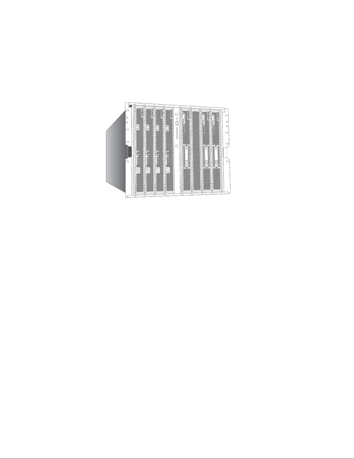
BladeSymphony 1000 (Figure 1) is the first blade system designed specifically for enterprise-class,
mission-critical workloads. It is a 10 rack unit (RU) system that combines Hitachi’s Virtage embedded
virtualization technology, a choice of Intel Dual-Socket, Multi-Core Xeon and/or Intel Dual-Core Itanium
Server Blades (running Windows or Linux), centralized management capabilities, high-performance
I/O, and sophisticated reliability, availability, and serviceability (RAS) features.
Figure 1. BladeSymphony 1000 front view
Enterprise-Class Capabilities
With BladeSymphony 1000, it is now possible for organizations to run mission-critical applications and
consolidate systems and workloads with confidence — at the edge, the application tier, the database
tier, or all three. BladeSymphony 1000 allows companies to run any type of workload with enterpriseclass performance, reliability, manageability, scalability, and flexibility. For example:
• BladeSymphony 1000 can be deployed at the edge tier — similar to dual-socket blade and rack
server offerings from Dell, HP, IBM, and others — but with far greater reliability and scalability than
competitive systems.
• BladeSymphony 1000 can be deployed at the application tier — similar to quad-socket blade server
offerings from HP and IBM, but with greater reliability and scalability.
• BladeSymphony 1000 ideal for the database tier — similar to the IBM p-Series or HP rack-mount
servers, but with a mainframe-class virtualization solution.
Designed with to be the first true enterprise-class blade server, the BladeSymphony 1000 provides
outstanding levels of performance, scalability, reliability, and configuration flexibility.
Performance — BladeSymphony 1000 supports both Intel Dual-Core Itanium and Dual-Core or
•
Quad-Core Xeon processors in the same chassis. Utilizing Intel Itanium processors, it delivers 64-bit
processing and large memory capacity (up to 256 GB) in an SMP configuration, as well as single
Intel Xeon blade configurations, allowing organizations to optimize for 64-bit or 32-bit workloads and
run all applications at extremely high performance. BladeSymphony 1000 also delivers large I/O
capacity for high throughput.
Scalability — BladeSymphony 1000 is capable of scaling out to eight Intel Dual-Core Itanium
•
processor-based server blades in the same chassis, or scaling up to two 16 core SMP servers with
Intel Dual-Core Itanium processor-based server blades.
4 BladeSymphony 1000 Architecture White Paper www.hitachi.com
Page 5

• Reliability — Reliability is increases through redundant components and components are hot-
swappable. Other reliability features include:
– Hitachi’s mainframe-class memory management
– Redundant switch and management modules
– Extremely reliable backplane and I/O
– Multi-configurable power supplies for N+1 or full redundancy options
– Failover protection following the N+M model — there are “M” backup servers for every “N” active
servers, so failover is cascading
– In the event of hardware failure, the system automatically detects the fault and identifies the
problem by indicating the faulty module, allowing immediate failure recovery.
Configuration Flexibility — BladeSymphony 1000 supports Itanium and/or Xeon processor-
•
based server blades, Windows and/or Linux, and industry-standard, best-of-class PCI cards
(PCI-X and PCI Express), providing flexibility and investment protection. The system is extremely
expandable in terms of processor cores, I/O slots, memory, and other components.
Data Center Applications
With its enterprise-class features, BladeSymphony 1000 is an ideal platform for a wide range of data
center scenarios, including:
•
Consolidation — BladeSymphony 1000 is an excellent platform for server and application
consolidation because it is capable of running 32-bit and 64-bit applications on Windows or Linux,
with enterprise-class performance, reliability, and scalability.
Workload Optimization — BladeSymphony 1000 runs a wide range of compute-intensive
•
workloads on either/both Windows and Linux, making it possible to balance the overall data center
workload quickly and without disruption or downtime.
Resource Optimization — BladeSymphony 1000 enables the IT organization to increase
•
utilization rates for expensive resources such as processing power, making it possible to fine-tune
capacity planning and delay unnecessary hardware purchases.
•
Reduce Cost, Risk, and Complexity — With BladeSymphony 1000, acquisition costs are
lower than traditional rack-mount servers. Enterprises can scale up on demand in fine-grained
increments, limiting capital expenditures. BladeSymphony 1000 also reduces the risk of downtime
with built-in sophisticated RAS features. And with support for industry standards such as Windows
and Linux, Itanium and Xeon processors, and PCI-X and PCI Express (PCIe) I/O modules,
BladeSymphony 1000 is designed for future and protects previous investments in technology.
www.hitachi.com BladeSymphony 1000 Architecture White Paper 5
Page 6
Chapter 2
System Architecture Overview
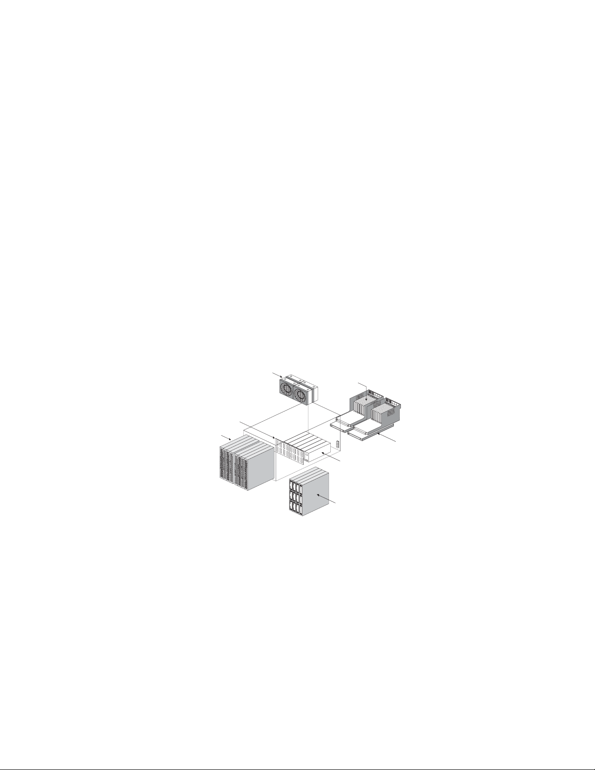
BladeSymphony 1000 features a very modular design to maximize flexibility and reliability. System
elements are redundant and hot-swappable so the system can be easily expanded without downtime
or unnecessary disruption to service levels. The key components of the system, illustrated in Figure 2,
consist of:
• Server Blades — Up to eight depending on module, available with Intel Xeon or Itanium processors
• Storage Modules — up to two modules supporting either three or six SCSI drives
• I/O Modules — available with PCI-X slots, PCIe slots, or Embedded Fibre Channel Switch, up to two
modules per chassis
• Small footprint chassis containing a passive backplane — eliminates a number of FC and network
cables
• Redundant Power Modules — up to four hot-swap (2+1 or 2+2) modules per chassis for high
reliability and availability
• Redundant Cooling Fan Modules — four hot-swap (3+1) per chassis standard configuration for high
reliability and availability
• Switch & Management Modules — hot-pluggable system management board, up to two modules
per system for high reliability and availability
Cooling fan module
I/O module
Backplane
Server blade
Power module
Storage module
Switch &
management
module
Figure 2. Key BladeSymphony 1000 components
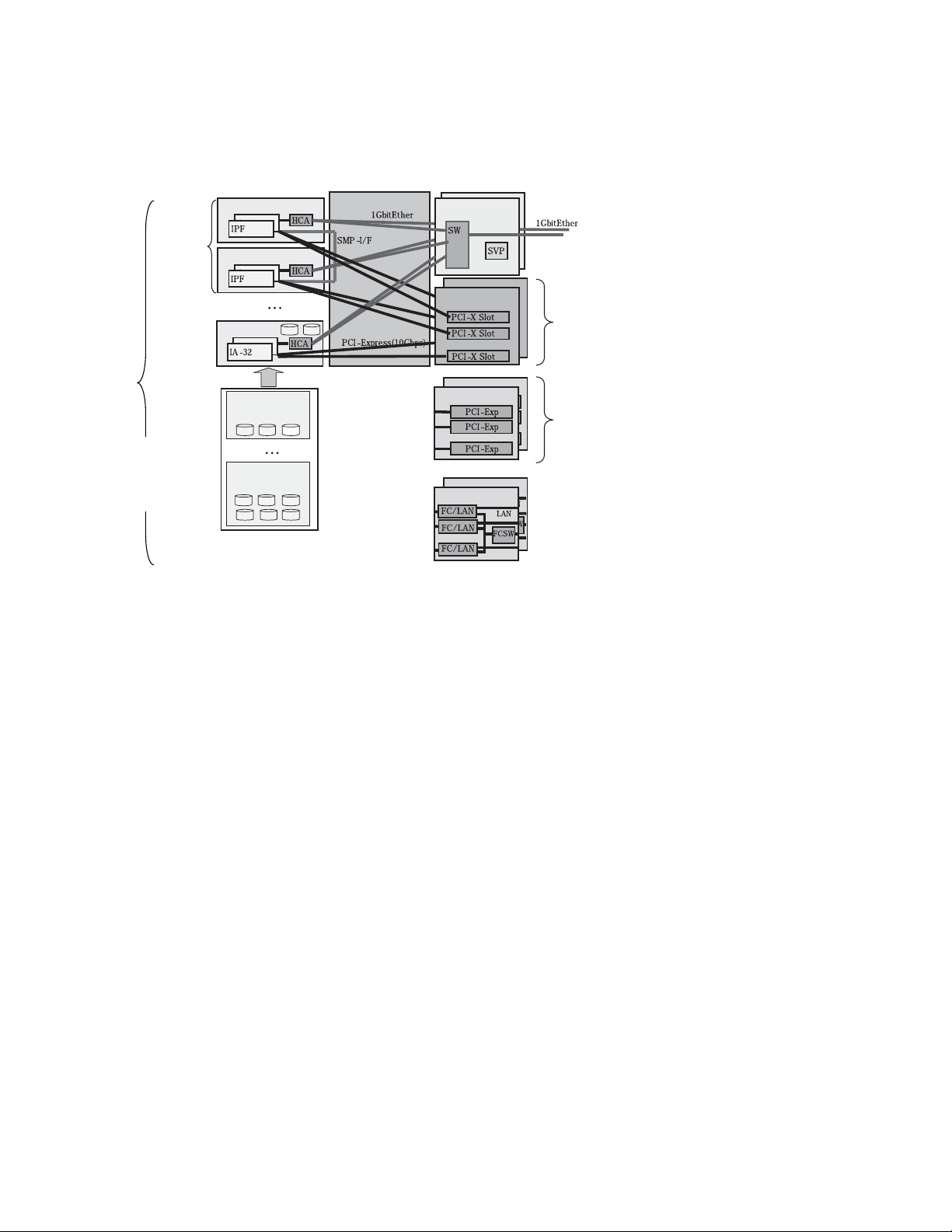
The server blades and I/O modules are joined together through a high speed backplane. Two types of
server blades are available: Intel Xeon Server Blade and Intel Itanium Server Blade. A 10 RU
BladeSymphony 1000 server chassis can accommodate eight server blades of these types. It can also
accommodate a mixture of server blades, as well as storage modules. In addition, multiple Intel
Itanium Server Blades can be combined to build multiple Symmetric Multi Processor (SMP)
configurations. Figure 3 shows a logical diagram of modules interconnecting on the backplane for a
possible configuration with one SMP server and one Intel Xeon server, as well as various options for
hard drive and I/O modules.
6 BladeSymphony 1000 Architecture White Paper www.hitachi.com
Page 7
8 modules
max.
Front
Rear
Server blade
(3 HDDs max.)
Backplane
r
Management module
Embedded FCSW
module
Server blade
Up to
8-way
SMP
configurable
r
(6 HDDs max.)
Replaced with
4-server bl ade
16 slots
in total
16 slots
in total
*1: The HDD module
having six HDD s
mounted occupies
the space for two
modules.
Server blade
HDD module
Switch &
I/O module
o
I/O module
HDD module
o
Figure 3. Logical components of the BladeSymphony 1000
The following chapters detail the major components of BladeSymphony 1000, as well as management
software and Virtage embedded virtualization technology.
• “Intel Itanium Server Blade” on page 8 provides details on the Intel Itanium Server Blades and how
they can be combined to create SMP systems up of to 16 cores and 256 GB of memory.
• “Intel Xeon Server Blade” on page 20 provides details on the Intel Xeon Server Blades.
• “I/O Sub System” on page 26 provides details on the PCI-X, PCIe, and Embedded Fibre Channel
Switch modules.
• “Chassis, Power, and Cooling” on page 36 provides details on the two chassis models, as well as
Power and Cooling Fan Modules.
• “Reliability and Serviceability Features” on page 39 discusses the various reliability, availability, and
serviceability features of the BladeSymphony 1000.
• “Management Software” on page 45 discuss software management features.
• “Virtage” on page 48 provides technical details on Virtage embedded virtualization technology.
www.hitachi.com BladeSymphony 1000 Architecture White Paper 7
Page 8
Chapter 3
Intel Itanium Server Blade
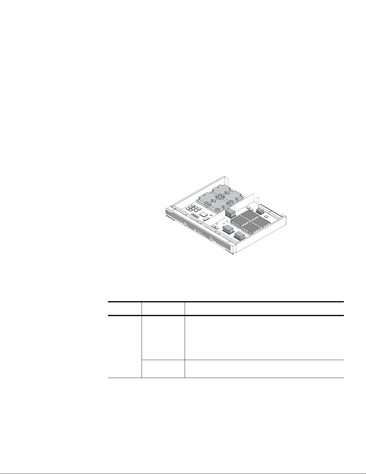
The BladeSymphony 1000 can support up to eight blades for a total of up to 16 Itanium CPU sockets,
or 32 cores, running Microsoft Windows or Linux. Up to four Intel Itanium Server Blades can be
connected via the high-speed backplane to form a high-performance SMP server of up to 16 cores.
Each Intel Itanium Server Blade, illustrated in Figure 4, includes 16 DDR2 main memory slots. Using
4 GB DIMMs, this equates to 64 GB per server blade (16 GB per core) or 256 GB in a 16 core SMP
configuration, making it an ideal candidate for large in-memory databases and very large data sets.
Each server blade also includes two gigabit Ethernet ports, which connect to the internal gigabit
Ethernet switch in the chassis, as well as two front-side accessible USB 1.1 ports for local media
connectivity and one RS-232 port for debugging purposes.
Figure 4. Intel Itanium Server Blade
Intel Itanium Server Blades include the features listed in Table 1.
Table 1: Intel Itanium Server Blade features
Item Specifications
Processors Processor
model and
maximum
number of
installed
processors
SMP
configuration
Intel® Itanium® 2 Processor 9100 series, 1.66 GHz L3=24 MB
FSB=667 MHz: 2
Intel Itanium Processor 9100 series, 1.66 GHz L3=18 MB
FSB=667 MHz: 2
Intel Itanium Processor 9100 series, 1.42 GHz L3=12 MB
FSB=400 MHz: 2
Maximum 16 cores with four server blade configuration
8 BladeSymphony 1000 Architecture White Paper www.hitachi.com
Page 9

Table 1: Intel Itanium Server Blade features
Item Specifications
Memory Capacity Max. 64 GB/server blade (if 4 GB DIMM is used)
Type DDR2 240-pin registered DIMM, 1 rank, 2 rank
Frequency: DDR2-400 3-3-3
Capacity: 512 MB, 1 GB, 2 GB, 4 GB (DDR2-533)
Configuration: 4 bit x 18 devices, 36 devices
Availability Advanced ECC, on-line spare memory, and scrubbing supported
Backplane
interface
Node link for
SMP
Three interconnect ports
PCI Express x 4 links, 2 ports
Gigabit Ether-
GbE (SerDes 1.25 Gb/sec.) 2 ports, Wake on LAN supported
net
USB Two ports per partition
Fast Ethernet
Two100Base/10Base ports
(LAN management)
I2C One port
Interface
on the front
of module
USB Two ports per physical partition
Compatible with USB 1.1
Serial One RS-232C port, for debugging only
I/O function SCSI or RAID None (I/O module required for this function
VGA None (I/O module required for this function)
Table 2 provides details on each of the components in the Itanium Blade.
Table 2: Main components of the Intel Itanium Server Blade
Component Manufacturer Quantity Description
Processor Intel Maximum 2 Intel Itanium
Node Controller (NDC)
Hitachi 1 Node controller — controls each system
bus
MC Hitachi 2 Memory controller
DIMM Maximum 16 DDR2 SDRAM
www.hitachi.com BladeSymphony 1000 Architecture White Paper 9
Page 10

Table 2: Main components of the Intel Itanium Server Blade
Component Manufacturer Quantity Description
Bridge Intel 1 PCIe to PCI-X bridge
South Bridge Intel 1 South bridge — connects legacy devices
SIO SMSC 1 Super I/O chip — contains the COM port
and other legacy devices
FW ROM ATMEL/
STMicro
Gigabit
Ethernet
USB controller VIA 1 Compatible to UHCI and EHCI
BMC Renesas 1 Management processor
BMC SRAM Renesas 2 MB, with
FPGA Xilinx 1 Controls the BMC bus, decodes addresses
Flash ROM Fujitsu 16 MB Backs up BMC codes and SAL
BUS SW
switching over
BMC-SVP
Intel 1 Gigabit Ethernet interface controller, two
8 MB A flash ROM storing the images of system
firmware
Also used as NVRAM under the control of
the system firmware
ports, SerDes connection
Wake on LAN supported
TagVLAN supported
PXE Boot supported
Main memory for management processor
parity
and functions as a bridge for LPC
1 Reserved for the SVP duplex (future)
Intel Itanium Processor 9100 Series
The Dual-Core Intel Itanium 9100 series 64-bit processor delivers scalable performance with two highperformance cores per processor, memory addressability up to 1024 TB, 24 MB of on-die cache, and a
667 MHz front-side bus. It also includes multi-threading capability (two threads per core) and support
for virtualization in the silicon.
Explicitly Parallel Instruction Computing (EPIC) technology is designed to enable parallel throughput on
a enormous scale, with up to six instructions per clock cycle, large execution resources
(128 general-purpose registers, 128 floating point registers and 8 branch registers) and advanced
capabilities for optimizing parallel throughput.
The processors deliver mainframe-class reliability, availability, and serviceability features with advanced
error detection and correction and containment across all major data pathways and the cache
subsystem. They also feature integrated, standards-based error handling across hardware, firmware,
and the operating system.
10 BladeSymphony 1000 Architecture White Paper www.hitachi.com
Page 11

The Intel Itanium is optimized for dual processor-based platforms and clusters and includes the
following features:
• Wide, parallel hardware based on Itanium architecture for high performance
– Integrated on-die cache of up to 24 MB, cache hints for L1, L2, and L3 caches for reduced
memory latency
– 128 general and 128 floating-point registers supporting register rotation
– Register stack engine for effective management of processor resources
– Support for predication and speculation
• Extensive RAS features for business-critical applications
– Full SMBus compatibility
– Enhanced machine check architecture with extensive ECC and parity protection
– Enhanced thermal management
– Built-in processor information ROM (PIROM)
– Built-in programmable EEPROM
– Socket Level Lockstep
– Core Level Lockstep
• High bandwidth system bus for multiprocessor scalability
– 6.4 GB/sec. bandwidth
– 28-bit wide data bus
– 400 MHz and 533 data bus frequency
– 50-bits of physical memory addressing and 64-bits of virtual addressing
• Two complete 64-bit processing cores on one chip running at 104W
Cache
The processor supports up to 24 MB (12 MB per core) of low-latency, on-die L3 cache (14 cycles)
providing 102 GB/sec. aggregate bandwidth to the processor cores. It also include separate 16 KB
Instruction L1 and 16 KB Data L1 cache per core, as well as separate 1 MB Instruction L2 and 256 KB
Data L2 cache per core for higher speed and lower latency memory access.
Hyper-Threading Technology
Hyper-Threading Technology (HT Technology) enables one physical processor to transparently appear
and behave as two virtual processors to the operating system. With HT Technology, one dual-core
processor is able to simultaneously run four software threads. HT Technology provides thread-level
parallelism on each processor, resulting in more efficient use of processor resources, higher processing
throughput, and improved performance on multi threaded software, as well as increasing the number of
users a server can support. In order to leverage HT Technology, SMP support in the operating system is
required.
Intel Cache Safe Technology and Enhanced Machine Check Architecture
Intel Cache Safe Technology is an automatic cache recovery capability that allows the processor and
server to continue normal operation in case of cache error. It automatically disables cache lines in the
event of a cache memory error, providing higher levels of uptime.
www.hitachi.com BladeSymphony 1000 Architecture White Paper 11
Page 12

Enhanced Machine Check Architecture provides extensive error detection and address/data path
correction capabilities, as well as system-wide ECC protection. It detects bit-level errors and manages
data corruption, thereby providing better reliability and uptime.
Intel VT Virtualization Technology
The Dual-Core Intel Itanium processor includes hardware-assisted virtualization support that helps
increase virtualization efficiency and broaden operating system compatibility. Intel Virtualization
Technology (Intel VT) enables one hardware platform to function as multiple virtual platforms.
Virtualization solutions enhanced by Intel VT allow a software hypervisor to concurrently run multiple
operating systems and applications in independent partitions.
Demand Based Switching
The Demand Based Switching (DBS) function reduces power consumption by enabling the processor
to move to power-saving mode when under a low system load. The DBS function must be supported
by the operating system.
Hitachi Node Controller
The Hitachi Node Controller controls various kinds of system busses, including the front side bus (FSB),
a PCIe link, and the node link. The Hitachi Node Controller is equipped with three node link ports to
combine up to four server blades. The server blades connect to each other through the node link,
maintain cache coherence collectively, and can be combined to form a ccNUMA type multiprocessor
configuration. The Hitachi Node Controller is connected to memory modules through memory
controllers.
The Hitachi Node Controller provides the interconnection between the two processors, two memory
controllers, three PCI bus interfaces, and connection to up to three other Intel Itanium Server Blades.
Three x 5.3 GB/sec. links can connect up to three other Intel Itanium Server Blades over the backplane
in order to provide 8, 12, or 16 core SMP capabilities. These direct connections provide a distinct
performance advantage by eliminating the need for a cross bar switch found in most SMP system
designs, which reduces memory access latency across server blades.
The Hitachi Node Controller is equipped with three PCIe ports to connect to I/O devices. Two of the
PCIe ports are used to connect to the I/O modules. The remaining port connects to an onboard I/O
device installed on the server blade, which serves a gigabit Ethernet controller, USB controller, and
COM ports.
The Hitachi Node Controller is designed for high performance processors and memory. Throughput
numbers to the processors, memory, and other nodes are listed in Table 3.
Table 3: Bus throughput from the Hitachi Node Controller
Bus Throughput
Processor bus 400 MHz FSB = 6.4 GB/sec.
667 MHz FSB = 10.6 GB/sec.
Memory bus 400 MHz FSB = 4.8 GB/sec.
667 MHz FSB = 5.3 GB/sec.
12 BladeSymphony 1000 Architecture White Paper www.hitachi.com
Page 13
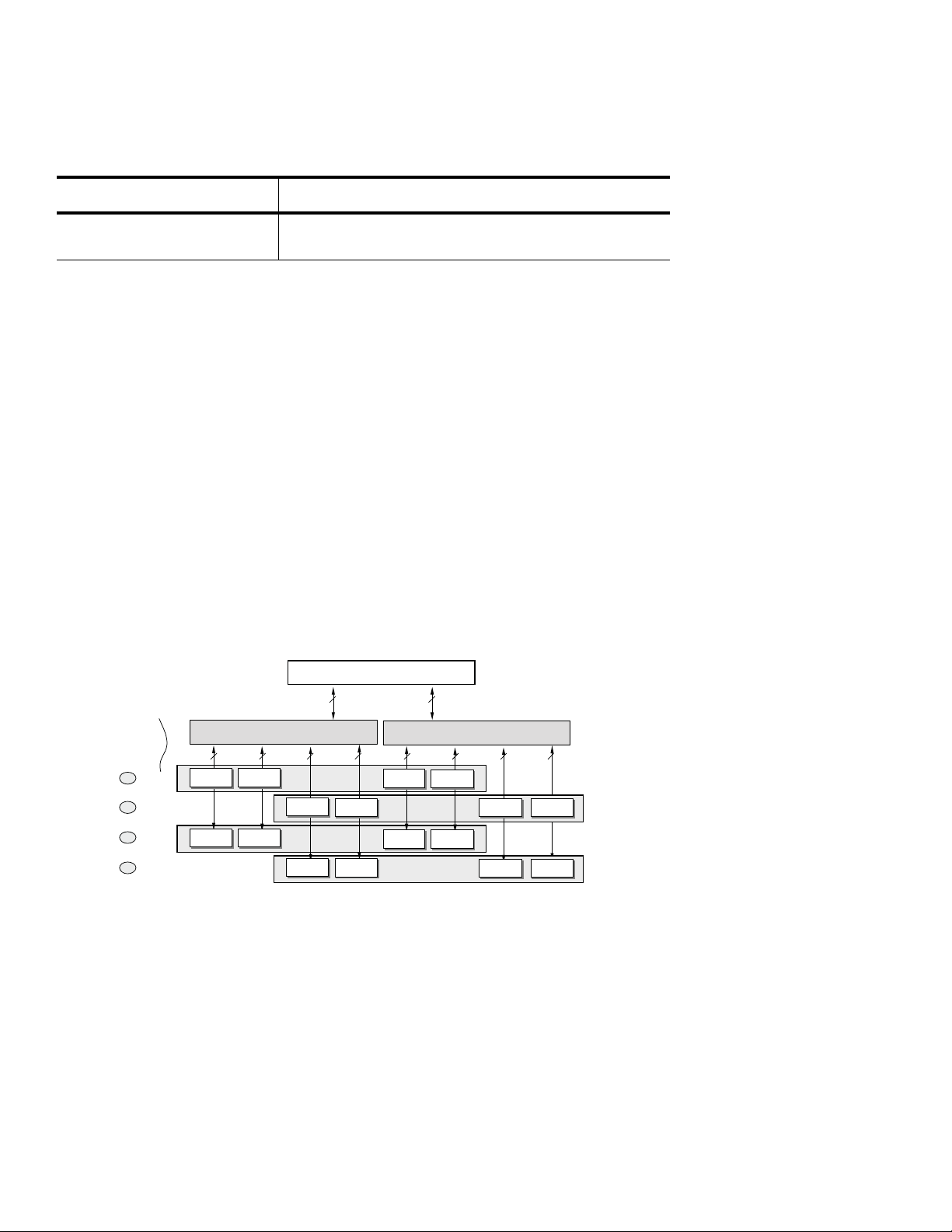
Table 3: Bus throughput from the Hitachi Node Controller
Priority
of DIMM- set
mounting
4
3
2
1
Row 45
Row 67
Row 01
Row 23
Logical
Name of
DIMM sets
72 bit
DIMM1A0
DIMM1A0
DIMM1B0
DIMM1B0
DIMM1C0
DIMM1C0
DIMM1D0
DIMM1D0
DIMM1A1
DIMM1A1
DIMM1B1
DIMM1B1
DIMM1C1
DIMM1C1
DIMM1D1
DIMM1D1
MC1
MC1
DIMM0A0
DIMM0A0
DIMM0B0
DIMM0B0
DIMM0C0
DIMM0C0
DIMM0A1
DIMM0A1
DIMM0B1
DIMM0B1
DIMM0C1
DIMM0C1
MC0
MC0
NDC
NDC
72 bit 72 bit 72 bit 72 bit 72 bit 72 bit 72 bit
72 bit72 bit
DIMM0D0
DIMM0D0
DIMM0D1
DIMM0D1
Bus Throughput
Connection between nodes 400 MHz FSB = 4.8 GB/sec.
667 MHz FSB = 5.3 GB/sec.
Baseboard Management Controller
The Baseboard Management Controller (BMC) is the main controller for Intelligent Platform
Management Interface (IPMI), a common interface to hardware and firmware used to monitor system
health and manage the system. The BMC manages the interface between system management
software and the hardware in the server blade. It is connected to the service processor (SVP) inside the
Switch & Management Module. The BMC and SVP cooperate with each other to control and monitor
the entire system. Sensors built into the system report to the BMC on different parameters such as
temperature, cooling fan speeds, power, mode, OS status, etc. The BMC can send alerts to the system
administrator if the parameters vary from specified preset limits, indicating a potential failure of a
component or the system.
Memory System
Intel Itanium Server Blades are equipped with 16 DIMM slots, which support Registered DDR2-400
SDRAM in 512 MB, 1 GB, 2 GB, and 4 GB (DDR2-533) for a total of up to 64 GB per server blade, or
16 GB per core. The memory system is designed to control a set of four DIMMs for the ECC and the
memory-device replacing function. Accordingly, if DIMMs are added, they must be arranged in four
DIMM units. The different DIMMs in each row can be used logically as shown in Figure 5.
Figure 5. Memory configuration
The memory system of the Intel Itanium Server Blade includes several RAS features:
• ECC protection (S2EC-D2ED) — Detects an error in any two sets of consecutive two bits and
corrects errors in any one set of consecutive two bits.
www.hitachi.com BladeSymphony 1000 Architecture White Paper 13
Page 14

• ECC — The ECC can correct an error in consecutive four bits in any four DIMM set (i.e., a fault in one
DRAM device). This function is equivalent to technology generally referred to as Chipkill and allows
the contents of memory to be reconstructed even if one chip completely fails. The concept is similar
to the way RAID protects content on disk drives.
• Memory device replacing function — The NDC and MC have a function to replace a faulty DRAM
device with a normal spare one assisted by the System Abstraction Layer (SAL) firmware. This keeps
the ECC function (S2EC-D2ED) operating. It can replace up to two DRAM devices in any one set of
four DIMMs.
• Memory hierarchy table (size, bandwidth/latency)
• L1 cache
• L2 cache
• L3 cache
• On board memory
• Off board memory
• Interleaved vs. non-interleaved memory configuration
• ccNUMA (cache coherent Non-uniform memory access) description
SMP Capabilities
While dual processors systems are now common place, increasing the number of processors/sockets
beyond two poses many challenges in computer design, particularly in the memory system. As
processors are added to a system the amount of contention for memory access quickly increases to
the point where the intended throughput improvement of more processors is significantly diminished.
The processors spend more time waiting for data to be supplied from memory than performing useful
computing tasks. Conventional uniform memory systems are not capable of scaling to larger numbers
of processors due to memory bus contention. Traditional large SMP systems introduce cross bar
switches in order to overcome this problem. However, this approach adds to the memory hierarchy,
system complexity, and physical size of the system. SMP systems typically do not possess the
advantages of blade systems, e.g., compact packaging and flexibility.
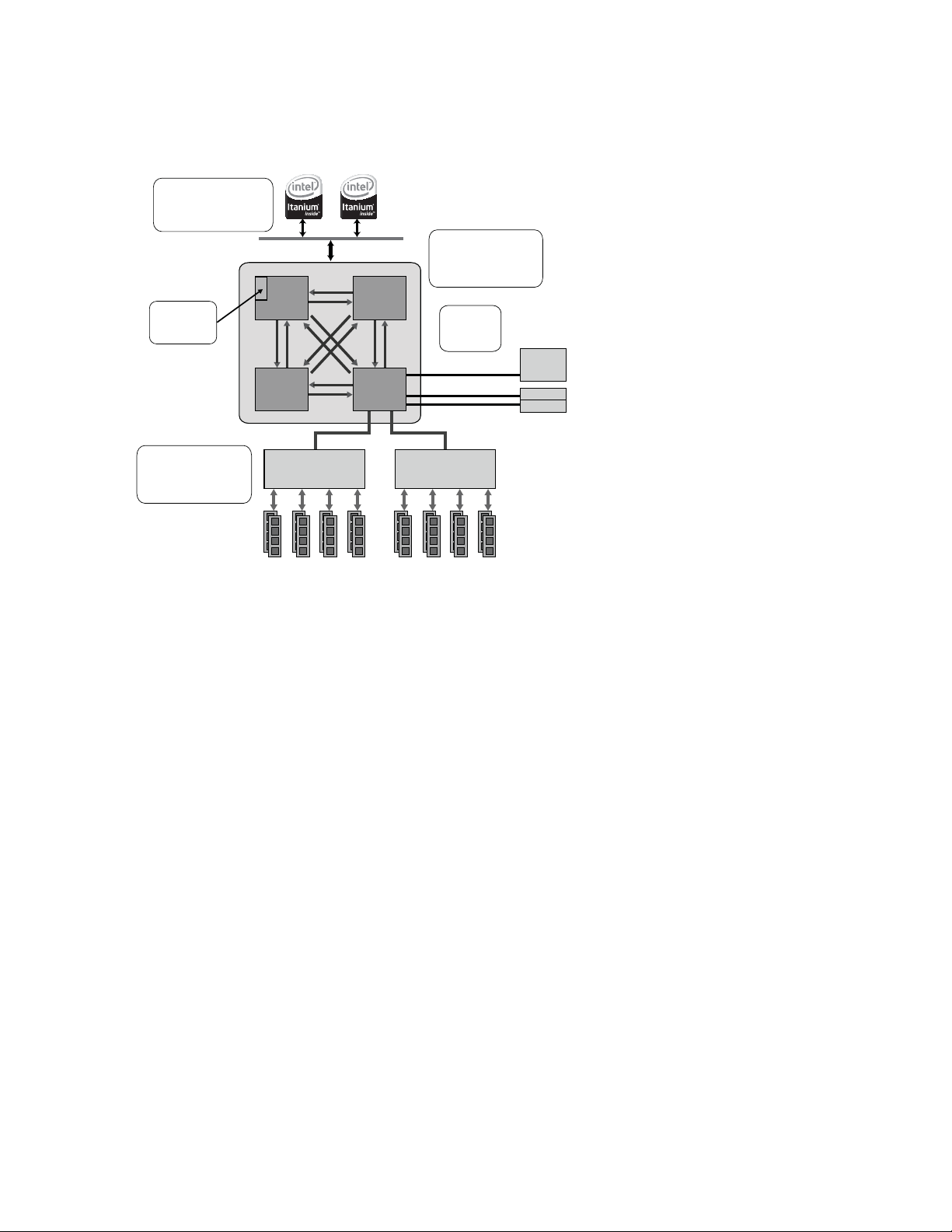
Leveraging their extensive mainframe design experience, Hitachi employs a number of advanced
design techniques to create a blade-based SMP system, allowing the BladeSymphony 1000 to scale
up to an eight socket, 16 core system with as much as 256 GB of memory. The heart of the design is
the Hitachi custom designed Node Controller, which effectively breaks a large system into smaller, more
flexible nodes or server blades in blade format. These server blades can act as complete, independent
systems or up to four server blades can be connected to form a single, efficient multi-processor
system, as illustrated in Figure 6.
14 BladeSymphony 1000 Architecture White Paper www.hitachi.com
Page 15
MC
Memory
Controller
MC
Memory
Controller
DDR2
Memory
DDR2
Memory
PCI
Bridge
PCI
Slots
PCI-Express (4 Lane)
PCI Bus
2GB/s x3
Processor Bus
6.4 GB/s
(FSB400MHz)
10.6 GB/s
(FSB667MHz)
Memory Bus
4.8 GB/s
(FSB400MHz)
5.3 GB/s
(FSB667MHz)
L3 Cache
Copy Tag
Node Bandwidth
4.8 GB/s
(FSB400MHz)
5.3 GB/s
(FSB667MHz)
CC-Numa
Point to point
Low Latency
NDC
Node
Controller
NDC
Node
Controller
NDC
Node
Controller
NDC
Node
Controller
Figure 6. Hitachi Node Controller connects multiple server blades
By dividing the SMP system across several server blades, the memory bus contention problem is
solved by virtue of the distributed design. A processor’s access to its on-board memory incurs no
penalty. The two processors (four cores) can access up to 64 GB at the full speed of local memory.
When a processor needs data that is not contained in its locally attached memory, its node controller
needs to contact the appropriate other node controller to retrieve the data. The latency for retrieving
that data is therefore higher than retrieving data from local memory. Since remote memory takes longer
to access, this is known as a non-uniform memory architecture (NUMA). The advantage of using nonuniform memory is the ability to scale to a larger number of processors within a single system image
while still allowing for the speed of local memory access.
While there is a penalty for accessing remote memory, a number of operating systems are enhanced to
improve the performance of NUMA system designs. These operating systems take into account where
data is located when scheduling tasks to run on CPUs, using the closest CPU where possible. Some
operating systems are able to rearrange the location of data in memory to move it closer to the
processors where its needed. For operating systems that are not NUMA aware, the BladeSymphony
1000 offers a number of memory interleaving options that can improve performance.
The Node Controllers can connect to up to three other Node Controllers providing a point-to-point
connection between each Node Controller. The advantage of the point-to-point connections is it
eliminates a bus, which would be prone to contention, and eliminates the cross bar switch, which
reduces contention as a bus, but adds complexity and latency. A remote memory access is streamlined
because it only needs to pass through the two Node Controllers, this provides less latency when
compared to other SMP systems.
www.hitachi.com BladeSymphony 1000 Architecture White Paper 15
Page 16
SMP Configuration Options
4-way
Server
SMP Interconnect
Backplane
SMP Interconnect
Backplane
16-way
Server
8-way
Server
OSOSOS
BladeSymphony 1000 supports two socket (four-core) Intel Itanium Server Blades that can be scaled to
offer up to two 16 core servers in a single chassis or eight four core servers, or a mixture of SMP and
single module systems, thus reducing footprint and power consumption while increasing utilization and
flexibility. SMP provides higher performance for applications that can utilize large memory and multiple
processors, such as large databases or visualization applications.
The maximum SMP configuration supported by BladeSymphony 1000 is:
• Four Dual Core Intel Itanium Server Blades for a total of 16 CPU cores
• 256 GB memory (64 GB per server blades x 4)
• Eight gigabit NICs (2 on-board per server blade) connected to two internal gigabit Ethernet switches
• Eight PCI-X slots (or 16 PCI-X slots with chassis B)
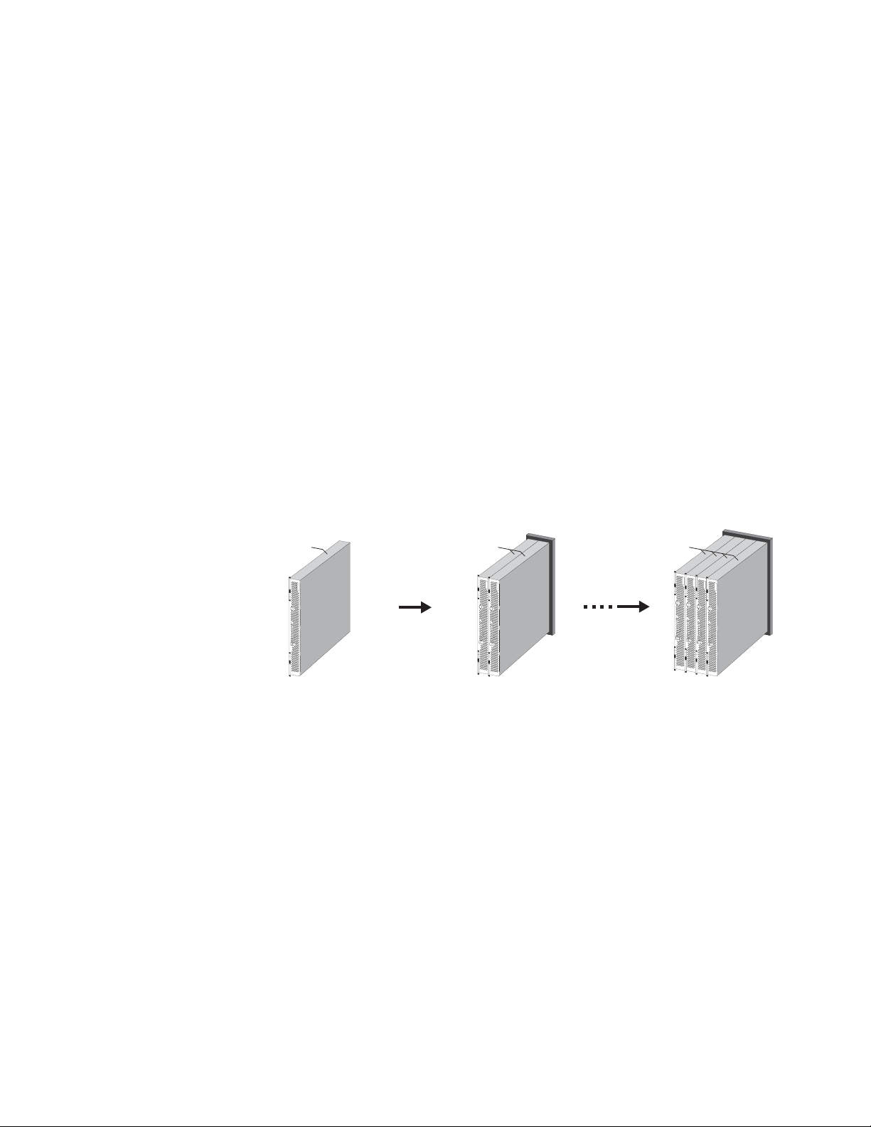
With its unique interconnect technology, BladeSymphony 1000 delivers a new level of flexibility in
adding computing resources to adapt to changing business needs. BladeSymphony 1000 can address
scalability requirements by scaling-out (horizontally), or by scaling-up (vertically). Scaling out is ideally
suited to online and other front-end applications that can divide processing requirements across
multiple servers. Scaling out can also provide load-balancing capabilities and higher availability through
redundancy.
Figure 7. Scale-up capabilities
Scaling up is accomplished through SMP, shown in Figure 7. This approach is better suited to
enterprise-class applications requiring 64-bit processing, high computational performance, and large
memory addressability beyond that provided in a typical x86 environment. BladeSymphony 1000 SMP
Interconnect technology and blade form factor allow IT staff to manage scale-up operations on their
own, without a service call. The interconnect allows up to four server blades to be joined into a single
server environment composed of the total resources (CPU, memory, and I/O) resident in each module.
NUMA Architecture
The Intel Itanium Server Blade supports two memory interleave modes, full and non-interleave.
In full interleave mode, the additional latency in accessing memory on other server blades is averaged
across all memory, including local memory, to provide a consistent access time. In non-interleave
mode, a server blades has faster access to local memory than to memory on other server blades. Both
of these options are illustrated in Figure 8.
16 BladeSymphony 1000 Architecture White Paper www.hitachi.com
Page 17

• Full interleave mode (or SMP mode) — Intended for use with an OS without support for the NUMA
CPU Module#0CPU Modu le#1CPU Modu le#2CPU Module
#3
Memory
8GB
Memory
8GB
Shows segment of memory
4 node
interleave
Interleave boundary local memory 50.0%
4GB
Memory
8GB
Memory
8GB
2-0 3-00-0 1-0
2-0
4 node
interleave
3-0
no interleaved
(local
0-0 1-0
no interleaved
(local memory)
2-1
3-1
1-1
0-1
Interleave boun dary local memory0%
Interleave boundary local memory 100.0%
Interleave boundary loc al memory0%
Interleave boundary local memory
Interleave boundary local memory 100.0%
architecture or with inadequate support for NUMA. In full interleave mode, main memory is
interleaved between CPU modules in units. Since memory accesses do not concentrate on one
CPU module in full interleave mode, memory bus bottlenecks are less likely and latency is averaged
across CPUs.
• Non-interleave mode — This mode specifies the ratio of local memory at a constant rate. Use noninterleave mode with an OS that supports NUMA. In non-interleave mode, memory is not interleaved
between CPU modules. An OS supporting NUMA performs process scheduling and memory
allocation so that memory accesses by processors only take place within the subject node (CPU
module). An OS with APIs for NUMA also allows applications running on it to perform optimization,
taking advantage of node-localized memory accesses and enabling higher system performance.
Figure 8. Full interleave mode and non-interleave mode
• Mixture mode — This mode specifies the ratio of a local memory at a constant rate. There can be
some restrictions on the ratio of local memory, according to the NUMA function support level of
operating system in use. Figure 9 shows examples of all three types of modes.
0-1
0-0
Figure 9. Examples of interleaving
2-1
2-0
1-1
1-0
3-1
3-0
3-1
2-1
-
-
www.hitachi.com BladeSymphony 1000 Architecture White Paper 17
Page 18

L3 Cache Copy Tag
The data residing in caches and main memory across Intel Itanium Server Blades are kept in sync by
using a snooping cache coherency protocol. When one of the Intel Itanium processors needs to access
memory, the requested address is broadcast by the Hitachi Node Controller. The other Node
Controllers that are part of that partition (SMP) listen for (snoop) those broadcasts. The Node Controller
keeps track of the memory addresses currently cached in each processor’s on-chip caches by
assigning a tag for each cache entry. If one of the processors contains the requested data in its cache it
initiates a cache-to-cache transfer. This reduces latency by avoiding the penalty to retrieve data from
main memory and helps maintain consistency by sending the requesting processor the most current
data. In order to save bandwidth on the processors’ front side bus, the Node Controller is able to use
the L3 Cache Copy Tags to determine which memory address broadcasts its two local processors
need to see. If a requested address is not in the processors’ cache, the Node Controller filters the
request and does not forward the request to the local processors. This process is illustrated in
Figure 10.
Node 0
Itanium2 Itanium2
L3 C
(1)
Copy
Node
Tag
Controller
Memory
Controller
Memory
Controller
Main Memory
(2)
(4)
Node 1
Itanium2 Itanium2
(3)’
Node
Controller
(3)
Memory
Controller
Memory
Controller
Main Memory
L3 C
Copy
Tag
(1) Cache consistency
control within a local node
(2) Memory
address
broadcasting
(3)
Memory
access
Parallel
Processing
(4) Memory data transfer
or
Cache data transfer
(3)’ Cache
consistency
control over
remote nodes
Figure 10. L3 cache copy tag process
Intel Itanium I/O Expansion Module
Some applications require more PCI slots than the two that are available per server blade. The Intel
Itanium I/O Expansion Module provides more ports, without the expense of additional server blades.
Using the Itanium I/O Expansion Module with the Intel Itanium Server Blade can increase the number of
the PCI expansion-card slots that can be connected to the Intel Itanium Server Blade. The Itanium I/O
expansion module cannot be used in with the Intel Xeon Server Blade.
The Intel Itanium I/O Expansion Module increases the number of PCI I/O slots to either four or eight
slots depending on the chassis type. The type A chassis enables connection to four PCI I/O slots
(Figure 11), and the type B chassis enables up to eight PCI I/O slots (Figure 12).
18 BladeSymphony 1000 Architecture White Paper www.hitachi.com
Page 19

s
6
4
0
U
0
5
EBS Chassis
k
IO Module #0 (Type1)
GB
Switch
SVP
GB
Switch
SVP
IO Module #1 (Type 2)
CPUCPU
#15 #14 #13 #1 2 #11 #10 #9 #8 #7 #6 #5
0
PXH PXH PXH PXH PXH PXH
&
#1
IPF I/O
expansion
module
Server slot #7
Server blade
Server chassis
(Type D)
Management
module #1
Management
module #0
Server slot #6 Server slot #5 Server slot #4 Server slot #3 Server slot #2 Server slot #1 Server slot #0
Backplane
CPU #7CPU #
CPU slot #6
CPU slot #7
CPU slot #
CPU slot #4 CPU slot #2
CPU #5CPU #
Node Link
(for SMP connections)
CPU slot #3
CPU module #0
Mem
CPU slot #0
PCI Expres
x4 Link
CPUCP
IPF I/O
expan-
sion
module
CPU slot #1
CPU #1 CPU #
NDC
SVP
SVP
Module #1
Switch
GB
SVP
SVP
Module #0
GB
Switch
IO Module #1 (Type 1)
#15 #14 #13 #12 #11 #10 #9 #8 #7 #6 #5 #4 #3 #2 #1 #
PCI-X slot
IO Module #0 (Type1)
Bridge BridgeBridge BridgeBridgeBridgeBridgeBridge
Figure 11. Intel Itanium I/O Expansion Module in type A chassis provides up to four PCI slots per server
blade
#0
NDC
Mem.
Backplane
PCI Expr ess
x4 Lin
PXH
Switch &
PXH
&
Switch &
I/O module #1 (type 1) I/O module #0 (type 1)
#0
PCI slot
#4 #3 #2 #1 #
Figure 12. Intel Itanium I/O Expansion Module in type B chassis provides up to eight PCI slots per
server blade
www.hitachi.com BladeSymphony 1000 Architecture White Paper 19
Page 20

Chapter 4
Intel Xeon Server Blade
The eight slot BladeSymphony 1000 can accommodate a total of up to eight Dual-Socket, Dual-Core
or Quad-Core Intel Xeon Server Blades for up to 64 cores per system. Each Intel Xeon Server Blade
supports up to four PCI slots, and provides the option of adding Fibre Channel or SCSI storage. Two
on-board gigabit Ethernet ports are also provided, along with IP KVM for remote access, virtual media
support, and front-side VGA and USB ports for direct access to the server blade.
Figure 13. Intel Xeon Server Blade
While the Intel Itanium Server Blades provide SMP and the raw performance that the Itanium
processors bring to number-crunching jobs, the Intel Xeon Server Blades, which require less power and
cooling, and are less expensive, are ideal for supporting infrastructure and application workloads, as
well as 32-bit applications. The components of the Intel Xeon Server Blade are listed in Table 4.
Table 4: Intel Xeon Server Blade components
Dual Core Intel Xeon Processor
Processor
Series
Processor Frequency
Number of Processors
Cache Memory L2: 4 MB L2: 6 MB L2: 2 x 6 MB
System Bus
(FSB) Frequency
Main Memory ECC DDR2-667 FB-DIMM Advanced ECC / Memory Mirroring
5110 Series 5140
Series
1.60 GHz 2.33 GHz 3.33 GHz 2.66 GHz 3.16 GHz
Maximum 2 (maximum 4 cores) Maximum 2 (maximum 8 cores)
1066 MHz 1333 MHz
5260 Series E5430 Series X5460 Series
Quad Core Intel Xeon
Processor
20 BladeSymphony 1000 Architecture White Paper www.hitachi.com
Page 21

Table 4: Intel Xeon Server Blade components
Dual Core Intel Xeon Processor
Capacity Maximum 32 GB
Memory Slots 8
Internal HDD Up to four 2.5 inch, 73 GB or 146 GB 10K RPM SAS HDD
Internal Expansion Slot
Network Interface
Power Consumption (Max)
Supported OS Microsoft Windows Server 2003 SP2, Standard Edition
One (dedicated for RAID card of internal SAS HDD)
1 Gigabit Ethernet (SERDES), two ports
255 W 306W 370W 370W 420W
Microsoft Windows Server 2003 SP2, Enterprise Edition
Microsoft Windows Server 2003 SP2, Standard x64 Edition
Microsoft Windows Server 2003 SP2, Enterprise x64 Edition
Red Hat Enterprise Linux ES4
Red Hat Enterprise Linux AS 4
Quad Core Intel Xeon
Processor
Intel Xeon 5200 Dual Core Processors
The Dual-Core Intel Xeon 5200 Series processors utilizes two 45 nm Hi-k next generation Intel Core
microarchitecture cores. The processors feature fast data throughput with Intel I/O Acceleration
Technology, up to 6 MB of L2 cache memory that can be allocated entirely to one core, and they
support both 32-bit and 64-bit applications. The energy-efficient processors are optimized for lowpower, dual-core, 64-bit computing.
Intel Core Mircroarchitecture integrates an efficient 14-stage pipeline and memory architecture design
for greater processor throughput with power management technologies that reduce power
consumption without affecting performance. The architecture also supports direct L1-to-L1 cache
transfer and improved memory pre-fetch.
Other technologies featured in the Intel Xeon 5200 processors include:
• Hyper-Threading Technology — described in “Hyper-Threading Technology” on page 11.
• Intel Virtualization Technology — provides hardware assistance for software-based virtual
environments to support new capabilities, including 64-bit operating systems and applications.
• Intel I/O Acceleration Technology (I/OAT) — hardware and software supported I/O acceleration that
improves data throughput. Unlike NIC-centric solutions (such as TCP Offload Engine), I/OAT is a
platform level solution that addresses packet and payload processing bottlenecks by implementing
parallel processing of header and payload. It increases CPU efficiency and delivers data to and from
applications faster with improved direct memory access (DMA) technologies that reduce CPU
utilization and memory latencies associated with data movement. Finally, I/OAT optimizes the TCP/IP
protocol stack to take advantage of the features of the high bandwidth rates of modern Intel
processors, thus diminishing the computation load on the processor.
www.hitachi.com BladeSymphony 1000 Architecture White Paper 21
Page 22

• Intel VT Flex Migration — Intel hardware-assisted virtualization provides the ability to perform live
virtual machine migration to enable fail-over, load balancing, disaster recovery, and real-time server
maintenance.
• New features include Error Correcting Code (ECC) system bus, new memory mirroring, and I/O hotplug
Intel Xeon 5400 Quad Core Processors
The Quad-Core Intel Xeon 5400 Series is designed for mainstream, new business, and HPC servers,
delivering increased performance, energy efficiency, and the ability to run applications with a smaller
footprint. Built with 45 nm enhanced Intel Core microarchitecture, the Quad-Core Intel Xeon 5400
Series delivers 8-thread, 32- and 64-bit processing capabilities with 12 MB of L2 cache per processor,
providing more computing for threaded applications in a variety of deployments.
Intel's 45 nm uses 820 million transistors in the Intel Xeon processor 5400 series (Intel Xeon processor
5300 series has 582 million transistors). More transistors deliver more capability, performance, and
energy efficiency through expanded power management capabilities. Other enhancements are
designed to reduce virtualization overhead. And 47 new Intel Streaming SIMD Extensions 4 (SSE4)
instructions can help improve the performance of media and high-performance computing applications.
Other features include:
• Fully Buffered DIMM (FBDIMM) technology that increases memory speed to 800 MHz and
significantly improves data throughput
• Memory mirroring and sparing designed to predict a failing DIMM and copy the data to a spare
memory DIMM, increasing server availability and uptime
• Support for up to 128 GB memory
• Enhanced Intel SpeedStep technology allows the system to dynamically adjust processor voltage
and core frequency, which results in decreased power consumption and heat production
Memory System
The Intel Xeon Server Blade is equipped with eight FBDIMM slots supporting Registered DDR1
SDRAM. Supported capacity includes 512 MB, 1 GB, and 2 GB, DDR1-266 DIMMs. The memory
system is designed to control a set of two DIMMs for the memory device replacing function.
Accordingly, if DIMMs are added, they must be installed in two-DIMM units. The DIMMs in the same
bank must be of the same type. The DIMMs in different banks can be of different types.
FB-DIMM Advantages
Intel supports Fully Buffered DIMM (FBDIMM) technology in the Intel Xeon 5200 dual-core and 5400
quad-core processor series. FBDIMM memory provides increased bandwidth and capacity for the Intel
Xeon Server Blade. It increases system bandwidth up to 21 GB/sec. (with DDR2-667 FBD memory).
FBDIMM technology offers better RAS by extending the currently available ECC to include protection
for commands and address data. Additionally, FBDIMM technology automatically retries when an error
is detected, allowing for uninterrupted operation in case of transient errors.
22 BladeSymphony 1000 Architecture White Paper www.hitachi.com
Page 23

Advanced ECC
Conventional ECC is intended to correct 1-bit errors and detect 2-bit errors. Advanced ECC, also
known as Chipkill, corrects up to four or eight bits of an error that occurs in a DRAM installed on a
x4- DRAM or x8-DRAM type DIMM, respectively. Accordingly, the system can operate normally even if
one DRAM fails, as illustrated in Figure 14.
Figure 14. Advanced ECC
Online Spare Memory
Online spare memory provides the functionality to switch over to spare memory if correctable errors
frequently occur. This function is enabled to prevent system downtime caused by a memory fault.
BladeSymphony 1000 supports the online spare memory function in the ten patterns of memory
configurations listed in Table 5. The shaded sections represent spare banks. Online spare memory
excludes the use of the memory mirroring function.
Table 5: Online spare memory supported configurations
Bank Bank1 Bank2 Bank3 Bank4
Slot Slot 1 Slot 2 Slot 3 Slot 4 Slot 5 Slot 6 Slot 7 Slot 8
Configuration 1 2 GB 2 GB 2 GB 2 GB 2 GB 2 GB
Configuration 2 1 GB 1 GB 1 GB 1 GB 1 GB 1 GB
Configuration 3 512
MB
Configuration 4 2 GB 2 GB 2 GB 2 GB
Configuration 5 1 GB 1 GB 1 GB 1 GB
Configuration 6 512
MB
512
MB
512
MB
512 MB 512
MB
512 MB 512
MB
512 MB 512
MB
2 GB 2 GB None None
1 GB 1 GB None None
512 MB 512
MB
2 GB 2 GB
1 GB 1 GB
512
MB
None None
512
MB
www.hitachi.com BladeSymphony 1000 Architecture White Paper 23
Page 24

Table 5: Online spare memory supported configurations
Bank Bank1 Bank2 Bank3 Bank4
Configuration 7 2 GB 2 GB
Configuration 8 1 GB 1 GB
Configuration 9 512
MB
Configuration 10256
MB
512
MB
256
MB
2 GB 2 GB None None None None
1 GB 1 GB None None None None
512 MB 512
None None None None
MB
256 MB 256
None None None None
MB
For example, in Configuration 1 the shaded BANK 4 is a spare bank. Assume that the memory
correctable errors occur frequently in a memory on BANK 3. BIOS, which keeps counting the memory
correctable errors on each bank, activates the online copy function automatically upon the incidence of
the fourth error. All of the data on BANK 3 is copied to spare BANK 4. At the same time, a log is
recorded explaining that the data is copied to the spare bank, and the system displays a message
when the online sparing is complete, at which time the system operates with BANK1, BANK2, and
BANK4 (12 GB), the same capacity as before the online spare memory operation occurred.
Memory Mirroring
Mirroring the memory provides a level of redundancy that enables the system to continue operating
without the going down in case of a memory fault (including a plural-bits error).
Figure 15. Memory mirroring
When operating in normal conditions, data first writes in the primary (slots 1, 2, 5, and 6), then in the
mirror (slots 3, 4, 7, and 8). The arrows in Figure 15 show the relationship between the mirroring source
and the destination. When data is read out, it is read out of either the primary or mirror.
No memory testing of the mirror is carried out when the system is booted up after the mirroring is set.
Accordingly, only half of the total capacity of the memory installed is displayed both in the memory test
screen shown when the system is booted and in the total memory capacity shown when the system is
running.
24 BladeSymphony 1000 Architecture White Paper www.hitachi.com
Page 25

If an uncorrectable error occurs in a DIMM in the primary, the mirror is used for both writing and reading
data. If an uncorrectable error occurs in a DIMM in the mirror, the primary is used for both writing and
reading data. In this case, the error is logged as a correctable error. If the error is uncorrectable by the
primary or mirror, it is logged as an uncorrectable error.
On-Module Storage
Intel Xeon Server Blades support up to four internal 2.5-inch SAS hard drives The SAS architecture,
with its SCSI command set, advanced command queuing, and verification/error correction, is ideal for
business-critical applications running on BladeSymphony 1000 systems.
Traditional SCSI devices share a common bus. At higher signaling rates, parallel SCSI introduces clock
skew and signal degradation. Serial Attached SCSI (SAS) solves these problems with a point-to-point
architecture where all storage devices connect directly to a SAS port. Point-to-point links increase data
throughput and improve the ability to find and repair disk failures. The SAS command set is parallel
SCSI, frame formats are from Fibre Channel, and physical characteristics are from Serial ATA. SAS links
are full duplex, enabling them to send and receive information simultaneously, which reduces latency.
The SAS interface also allows multiple links to be combined, creating 2x, 3x, or 4x connections to
increase bandwidth.
www.hitachi.com BladeSymphony 1000 Architecture White Paper 25
Page 26

Chapter 5
I/O Sub System
I/O Modules
Hitachi engineers go to great lengths to design systems that provide high I/O throughput.
BladeSymphony 1000 PCI I/O Modules deliver up to 160 Gb/sec. throughput by providing a total of up
to 16 PCI slots (8 slots per I/O module). I/O modules accommodates industry standard PCIe or PCI-X
cards, supporting current and future technologies as well as helping to preserve investments in existing
PCI cards. In addition, by separating I/O from the server blades, the BladeSymphony 1000 overcomes
the space contraint issues of other blade server designs, which can only support smaller PCI cards.
Three I/O modules are available: PCI-X I/O Module, PCIe I/O Module, and an Embedded Fibre Channel
Switch Module. Two I/O modules are supported per chassis.
PCI-X I/O Module
The PCI-X I/O Module supports eight PCI-X cards in total, with a maximum of two PCI-X cards
assigned to a single server blade for Chassis A and four for Chassis B. In Chassis A, eight PCI cards
can be attached to four server blades, at a two-to-one ratio. In Chassis B, four PCI cards can be
attached to four server blades for a four to one ratio. Hot plug is supported in specific conditions.
See the BladeSymphony 1000 Users Manual for more information. The block diagram for the PCI-X I/O
Module is shown in Figure 16.
PCI Express x4 link
PCI-X (133 MHz)
8 slot
(Hot Plug Support)
Legacy
Interrupt
Bridge Bridge Bridge Bridge
SWSW
Figure 16. PCI-X I/O Module block diagram
Legacy
Interrupt
SWSW SWSW
A2B2C2D2
SCSI
A1B1C1D1
Bus connection
SWSW
I2C SW
FRU
I2C
Reg.
Card
Status
Error LED
26 BladeSymphony 1000 Architecture White Paper www.hitachi.com
Page 27

Table 6 provides information on the connector types for PCI-X I/O Modules.
LAN
RJ45 (MAG)
LAN
RJ45 (MAG)
Flash
FC
Controller
LED
LED
ROM
Optical module
GbE
Bridge
Optical module
Table 6: PCI-X I/O Module connector types
Name Protocol Frequency Bus Width Remarks
PCI-X slots #0 to 7 PCI-X 133 133 MHz 64-bit PCI Hot Plug
SCSI connector #0, #1 Ultra 320 160 MHz 16 bit LVD Each I/O module
has two SCSI connector ports
PCIe I/O Module
To provide more flexibility and to support newer PCI cards, a PCIe I/O module is available. The PCIe I/O
Module supports eight PCIe cards in total, and one I/O module can have one PCIe card assigned per
server blade. The PCIe I/O Module uses a PCIe hot plug controller manufactured by MICREL. Hot plug
is supported for each PCIe slot in the PCIe I/O Module. The operating system must support hog plug in
order for this operation to be successful.
PCIe I/O Module Combo Card
A PCIe I/O Module Combo Card is available for the BladeSymphony 1000, which can be installed in the
PCIe I/O Module and provides additional FC and gigabit Ethernet configurations. The block diagram is
shown in Figure 17. The card includes two1/2/4 Gb/sec. FC ports supporting FC-AL and point-to-point
switch fabric. Two gigabit Ethernet ports are also included. These ports support auto-negotiation and
VLAN (compatible to IEEE 8.2.1Q and a maximum of 4096 TagVLANs).
Figure 17. PCIe I/O Combo Card block diagram
Embedded Fibre Channel Switch Module
The Embedded Fibre Channel Switch Module consists of a motherboard, with one daughter card with
an FC switch installed, and eight FC-HBA + Gigabit Ethernet Combo Cards. It enables the use of both
FC and LAN functions from each server blade in the BladeSymphony 1000 chassis. Figure 18 shows
an outside view of this module.
www.hitachi.com BladeSymphony 1000 Architecture White Paper 27
Page 28

Figure 18. Outside view of the Embedded Fibre Channel Switch Module
(2) RJ-45 conn ector
(1) Serial Port(3) Error LED
(Fiber channel switch cl ose-up)
SFP SFP SFP SFP
RJ45
(10) Fibre Channel port status LED
(green/orange, green/orange)
(7) Option LED (Green)
(8) Fibre Channel
switch status LED
(green/orange)
(9) Power status LED
(green )
(4) LAN LED Link speed (green)
(5) LAN LED Link status (orange)
(6) SFP port/SFP module
4Gbps FC-SW
SFPSFP
The Fibre Channel switch within the module consists of 14 ports compatible with the 4 Gb/sec. Fibre
Channel standard. Eight ports are connected internally to the FC-HBA of up to eight FC-HBA + Gigabit
Ethernet Combo Cards, and six of the ports are external ports used to connect to external storage.
Figure 19 depicts the back view of the module and a blow up of the Fibre Channel switch. The block
diagram for the module is shown in Figure 20.
28 BladeSymphony 1000 Architecture White Paper www.hitachi.com
Figure 19. Back view of Embedded Fibre Channel Switch Module with blow up of the Fibre Channel
switch
Page 29

48V
12V
Gl
aci er
5V
12V
3.3V
12V (mai n)
5V (Standby)
FC-SW
Processor
CPLD
else
SFP
SFP
SFP
SFP
RJ45
For management
RS232C
I2C
Hub
I2C
Reg.
I2C
UART
I2C
Local Data Bus
PCIeX4 (Server blade #1)
PCIeX4 (Server blade #2)
PCIeX4 (Server blade #3)
PCIeX4 (Server blade #4)
PCIeX4 (Server blade #5)
PCIeX4 (Server blade #
PCIeX4 (Server blade #7)
LED
ROM
82,546 GB
(GbE)
LAN
RJ45+(MAG)
PCI-X
64b 100MHz
PCI-X
64b 6MHz (4Gbs)
41210
Bridge
FC 4.25 Gbs (Max)
Con.
Five
Flash
PCI-Exp (x4)
Total 8 modules mountable
PCIeX4 (Server blade #0)
6)
Connector
Figure 20. Embedded Fibre Channel Switch Module block diagram
The Embedded Fibre Channel Switch Module is configured with three components: A Brocade Fibre
Channel switch, Fibre Channel HBAs, and network adapters. Directly connecting the HBAs to the FC
switch in this manner, rather than installing them as PCI cards in the blades eliminates the 16 fiber
cables that would be necessary to make these connections in other systems, as illustrated in Figure 21.
Another benefit is reduced latency on the data path. This dramatically reduces complexity,
administration, and points of failure in FC environments. It also reduces the effort to install and/or
reconfigure the storage infrastructure.
www.hitachi.com BladeSymphony 1000 Architecture White Paper 29
Page 30

Server blade #0
Slot #0 (Server blade #0)
Slot #1 (Server blade #1)
Slot #2 (Server blade #2)
)
Server blade #1
Server blade #2
Server blade #3
Server blade #4
Server blade #5
Server blade #6
Server blade #7
Backplane
(type D)
Corresponding server bl ades
Slot #4 (Server blade #4)
Slot #5 (Server blade #5)
Slot #6 (Server blode #6)
)
Slot #8 (Server blade #0)
Slot #9 (Server blade #1)
Slot #10 (Server blade #2)
)
Slot #12 (Server blade #4)
Slot #13 (Server blade #5)
Slot #14 (Server blade #6)
)
Slot #3 (Server bl ade #3
Slot #7(Server blode #7
Slot #11 (Server blade #3
Slot #15 (Server blade #7
30 BladeSymphony 1000 Architecture White Paper www.hitachi.com
Figure 21. Embedded Fibre Channel Switch Module connection diagram, eliminating 16 cables
Table 7 provides the details on the features of the Embedded Fibre Channel Switch module.
Table 7: Embedded Fibre Channel Switch Module components
Function Details
Supported Fibre Channel standards
FC-FG, FC_AL, FC_FLA, FC_PLDA, FC_VI, FC_PH, FC_GS_2, FC_PH_3,
FC_SW, IPFC RFC, FC_AL2, FC_PH
Fibre Channel port Universal port x14 (14 ports equipped as hardware, 8 internal ports, 6
external ports)
Port type FL_port, F_port and E_port, with the function (U_port) to self-detect port
type
Switch expandability Full-fabric architecture configured by up to 239 switches
Interoperability SilkWorm II, SilkWorm Express, and SilkWorm 2000 families
Performance 4.250 Gb/sec. (full-duplex)
Page 31

Table 7: Embedded Fibre Channel Switch Module components
Bridge
ROM
GbE
LAN
RJ45+(MAG)
LED
Con.
PCI-X
64b 66 MHz (4 Gbps)
PCI-X
133 MHz (64b)
Flash
FC
Controller
FC 4.25 Gbps
PCI-Exp (x4)
Function Details
Fabric delay time Less than 2 microseconds (no contention, cut-through routing)
Maximum frame size 2112-byte payload
Service class Class 2, class 3, class F (frame between two switches)
Data traffic type Unicast, multicast, broadcast
Media type SFP (Small Form-Factor Pluggable)
Fabric service SNS (Simple Name Server), RSCN (Registered State Change
Notification), Alias Server (Multicast), Brocade Advanced Zoning
ISL Trunking Supported
FC-HBA + Gigabit Ethernet Combo Card
The FC-HBA + Gigabit Ethernet Combo Card provides the FC-HBA and gigabit Ethernet functions for
the Embedded Fibre Channel Switch Module.
Figure 22. FC-HBA + Gigabit Ethernet Combo Card block diagram
The card includes the following components:
• One Intel PCIe to PCI-X bridge chip
• One Intel Gigabit LAN Controller
• One Hitachi FC Controller FC HBA (1 port)
www.hitachi.com BladeSymphony 1000 Architecture White Paper 31
Page 32

The Hitachi FC Controller FC-HBA supports the functions in Table 8.
Table 8: Hitachi FC Controller FC-HBA functions
Function Details
Number of ports 1
PCI hot plug Supported
Port speed 1/2/4/ Gb/sec.
Supported standards FC-PH rev.4.3, FC-AL rev. 5.8
Supported topology FC_AL, point-to-point switched fabric
Service class Class 2/3
Number of BB credits 256
Maximum buffer size 2048
RAS Error injection, trace, error detection
Intel Xeon Server Blade boot support Supported (BIOS)
Intel Itanium Server Blade boot support Supported (BIOS/EFI)
Management Software
Developed exclusively for BladeSymphony 1000, the BladeSymphony management software manages
all of the hardware components of BladeSymphony 1000 in a unified manner, including the Embedded
Fibre Channel Switch Module. In addition, Brocade management software is supported, allowing the
Embedded Fibre Channel Switch Module to be managed using existing SAN management software.
Each component can also be managed individually.
The Fibre Channel switch is managed through a 10/100M Ethernet (RJ-45) or serial port. Either port
can be used to manage the switch. The following software is supported to manage the Fibre Channel
switch:
• Brocade Web Tools — An easy-to-operate tool to monitor and manage the FC switch and SAN
fabric. Operated from a Web browser.
• Brocade Fabric Watch — SAN monitor for the switches made by Brocade. It constantly monitors the
SAN fabric to which the switch is connected, detects any possible fault, and gives the network
manager a prior warning automatically.
• Brocade ISL Trunking — Groups ISLs between switches automatically to optimize the performance
of the SAN fabric.
The Fibre Channel HBA supports Common HBA API version 1.0 (partly 2.0) developed by SNIA.
Common HBA API is a low-level HBA standard interface to access the information in the SAN
environment, and is provided as the API in the standard C language.
The network adapter supports SNMP and ACPI management software.
32 BladeSymphony 1000 Architecture White Paper www.hitachi.com
Page 33

Embedded Gigabit Ethernet Switch
The Embedded Gigabit Ethernet Switch is contained in the Switch & Management Module and is a
managed, standards-based Layer 2 switch that provides gigabit networking through cableless LAN
connections. The switch provides 12 (single) or 24 (redundant) gigabit Ethernet ports for connecting
BladeSymphony 1000 Server Blades to other networked resources within the corporate networking
structure. Eight of the ports connect through the backplane to server blades, and the remaining four
ports are used to connect to external networks, as illustrated in Figure 23. The switch provides up to 24
Gb/sec. total throughput performance and the ability to relay packets at 1,488,000 packets/sec.
Additional features are listed in Table 9.
Figure 23. Back view of chassis with blow up of Embedded Gigabit Ethernet Switch
The Embedded Gigabit Ethernet Switch can be configured for high availability and fault tolerance when
a second, redundant switch module is added. A single switch interconnects one (of two) gigabit
Ethernet connections from each blade server blade (up to eight total). The second redundant switch
interconnects each of the remaining gigabit connections for each server blade , so a single switch
failure allows networking operations to continue on the remaining switch. If additional network
bandwidth or connectivity is needed, PCI slots can be utilized for additional NICs. Switch features are
listed in Table 9.
www.hitachi.com BladeSymphony 1000 Architecture White Paper 33
Page 34

Table 9: Embedded Gigabit Ethernet Switch features
Item Description
Port Backplane side: 1 Gb/sec. x 8
External: 10 BASE-T / 100 BASE-T / 1000 BASE-t (auto connection)
Auto learning of MAC address (16,384 entries)
Switch Layer 2 switch
Bridge function Spanning tree protocol (IEEE 802.1d compliant)
Network function Link aggregation (IEEE 802.3ad)
Trunking (up to 4 ports, 24 groups)
Jumbo frame (packet size: 9216 bytes)
VLAN Port VLAN
TagVLAN (IEEE 802.1q)
Maximum number of definitions: 4096
Management function SNMP v2c agent
MIB II (RFC1213 compliant)
Interface extending MIB (FRC1573, RFC2233 compliant)
SCSI Hard Drive Modules
The BladeSymphony 1000 supports two types of storage modules containing 73 or 146 GB 15K RPM
Ultra320 SCSI drives in the type B chassis only. The 3x HDD Module can have up to three drives
installed. The 6x HDD module utilizes two server slots and can house up to six drives. Both HDD
Modules are illustrated in Figure 24. Four out of eight server slots of a server chassis can be used to
install storage modules, for a total of either four 3x modules or two 6x modules. The storage modules
are mountable only on server slots #4 to #7 in Chassis B.
Disk drives installed in HDD modules can be hot-swapped in a RAID configuration with the RAID
controller installed on the PCI card. The HDD Modules support RAID 1, 5, and 0+1 and spare disk.
Figure 24. HDD Modules
34 BladeSymphony 1000 Architecture White Paper www.hitachi.com
Page 35

A SCSI or RAID type PCI card must be installed in a PCI slot in an I/O module to act as the controller of
2
e
#
the storage module. A PCI card is combined with a storage module, as shown in Figure 25, by
connecting the SCSI cable from the PCI card to the SCSI connector on the same I/O module, and then
connecting the board wiring from the SCSI connector to server slot #4 to #7, where the storage module
is installed through the backplane. The logical numbers of the SCSI connectors on I/O module #0 and
#1 are defined as #0 to #1 and #2 to #3, respectively.
Sample Configuration
Server chassis
6x HDD SCSI i/f
6 x HDD has only one
SCSI I/F port.
Note that this port is
not connected.
{
(1) 3x HDD Module(2) 6x HDD Module
Backplan
(Type 2)
Figure 25. Connection configuration for HDD Modules
SCSI Bus
(Internally c onnect ed)
SCSI connector #2
SCSI #3
SCSI connector # 3
Bridge Bridge Bridge Bridge
#15 #14 #13 #12 #11 #10 #9 #8 #7 #6 #5 #4 #3 #2 #1 #0
I/O module #1 (type 2)
SCSI #
SCSISCSISCSISCSI
I/F #0I/F #1I/F #2I/F #3
SCSI connector # 1
Bridge Bridge Bridge Bridge
I/O module
0 (type 1)
SCSI connector #0
SCSI or RAID Card
www.hitachi.com BladeSymphony 1000 Architecture White Paper 35
Page 36

Chapter 7
LAN0
LAN1
Switch Module
#1
Switch Module
#2
Server blade #1
Server blade #2
Server blade #3
Server blade #4
Server blade #5
Server blade #6
Server blade #7
Server blade #8
Chassis Model A
LAN0
LAN1
Switch Module
#1
Switch Module
#2
Server blade #1
Server blade #2
Server blade #3
Server blade #4
Server blade #5
Server blade #6
Server blade #7
Server blade #8
Chassis Model B
Chassis, Power, and Cooling
The BladeSymphony 1000 chassis houses all of the modules previously discussed, as well as a passive
backplane, Power Supply Modules, Cooling Fan Modules, and the Switch & Management Modules.
The chassis and backplane provide a number of redundancy features including a one-to-one
relationship between server blades and I/O modules, as well as duplicate paths to I/O and switches. In
addition, although the backplane is the only single point of failure in the BladeSymphony 1000, it
intentionally uses a passive design that eliminates active components that might fail. The backplane
provides connections between server blades, SCSI HDD Modules, PCI slots, FC HBAs, and LAN
switch, thus eliminating a large number of cables, which reduces costs and complexity.
Two types of chassis are available, chassis A and chassis B. Chassis A provides connections between
each server blade slot and two slots in a PCI module or Embedded Fibre Channel Switch Module.
Chassis B provides four connections from server blade slots #1 to #4 to two slots in a PCI module or
Embedded Fibre Channel Switch Module. The connections for both chassis types are illustrated in
Figure 26. The specifications for each chassis type are listed in Table 10.
Figure 26. Chassis backplane connections
Table 10: Chassis specifications
Module Type A Type B
Server Blade • Intel Xeon Server Blades: 8
max.
• Intel Itanium Server Blades:
8 max.
• Intel Xeon Server Blades:
8 max. (4 exclusive
against storage modules)
• Intel Itanium Server
Blades: 8 maximum with
network boot
Storage Modules: HDD x 3 N/A 4 maximum
36 BladeSymphony 1000 Architecture White Paper www.hitachi.com
Storage Modules: HDD x 6 N/A 2 maximum
Page 37

Module Type A Type B
Switch & Management Module 1 standard, 2 maximum 1 standard, 2 maximum
I/O Module (PCI-X) 2 maximum
2 slots maximum per server
blade, 16 slots maximum per
server chassis
I/O Module (PCIe) N/A 2 maximum
I/O Module (Fibre Channel Switch) N/A 2 Maximum
Power Module 4 maximum (N+1 redundant configuration)
Cooling Fan Module 4 standard (3+1 redundant configuration)
USB CD-ROM Drive Optional
USB Floppy Disk Drive Optional
Outside Dimension 17.5 x 33.5 x 17.4 inches/ 10 RU
Weight 308 pounds (lbs)
Input Voltage (frequency) 200-240 VAC, single phase (50/60 Hz)
Power Consumption (maximum) 4.5 kW
Operating Temperature 41 to 55 degrees Fahrenheit
2 maximum
4 slots maximum per server
blade, 16 slots maximum
per server chassis
2 slots maximum per server
blade, 16 slots maximum
per server chassis
Humidity (no condensation) 20 to 80 percent
Module Connections
Chassis A can have up to eight server blades mounted, with two PCI-X slots per server blade. Storage
modules cannot be mounted on these chassis.
Chassis B can have three types of I/O modules mounted. If a PCI-X I/O Module is installed, the chassis
can have up to four server blades with four PCI-X slots connected to each server blade, and up to four
storage modules or server blades with no PCI-X connection. If a PCIe I/O Module is installed, the
chassis can have up to eight server blades, with up to two PCIe slots per server blade. If a Embedded
Fibre Channel Switch Module is installed, the chassis can have up to eight server blades, with up to two
Fibre Channel ports and two gigabit Ethernet ports connected per server blade.
Redundant Power Modules
The Power Module includes a 200-240 VAC input, and supplies the sub- and main-power to the
system. Up to four Power Modules are installable in a chassis. They are installed redundantly, and
support hot swapping. The service processor (SVP) checks the power capacity when it starts up.
If SVD detects redundant power capacity, it boots the system in the normal way. If SVP cannot detect
www.hitachi.com BladeSymphony 1000 Architecture White Paper 37
Page 38

power redundancy, it boots the system after issuing a warning by illuminating the Warning LED. Hot
Cooling fan 0
Cooling fan 1
Cooling fan 2
Cooling f an 3
0
Server blade slot No.
1
2
3
4
5
6
7
0
1
2
3
4
5
6
7
8
9
10
11
12
13
14
15
PCI slot No.
swapping is not possible in the absence of redundant power.
Redundant Cooling Fan Modules
The Cooling Fan Modules cool the system with variable speed fans, and are installed redundantly, as
illustrated in Figure 27. The fans cool the system by pulling air from the front of the chassis to the back.
The modules can be hot-plugged, enabling a failed Cooling Fan Module to be replaced without
disrupting system operations. Cooling Fan Modules support the following functions:
• Control rotation
• Detect abnormal rotation
• Indicate the faulty location with LEDs
• Built-in fuse
38 BladeSymphony 1000 Architecture White Paper www.hitachi.com
Figure 27. Top view and cooling fan modules numbers
Page 39

Chapter 6
Reliability and Serviceability Features
Reliability, availability, and serviceability are key requirements for platforms running business-critical
application services. In today’s globally competitive environment, where users access applications
round-the-clock, downtime is unacceptable and can result in lost customers, revenue, and reputation.
The BladeSymphony 1000 is designed with a number of features intended to increase the uptime of the
system.
Reliability Features
Intended to execute core business operations, the BladeSymphony 1000’s modular design increases
reliability through the high availability of redundant components. Rather than focus on creating individual
highly available components, the BladeSymphony 1000 utilizes multiple industry-standard components
to cost-effectively increase reliability. Redundant components also increase the serviceability of the
system by allowing the system to continue operating while new components are added or failed
components are replaced.
The BladeSymphony 1000 is designed with features to help ensure the system does not crash due to a
failure and to minimize the effects from a failure. These features are listed in Table 11.
Table 11: Reliability features
Function Feature
Quickly detect/diagnose failed part BIOS self-diagnostic function
Memory scrubbing function (Intel Itanium Server Blade)
Failure recovery by retry and correction
Dynamic isolation of failed part Advanced ECC, online spare memory
Redundant configurations HDD Modules, redundant Switch & Management Modules,
Redundant system configurations Redundant LAN/FC modules
Obtain failure information Isolation of failed part using System Event Log, BladeSym-
Block failed part Isolation of failed part upon system boot
Repair failed part during operation Repair CPI adapter, Switch & Management Module, Power
ECC function (memory, CPU bus, SMP link (Intel Itanium
Server Blade), CRC retry function (PCIe, SCSI)
Power Modules, and Cooling Fan Modules
Memory mirroring (Intel Xeon Server Blades)
Cluster system configuration, N+1/N+M configurations
phony Management Suite, and Storage Manager
Automatic notification of failure by ASSIST via email
Module, Cooling Fan Module while system is operating
www.hitachi.com BladeSymphony 1000 Architecture White Paper 39
Page 40

Serviceability Features
MAINT1 Port
Serial I/F for on
site service
NV-
SRAM
1MB
ECC
Ether
Reserved 3ports for
-SVP redundant
- Extended sw itch
I2C MUX
I2C
Controller
To Pane l
FPGA
Buffer
Flash
16MB
(OS)
GLAN0-3 Port
1000Base-T
SVP-LAN Port
SVP-LAN0: Exclusively for mai ntenance
LAN connection
SVP-LAN1: For management
To CPU Module
#0-7
I/O Modu le #0, #1
SAFTE#0-3 (to HDD Mo d )
SDRAM
128 MB
ECC
PCI Bus
Compact
Flash
128 MB
GB Ether
Switch
PWCTRL1 Port
Power control connector of
multiple chassis
SerDes GB I/F Management L AN
I2C I/F
RTC
I2C
Controller
From CPU
module #0-7
From CPU
module #0-7
Buffer
Ether
Controller
{
{
For Power
Supply Control
Ether Switch
Micro-
processor
(Not opened
to user)
Switch & Management Module
The Switch & Management Module is designed to control the system unit and monitor the environment.
Figure 28 shows the block diagram of the module. This module and other system components are
connected through I2C or other busses.
Contr oller
Figure 28. Switch & Management Module components
The Switch & Management Module contains the service processor (SVP) which controls the system
and monitors the environment. A SVP is connected to the server blades or another SVP on the other
Switch & Management Module (if mounting two Switch & Management Modules) through the
backplane interfaced by 100M/10M Ethernet. Further, an SVP is connected to the server blades,
another SVP or the I/O modules through the backplane by an I2C interface. The SVP performs tasks
including system control, monitoring, and notice of a fault. The SVP is equipped with a console
interface, which provides a user interface for maintaining and managing the system. Table 12 defines
the components of the Switch & Management Module.
Two Switch & Management Modules can be installed on one chassis. In this case, the main SVP
normally performs the SVP function. Health checking works between the main and sub-SVP as they
monitor each other. If the main SVP fails, the sub-SVP takes over operation.
The Switch & Management Module houses the gigabit Ethernet switch, to which the gigabit Ethernet
port of each server blade is connected over the backplane. When two Switch & Management Modules
are installed, each switch operates independently.
40 BladeSymphony 1000 Architecture White Paper www.hitachi.com
Page 41

Table 12: Switch & Management Module components
Component Manufacturer Quantity Description
Microproces-
Hitachi 1
sor
RTC Epson 1 Battery backed-up
FPGA Xilinx 1
SDRAM - 128 MB
ECC
Flash ROM - 16 MB Stores the OS image
NV SRAM - 1 MB Battery backed up SRAM. Saves system
configuration information and fault logs
Compact flash - 128 MB,
Backs up the SAL and BMC firmware
512 MB
Ether switch Broadcom 2 Connect the management LAN of each
server blade
Gigabit Ether
switch
Broadcom 1 PHY chips for External ports 10BASE-T/
100BASETx/1000BASE-T Auto Negotiation, Auto MDIX
Gigabit Ethernet PHY
Broadcom 1 Converts the SerDes output from each
server blade into 1000Base-T.
SVP-LAN0 - 1 LAN port for connecting the system console.
Exclusively for maintenance personnel.
SVP-SAN1 - 1 LAN port for connecting the system console.
Always connected to the maintenance LAN
for notification by mail.
Maintenance - 1 COM port for connecting the system con-
sole. Exclusively for maintenance personnel.
GBLAN0-3 - 4 10BASE-T/100BASE-Tx/1000BASE-T Ether
port
Pwrctrl - 1 Not supported
SVP manages the entire BladeSymphony 1000 device. It also provides a user interface for
management via the SVP console. SVP provides the following functions:
• Module configuration management (module type, installation location, etc.) within a server chassis
• Monitoring and controlling of modules installed on the server chassis (power control, failure
monitoring and partition control)
• Monitoring and controlling of the environment (temperature monitoring, controlling fan RPM)
www.hitachi.com BladeSymphony 1000 Architecture White Paper 41
Page 42

• Panel control
y
Server
0
1
BMC2BMC3BMC4BMC5BMC6BMC
7
LAN SW
Switch &
Management
Module
Server Server Server Server Server Server
Switch &
Management
Module
BMC
Module
Module
• Log information management within BladeSymphony 1000 (RC logs, SEL, SVP logs, etc.).
• SVP hot standby configuration control
• Server Conductor (server management software) interaction function. (Including a function for
emulating the PCI-version SVP function.)
• HA monitor (cluster software) interaction function.
• Management interface (SVP console (Telnet/CLI, RS232C/CLI), SNMP)
• Assist function (E-mailing to the maintenance center)
BladeSymphony 1000 implements the functions of the SVP card through software emulation by BMC
and SVP over fast Ethernet and I2C connections, as shown in Figure 29.
Blade Symphon
Server
BMC
Figure 29. Fast Ethernet and I2C connections in SVP management interface
Base Management Controller (BMC)
One instance of BMC is installed for each CPU module primarily to take charge of management within
the physical partition (including a single CPU module). Only one instance of SVP is active throughout
the system, managing the entire system in cooperation with BMC. SVP and BMC communicate with
each other via a SVP build-in 100 BASE-TX LAN. In the case of the Intel Itanium Server Blade, a BMC
on the primary CPU module operates as the representative of BMCs present in the partition. This BMC
is referred to as the primary BMC.
SVP
LAN LAN
I/O
I/O
LAN
LAN SW
LAN
SVP
42 BladeSymphony 1000 Architecture White Paper www.hitachi.com
Page 43

The Base Management Controller provides the following functions:
• Initial diagnosis — initial diagnosis/setting of BMC and BMC's peripheral hardware
• Power control — controlling of power input and shutdown for modules
• Reset control — controlling hard reset and dump reset
• Failure handling — handling of fatal MCK occurrence
• Log management — management RC logs, detailed logs and SEL
• Environmental monitoring — monitoring the temperature and voltage inside a module
• Panel output LOG through a virtual console (Intel Itanium Server Blade only) — status from BMC,
SAL, or OS is recorded in LOG
• SVP consoles (Intel Itanium Server Blade only) — console for maintenance and assisting operation
• IPMI — standard functions of IPMI (SDR, SEL, FRU, WDT, sensor, etc.)
• Firmware updates (Intel Itanium Server Blade only) — updating SAL, BMC, and SVP
Console Functions
BladeSymphony 1000 supports the following three types of consoles:
• OS console for operating the OS and system firmware (only for the Itanium Blade)
• SVP console — system management console (can also manage L2 network switch)
• Remote console — access to the VGA, keyboard, and a mouse functionality from a remote
workstation
In the Intel Itanium Server Blade, the OS console and SVP console can share one communication
pathway. The OS console and SVP console are bound to local sessions (serial communications via
MAINT COM connection) or remote sessions (telnet session on MAINT LAN) with the Console Manager,
which controls binds between the console and the session. Console Manager is a software entity that is
run on SVP, and undertakes binding of the console and a session and control of the transmission speed
in each session. Settings for these bindings and communication setup can be changed by using the
SVP console command or the hot key.
In the Intel Xeon Server Blade, the graphical console also functions as the OS console. Therefore, there
is no communications path shared between the OS console and SVP console.
OS Console
In the Intel Itanium Server Blade, one OS console is provided for each partition. An OS console
functions as the console of the System Firmware (SAL and EFI) before OS startup and a text console
under the OS after the OS startup.
The OS recognizes the OS console as a serial port (COM1). The serial port of the OS console supports
communication speeds of 9600 bps and (19,200 bits per second). The interface information on the OS
console as a serial port is passed to the OS via System Firmware.
In the Intel Xeon Server Blades, a graphical console serves for this function and the OS console as
hardware is not supported independently.
www.hitachi.com BladeSymphony 1000 Architecture White Paper 43
Page 44

SVP Console
This function is shared between the Intel Itanium and Intel Xeon Server Blades.
SVP console is a console under SVP, and provides a user interface for system management. SVP
console provides the following functions:
• Setup and display of the system's hardware information
• Display and deletion of failure information (RC and detail logs)
• Substitution of front panel operation
• Display of console logs
• Setting of remote failure reporting
• Update of System Firmware (normally using the EFI tool) [Under study for the IA32 CPU module.]
• Setting of the SVP clock
• Debugging of the system
• Setting of IP address
Remote Console
When running Linux or Windows, a graphical console is available as the OS or System Firmware
console. The graphical console consists of VGA, a keyboard, and a mouse.
In the Intel Itanium Server Blade, a Windows remote desktop is used. A keyboard and mouse can be
connected to the USB port on the rear connector panel. The USB port on the connector panel can be
shared among multiple physical partitions by switchover operation.
In the Intel Xeon Server Blade, a special KVM connector can be connected to the KVM port on the front
of each server blade to connect the monitor, keyboard, and mouse.
44 BladeSymphony 1000 Architecture White Paper www.hitachi.com
Page 45

Chapter 8
Deployment
Management
N+1 / N+M
Management
Network
Management
Rack
Management
Asset
Management
Remote
Management
Operation
Management
Management Software
BladeSymphony 1000 delivers an exceptional range of choices and enterprise-class versatility with
multi-OS support and comprehensive management software options.
Operating System Support
With support for Microsoft Windows and Red Hat Linux Enterprise, BladeSymphony 1000 gives
companies the option of running two of the most popular operating systems — at the same time and in
the same chassis for multiple applications.
For example, in a virtualized environment on a single active server blade, customers could allocate 50
percent of CPU resources to Windows, 50 percent to Linux applications — and change the allocation
dynamically as workload requirements shift. This provides an unheard-of level of flexibility for
accommodating spikes in demand for specific application services.
BladeSymphony Management Suite
BladeSymphony 1000 can be configured to operate across multiple chassis and racks, and this
extended system can be managed centrally with BladeSymphony Management Suite software (shown
in Figure 30. BladeSymphony Management Suite allows the various system components to be
managed through a unified dashboard. For example, when rack management is used, an overview of
all BladeSymphony 1000 racks — including which servers, storage, and network devices are mounted
— can be quickly and easily obtained. In the event of any system malfunction, the faulty part can be
located at a glance.
Figure 30. BladeSymphony Management Suite
www.hitachi.com BladeSymphony 1000 Architecture White Paper 45
Page 46

BladeSymphony Management Suite provides centralized system management and control of all server,
network, and storage resources, including the ability to setup and configure servers, monitor server
resources, integrate with enterprise management software (SNMP), phone home, and manage server
assets.
Deployment Manager
Deployment Manager allows the mass deployment of system images for fast, effective server
deployment. Users can deploy system images and BIOS updates across multiple chassis in multiple
locations. Updates are executed by batch distribution of service packs and Linux patches to server,
saving a large number of hours for patching tasks.
N+1 or N+M Cold Standby Fail-over
BladeSymphony 1000 maintains high uptime levels through sophisticated failover mechanisms. The
N+1 Cold Standby function enables multiple servers to share standby servers, increasing system
availability while decreasing the need for multiple standby servers. It enables the system to detect a
fault in a server blade and switch to the standby server — manually or automatically. The hardware
switching is executed even in the absence of the administrator, enabling the system to return to normal
operations within a short time.
With the N+M Cold Standby function there are “M” backup servers for every “N” active servers, so
failover is cascading — in the event of hardware failure, the system automatically detects the fault and
identifies the problem by indicating the faulty module, allowing immediate failure recovery. This
approach can cut total downtime by enabling the application workload to be shared among the
working servers.
Operations Management
• Reports — real-time or historical reports can be generated. Report interval and display time intervals
(hour, day, week, month, year) can be specified. Graphical display drill-down is possible for detailed
analysis. An export function supports output of HTML or CSV files.
• Fault and error detection and notification — when a problem occurs on a server, various notification
methods including SNMP trap notification are used to quickly detect the problem. Notices can be
filtered according to the seriousness of the problem and can be sent to the administrator via email or
the management console to indicate only very serious problems.
• Customized fault notification rules — multiple monitoring conditions can be set, such as alarm
conditions and irregular conditions. Problem notice conditions can be set according to time period
and number of occurrences. And, executable actions can be set, such as send email, execute a
command, or send an SNMP trap notice.
• SMNP Communication — an SNMP translator converts alert information managed by an agent
service to MIB, and sends it by SNMP to and SNMP manager such as OpenView Network Node
Manager. SNMP manager can be used to view information sent by SNMP.
• Windows Cluster Management — a cluster environment can be created by Microsoft Cluster Server
for each server (node). However, Microsoft Cluster Server's cluster administrator can manage only
clusters in the same domain, while the BladeSymphony 1000 enables centralized management of
clusters from a remote location regardless of the domains. The following operations for cluster
management are supported:
– Viewing information about cluster groups and resources from a remote location
– Reporting to the administrator as events the changes in the status of cluster groups and resources
46 BladeSymphony 1000 Architecture White Paper www.hitachi.com
Page 47

– Setting a failover schedule for cluster groups, based on specific dates or at specified times on a
weekly schedule. The user can achieve more detailed cluster management by combining this
feature with a power control schedule.
– Using alerts to predict future server shutdown and implementing automatic failover in the event of
specific alerts
• Power Scheduling — Power control schedules can be set to turn the power on or off on specific
dates or at specified times on a weekly schedule.
Remote Management
The BladeSymphony 1000 can be operated from a remote management console. Chat sessions can
be used between a local operator and a remote system administrator to quickly resolve and recover
from problems.
• IP KVM for Intel Xeon Server Blades — keyboard mouse emulator that displays the current window
from the consoles.
• Shell Console for Intel Itanium Server Blades — standard shell interface.
• BSMS Chat feature — enables a chat session between a Windows server and the management
console.
• Power control — the power supply can be controlled remotely to turn power on and off.
Network Management
The BladeSymphony Management Suite Network Management function provides one-point
management of network switch VLAN configuration information. Configuration information related to
VLANs is obtained from the switches on the network and then managed from one port. The
management GUI can be used to set up and manage configuration information regardless of the
command specifications for each type of switch.
Rack Management
In the BladeSymphony 1000, networks, server blades, and storage devices are installed as modules in
a single rack. Rack Management provides graphical displays of the information about the devices, such
as layout, amount of available free space, and error locations. It can also display detailed information
about each device (such as type, IP address, and size) and alert information in the event of failure.
Asset Management
The Asset Management functionality enables server resources and asset information (inventory
information) to be checked on screen. Servers matching particular inventory information conditions can
be searched and the search results can be distributed periodically through email. For example, Asset
Management can be used to discover the amount of memory in a server blade, to search for servers
that have old version of firmware, or to search to periodically check the status of service pack
installations.
www.hitachi.com BladeSymphony 1000 Architecture White Paper 47
Page 48

Chapter 9
Virtage
Virtage is a key technical differentiator for BladeSymphony 1000. It brings mainframe-class virtualization
to blade computing. Leveraging Hitachi’s decades of development work on mainframe virtualization
technology, Virtage delivers high-performance, extremely reliable, and transparent virtualization for
Dual-Core Intel Itanium and Quad-Core Intel Xeon processor-based server blades.
Virtage is built-in and requires no separate operating system layer or third-party virtualization software,
so it safely shares or isolates resources among partitions without the performance hit of traditional
software-only virtualization solutions. It is tuned specifically for BladeSymphony 1000 and is extensively
tested in enterprise production environments. Virtage is designed to deliver a higher level of stability,
manageability, performance, throughput, and reliability than comparable virtualization technology, and it
sets a new standard for on-demand infrastructure provisioning. Virtage offers a number of benefits
including:
• Reduced number of facial servers through consolidation and virtualization
• Increased server utilization rates
• Isolation of applications for increased reliability and security
• Improved manageability
• Simplified deployment
• Support for legacy systems
Virtage is Hypervisor-type virtualization, and therefore has a natural performance advantage over hostemulation virtualization offerings because guest operating systems can be simply and directly executed
on virtualized environment without host intervention. Virtage leverages Intel’s Virtualization Technology
(VT) to help ensure that processor performance is optimized for the virtual environment, and to provide
a stable platform that incorporates virtualization into the hardware layer.
Virtage can partition physical server resources by constructing multiple logical partitions (LPARs) that
are isolated, and each of these environments can run independently. A different operating system
(called a Guest operating system) can run on each LPAR on a single physical server.
The BladeSymphony1000 Server Blades can run in basic mode (non-virtualized), or with Virtage. The
Virtage feature is embedded within the system and can be activated or de-activated based on
customer needs. Each system can support multiple virtualized or non-virtualized environments based
on specific preferences. A single server blade or SMP can be configured up to 16 LPARs at a time.
High CPU Performance and Features
Virtage is Hypervisor-type virtualization, and therefore features a natural performance advantage over
host-emulation virtualization offerings because guest operation systems can be simply and directly
executed on the virtualized environment without host intervention.
Virtage fully utilizes the Hypervisor mode created by leveraging Intel's VT-i technology, which is
embedded in the Itanium processor. Therefore, Virtage can capture any guest operation requiring host
intervention with minimal performance impact to normal operations.
48 BladeSymphony 1000 Architecture White Paper www.hitachi.com
Page 49

And the host intervention code is tuned for the latest Itanium hardware features, minimizing the
Dedicated Mode Shared Mode
Partition 1
Partition 2 Partition 3
CPU
NIC
PCI
Memory
CPU
NIC
PCI
PCI PCI PCI
Memory
CPU
NIC
Memory
CPU CPU
NIC
NIC
Memory
performance impact to guests.
Virtage offers two modes in which processor resources can be distributed among the different logical
partitions: dedicated mode and shared mode, as illustrated in Figure 31.
Figure 31. Share or isolate CPU and I/O resources to any partition in the same environment
Dedicated Mode
Individual processor cores can be assigned to a specific logical partition. Dedicating the core to an
LPAR helps ensure that no other partition can take CPU resources away from the assigned partition.
This method is highly recommended for environments that require CPU processing exclusivity, such as
databases or real time applications.
Shared Mode
A single processor core or groups of cores can be assigned to multiple logical partitions, which in turn
can share the assigned processing resources. This allows multiple partitions to share one or multiple
CPU cores to increase utilization. Virtage can also carve up a single processor core into logical
partitions for workloads that are smaller than one core.
Each partition is assigned a service rate of the processor. Another advantage is the ability to
dynamically change the services ratio for any given partition. The system monitors the activity of a
partition, and if one partition is idle while the other is using 100 percent of its share, the system
temporarily increases the service rate until CPU resources are required by the other partition.
High I/O Performance
When deployed on Itanium processor-based server blades, Virtage employs direct execution, as is
used in the mainframe world, leveraging Virtage technology embedded in the Hitachi Node Controller.
The Virtage I/O hardware assist feature passes data through the guest I/O requests with minimum
modification, thus does not add an extra layer for guest I/O accesses. Users can use standard I/O
device drivers as they are, so they can take advantage of the latest functionality with less overhead.
The hardware assist feature simply modifies the memory addresses for the I/O requests.
Also, because BladeSymphony 1000 can be configured with physical PCI slots, I/O can be assigned by
the slot to any given partition. Therefore, any partition can be assigned any amount of slots and each
partition can be mounted with any standard PCI interface cards. Since the PCI slots are assigned to the
partition, each environment can support a unique PCI interface card.
www.hitachi.com BladeSymphony 1000 Architecture White Paper 49
Page 50

Fiber Channel Virtualization
Hitachi also offers Fibre Channel I/O virtualization for Virtage. This allows multiple logical partitions to
access a storage device through a single Fiber Channel card, allowing fewer physical connections
between server and storage and increasing the utilization rates of the storage connections. This is
exclusive to the 4 GB Hitachi FC card.
Shared/Virtual NIC Functions
Virtage also provides a virtual NIC (VNIC) function, which constructs a virtual network between LPARs
and enables communication between LPARs without a physical NIC. There are two types of virtual NIC
functions: one that only supports the communication between LPARs, which has no connection with
external networks. The other is a part of the shared NIC function that realizes connection to the external
physical network through the shared physical NIC.
Virtage enables multiple VNICs assigned to LPARs to share a physical NIC. This function takes full
advantage of the connections between VNICs and external physical networks. The physical NIC shared
between VNICs is called a shared physical NIC in the virtualization feature.
Integrated System Management for Virtual Machines
Hitachi provides secure and integrated system management capabilities to reduce the total cost of
ownership (TCO) of BladeSymphony 1000 with Virtage. Hitachi offers integrated system management
functionality with Virtage virtualization. Administrators can access the integrated remote console via IP
to mange and configure the virtualized environments remotely. Virtual partitions can be created,
re-configured, and deleted through an integrated console screen that is remotely accessible.
An integrated shell console lets users access the guest operating system directly from the console
screen for ease of use. The system also monitors CPU utilization rates and allows processor CPU
utilization changes dynamically for partitions operating in CPU shared mode.
50 BladeSymphony 1000 Architecture White Paper www.hitachi.com
Page 51

Chapter 10
Summary
In the past, inadequate scalability, compromises in I/O and other capabilities, excessive heat
generation, and increased complexity in blade environments caused many data center managers to shy
away from using blade servers for enterprise applications. BladeSymphony 1000 overcomes these
issues, proving a blade solutions that delivers server consolidation, centralized administration, reduced
cabling, and simplified configuration. For companies seeking to lower cost and complexity with blade
servers, BladeSymphony 1000 offers a unique solution with:
• A 10 RU chassis with hot swappable server blades that run both Windows and Linux
• Support for dual-core Intel Itanium 9000 Series processors
• Support for Intel Xeon Server Blades within in the same chassis
• Capability of scaling up or out to offer up to two16 core SMP servers in a single chassis
In addition, Virtage embedded virtualization technology brings the performance and reliability of
mainframe-class virtualization to blade computing, enabling Hitachi to offer the first true enterpriseclass blade server. Virtage provides an alternative to third-party software solutions, enabling companies
to decrease overhead costs while increasing manageability and performance.
This powerful mix of flexibility, integration, and scalability makes BladeSymphony 1000 effective for any
enterprise, but particularly for those running large custom applications or running high-growth
applications. In fact, BladeSymphony 1000 represents a true breakthrough that finally delivers on the
promise of blade technology.
For More Information
Additional information about Hitachi America Ltd. and BladeSymphony products, technologies, and
services can be found at www.bladesymphony.com.
www.hitachi.com BladeSymphony 1000 Architecture White Paper 51
Page 52

HITACHI AMERICA, LTD.
ERVER SYSTEMS GROUP
S
2000 Sierra Point Parkway
Brisbane, CA 94005-1836
ph. 1.866.HITACHI
email: ServerSales@hal.hitachi.com
web: www.BladeSymphony.com
©2008 Hitachi America, Ltd. All rights reserved. Descriptions and specifications contained in this document are subject to change without notice and may differ from country to country. Intel, Itanium, and
Xeon are trademarks or registered trademarks of Intel Corporation or its subsidiaries in the United States and other countries. Linux is a registered trademark or trademark of Linus Torvalds in the United
States and other countries. Windows is the registered trademark of Microsoft Corporation in the United States and other countries. Hitachi is a registered trademark of Hitachi, Ltd. and/or its affiliates. BladeSymphony® is a registered trad emar k of Hit achi, L td. in the U n ited S tate s. Oth er t rade marks, service mar ks, com pan y nam es m ay be trad emar ks or re gistere d tr adem arks o f the ir r espective owners. 08/08
 Loading...