

Page 1

Refrigerator
Service manual
NO FROST
MODEL: RD-44WC*(BCD-322WYA)
NOTE: product specifications are subject to change.
Page 2

1
Comtents
Warnings and precautions for safety ............................................................................................................................. 2
Parts Description .......................................................................................................................................................... 3
Circuit diagrams and parameters .................................................................................................................................. 4
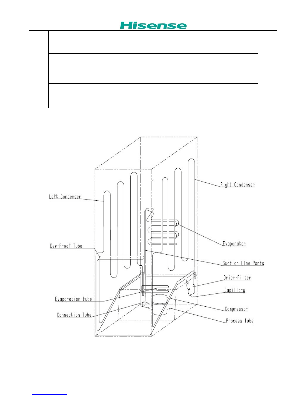
Cooling diagram ........................................................................................................................................................... 5
Fault display code ......................................................................................................................................................... 6
Compulsory defrost ...................................................................................................................................................... 7
The setting of control panel .......................................................................................................................................... 7
Checking the Compressor ............................................................................................................................................. 8
Checking the defrost fuse ........................................................................................................................................... 10
Checking the Heater ................................................................................................................................................... 10
The guide for Disassembly Common parts of Refrigerator ........................................................................................ 11
The instruction of replacing the main board. .............................................................................................................. 11
The instruction of of replacing lamp and display board ............................................................................................. 12
The instruction of of replacing fan motor. .................................................................................................................. 13
The instruction of replacing evaporator temperature sensor and temperature fuse and heater. .................................. 14
The instruction of replacing Door switch. .................................................................................................................. 15
The instruction of replacing PTC Starting relay and Overload protector. .................................................................. 16
The instruction of replacing electric wind gate. ......................................................................................................... 16
Reversing the door ...................................................................................................................................................... 17
Water Dispenser .......................................................................................................................................................... 20
Troubleshooting .......................................................................................................................................................... 22
The common problem judging method ...................................................................................................................... 22
The solution for the common problem. ...................................................................................................................... 23
Note: ........................................................................................................................................................................... 25
Page 3

2
Warnings and precautions for safety
Please observe the following safety precautions in order to use safely and correctly the refrigerator
and to prevent accident and danger during repair.
1. Be care of an electric shock. Disconnect power cord from wall outlet and wait for more than
three minutes before replacing PCB parts.
Shut off the power whenever replacing and repairing electric components.
2. When connecting power cord, please wait for more than five minutes after power cord was
disconnected from the wall outlet.
3. Please check if the power plug is pressed down by the refrigerator against the wall.
If the power plug was damaged, it may cause fire or electric shock.
4. If the wall outlet is over loaded, it may cause fire.
Please use its own individual electrical outlet for the refrigerator.
5. Please make sure the outlet is properly earthed, particularly in wet or damp area.
6. Use standard electrical components when replacing them.
7. Make sure the hook is correctly engaged.
Remove dust and foreign materials from the housing and connecting parts.
8. Do not fray, damage, machine, heavily bend, pull out or twist the power cord.
9. Please check the evidence of moisture intrusion in the electrical components.
Replace the parts or mask it with insulation tapes if moisture intrusion was confirmed.
10. Do not touch the icemaker with hands or tools to confirm the operation of geared motor.
11. Do not let the customers repair, disassemble and reconstruct the refrigerator for themselves.
It may cause accident, electric shock, or fire.
12. Do not store flammable materials such as ether, benzene, alcohol, chemicals, gas, or
medicine in the refrigerator.
13. Do not put flower vase, cup, cosmetics, chemicals, etc., or container with full of water
on the top of the refrigerator.
14. Do not put glass bottles with full of water into the freezer.
The contents shall freeze and break the glass bottles.
15. When you scrap the refrigerator, please disconnect the door gasket first and scrap it
Page 4

3
Parts Descr iption
Page 5

4
Circuit diagrams an d parameters
Basic features
Voltage / frequency v/Hz 220-240V~ 50HZ
Net capacity l RD-44WC
Net capacity fridge compartmen
(Fridge/Chill) l 229L
Net capacity freezer compartment
l 93L
Energy efficiency class
A+
Climate class (SN=10~32°C, N=16~32°C,
ST=16~38°C, T=16~43°C) SN-T
Freezer compartment star rating 4 Star
Energy consumption / year kWh/year 310
Energy consumption (ISIRI 4853-2) per 24 h kWh/24 h 0.85
Freezing capacity / 24 hours kg/24 h 12
Compressor (W) 220V,165W
PTC starter (V/Ω) 220V ,15±20%Ω
Overload protector (Turn off/Turn on) °C 120±5°C/ 61±9°C
Heater (V/W/Ω)
220V,150W±10%
324Ω±10%
Page 6
5
Cooling diagram
LED Light (V/W) DC12V,1W
fan motor (V/W) 13.2V,2W
Max noise level dB(A) ≤42
Kind of coolant / Charge (R134a/R600a) /
grammes R / g R600a/38.5
Net weight kg 77
Gross weight kg 85
W x D x H (appearance) mm 595×683×1850
W x D x H (packaging) mm 646×741×1931
Page 7

6
Fault displ ay code
1.If there is a temperature sensor f ault, fan fault or defrosting timeout fault, each time you open the refrigerator
door, t he cor r esponding LED light flashing 30 seconds on the display boar d.
2.When freezer temperatu r e sensor occur failure: refrigeration temperature display ar ea D1 Light flash 30
seconds.
3. When the freez er temper ature sensor occur fai lure: froz en temperat ure dis play area F 1 lights flash 30 seconds.
4. When the defrosting se nsor occur failure: frozen temperature display area F2 indicator light flash 30 seconds.
5. When the refrigerant evapor at ing fan occur failure: frozen temperatur e display area F3 indicator light f lash 30
seconds.
6. When the defrosting he at er heat ing time arrive to the limit ti me, frozen temperature disp lay area F4 indicator
light flash 30 seconds.
7. when the refrigerator door open time more than 2 minutes and less than 12 minutes, refri ger at or door
temperature display area D5 i ndicator lights indicat i ng unt il the refrigerator door clos ed.
8. when frozen door open time m or e t han 2 minutes and less than 12 minut es, the freezing temperature disp lay
area F5 indicator lights i ndicating until frozen door closed.
9. When communicati on occur failure refrigerat ion temperature display area D2 indicator lig hts indicating unti l the
communications back to nor m al.
When the fault is eliminated, it turns to norm al d isplay.
Using a multimeter with the ohm switch to measure the resist or of sensor, normally at surrounding 25 ℃ the
resistor should be about 2kohm and every with the temperature decreases 1℃ the corresponding resistor value
would increase about 45o hm. I f the measured value is not within the normal scope, the sensor i s bad and needs
to repair or change.
Page 8

7
Compulsory defrost
within 10 minutes after connecting power, please Press the button "Fridge" and "Freezer" at the s ame time, when
the refrigerator door opens and t he freezer door closes, for 10 seconds . In addition, w ith a long sound of buzzer,
it enters into the process of mandat or y defrosting.
--After entering into the process of mandatory defrosting, it controls the operation according to the normal
operation of the automatic defrosting process.
--In the process of mandatory defrosting, the cold storage and the frozen temperature display area LED lamp
repeatedly lights up from left to right.
The setting of control panel
Page 9

8
Checking the Compressor
Use a multi-meter to test the resistance between C & M, C&S and S&M :
Normal range of C&M : About 10-21Ω
Normal range of C&S : About 10-27Ω
Normal range of S&M : About 20-50Ω
If the test result is not in this range then it means the inner coil has some problem and the compressor can not
work properly.
Page 10

9
Compressor Protector test ——
Use a multi-meter to test the resistance between t he two end as the pic show :
If there show 000 or almost 0 then it is OK.
If there is no response then it is broken.
Compressor PTC start er t est ——
Use a multi-meter to test the resistance between the two end as t he pic show :
If there show the number is betw een About 9-25Ω then it is OK.
If there show 000 or no response then it is broken.
Page 11

10
Checking the defrost fuse
Fuse is a high temperature protector of defrost system, when defrosting, if it feel the temperature is more than
73℃, it will cut off the defrost heater, stopping defrost, so that it can protect the part s. The common problems are
evaporator defrost inco mp lete:
Checking method as following:
Picture 1 Picture 2
As picture 1,it is the defrost fus e.
As picture 2 , using the multim et er m easure two foots of fuse, if the value of resistance is 0000, it means normal.
Checking the Heater
If defrost system failure,checking the heater and the temperature fu se as well as wires.
Measuring temperature fuse and heater resistan ce about 324Ω then it is OK.( Brown and Blue)
Page 12

11
The guide for Disassembly Common parts of Refrigerator
The instruction of replacing the main boar d.
1. The location of the
electrical main board.
2. Unscrew electrical
box ( 2 screws ).
3. Remove the electrical
box.
4. Open the electrical
appliances lifted the lid
5. Unplug the electrical
wires.
Page 13

12
6. Unload the main
board screw
7. Remove the main
board
The instruction of of replacing lamp and display b oar d
1.The location of the
lamp.
2. With a screwdriver to
pry open lamp shade
card buckle.
3. Remove the lamp
cover.
4. By hand unload
display board
5.Remove the display
board
6.Unplug the electrical
wires.
Page 14

13
7.Remove display
board screw
8. Take out the
display board and led
light.
The instruction of of replacing fan motor.
1. The location of the
fan motor and remove
the freezer drawers.
2. Unscrew two screws
of the wind channel
part in freezer chamber.
3. Unplug the electrical
wires and remove the
fan motor part.
Page 15

14
4. Unscrew the f ixing
screws of the fan motor
and take out the fan
motor
The instruction of replacing evaporator temperature sensor and temperature fuse and
heater.
1.Take out the defrost
sensor.
2.Take out the
temperature fuse.
3. Remove
evaporator fixing
screws.
4. Take out the
evaporator.
Page 16

15
5.Use a screwdriver
or pliers to pry open
the receiving tank
retaining tabs
6.Take out the water
drain.
7.Use pliers to pry
open the heater fixed
buckle.
8. with a craft knife to
cut the Heater cable
fixing bolt.
9.Take out the heater.
The instruction of replacing Do or switch.
1. Open the upper
end cover.
2. Take out the door
switch
Page 17

16
1. Pry fixed cover
2. Take out the Fan
motor switch.
The instruction of replacing PTC Starting relay and Overload protector.
1. The location of the
PTC Starting relay and
Overload protector.
2. Disconnect the
connect ing wire of the
PTC Starting relay and
Overload protector.
The instruction of replacing ele ctric wind gate.
the electric wind gate of
The locat ion
Page 18

17
Reversing the door
Page 19

18
Page 20

19
Page 21

20
Water Dispenser
Page 22

21
Page 23

22
Troubleshooting
The common problem judging method
Problem Cause
Refrigerator can’t start
1.1 Is the power cord connect ing well?
1.2 Is the power voltage too low?
1.3 Is the sensor irrational sett ing?
1.4 Is the ambient temperature too low?
1.5 Is the circuit on power?
1.6 Is there some default in compressor
1.7 Is the refrigerat ion system blocked by ice or dirty, please stop the unit and restart after 10
minutes to see if the compressor can start.
Weak cooling effects
2.1 Is there any heat source around the refrigerator?
2.2 Is there enough space around the refrigerator for reject ion of heat?
2.3 Is the setting of the temperature appropriate?
2.4 Is there too much food or overheat ing food in it?
2.5 Does there open the door frequently?
2.6 Is the door completely closed?
2.7 Does the gasket destroyed or distort?
2.8 Does the gas leak?
The unit can not stop
running
3.1 Is there any heat source around the refrigerator?
3.2 Is there enough space around the refrigerator for reject ion of heat?
3.3 Is the setting of the temperature appropriate?
3.4 Is there too much food or overheat ing food in it?
3.5 Does there open the door frequently?
3.6 Is the door completely closed?
3.7 Does the gasket destroyed or distort?
3.8 Is the thermostat good operation?
3.9 Does the gas leak?
Ice up in the freezing
chamber
4.1 Is the sett ing of the temperature appropriate?
4.2 Is there multi-moisture food and too close to the back wall of the refrigerator?
4.3 Is the ambient temperature too low?
4.4 Is the electric parts on good condit ion, specially the thermostat wich will cause the unit
non-stopping .
Abnormal noise
5.1 Is the refrigerator stably placed?
5.2 Does the refrigerator bump other objects?
5.3 Whether the internal accessory of the refrigerator is in the right place.
5.4 Whether the water plate of compressor is fall from the unit.
5.5 Does the tube of the refrigerat ion system bump each other?
5.6 The noise sound likes Water flow inside the refrigerator ,in fact ,it is normal, which is caused
both when refrigerator start and shut-down; in addit ion, frost-dissolving causes this sound,
too, which is a normal phenomenon.
5.7 There will be a cracking sound in the cabinet ,when the cabinet or cabinet accessory
Page 24

23
contract ing or expanding, this sound will be made, which is normal.
5.8 The motor operation sound in the compressor is appears to be louder at night or begin
start ing. which is a normal phenomenon; also the uneven placing would lead to too much
running noise.
There is a peculiar
smell in the units
6.1 Is the food with special smell sealed t ight?
6.2 Does it have long time storing food or degenerated food?
6.3 Whether the internal cabinet needs cleaning.
the forefront or the
middle cabinet heats
7.1 As fridge Anti-condensat ion tube is placed here and caused the above phenomenon, which
is normal.
Refrigerator’s two sides
or the back heat
8.1 As condensation tube is placed here and caused the above phenomenon, which is normal.
the cabinet surface
condensat ion
9.1 Air humidity is too large.
The solution for the common pr oblem.
1.Cooling is not enough good
(Many reasons might cause that cooling not enough good, as blow )
Reason analysis Solutions
1) Leakage of Gas
If some gas leaked unit will work not well.
Phenomenon of failure:
a. lower pressure of liquid cycle system
b. high temperature of copper tube of
discharging gas, hand feels very hot.
C. much noise, sounds like “ZZZZZ”, comes
from outlet of capillary.
d. the temperature fell down very slowly.
First f ind out the point of leaking on
tube, and then sealed it, vacuuming
it, finally recharge with Gas.
Note:
If you find oil on somewhere, it is
possible that leakage point is there.
2) The quantity of Gas is
too much
If too much Gas was charged into the cycle
system, the extra gas will occupy some space
of evaporator, so that the area of heat
exchange becomes less, unit will work not well.
Phenomenon of failure:
a, higher pressure of liquid cycle system than
norm.
b, higher temperature of condenser.
c, larger electric current of compressor
d, there maybe ice on the suction tube.
e, when gas is too much, some gas liquid might
goes back into compressor, compressor will be
damaged by liquid.
First stop unit for several minutes,
and then open charging tube,
discharge all of gas. Change a new
filter, and then recharge gas, finally
sealed the system.
3) There is air in the
liquid cycle system
The air in system will cause lower efficiency of
cooling.
Phenomenon of failure:
a, higher pressure of liquid cycle system than
norm, but the pressure is not over the limit.
First stop unit for several minutes,
and then open charging tube,
discharge all of gas. Change a new
filter, and then recharge gas, finally
sealed the system.
Page 25

24
b, higher temperature of discharging tube.
C, much noise
4)Low working
efficiency of
compressor
General when a compressor works for many
years, some parts of compressor were wear, so
that compressor discharge less gas out, unit
does not work strongly.
Phenomenon of failure:
a, lower pressure of discharging, check the
pressure of system with pressure meter to see
if it is normal.
b, higher temperature of compressor surface.
C, cut off the discharging tube, to see if you can
block the gas coming out of the tube when
compressor is working.
Change a new compressor.
5
) There is something
that blocked the liquid
cycle system
Some time there is something blocked the
filter of liquid cycle system, so that unit is not
cold.
Phenomenon of failure:
a, lower pressure of discharging
b, lower temperature of discharging.
Change a new filter
2.NO COOL
(Popular failure reasons are below):
Reason analysis Solutions:
1) Leakage of gas
Phenomenon of failure:
a, leaking fast
b, leaking slowly
c, no voice of liquid flowing
d, cut off charging tube, no gas goes
out.
First f ind out the point of leaking on tube, and
then sealed it, vacuuming it, f inally recharge
with gas.
Note:
If you find oil on somewhere, it is possible that
leakage point is there.
2)There is some thing
that blocked the liquid
cycle system
A,Ice blocking
Sometime because unknown reason
water comes into liquid cycle
system, the capillary will be blocked
by water after unit runs for period of
time.
Phenomenon of failure:
The unit works well in the inception,
after period of time the ice appears
in the capillary and becomes more
and more, till blocks the hole of
capillary completely. In the moment
you can find the ice on the
evaporator defrosts. The noise of
liquid flow disappears. The pressure
First stop unit for several minutes, and then
open charging tube, discharge all of gas. Blow
the cycle system with gas of nitrogen, and then
recharge Gas, finally sealed the system.
Page 26

25
of absorbing becomes negat ive.
The phenomenon above will appear
again and again.
The way to check ice blocking:
Warm the capillary with a hot towel,
after a while the ice in the capillary
melt, you can hear a sound of gas
flow comes from the capillary
abruptly. The pressure of absorbing
becomes higher. It is Ice blocking.
B, there is offal block the capillary
Phenomenon of failure:
If the capillary is blocked by
something such as offal etc., the
sound of liquid flow disappears.
The ice on the evaporator defrosts
The pressure of absorbing becomes
negative.
Higher temperature of discharging
tube
The way to check offal blocking:
If you warm capillary with the way of
checking ice blocking, there is no
change. It must be offal blocking.
First stop unit for several minutes, and then
open charging tube, discharge all of gas. Blow
the cycle system with gas of nitrogen. Change
a new capillary and filter, and then recharge
Gas, finally sealed the system.
COMPRESSOR NEVER STOPS:
Reason Solutions
1)The sett ing temperature is not reasonable. Readjust the temperature sett ing.
2) the sensor is bad. Replace the sensor.
3)Seal of door is damaged. Replace the gasket
4)Too much food in the refrigerator Please put the food properly.
5)Wind door is broken. Replace wind door.
6)Fan motor is broken. Replace fan motor
Note:
● Before doing these operations above, disconnect the m ain pow er supply. Failure to do so could result in electrical
shock or personal injury.
● In c a s e o f a n y d e t a ile d t e c h n ic a l in fo r m a t io n p le a s e c h e c k w ith t h e technical specif ications.
 Loading...