

Page 1
1
Version: 1.1
Hisense Corporation
Page 2
2
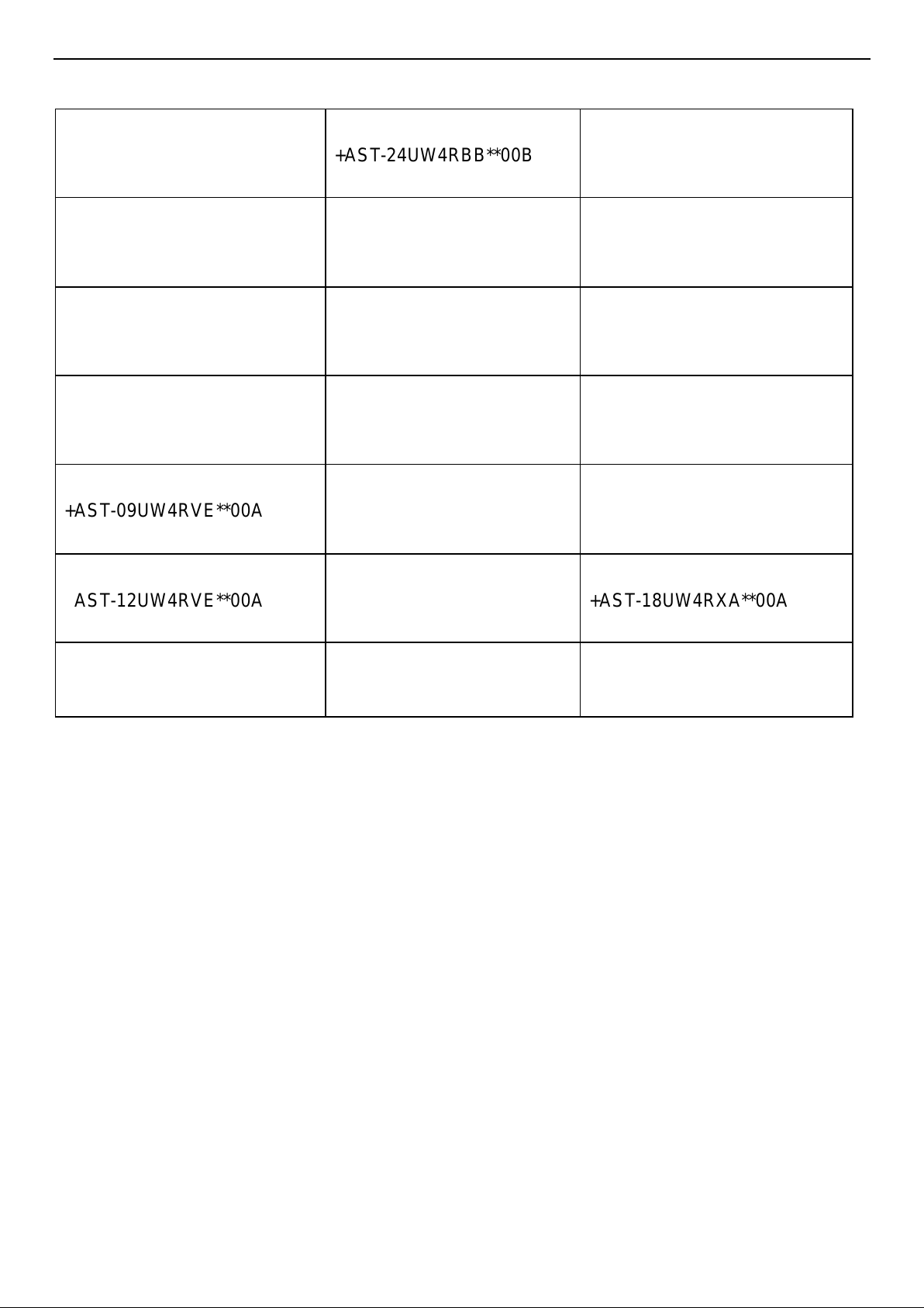
MODEL:
+AST-09UW4RXE**00B
+AST-24UW4RBB**00B
AST-18UW4RXS**01
+AST-12UW4RXE**00B
+AST-09UW4RVE**00
AST-24UW4RBT**01
+AST-18UW4RBA**00A
+AST-12UW4RVE**00
+AST-09UW4RXU**00
+AST-24UW4RDB**00A
+AST-18UW4RXA**00
+AST-12UW4RXU**00
+AST-09UW4RVE**00A
+AST-24UW4RBB**00
+AST-09UW4RXV**00
+AST-12UW4RVE**00A
AS-09UW4RYR**01A
+AST-18UW4RXA**00A
AS-12UW4RYR**01A
+AST-12UW4RXV**00
Note: “ ** ” mean code of Front Panel (See in 4-1 .Product Pictures).
Page 3
3
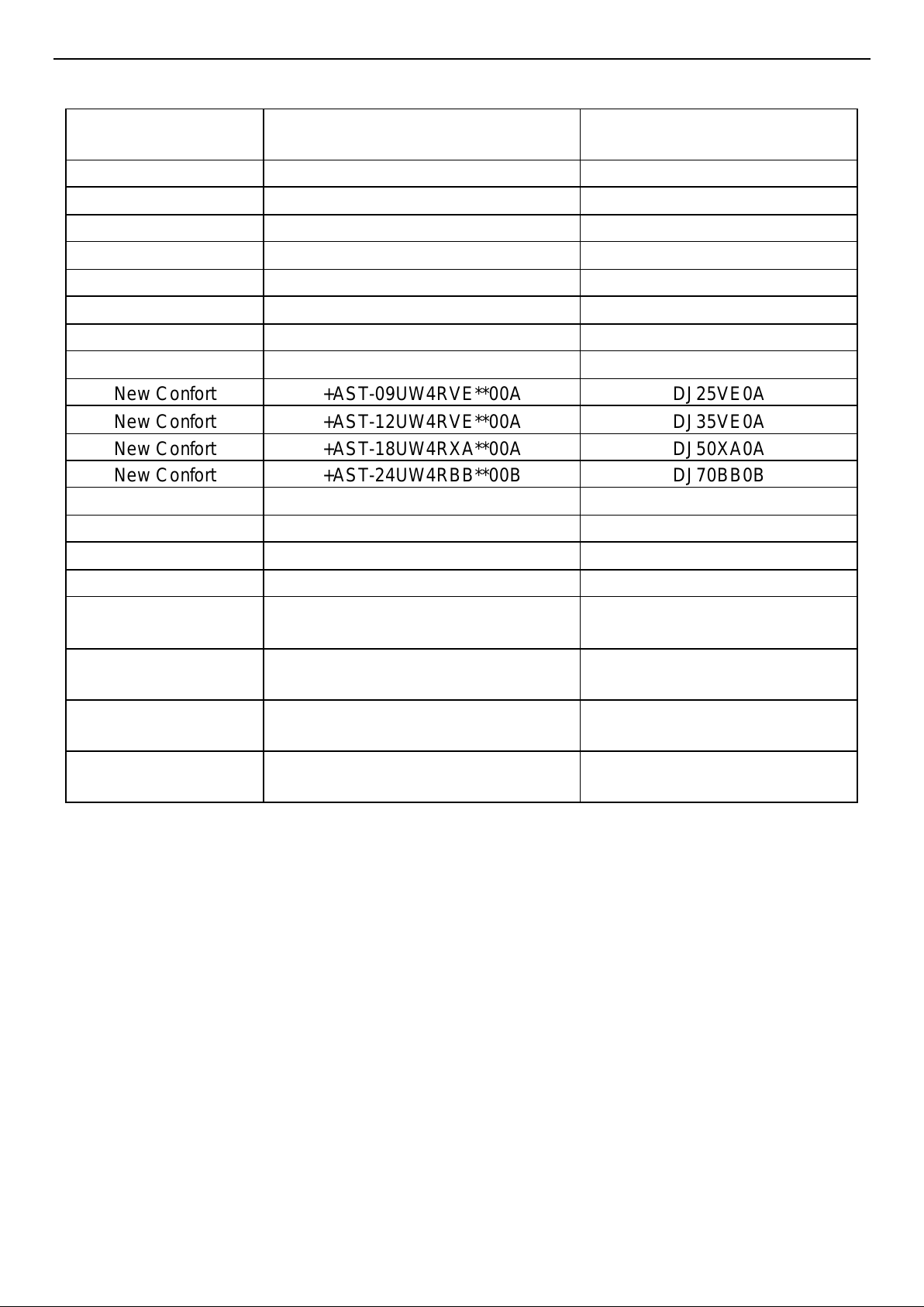
Model comparison table:
Category
Factory model
Model in
Set
Silentium Pro
+AST-09UW4RXU**00
QD25XU00
Silentium Pro
+AST-12UW4RXU**00
QD35XU00
Energy Pro
+AST-09UW4RXV**00
QE25XV00
Energy Pro
+AST-12UW4RXV**00
QE35XV00
Energy
+AST-09UW4RXE**00B
TQ25XE0C
Energy
+AST-12UW4RXE**00B
TQ35XE0C
Energy
+AST-18UW4RBA**00A
TQ50BA0B
Energy
+AST-24UW4RDB**00A
TQ70DB0B
New Confort
+AST-09UW4RVE**00A
DJ25VE0A
New Confort
+AST-12UW4RVE**00A
DJ35VE0A
New Confort
+AST-18UW4RXA**00A
DJ50XA0A
New Confort
+AST-24UW4RBB**00B
DJ70BB0B
Mini Apple Pie
+AST-09UW4RVE**00
TG25VE00
Mini Apple Pie
+AST-12UW4RVE**00
TG35VE00
Mini Apple Pie
+AST-18UW4RXA**00
TG50XA00
Mini Apple Pie
+AST-24UW4RBB**00
TG70BB00
Easy Smart/
Wings/Cozy
AS-09UW4RYR**01A
CA25YR1A/ KB25YR1A/
KG25YR1A
Easy Smart/
Wings/Cozy
AS-12UW4RYR**01A
CA35YR1A/ KB35YR1A/
KG35YR1A
Easy Smart/
Wings/Cozy
AST-18UW4RXS**01
CA50XS1A/ KB50XS1A/
KG50YR1A
Easy Smart/
Wings/Cozy
AST-24UW4RBT**01
CA70BT1A/ KB70BT1A/
KG70YR1A
Page 4

4
Contents
1. Safety Considerations ................................................................................................................................5
2. Product Specifications............................................................................................................................. 13
3. Name of Split type conditioner introduce ............................................................................................. 27
4. Pro duct Picture and Drawing ................................................................................................................ 28
4-1. Product Pictures ............................................................................................................................ 28
4-2. Product dimensions ...................................................................................................................... 31
5. Installation Instruction ............................................................................................................................. 35
5-1. Main Tools for Installation and Maintenance ............................................................................ 35
5-2. Installation Flow Diagram............................................................................................................. 36
5-3. Installation Place and Condition.................................................................................................. 37
5-4. Electric Wiring Diagram ................................................................................................................ 40
5-5. Refrigerant Flow System .............................................................................................................. 43
5-6. Air Purging and Leakage Test..................................................................................................... 44
5-7. Test Running .................................................................................................................................. 45
6. Function Operation .................................................................................................................................. 46
6-1. Operation Range (cooling and heating) .................................................................................. 46
6-2. Remote Controller Operation & Function .................................................................................. 47
6-3. Special Function Instruction ........................................................................................................ 56
6-4. Performance Data ......................................................................................................................... 57
7. Electrical Characteristics ........................................................................................................................ 59
7-1. Print Circuit Board (Indoor & Outdoor)....................................................................................... 59
7-2. Fan Motor ....................................................................................................................................... 66
7-3. Temperature Sensor ..................................................................................................................... 67
7-4. Compressor .................................................................................................................................... 71
7-5. Electric Reactor ............................................................................................................................. 71
7-6. Room Card Control, Fire Protection, ON/OFF Function (Optional) ...................................... 72
7-7. Wiring Remote Controller............................................................................................................. 79
8.Trouble S hooting ....................................................................................................................................... 80
8-1. Error Code Table ........................................................................................................................... 80
8-2. Test the jumper terminals ............................................................................................................ 92
8-3. Trouble Diagnosis of Protection .................................................................................................. 92
8-4. Trouble Diagnosis of Compressor .............................................................................................. 94
8-5. Trouble Diagnosis of Electric Filter Board ................................................................................. 94
8-6. Trouble Diagnosis of Electric Communication .......................................................................... 95
Page 5
5
8-7. Diagnosis and Solution................................................................................................................. 96
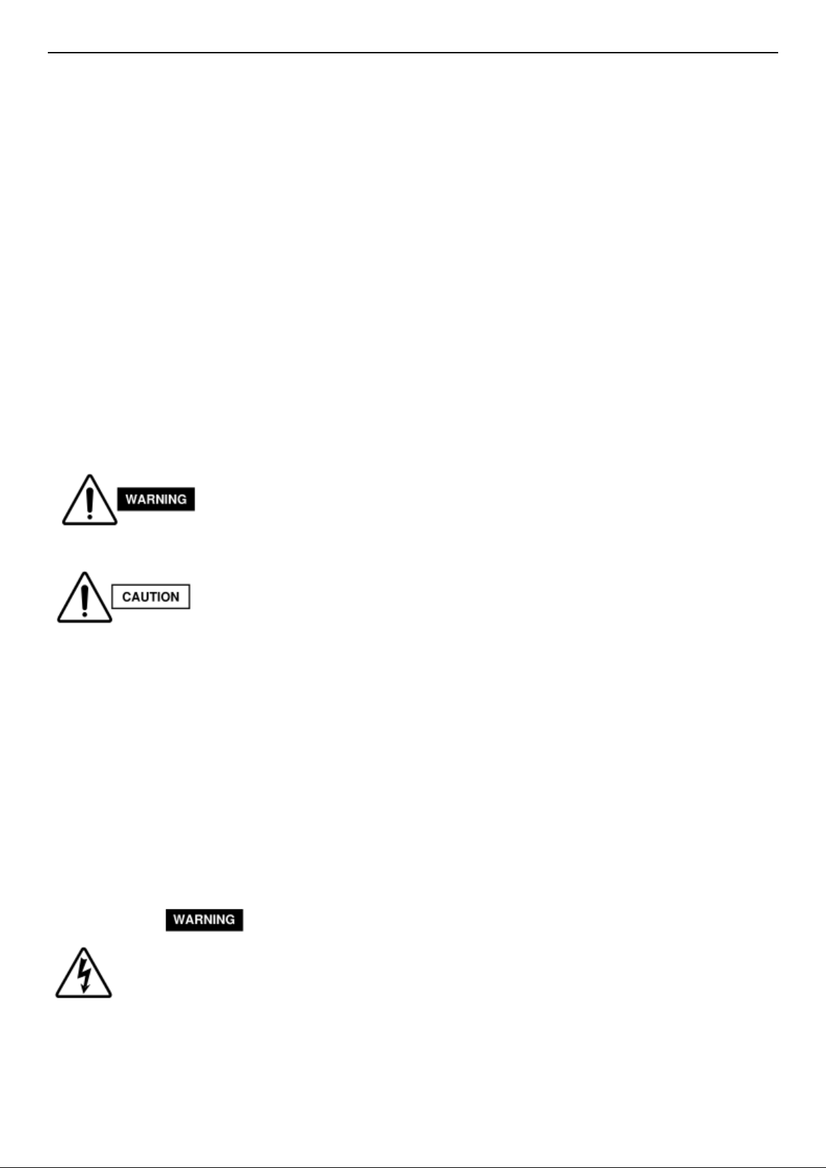
1. Safety Considerations
IMPORTANT!
Please Read Before Starting
This air conditioning system meets strict safety and operating standards. As the installer or service
person, it is an important part of your job to install or service the system, so it operates safely and
efficiently.
For safe installation and trouble-free operation, you must:
● Carefully read this instruction booklet before beginning.
● Follow each installation or repair step exactly as shown.
● Observe all local, state, and national electrical codes.
● Pay close attention to all warning and caution notices given in this manual.
This symbol refers to a hazard or unsafe practice which can result in severe
personal injury or death.
This symbol refers to a hazard or unsafe practice which can result in personal
injury or product or property damage.
If Necessary, Get Help
These instructions are all you need for most installation sites and maintenance conditions. If you
require help for a special problem, contact our sales/service outlet or your certified dealer for
additional instructions.
In Case of Improper Installation
The manufacturer shall in no way be responsible for improper installation or maintenance service,
including failure to follow the instructions in this document.
SPECIAL PRECAUTIONS
When Wiring
ELECTRICAL SHOCK CAN CAUSE SEVERE PERSONAL INJURY OR DEATH. ONLY A
QUALIFIED, EXPERIENCED ELECTRICIAN SHOULD ATTEMPT TO WIRE THIS SYSTEM.
● Do not supply power to the unit until all wiring and tubing are completed or reconnected and
checked.
● Highly dangerous electrical voltages are used in this system. Carefully refer to the wiring diagram
Page 6
6
and these instructions when wiring. Improper connections and inadequate grounding can cause
accidental injury or death.
● Ground the unit following local electrical codes.
● Connect all wiring tightly. Loose wiring may cause overheating at connection points and a possible
fire hazard.
When Transporting
Be careful when picking up and moving the indoor and outdoor units. Get a partner to help, and
bend your knees when lifting to reduce strain on your back. Sharp edges or thin aluminum fins on
the air conditioner can cut your fingers.
When Installing
● In a Ceiling or Wall
Make sure the ceiling/wall is strong enough to hold the unit’s weight. It may be necessary to
construct a strong wood or metal frame to provide added support.
● In a Room
Properly insulate any tubing run inside a room to prevent“sweating” that can cause dripping and
water damage to walls and floors.
● In Moist or Uneven Locations
Use a raised concrete pad or concrete blocks to provide a solid, level foundation for the outdoor
unit. This prevents water damage and abnormal vibration.
● In an Area with High Winds
Securely anchor the outdoor unit down with bolts and a metal frame. Provide a suitable air baffle.
● In a Snowy Area (for Heat Pump-type Systems)
Install the outdoor unit on a raised platform that is higher than drifting snow. Provide snow vents.
When Connecting Refrigerant Tubing
△ Use the flare method for connecting tubing.
△ Apply refrigerant lubricant to the matching surfaces of the flare and union tubes before connecting
them, then tighten the nut with a torque wrench for a leak free connection.
△ Check carefully for leaks before starting the test run.
When Servicing
△ Turn the power OFF at the main power box (mains) before opening the unit to check or repair
electrical parts and wiring.
△ Keep your fingers and clothing away from any moving parts.
△ Clean up the site after you finish, remembering to check that no metal scraps or bits of wiring
have been left inside the unit being serviced.
Others
△ Ventilate any enclosed areas when installing or testing the refrigeration system. Escaped
refrigerant gas, on contact with fire or heat, can produce dangerously toxic gas.
△ Confirm upon completing installation that no refrigerant gas is leaking. If escaped gas comes in
contact with a stove, gas water heater, electric room heater or other heat source, it can produce
dangerously toxic gas.
NOTE:
The figure、size and param eter of the product m ay not be identical with the service manual, please
take the actual product as the standard.
Page 7

7
Precautions for using R32 refrigerant
The basic installation work procedures are the same as the conventional refrigerant
(R22 or R410A). However, pay attention to the following points:
1. Transport of equipment containing flammable refrigerants Compliance with the transport
regulations
2. Marking of equipment using signs Compliance with local regulations
3. Disposal of equipment using flammable refrigerants Compliance with national regulations
4. Storage of equipment/appliances The storage of equipment should be in accordance with the
manufacturer's instructions.
5. Storage of packed (unsold) equipment Storage package protection should be constructed such
that mechanical damage to the equipment inside the package will not cause a leak of the
refrigerant charge.
The maximum number of pieces of equipment permitted to be stored together will be
determined by local regulations.
6. Information on servicing
6-1 Checks to the area
Prior to beginning work on systems containing flammable refrigerants, safety checks are
necessary to ensure that the risk of ignition is minimized. For repair to the refrigerating system, the
following precautions shall be complied with prior to conducting work on the system.
6-2 Work procedure
Work shall be undertaken under a controlled procedure so as to minimize the risk of flammab le
gas or vapour being present while the work is being performed.
6-3 General work area
All maintenance staff and others working in the local area shall be instructed on the nature of
work being carried out. Work in confined spaces shall be avoided.
The area around the workspace shall be sectioned off. Ensure that the conditions within the
area have been made safe by control of flammable material.
6-4 Checking for presence of refrigerant
The area shall be checked with an appropriate refrigerant detector prior to and during work, to
ensure the technician is aware of potentially flammable atmospheres.
Ensure that the leak detection equipment being used is suitable for use with flammable
refrigerants, i.e. non-sparking, adequately sealed or intrinsically safe.
6-5 Presence of fire extinguisher
If any hot work is to be conducted on the refrigeration equipment or any associated parts,
appropriate fire extinguishing equipment shall be available to hand.
Have a dry powder or CO2 fire extinguisher adjacent to the charging area.
6-6 No ignition sources
No person carrying out work in relation to a refrigeration system which involves exposing any
pipe work that contains or has contained flammable refrigerant shall use any sources of ignition in
such a manner that it may lead to the risk of fire or explosion.
All possible ignition sources, including cigarette smoking, should be kept sufficiently far away
from the site of installation, repairing, removing and disposal, during which flammable refrigerant
can possibly be released to the surrounding space.
Prior to work taking place, the area around the equipment is to be surveyed to make sure that
there are no flammable hazards or ignition risks. “No Smoking” signs shall be displayed.
6-7 Ventilated area
Ensure that the area is in the open or that it is adequately ventilated before breaking into the
system or conducting any hot work.
Page 8

8
A degree of ventilation shall continue during the period that the work is carried out.
The ventilation should safely disperse any released refrigerant and preferably expel it externally
into the atmosphere.
6-8 Checks to the refrigeration equipment
Where electrical components are being changed, they shall be fit for the purpose and to the
correct specification.
At all times the manufacturer's maintenance and service guidelines shall be followed. If in
doubt consult the manufacturer's technical department for assistance.
The following checks shall be applied to installations using flammable refrigerants:
– The charge size is in accordance with the room size within which the refrigerant containing
parts are installed;
– The ventilation machinery and outlets are operating adequately and are not obstructed;
– If an indirect refrigerating circuit is being used, the secondary circuit shall be checked for the
presence of refrigerant;
– Marking to the equipment continues to be visible and legible. Markings and signs that are
illegible shall be corrected;
– Refrigeration pipe or components are installed in a position where they are unlikely to be
exposed to any substance which may corrode refrigerant containing components, unless the
components are constructed of materials which are inherently resistant to being corroded or are
suitably protected against being so corroded.
6-9 Checks to electrical devices
Repair and maintenance to electrical components shall include initial safety checks and
component inspection procedures.
If a fault exists that could compromise safety, then no electrical supply shall be connected to
the circuit until it is satisfactorily dealt with.
If the fault cannot be corrected immediately but it is necessary to continue operation, an
adequate temporary solution shall be used.
This shall be reported to the owner of the equipment so all parties are advised. Initial safety
checks shall include:
– That capacitors are discharged: this shall be done in a safe manner to avoid possibility of
sparking;
– That there no live electrical components and wiring are exposed while charging, recovering or
purging the system;
– That there is continuity of earth bonding.
7. Repairs to sealed components
During repairs to sealed components, all electrical supplies shall be disconnected from the
equipment being worked upon prior to any removal of sealed covers, etc.
If it is absolutely necessary to have an electrical supply to equipment during servicing, then a
permanently operating form of leak detection shall be located at the most critical point to warn of
a potentially hazardous situation.
Particular attention shall be paid to the following to ensure that by working on electrical
components, the casing is not altered in such a way that the level of protection is affected.
This shall include damage to cables, excessive number of connections, terminals not made to
original specification, damage to seals, incorrect fitting of glands, etc.
Ensure that apparatus is mounted securely.
Ensure that seals or sealing materials have not degraded such that they no longer serve the
purpose of preventing the ingress of flammable atmospheres.
Replacement parts shall be in accordance with the manufacturer's specifications.
Page 9

9
NOTE:
The use of silicon sealant may inhibit the effectiveness of some types of leak detection
equipment. Intrinsically safe components do not have to be isolated prior to working on them.
8. Repair to intrinsically safe components
Do not apply any permanent inductive or capacitance loads to the circuit without ensuring that
this will not exceed the permissible voltage and current permitted for the equipment in use.
Intrinsically safe components are the only types that can be worked on while live in the
presence of a flammable atmosphere. The test apparatus shall be at the correct rating.
Replace components only with parts specified by the manufacturer.
Other parts may result in the ignition of refrigerant in the atmosphere from a leak.
9. Cabling
Check that cabling will not be subject to wear, corrosion, excessive pressure, vibration, sharp
edges or any other adverse environmental effects.
The check shall also take into account the effects of aging or continual vibration from sources
such as compressors or fans.
10.Detection of flammable refrigerants
Under no circumstances shall potential sources of ignition be used in the searching for or
detection of refrigerant leaks.
A halide torch (or any other detector using a naked flame) shall not be used.
11.Leak detection methods
The following leak detection methods are deemed acceptable for systems containing flammab le
refrigerants:
– Electronic leak detectors shall be used to detect flammable refrigerants, but the sensitivity may
not be adequate, or may need re-calibration. (Detection equipment shall be calibrated in a
refrigerant-free area.)
– Ensure that the detector is not a potential source of ignition and is suitable for the refrigerant
used.
– Leak detection equipment shall be set at a percentage of the LFL of the refrigerant and shall
be calibrated to the refrigerant employed and the appropriate percentage of gas (25 % maximu m)
is confirmed.
– Leak detection fluids are suitable for use with most refrigerants but the use of detergents
containing chlorine shall be avoided as the chlorine may react with the refrigerant and corrode the
copper pipe-work.
– If a leak is suspected, all naked flames shall be removed/ extinguished.
– If a leakage of refrigerant is found which requires brazing, all of the refrigerant shall be
recovered from the system, or isolated (by means of shut off valves) in a part of the system remote
from the leak.
– Oxygen free nitrogen (OFN) shall then be purged through the system both before and during
the brazing process.
12.Removal and evacuation
When breaking into the refrigerant circuit to make repairs – or for any other purpose –
conventional procedures shall be used.
However, it is important that best practice is followed since flammability is a consideration.
The following procedure shall be adhered to:
– Remove refrigerant;
– Purge the circuit with inert gas;
– Evacuate;
Page 10

10
– Purge again with inert gas;
– Open the circuit by cutting or brazing.
The refrigerant charge shall be recovered into the correct recovery cylinders.
The system shall be “flushed” with OFN to render the unit safe.
This process may need to be repeated several times.
Compressed air or oxygen shall not be used for this task.
Flushing shall be achieved by breaking the vacuum in the system with OFN and continuing to
fill until the working pressure is achieved, then venting to
atmosphere, and finally pulling down to a vacuum.
This process shall be repeated until no refrigerant is within the system. When the final OFN
charge is used, the system shall be vented down to atmospheric
pressure to enable work to take place.
This operation is absolutely vital if brazing operations on the pipe-work are to take place.
Ensure that the outlet for the vacuum pump is not close to any ignition sources and there is
ventilation available.
13.Charging procedures
In addition to conventional charging procedures, the following requirements shall be followed:
– Ensure that contamination of different refrigerants does not occur when using charging
equipment.
– Hoses or lines shall be as short as possible to minimise the amount of refrigerant contained in
them.
– Cylinders shall be kept upright.
– Ensure that the refrigeration system is earthed prior to charging the system with refrigerant.
– Label the system when charging is complete (if not already).
– Extreme care shall be taken not to overfill the refrigeration system.
Prior to recharging the system it shall be pressure tested with OFN.
The system shall be leak tested on completion of charging but prior to commissioning.
A follow up leak test shall be carried out prior to leaving the site.
14.Decommissioning
Before carrying out this procedure, it is essential that the technician is completely familiar with
the equipment and all its detail.
It is recommended good practice that all refrigerants are recovered safely.
Prior to the task being carried out, an oil and refrigerant sample shall be taken in case analysis
is required prior to re-use of reclaimed refrigerant. It is essential
that electrical power is available before the task is commenced.
a) Become familiar with the equipment and its operation.
b) Isolate system electrically.
c) Before attempting the procedure ensure that:
– Mechanical handling equipment is available, if required, for handling refrigerant cylinders;
– All personal protective equipment is available and being used correctly;
– The recovery process is supervised at all times by a competent person;
– Recovery equipment and cylinders conform to the appropriate standards.
d) Pump down refrigerant system, if possible.
e) If a vacuum is not possible, make a manifold so that refrigerant can be removed from various
parts of the system.
f) Make sure that cylinder is situated on the scales before recovery takes place.
g) Start the recovery machine and operate in accordance with manufacturer's
instructions.
Page 11

11
h) Do not overfill cylinders. (No more than 80 % volume liquid charge).
I ) Do not exceed the maximum working pressure of the cylinder, even temporarily.
j ) When the cylinders have been filled correctly and the process completed, make sure that
the cylinders and the equipment are removed from site promptly and all isolation valves on the
equipment are closed off.
k) Recovered refrigerant shall not be charged into another refrigeration system unless it has
been cleaned and checked.
15.Labelling
Equipment shall be labelled stating that it has been de-commissioned and emptied of
refrigerant.
The label shall be dated and signed.
Ensure that there are labels on the equipment stating the equipment contains flammable
refrigerant.
16.Recovery
When removing refrigerant from a system, either for servicing or decommissioning, it is
recommended good practice that all refrigerants are removed safely.
When transferring refrigerant into cylinders, ensure that only appropriate refrigerant recovery
cylinders are employed.
Ensure that the correct number of cylinders for holding the total system charge is available.
All cylinders to be used are designated for the recovered refrigerant and labelled for that
refrigerant (i.e. special cylinders for the recovery of refrigerant).
Cylinders shall be complete with pressure relief valve and associated shut -off valves in good
working order.
Empty recovery cylinders are evacuated and, if possible, cooled before recovery occurs.
The recovery equipment shall be in good working order with a set of instructions concerning
the equipment that is at hand and shall be suitable for the recovery of flammable refrigerants.
In addition, a set of calibrated weighing scales shall be available and in good working order.
Hoses shall be complete with leak-free disconnect couplings and in good condition.
Before using the recovery machine, check that it is in satisfactory working order, has been
properly maintained and that any associated electrical components are sealed to prevent ignition in
the event of a refrigerant release.
Consult manufacturer if in doubt.
The recovered refrigerant shall be returned to the refrigerant supplier in the correct recovery
cylinder, and the relevant Waste Transfer Note arranged.
Do not mix refrigerants in recovery units and especially not in cylinders.
If compressors or compressor oils are to be removed, ensure that they have been evacuated
to an acceptable level to make certain that flammable refrigerant does not remain within the
lubricant.
The evacuation process shall be carried out prior to returning the compressor to the suppliers.
Only electric heating to the compressor body shall be employed to accelerate this process.
When oil is drained from a system, it shall be carried out safely.
When moving or relocating the air conditioner, consult experienced service technicians for
disconnection and reinstallation of the unit.
Do not place any other electrical products or household belongings under indoor unit or outdoor
unit. Condensation dripping from the unit might get them wet, and may cause damage or
malfunction of your property.
Do not use means to accelerate the defrosting process or to clean, other than those
recommended by the manufacturer.
Page 12
12
The appliance shall be stored in a room without continuously operating ignition sources(for
example, open flames, an operating gas appliance or an operating electric heater).
Do not pierce or burn.
Be aware that refrigerants may not contain an odor.
To keep ventilation openings clear of obstruction.
The appliance shall be stored in a well-ventilated area where the room size
corresponds to the room area as specified for operation.
The appliance shall be stored in a room without continuously operating open flames (for
example an operating gas appliance) and ignition sources (for example an operating electric heater).
Any person who is involved with working on or breaking into a refrigerant circuit should hold a
current valid certificate from an industry-accredited assessment authority, which authorized their
competence to handle refrigerants safely in accordance with an industry recognized assessment
specification.
Servicing shall only be performed as recommended by the equipment manufacturer.
Maintenance and repair requiring the assistance of other skilled personnel shall be carried out
under the supervision of the person competent in the use of flammable refrigerants.
Do not use means to accelerate the defrosting process or to clean, other than those
recommended by the manufacturer.
Appliance shall be installed, operated and stored in a room with a floor area larger than 10
m2.
The installation of pipe-work shall be kept to a room with a floor area larger than 10 m2.
The pipe-work shall be compliance with national gas regulations. The maximum refrigerant
charge amount is 2.5 kg.
Mechanical connectors used indoors shall comply with ISO 14903. When mechanical
connectors are reused indoors, sealing parts shall be renewed.
When flared joints are reused indoors, the flare part shall be re-fabricated.
The installation of pipe-work shall be kept to a minimum.
Mechanical connections shall be accessible for maintenance purposes.
The indoor unit shall only be connected to outdoor units suitable for the same refrigerant.
The unit is a partial unit air conditioner, complying with partial unit requirements of the
International Standard, and must only be connected to other units that have been confirmed as
complying to corresponding partial unit requirements.
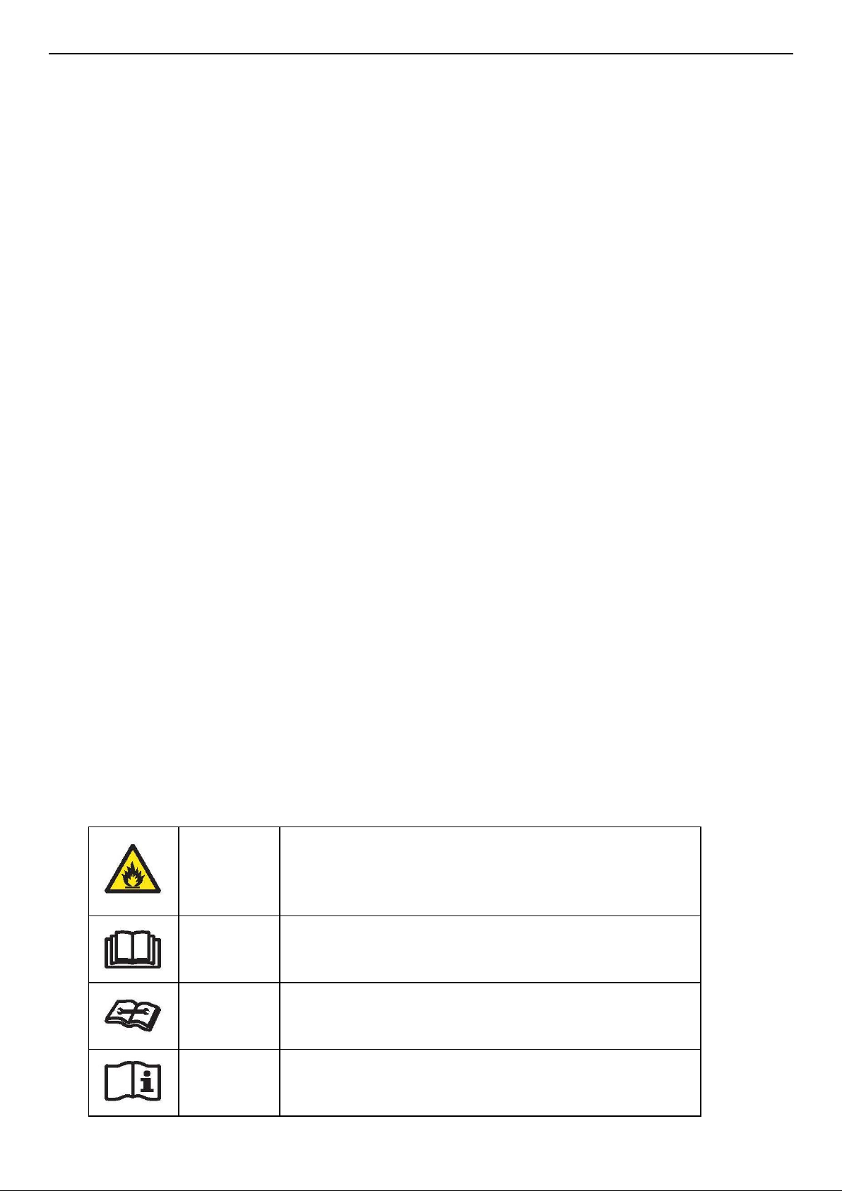
Explanation of symbols displayed on the indoor unit or outdoor unit.
WARNING
This symbol shows that this appliance uses a
flammable refrigerant.
If the refrigerant is leaked and exposed to an external
ignition source, there is a risk of fire.
CAUTION
This symbol shows that the operation manual should
be read carefully.
CAUTION
This symbol shows that a service personnel should be
handling this equipment with reference to the
installation manual.
CAUTION
This symbol shows that information is available such
as
the operating manual or installation manual.
Page 13
13
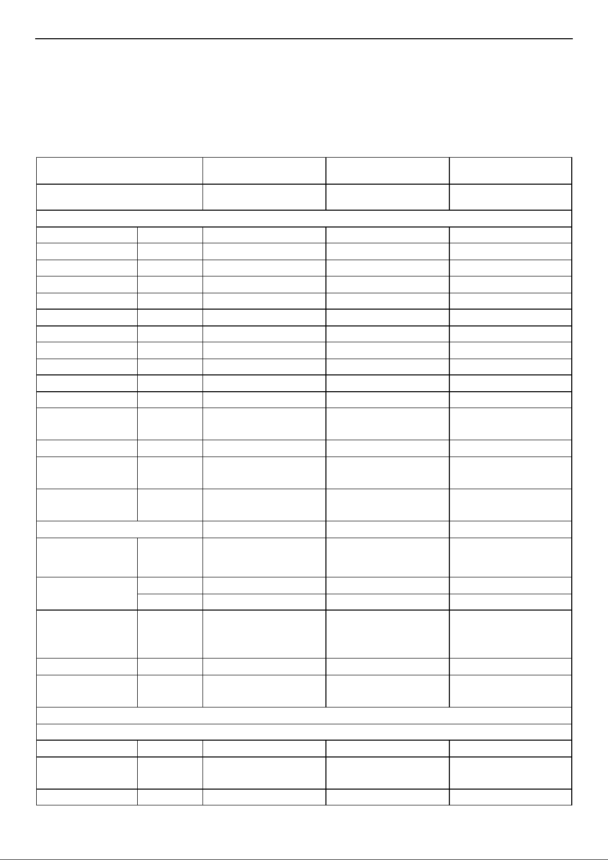
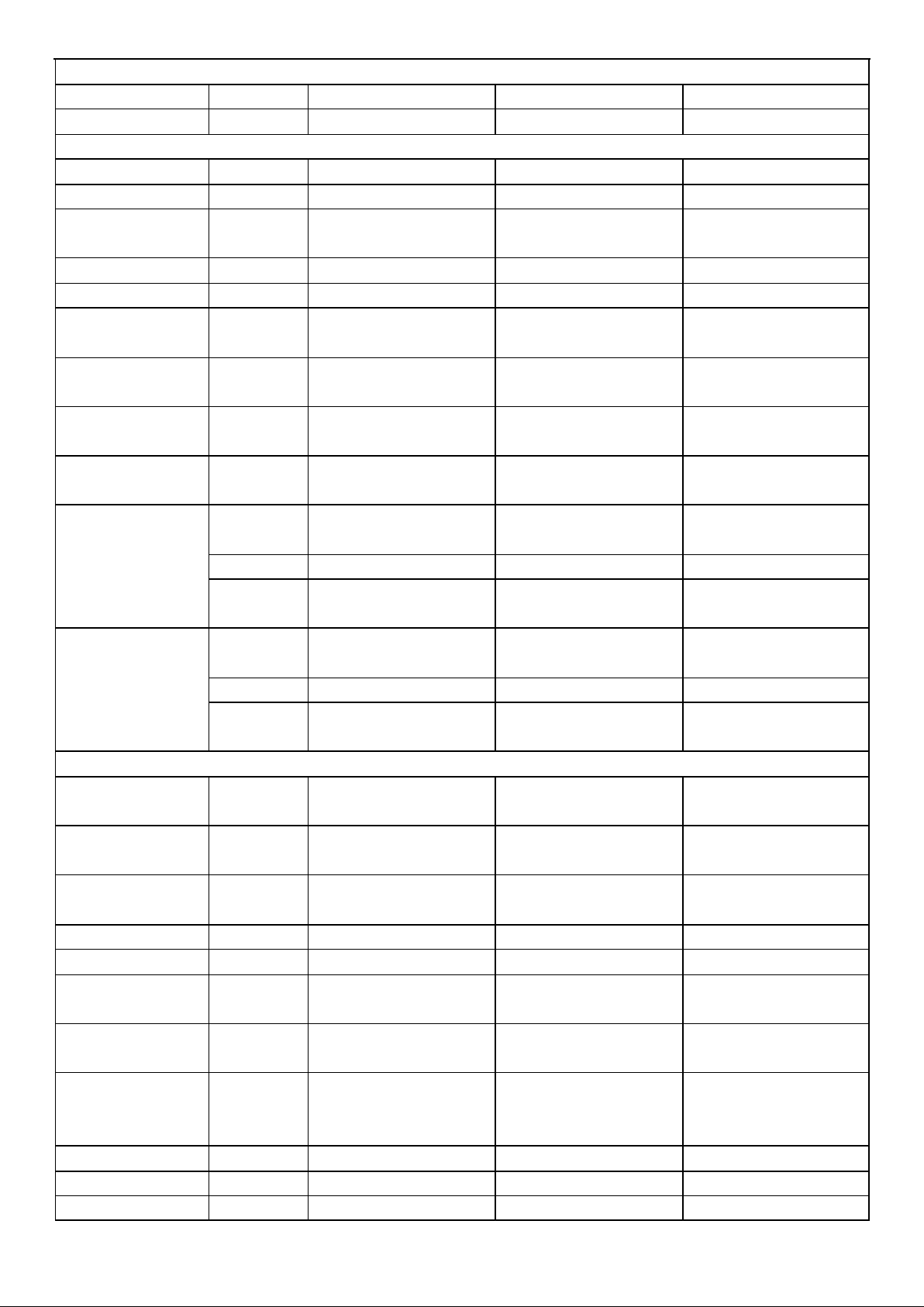
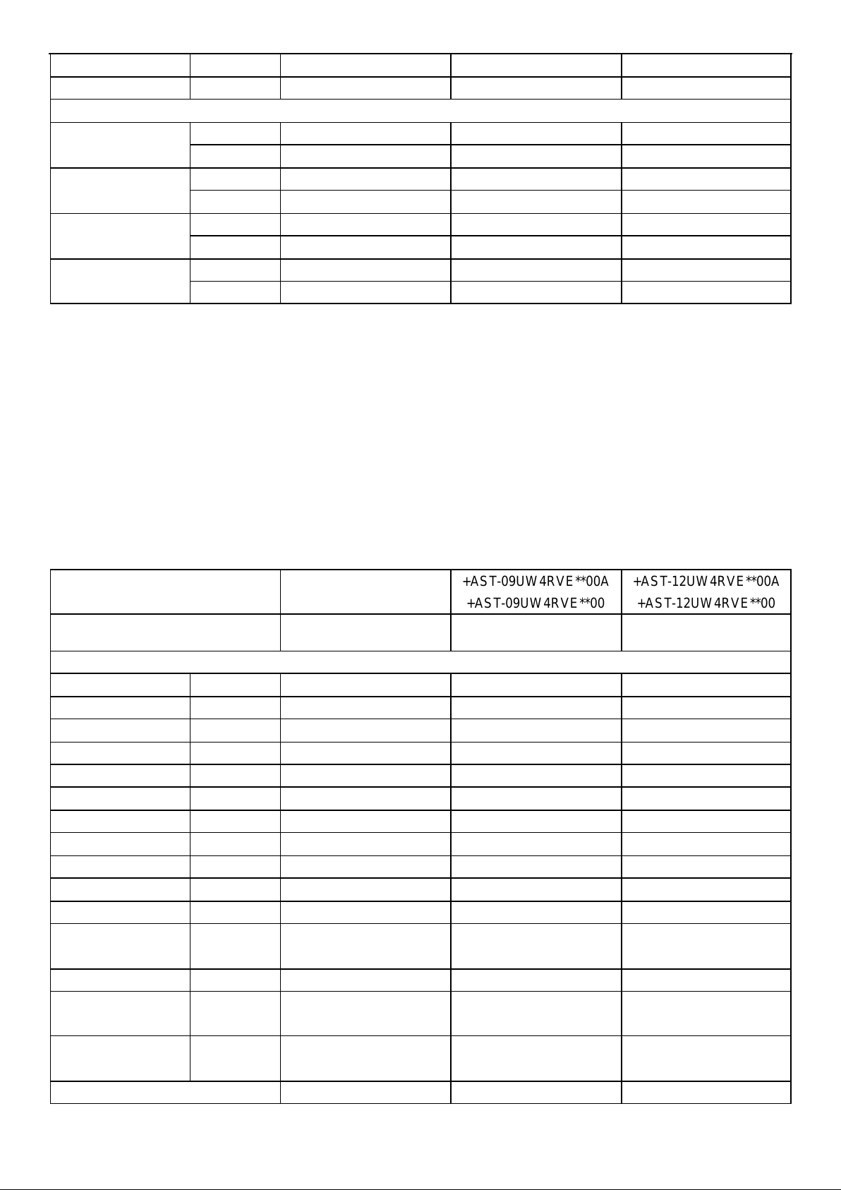
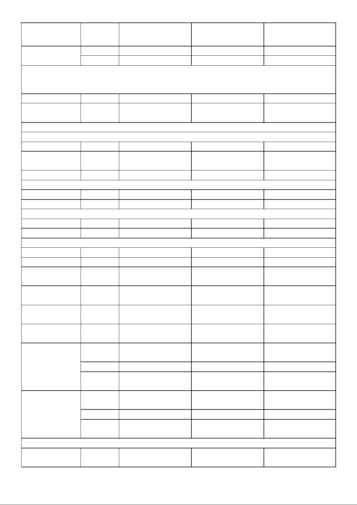
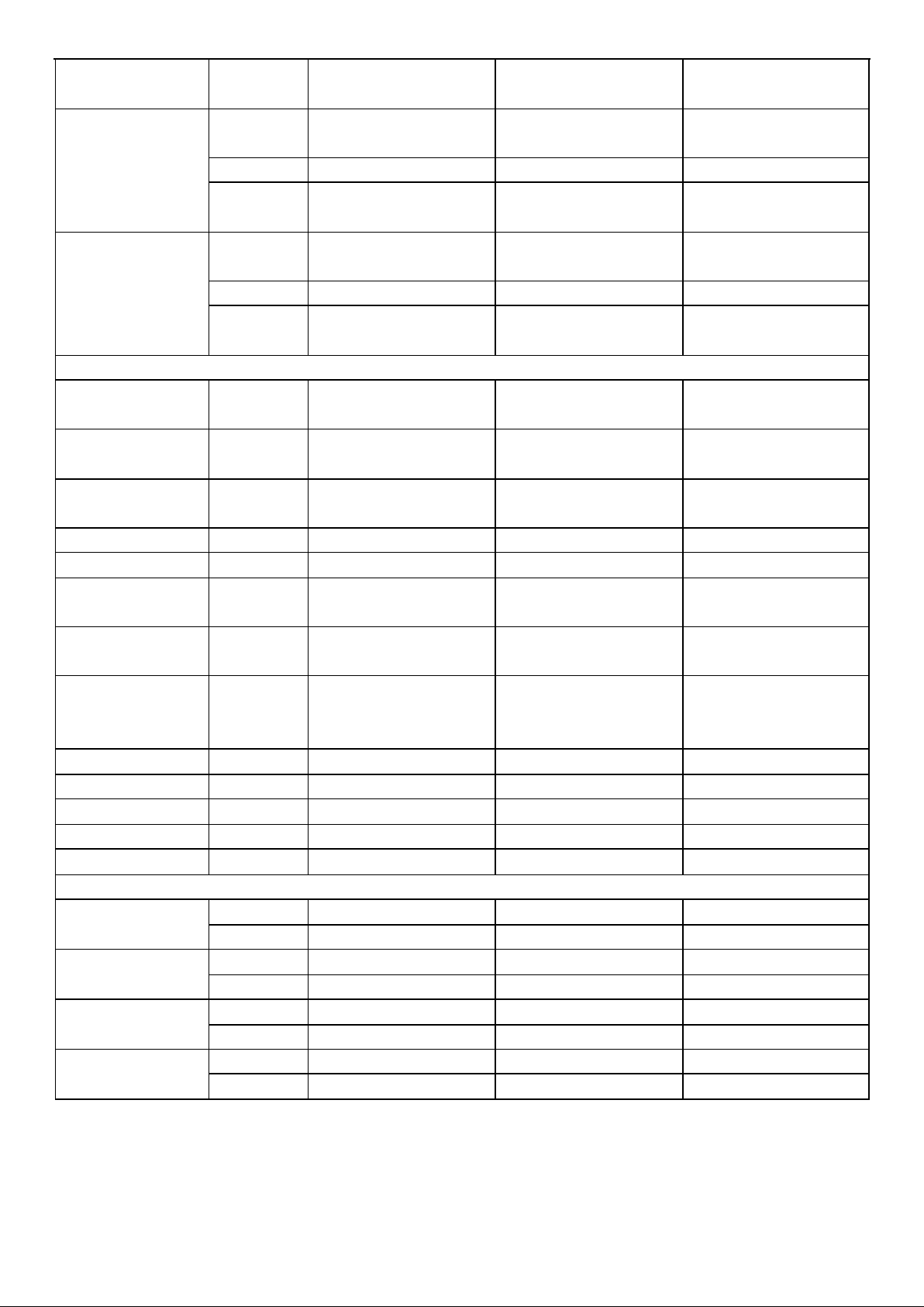
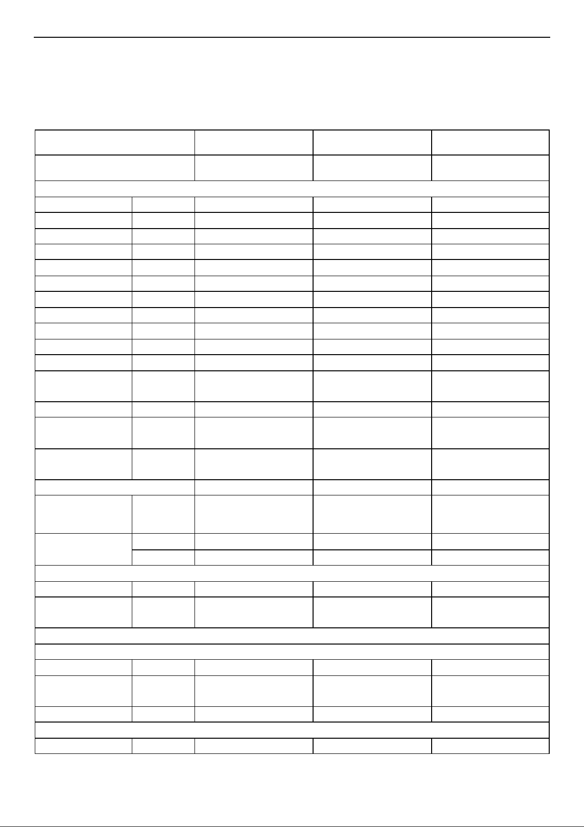
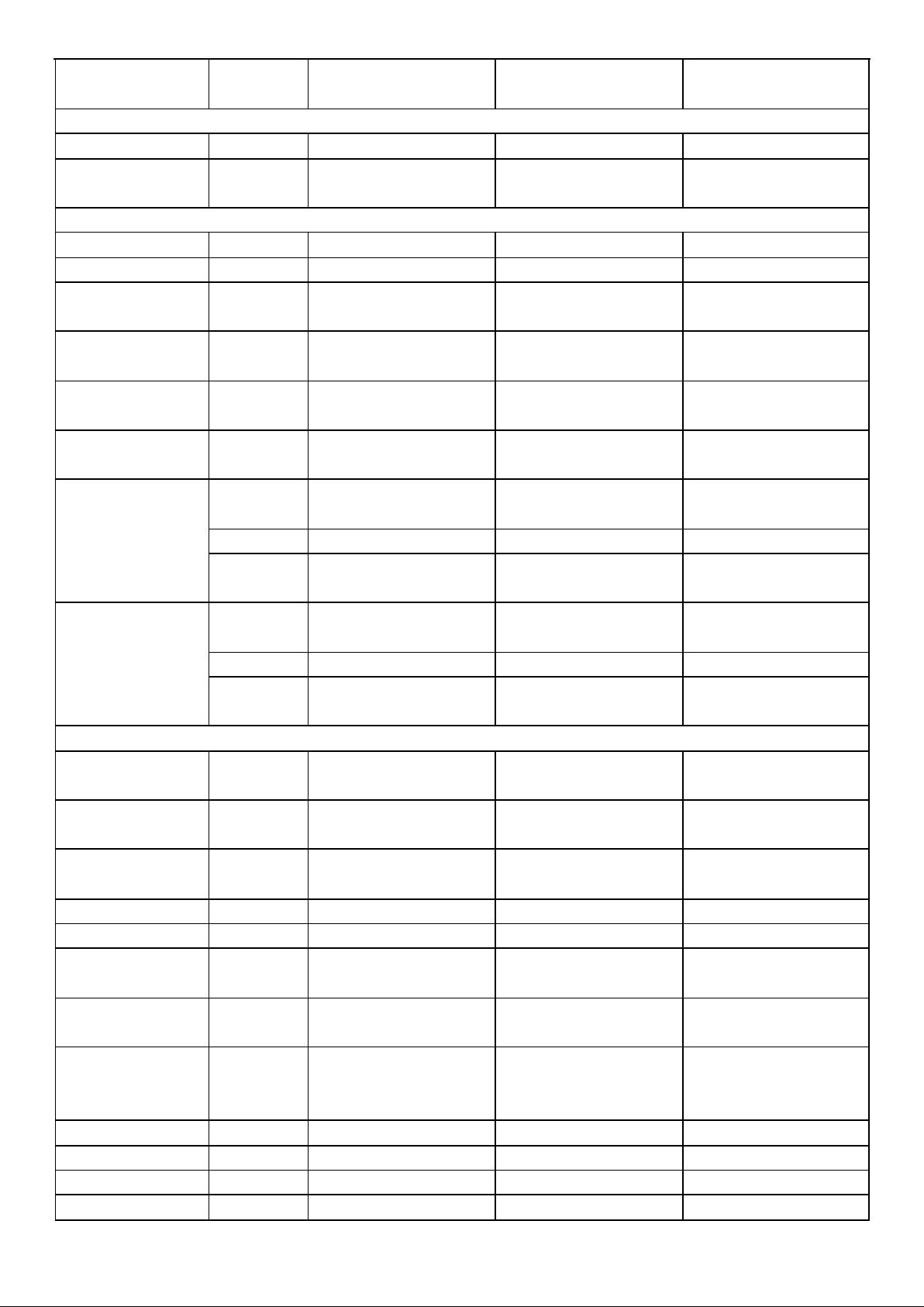
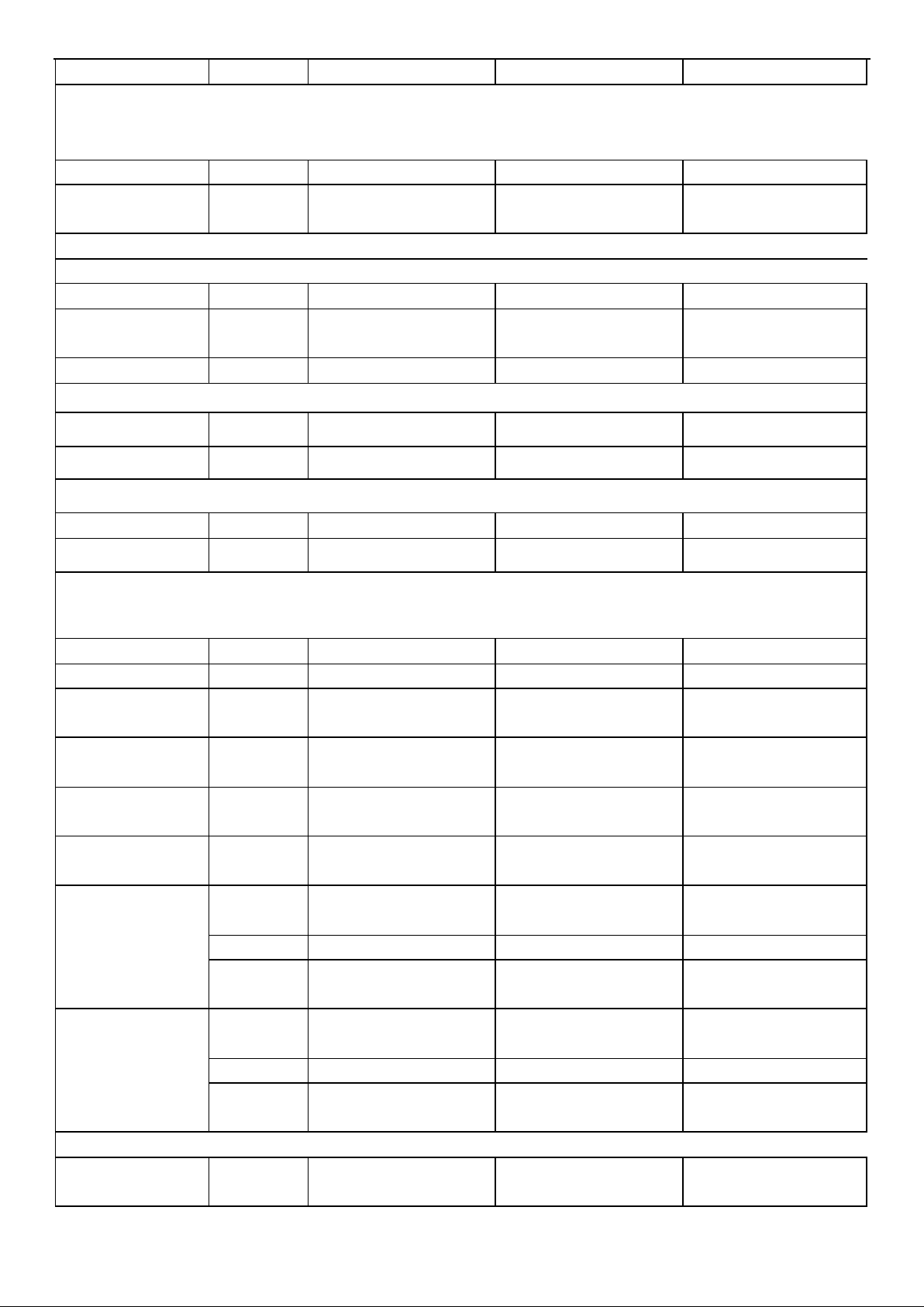
2. Product Specifications
Note: “**” mean code of Front Panel(relate pictures can check in content 4- 1).
Model No.
+AST-09UW4RXE**00B
+AST-12UW4RXE**00B
+AST-18UW4RBA**00A
Type
T1, H/P, INVERTER
T1, H/P, INVERTER
T1, H/P, INVERTER
Ratings
Cooling Capacity
W
2600
3500/3500
5000/5000
Heating Capacity
W
3000
4100/3200
5600/4000
Rated Input-Cooling
W
550
795
1280
Rated Input-Heating
W
715
1050
1400
Moisture Removal
L/h
0.9
1.2
2
Air Circulation
High m3/h
600
620
1000
EER for Cooling
W/W
8.5
4.4/8.5
3.90/8.1
COP for Heating
W/W
4.6
3.9/4.6
4.0/4.6
Energy Class
Cooling
A+++
A+++
A++
Energy Class
Heating
A++
A++
A++
Refrigerant
R32
R32
R32
Refrigerant charge
volume (5M)
g
910
1030
1220
Additional ref. Volume
g
20
20
20
Indoor Unit Noise
Level
High(dB (A))
56
56
60
Outdoor Unit Noise
Level
dB (A)
60
62
65
Power Supply
Voltage, Frequency,
Phase
V
220~240V,50Hz,1P
220-240V~,50Hz,1P
220~240V,50Hz,1P
Rated Current
Cooling (A)
2.5
3.5
5.7
Heating (A)
3.2
4.6
6.3
System pressures in
cooling rated
conditions
Max suction pressure
MPa
1.6
1.6
1.6
Max discharge
pressure
MPa
4.15
4.15
4.15
System
Compressor
Compressor type
/
Rotary
Rotary
Rotary
Compressor Model
No.
/
KSM98D32ULZ
KSM98D32ULZ
GTD130UKQA8JT6
Compressor MFG
/
GMCC
GMCC
Hitachi
Page 14
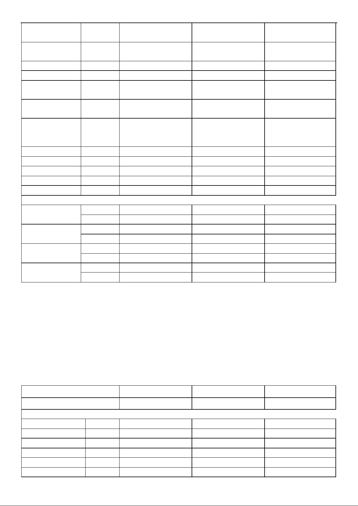
14
Indoor fan motor
Model No. / ZWA108D42B
ZWA108D42B
K1B310496
Brand / WOLONG
WOLONG
WOLONG
outdoor fan motor
Model / ZWA228D44B
ZWA228D44B
DG13Z2D-04
Brand / WOLONG
WOLONG
Broad-ocean
Connecting Pipe
Diameter
/
Liquid Pipe
inch
1/4
1/4
1/4
Gas Pipe
inch
3/8
3/8
1/2
Cooling Setting
Temperature Range
℃
16~30
16~30
16~30
Heating Setting
Temperature Range
℃
16~30
16~30
16~30
Cooling Operating
Temperature Range
℃
-15~43
-15~43
-15~43
Heating Operating
Temperature Range
℃
-15~24
-15~24
-15~24
Cooling speed
High
(r/min)
1100
1150
1150
Mid(r/min)
940
1000
990
Low
(r/min)
800
870
830
Heating speed
High
(r/min)
1100
1150
1150
Mid(r/min)
940
1000
990
Low
(r/min)
800
870
830
Features
Display on Front
Panel
/
LED
LED
LED
LCD Wireless
Remote Controller
/
Yes
Yes
Yes
Removable and
washable Panel
/
Yes
Yes
Yes
Washable PP Filter
/
Yes
Yes
Yes
24 Hours Timer / Yes
Yes
Yes
3 Speed and Auto
Indoor Fan Control
/
Yes
Yes
Yes
Vertical Auto Swing
Louver
/
Yes
Yes
Yes
Manual Adjustable
Horizontal Swing
Louver
/
Yes
Yes
Yes
Sleep Operation
/
Yes
Yes
Yes
Smart Function / Yes
Yes
Yes
Super Function / Yes
Yes
Yes
Page 15
15
Auto Restart / Yes
Yes
Yes
Dimmer / Yes
Yes
Yes
Other
Net Dimensions
W x H x D (mm)
Indoor Unit
850×270×210
905×270×210
1014×315×231
Outdoor Unit
810X280X585
810X280X585
860X 310X667
Net Weight (Kg)
Indoor Unit
8.5
8.5
12
Outdoor Unit
37
37
43
Packing Dimensions
W x H x D (mm)
Indoor Unit
900×260×335
900×260×335
1066X390X315
Outdoor Unit
780×315×530
940×385×630
995 X420X720
Gross Weight (Kg)
Indoor Unit
11
11
15
Outdoor Unit
40
41
49
Note:
1、This table just is for reference, when relate parameters is different from actual specification, please use the parameters
of the actual specification which you can get from the product manager.
2、 “**” mean code of Front Panel (relate pictures can check in content 4-1)
3、Net Dimensions(Indoor Unit)depend on the panel you used, the panel is different, the Net Dimensions will be different,
but they are very close, if you need the accurate data, you can consult the product manager.
4、Packing Dimensions (Indoor Unit)depend on the panel you used, the panel is different, the Packing Dimensions will
be different, but they are very close, if you need the accurate data, you can consult the product manager.
5、Gross Weight (Indoor Unit)depend on the panel you used, the panel is different, the Gross Weight will be different,
but they are very close, if you need the accurate data, you can consult the product manager.
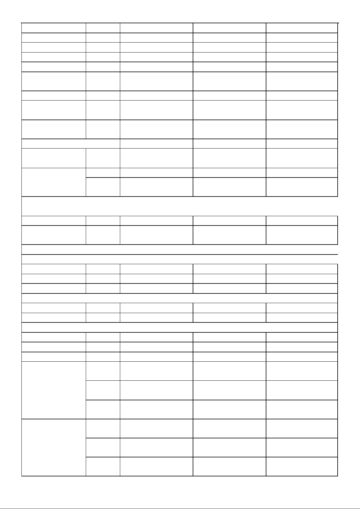
Model No.
+AST-24UW4RDB**00A
+AST-09UW4RVE**00A
+AST-09UW4RVE**00
+AST-12UW4RVE**00A
+AST-12UW4RVE**00
Type
T1, H/P, INVERTER
T1, H/P, INVERTER
T1, H/P, INVERTER
Ratings
Cooling Capacity
W
7000
2600/2600
3500/3500
Heating Capacity
W
7500
2800/2400
4000/3300
Rated Input-Cooling
W
2000
735
1000
Rated Input-Heating
W
2200
680
1025
Moisture Removal
L/h
2.4
0.9
1.2
Air Circulation
High m3/h
1100
550
600
EER for Cooling
W/W
7.9
3.54/6.1
3.5/6.1
COP for Heating
W/W
4.6
4.12/4.0
3.9/4.0
Energy Class
Cooling
A++
A++
A++
Energy Class
Heating
A++
A+
A+
Refrigerant
R32
R32
R32
Refrigerant charge
volume (5M)
g
1700
590
760
Additional ref. Volume
g
30
20
20
Indoor Unit Noise
Level
High(dB (A))
63
56
56
Outdoor Unit Noise
Level
dB (A)
69
63
63
Power Supply
Page 16
16
Voltage, Frequency,
Phase
V
220~240V,50Hz,1P
220-240V~,50Hz,1P
220-240V~,50Hz,1P
Rated Current
Cooling (A)
8.6
3.3
4.4
Heating (A)
9.7
3.1
4.5
System pressures in
cooling rated
conditions
Max suction pressure
MPa
1.6
1.6
1.6
Max discharge
pressure
MPa
4.15
4.15
4.15
System
Compressor
Compressor type
/
Rotary
Rotary
Rotary
Compressor Model
No.
/
GTL232UDPC9AU1LB
KSN98D32UEZ
KSN98D32UEZ
Compressor MFG
/
HIGHLY
GMCC
GMCC
Indoor fan motor
Model No. / K1B310497
DG13G1-16
DG13G1-16
Brand / Broad-ocean
weiling
weiling
outdoor fan motor
Model / DG13Z2D-01
ZWA138D08A
ZWA138D08A
Brand / Broad-ocean
Wolong
Wolong
Connecting Pipe Diameter
Liquid Pipe
inch
3/8
1/4
1/4
Gas Pipe
inch
5/8
3/8
3/8
Cooling Setting
Temperature Range
℃
16~30
16~30
16~30
Heating Setting
Temperature Range
℃
16~30
16~30
16~30
Cooling Operating
Temperature Range
℃
-15~43
-15~43
-15~43
Heating Operating
Temperature Range
℃
-15~24
-15~24
-15~24
Cooling speed
High
(r/min)
1200
1100
1150
Mid(r/min)
1040
940
990
Low
(r/min)
880
800
800
Heating speed
High
(r/min)
1200
1100
1150
Mid(r/min)
1040
940
990
Low
(r/min)
880
800
800
Features
Display on Front
Panel
/
LED
LED
LED
Page 17
17
LCD Wireless
Remote Controller
/
Yes
Yes
Yes
Removable and
washable Panel
/
Yes
Yes
Yes
Washable PP Filter
/
Yes
Yes
Yes
24 Hours Timer / Yes
Yes
Yes
3 Speed and Auto
Indoor Fan Control
/
Yes
Yes
Yes
Vertical Auto Swing
Louver
/
Yes
Yes
Yes
Manual Adjustable
Horizontal Swing
Louver
/
Yes
Yes
Yes
Sleep Operation
/
Yes
Yes
Yes
Smart Function / Yes
Yes
Yes
Super Function / Yes
Yes
Yes
Auto Restart / Yes
Yes
Yes
Dimmer / Yes
Yes
Yes
Other
Net Dimensions
W x H x D (mm)
Indoor Unit
1185X314X231
815×270×210
815×270×210
Outdoor Unit
884X365X793
715×240×486
715 x 240 x 482
Net Weight (Kg)
Indoor Unit
13
8.5
8.5
Outdoor Unit
60
26
27
Packing Dimensions
W x H x D (mm)
Indoor Unit
1236X390X315
870×335×265
870×335×265
Outdoor Unit
1050X500X890
830×315×530
900x335x530
Gross Weight (Kg)
Indoor Unit
15.5
10.5
11
Outdoor Unit
65
29
30
Note:
1、This table just is for reference, when relate parameters is different from actual specification, please use the parameters
of the actual specification which you can get from the product manager.
2、 “**” mean code of Front Panel (relate pictures can check in content 4-1)
3、Net Dimensions(Indoor Unit)depend on the panel you used, the panel is different, the Net Dimensions will be different,
but they are very close, if you need the accurate data, you can consult the product manager.
4、Packing Dimensions (Indoor Unit)depend on the panel you used, the panel is different, the Packing Dimensions will
be different, but they are very close, if you need the accurate data, you can consult the product manager.
5、Gross Weight (Indoor Unit)depend on the panel you used, the panel is different, the Gross Weight will be different,
but they are very close, if you need the accurate data, you can consult the product manager.
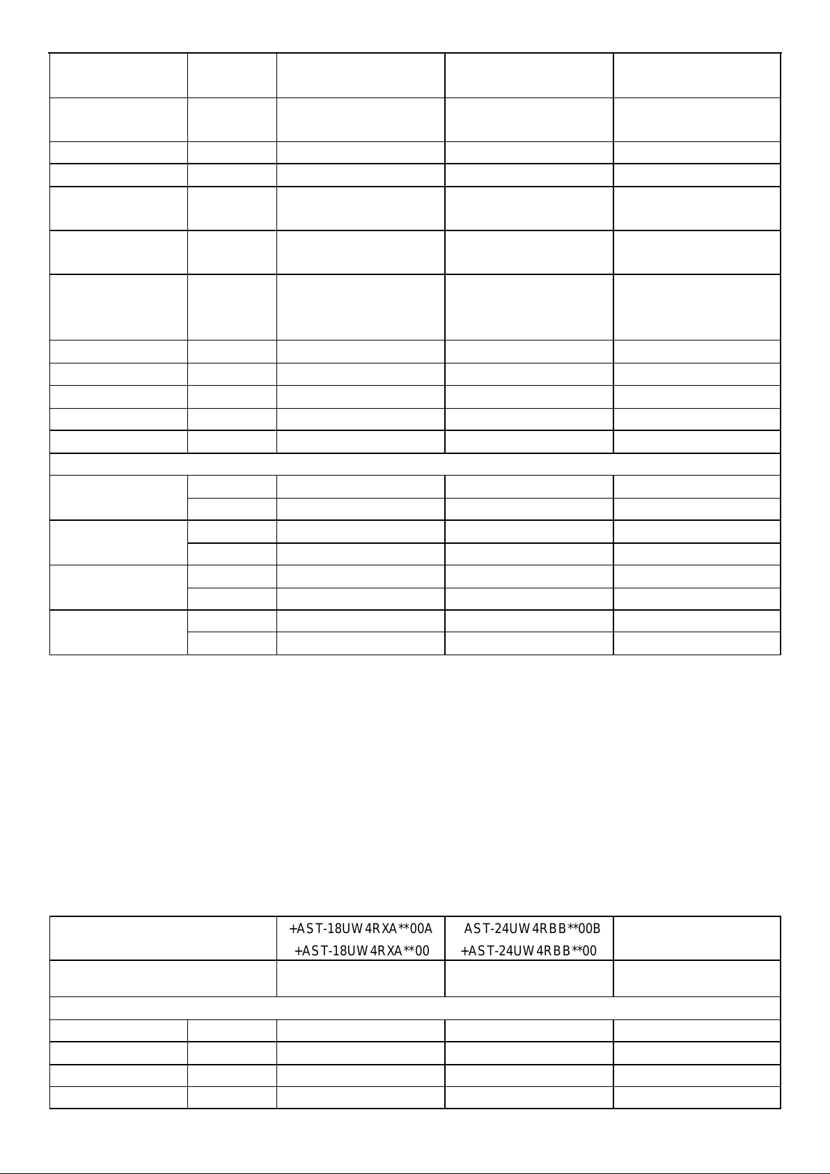
Model No.
+AST-18UW4RXA**00A
+AST-18UW4RXA**00
+AST-24UW4RBB**00B
+AST-24UW4RBB**00
AST-09UW4RYR**01A
Type
T1, H/P, INVERTER
T1, H/P, INVERTER
T1, H/P, INVERTER
Ratings
Cooling Capacity
W
5000/5000
7000/7000
2600
Heating Capacity
W
5600/4700
7100/5300
2700
Rated Input-Cooling
W
1540
2230
855
Rated Input-Heating
W
1550
2240
700
Page 18
18
Moisture Removal
L/h
2
2.5
0.9
Air Circulation
High m3/h
1000
1100
550
EER for Cooling
W/W
3.25/6.10
3.14/6.1
6.1
COP for Heating
W/W
3.61/4.0
3.17/4.0
4.0
Energy Class
Cooling
A++
A++
A++
Energy Class
Heating
A+
A+
A+
Refrigerant
R32
R32
R32
Refrigerant charge
volume (5M)
g
1200
1440
460
Additional ref. Volume
g
20
20
20
Indoor Unit Noise
Level
High(dB (A))
60
63
56
Outdoor Unit Noise
Level
dB (A)
65
64
62
Power Supply
Voltage, Frequency,
Phase
V
220-240V~,50Hz,1P
220-240V~,50Hz,1P
220-240V~,50Hz,1P
Rated Current
Cooling (A)
6.9
9.9
3.9
Heating (A) 7 9.9
3.1
System pressures in
cooling rated
conditions
Max suction pressure
MPa
1.6
1.6
1.6
Max discharge
pressure
MPa
4.15
4.15
4.15
System
Compressor
Compressor type
/
Rotary
Rotary
Rotary
Compressor Model
No.
/
GTD150RDPA8JTA
GTL232UDPC9AU1LB
DS089MJA
Compressor MFG
/
Hatichi
Hitachi
LG
Indoor fan motor
Model No. / DG13G2-07
K1B310497
DG13G1D-03
Brand
/
weiling,Broad-ocean,LT
Broad-ocean
芝浦
outdoor fan motor
Model / K1B310479
DG13Z2D-04
DG13Z1D-02
Brand / Broad-ocean,Olong
Broad-ocean
WOLONG,weiling
Connecting Pipe Diameter
Liquid Pipe
inch
1/4
3/8
1/4
Gas Pipe
inch
1/2
5/8
3/8
Cooling Setting
Temperature Range
℃
16~30
16~30
16~30
Heating Setting
Temperature Range
℃
16~30
16~30
16~30
Cooling Operating
Temperature Range
℃
-15~43
-15~43
-15~43
Page 19
19
Heating Operating
Temperature Range
℃
-15~24
-15~24
-15~24
Cooling speed
High
(r/min)
1200
1200
1200
Mid(r/min)
1040
1040
1000
Low
(r/min)
880
880
800
Heating speed
High
(r/min)
1200
1200
1200
Mid(r/min)
1040
1040
1000
Low
(r/min)
880
880
800
Features
Display on Front
Panel
/
LED
LED
LED
LCD Wireless
Remote Controller
/
Yes
Yes
Yes
Removable and
washable Panel
/
Yes
Yes
Yes
Washable PP Filter
/
Yes
Yes
Yes
24 Hours Timer / Yes
Yes
Yes
3 Speed and Auto
Indoor Fan Control
/
Yes
Yes
Yes
Vertical Auto Swing
Louver
/
Yes
Yes
Yes
Manual Adjustable
Horizontal Swing
Louver
/
Yes
Yes
Yes
Sleep Operation
/
Yes
Yes
Yes
Smart Function / Yes
Yes
Yes
Super Function / Yes
Yes
Yes
Auto Restart / Yes
Yes
Yes
Dimmer / Yes
Yes
Yes
Other
Net Dimensions
W x H x D (mm)
Indoor Unit
915X315X229
1087X315X229
790X255X200
Outdoor Unit
810X280X585
860X 310X667
660×240×483
Net Weight (Kg)
Indoor Unit
12
13
7.1
Outdoor Unit
38
48
22
Packing Dimensions
W x H x D (mm)
Indoor Unit
1000×390×315
1170X390X315
850X320X260
Outdoor Unit
940×385×630
995 X420X720
780×315×530
Gross Weight (Kg)
Indoor Unit
14
15.5
8.6
Outdoor Unit
42
52
25
Note:
1、This table just is for reference, when relate parameters is different from actual specification, please use the parameters
of the actual specification which you can get from the product manager.
2、 “**” mean code of Front Panel (relate pictures can check in content 4-1)
3、Net Dimensions(Indoor Unit)depend on the panel you used, the panel is different, the Net Dimensions will be different,
Page 20
20
but they are very close, if you need the accurate data, you can consult the product manager.
4、Packing Dimensions (Indoor Unit)depend on the panel you used, the panel is different, the Packing Dimensions will
be different, but they are very close, if you need the accurate data, you can consult the product manager.
5、Gross Weight (Indoor Unit)depend on the panel you used, the panel is different, the Gross Weight will be different,
but they are very close, if you need the accurate data, you can consult the product manager.
Model No.
AS-12UW4RYR**01A
AST-18UW4RXS**01
AST-24UW4RBT**01
Type
T1, H/P, INVERTER
T1, H/P, INVERTER
T1, H/P, INVERTER
Ratings
Cooling Capacity
W
3400
5000
6500
Heating Capacity
W
3800
5600
7100
Rated Input-Cooling
W
1140
1540
2060
Rated Input-Heating
W
1050
1550
2150
Moisture Removal
L/h
1.2
1.75
1.6
Air Circulation
High m3/h
550
950
1100
EER for Cooling
W/W
6.10
6.1
COP for Heating
W/W
4.0
4
Energy Class
Cooling
A++
A
A++
Energy Class
Heating
A+
A
A+
Refrigerant
R32
R32
R32
Refrigerant charge
volume (5M)
g
620
1150
1300
Additional ref. Volume
g
20
20
30
Indoor Unit Noise
Level
High(dB (A))
56
59
63
Outdoor Unit Noise
Level
dB (A)
62
65
64
Power Supply
Voltage, Frequency,
Phase
V
220-240V~,50Hz,1P
220-240V~,50Hz,1P
220-240V~,50Hz,1P
Rated Current
Cooling (A)
5.0
6.9
9.2
Heating (A)
4.7
7
9.6
System pressures in cooling rated conditions
Max suction pressure
MPa
1.6
1.6
1.6
Max discharge
pressure
MPa
4.15
4.15
4.15
System
Compressor
Compressor type
/
Rotary
Rotary
Rotary
Compressor Model
No.
/
KSK89D59UEZC
KTN150D42UFZB
GTD186UKQA8JT6
Compressor MFG
/
GMCC
GMCC
Hitachi
Indoor fan motor
Model No. / DG13G1D-03
DG13G2-10
DG13G3D-04
Page 21
21
Brand
/
芝浦
Broad-
ocean,Welling,LT,Tongde
Welling,Broad-
ocean,Wolong
outdoor fan motor
Model / DG13Z1D-02
K1B310479
ZW511A800002
Brand / WOLONG,weiling
Broad-ocean,Olong
Welling,Broad-
ocean,Wolong
Connecting Pipe Diameter
Liquid Pipe
inch
1/4
1/4
3/8
Gas Pipe
inch
3/8
1/2
5/8
Cooling Setting
Temperature Range
℃
16-30
16-30
16-30
Heating Setting
Temperature Range
℃
16-30
16-30
16-30
Cooling Operating
Temperature Range
℃
-15~43
-15~43
-15~43
Heating Operating
Temperature Range
℃
-15-24
-15-24
-15-24
Cooling speed
High
(r/min)
1250
1200
1200
Mid(r/min)
1000
1000
1000
Low
(r/min)
850
870
850
Heating speed
High
(r/min)
1250
1200
1200
Mid(r/min)
1000
1000
1000
Low
(r/min)
850
870
850
Features
Display on Front
Panel
/
LED
LED
LED
LCD Wireless
Remote Controller
/
Yes
Yes
Yes
Removable and
washable Panel
/
Yes
Yes
Yes
Washable PP Filter
/
Yes
Yes
Yes
24 Hours Timer / Yes
Yes
Yes
3 Speed and Auto
Indoor Fan Control
/
Yes
Yes
Yes
Vertical Auto Swing
Louver
/
Yes
Yes
Yes
Manual Adjustable
Horizontal Swing
Louver
/
Yes
Yes
Yes
Sleep Operation
/
Yes
Yes
Yes
Smart Function / Yes
Yes
Yes
Super Function / Yes
Yes
Yes
Auto Restart / Yes
Yes
Yes
Page 22
22
Dimmer / Yes
Yes
Yes
Other
Net Dimensions
W x H x D (mm)
Indoor Unit
790X255X200
890*300*220
998×325×225
Outdoor Unit
660X483X240
810*280*585
860×310×667
Net Weight (Kg)
Indoor Unit
7.1
10
11
Outdoor Unit
23
34
42
Packing Dimensions
W x H x D (mm)
Indoor Unit
850×320×260
960*365*300
1060×390×315
Outdoor Unit
780×530×315
935*385*630
995×420×720
Gross Weight (Kg)
Indoor Unit
8.6
12
13.5
Outdoor Unit
26
38.5
46
Note:
1、This table just is for reference, when relate parameters is different from actual specification, please use the parameters
of the actual specification which you can get from the product manager.
2、 “**” mean code of Front Panel (relate pictures can check in content 4-1)
3、Net Dimensions(Indoor Unit)depend on the panel you used, the panel is different, the Net Dimensions will be different,
but they are very close, if you need the accurate data, you can consult the product manager.
4、Packing Dimensions (Indoor Unit)depend on the panel you used, the panel is different, the Packing Dimensions will
be different, but they are very close, if you need the accurate data, you can consult the product manager.
5、Gross Weight (Indoor Unit)depend on the panel you used, the panel is different, the Gross Weight will be different,
but they are very close, if you need the accurate data, you can consult the product manager.
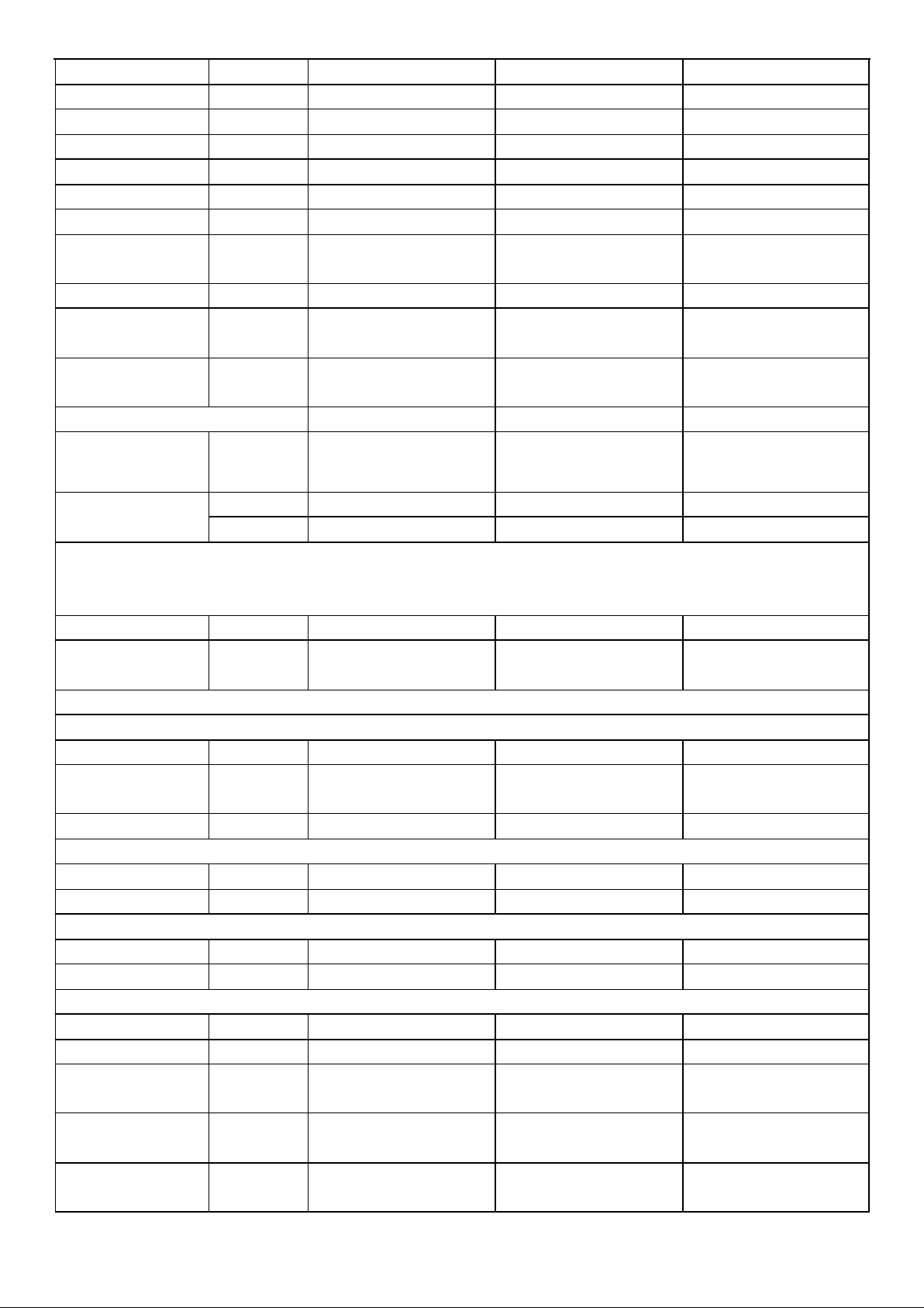
Model No.
AS-09UW4RYR**01A
+AST-09UW4RXU**00
+AST-12UW4RXU**00
Type
T1, H/P, INVERTER
T1, H/P, INVERTER
T1, H/P, INVERTER
Ratings
Cooling Capacity
W
2600
2600
3500
Heating Capacity
W
2700
3200
4200
Rated Input-Cooling
W
855
540
790
Rated Input-Heating
W
700
720
980
Moisture Removal
L/h
0.9
0.9
1.2
Air Circulation
High m3/h
550
600
650
EER for Cooling
W/W
6.1
9.10
4.43
COP for Heating
W/W
4.0
5.10
4.28
Energy Class
Cooling
A++
A+++
A++
Energy Class
Heating
A+
A+++
A++
Refrigerant
R32
R32
R32
Refrigerant charge
volume (5M)
g
460
860
860
Additional ref. Volume
g
20
20
20
Indoor Unit Noise
Level
High(dB (A))
56
55
56
Outdoor Unit Noise
Level
dB (A)
62
59
61
Power Supply
Voltage, Frequency,
Phase
V
230V,50Hz,1P
220~240V,50Hz,1P
220-240V~,50Hz,1P
Rated Current
Cooling (A)
3.9
2.5
3.5
Page 23
23
Heating (A)
3.1
3.2
4.3
System pressures in
cooling rated
conditions
Max suction pressure
MPa
1.6
1.6
1.6
Max discharge
pressure
MPa
4.15
4.15
4.15
System
Compressor
Compressor type
/
Rotary
Rotary
Rotary
Compressor Model
No.
/
DS089MJA
KSN98D58UFZA
KSN98D58UFZ
Compressor MFG
/
LG
GMCC
GMCC
Indoor fan motor
Model No. / DG13G1D-03
ZWA108D02B
ZWA108D02B
Brand
/
芝浦
WOLONG
WOLONG
outdoor fan motor
Model / DG13Z1D-02
ZWA228D44B
ZWA228D44B
Brand / WOLONG,weiling
WOLONG
WOLONG
Connecting Pipe Diameter
Liquid Pipe
inch
1/4
1/4
1/4
Gas Pipe
inch
3/8
3/8
3/8
Cooling Setting
Temperature Range
℃
16-30
16-30
16-30
Heating Setting
Temperature Range
℃
16-30
16-30
16-30
Cooling Operating
Temperature Range
℃
-15~43
-15~43
-15~43
Heating Operating
Temperature Range
℃
-15-24
-20-24
-20-24
Cooling speed
High
(r/min)
1200
1100
1200
Mid(r/min)
1000
940
1000
Low
(r/min)
800
800
870
Heating speed
High
(r/min)
1200
1100
1200
Mid(r/min)
1000
940
1000
Low
(r/min)
800
800
870
Features
Display on Front
Panel
/
LED
LED
LED
Page 24
24
LCD Wireless
Remote Controller
/
Yes
Yes
Yes
Removable and
washable Panel
/
Yes
Yes
Yes
Washable PP Filter
/
Yes
Yes
Yes
24 Hours Timer / Yes
Yes
Yes
3 Speed and Auto
Indoor Fan Control
/
Yes
Yes
Yes
Vertical Auto Swing
Louver
/
Yes
Yes
Yes
Manual Adjustable
Horizontal Swing
Louver
/
Yes
Yes
Yes
Sleep Operation
/
Yes
Yes
Yes
Smart Function / Yes
Yes
Yes
Super Function / Yes
Yes
Yes
Auto Restart / Yes
Yes
Yes
Dimmer / Yes
Yes
Yes
Other
Net Dimensions
W x H x D (mm)
Indoor Unit
790×255×200
850×270×208
950×295×298
Outdoor Unit
660×483×240
810×280×585
810×585×280
Net Weight (Kg)
Indoor Unit
7.1
12
13
Outdoor Unit
23
36
37
Packing Dimensions
W x H x D (mm)
Indoor Unit
850×320×260
900×260×335
1060×400×400
Outdoor Unit
780×530×315
940×385×630
940×630×385
Gross Weight (Kg)
Indoor Unit
8.6
14
17.5
Outdoor Unit
26
40
41
Note:
1、This table just is for reference, when relate parameters is different from actual specification, please use the parameters
of the actual specification which you can get from the product manager.
2、 “**” mean code of Front Panel (relate pictures can check in content 4-1)
3、Net Dimensions(Indoor Unit)depend on the panel you used, the panel is different, the Net Dimensions will be different,
but they are very close, if you need the accurate data, you can consult the product manager.
4、Packing Dimensions (Indoor Unit)depend on the panel you used, the panel is different, the Packing Dimensions will
be different, but they are very close, if you need the accurate data, you can consult the product manager.
5、Gross Weight (Indoor Unit)depend on the panel you used, the panel is different, the Gross Weight will be different,
but they are very close, if you need the accurate data, you can consult the product manager.
Model No.
+AST-09UW4RXV**00
+AST-12UW4RXV**00
Type
T1, H/P, INVERTER
T1, H/P, INVERTER
Ratings
Cooling Capacity
W
2600
3500
Heating Capacity
W
3200
4200
Rated Input-Cooling
W
540
790
Rated Input-Heating
W
720
980
Moisture Removal
L/h
0.9
1.2
Air Circulation
High m3/h
600
650
Page 25
25
EER for Cooling
W/W
9.10
4.43
COP for Heating
W/W
5.10
4.28
Energy Class
Cooling
A+++
A+++
Energy Class
Heating
A+++
A+++
Refrigerant
R32
R32
Refrigerant charge
volume (5M)
g
860
860
Additional ref. Volume
g
20
20
Indoor Unit Noise Level
High(dB
(A))
56
55
Outdoor Unit Noise
Level
dB (A)
59
61
Power Supply
Voltage, Frequency,
Phase
V
220~240V,50Hz,1P
220-240V~,50Hz,1P
Rated Current
Cooling (A)
2.5
3.5
Heating
(A)
3.2
4.3
System pressures in
cooling rated conditions
Max suction pressure
MPa
1.6
1.6
Max discharge
pressure
MPa
4.15
4.15
System
Compressor
Compressor type
/
Rotary
Rotary
Compressor Model No.
/
KSN98D58UFZA
KSN98D58UFZ
Compressor MFG
/
GMCC
GMCC
Indoor fan motor
Model No.
/
ZWA108D02B
ZWA108D02B
Brand
/
WOLONG
WOLONG
outdoor fan motor
Model
/
ZWA108D02B
ZWA108D02B
Brand
/
WOLONG
WOLONG
Indoor fan motor
Cooling speed
High
(r/min)
1100
1200
Mid
(r/min)
940
1000
Low
(r/min)
800
870
Heating speed
High
(r/min)
1100
1200
Mid
(r/min)
940
1000
Low
(r/min)
800
870
Page 26
26
Connecting Pipe
Diameter
Liquid Pipe
inch
1/4
1/4
Gas Pipe
inch
3/8
3/8
Cooling Setting
Temperature Range
℃
16-30
16-30
Heating Setting
Temperature Range
℃
16-30
16-30
Cooling Operating
Temperature Range
℃
-15~43
-15~43
Heating Operating
Temperature Range
℃
-20-24
-20-24
Features
Display on Front Panel
/
LED
LED
LCD Wireless Remote
Controller
/
Yes
Yes
Removable and
washable Panel
/
Yes
Yes
Washable PP Filter
/
Yes
Yes
24 Hours Timer / Yes
Yes
3 Speed and Auto
Indoor Fan Control
/
Yes
Yes
Vertical Auto Swing
Louver
/
Yes
Yes
Manual Adjustable
Horizontal Swing
Louver
/
Yes
Yes
Sleep Operation
/
Yes
Yes
Smart Function / Yes
Yes
Super Function / Yes
Yes
Auto Restart / Yes
Yes
Dimmer / Yes
Yes
Other
Net Dimensions W
x H x D (mm)
Indoor Unit
850×270×208
950×295×298
Outdoor
Unit
810×280×585
810×585×280
Net Weight (Kg)
Indoor Unit
12
13
Outdoor
Unit
36
36
Packing Dimensions
W x H x D (mm)
Indoor Unit
900×260×335
1060×400×400
Outdoor
Unit
940×385×630
940×630×385
Gross Weight (Kg)
Indoor Unit
14
17.5
Outdoor
Unit
40
40
Note:
1、This table just is for reference, when relate parameters is different from actual specification, please use the parameters
Page 27
27
of the actual specification which you can get from the product manager.
2、 “**” mean code of Front Panel (relate pictures can check in content 4-1)
3、Net Dimensions(Indoor Unit)depend on the panel you used, the panel is different, the Net Dimensions will be different,
but they are very close, if you need the accurate data, you can consult the product manager.
4、Packing Dimensions (Indoor Unit)depend on the panel you used, the panel is different, the Packing Dimensions will
be different, but they are very close, if you need the accurate data, you can consult the product manager.
5、Gross Weight (Indoor Unit)depend on the panel you used, the panel is different, the Gross Weight will be different,
but they are very close, if you need the accurate data, you can consult the product manager.
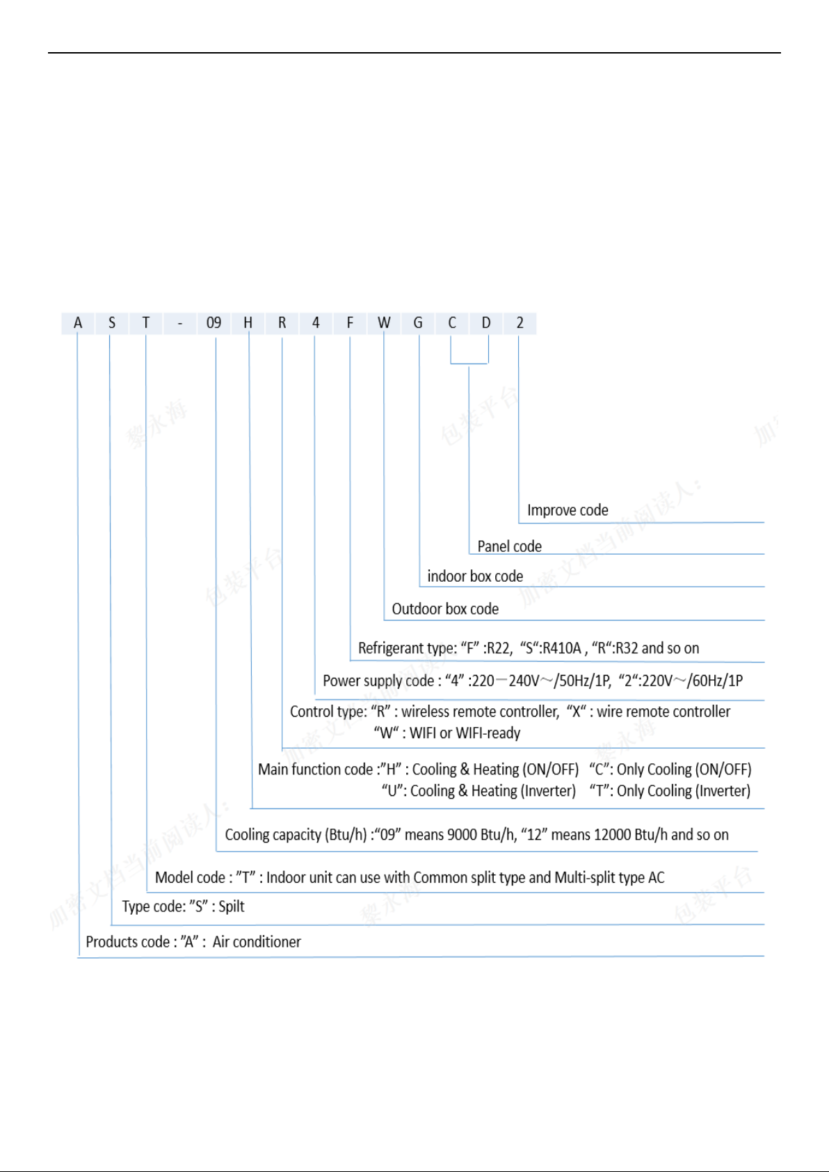
3. Name of Split type conditioner introduce
Page 28
28
4. Pro duct Picture and Drawing
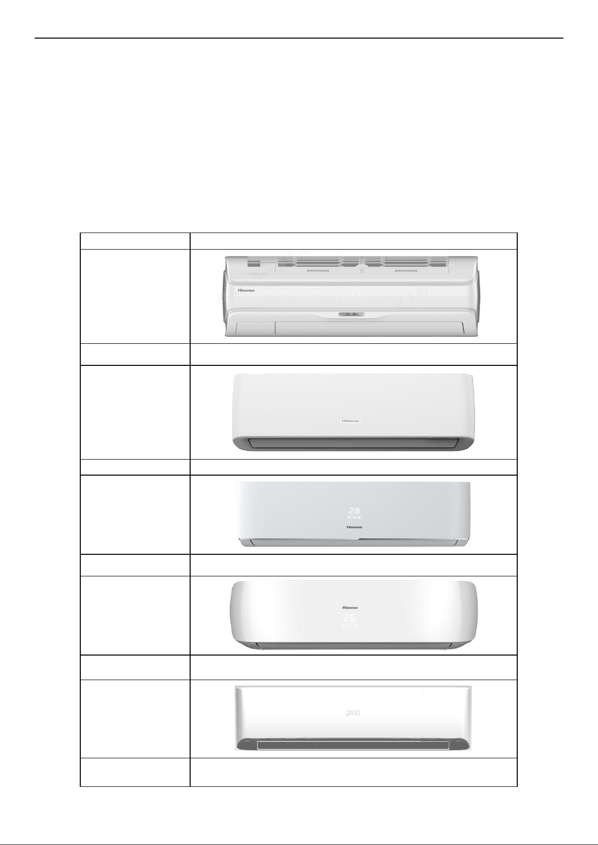
4-1. Product Pictures
Indoor units:
Front Panel
QD
View
Front Panel
QE
View
Front Panel
DJ
View
Front Panel
TG
View
Front Panel
TQ
View
Front Panel
CA
Page 29
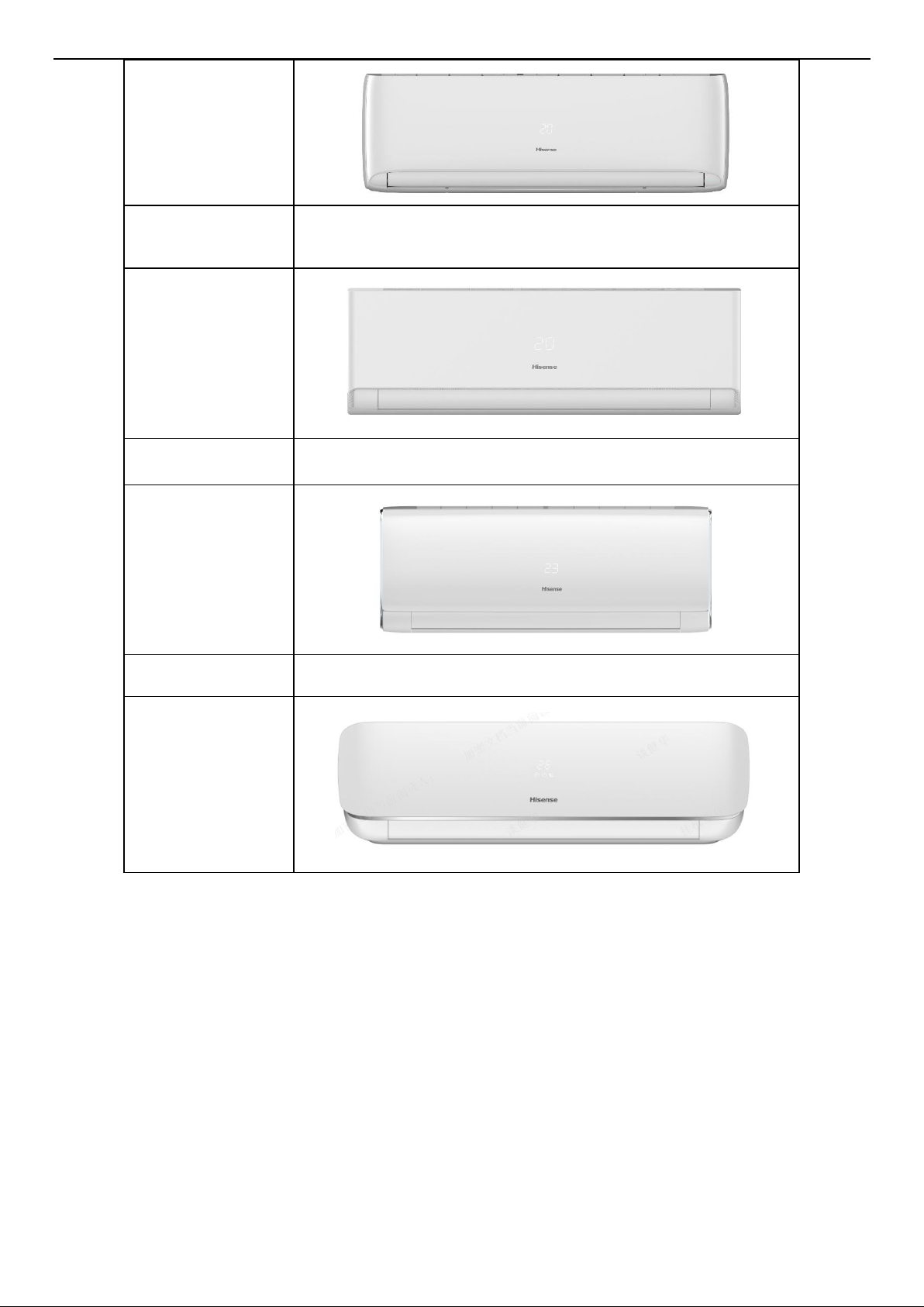
29
View
Front Panel
KA
View
Front Panel
KB
View
Front Panel
KG
View
Page 30
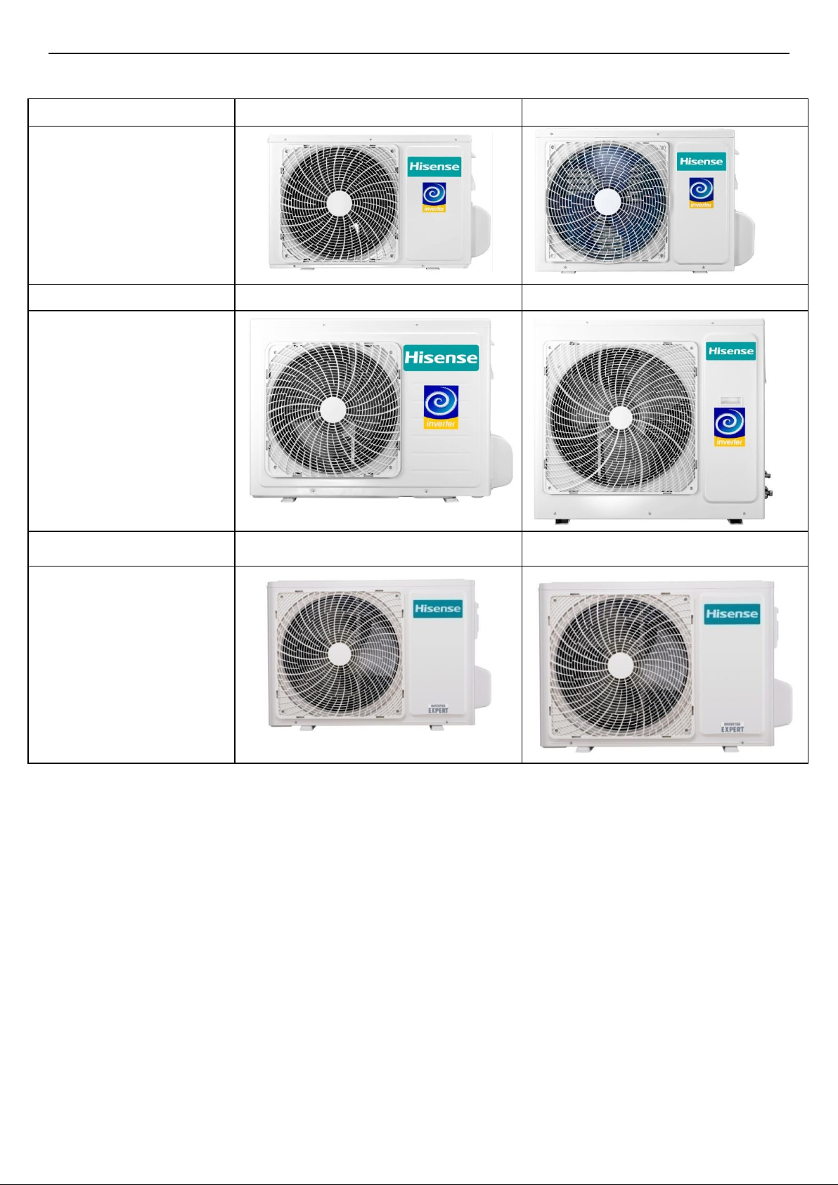
30
Outdoor Units:
Capacity (Btu)
V(W1M)
Y(W1R)
View
Capacity (Btu)
F(W2M)
D(W5F)
View
Capacity (Btu)
X(W1T)
B(W2T)
View
Page 31

31
Remote controller:
Model
L1-04
R1-03
R2-01
View
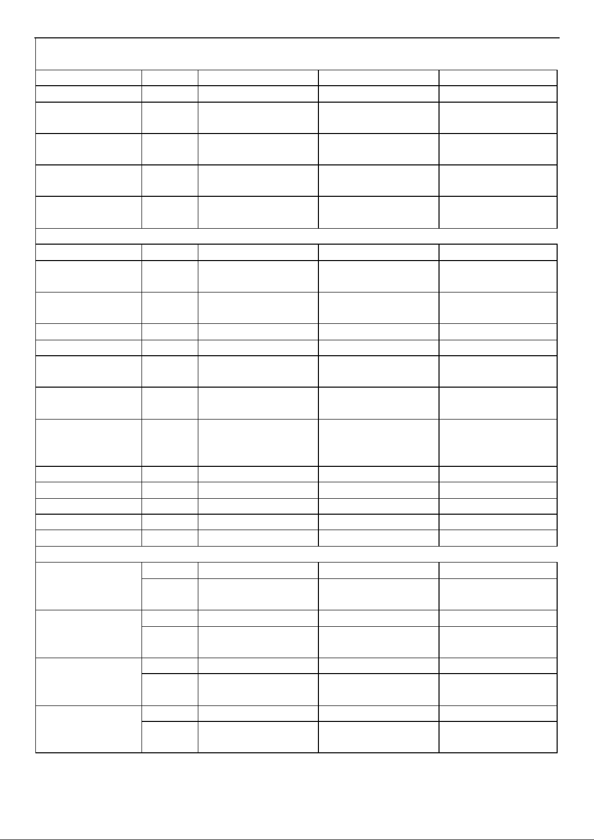
4-2. Product dimensions
Indoor units:
Page 32

32
Model
W (mm)
H (mm)
D (mm)
+AST-09UW4RXETQ00B
906
270
210
+AST-12UW4RXETQ00B
906
270
210
+AST-18UW4RBATQ00A
1014
315
231
+AST-24UW4RDBTQ00A
1185
315
231
+AST-09UW4RVEDJ00A
815
270
210
+AST-12UW4RVEDJ00A
815
270
210
+AST-18UW4RXADJ00A
915
315
229
+AST-24UW4RBBDJ00B
1087
315
229
+AST-09UW4RVETG00
950
272
207
+AST-12UW4RVETG00
950
272
207
+AST-18UW4RXATG00
1050
320
235
+AST-24UW4RBBTG00
1219
320
235
AS-09UW4RYRCA01A
790
255
200
AS-12UW4RYRCA01A
790
255
200
AST-18UW4RXSCA01
890
300
220
AST-24UW4RBTCA01
998
325
225
+AST-09UW4RXUQD00
950
295
298
+AST-12UW4RXUQD00
950
295
298
+AST-09UW4RXVQE00
883
304
199
+AST-12UW4RXVQE00
883
304
199
AS-09UW4RYRKA01A
798
256
191
AS-12UW4RYRKA01A
798
256
191
AST-18UW4RXSKA01
896
300
214
AST-24UW4RBTKA01
1008
325
217
AS-09UW4RYRKB01A
833
256
203
AS-12UW4RYRKB01A
833
256
203
AST-18UW4RXSKB01
943
300
245
AST-24UW4RBTKB01
1038
325
237
Page 33

33
Outdoor units:
Model
L1
(mm)
L2
(mm)
L3
(mm)
L4
(mm)
L5
(mm)
L6
(mm)
L7
(mm)
+AST-09UW4RXE**00B
510
310
886
810
280
585
338
+AST-12UW4RXE**00B
510
310
886
810
280
585
338
+AST-18UW4RBA**00A
542
341
935
860
310
667
368
+AST-24UW4RDB**00A
662
390
959
884
365.5
793
414
+AST-09UW4RVE**00A
443
264
776
715
240
486
290
+AST-12UW4RVE**00A
443
264
776
715
240
486
290
+AST-18UW4RXA**00A
510
310
886
810
280
585
338
+AST-24UW4RBB**00B
542
341
935
860
310
667
368
+AST-09UW4RVE**00
443
264
776
715
240
486
290
+AST-12UW4RVE**00
443
264
776
715
240
486
290
Page 34

34
+AST-18UW4RXA**00
510
310
886
810
280
585
338
+AST-24UW4RBB**00
542
341
935
860
310
667
368
AS-09UW4RYR**01A
443
264
776
715
240
486
290
AS-12UW4RYR**01A
443
264
776
715
240
486
290
AST-18UW4RXS**01
510
310
886
810
280
585
338
AST-24UW4RBT**01
542
341
935
860
310
667
368
+AST-09UW4RXU**00
510
310
886
810
280
585
338
+AST-12UW4RXU**00
510
310
886
810
280
585
338
+AST-09UW4RXV**00
510
310
886
810
280
585
338
+AST-12UW4RXV**00
510
310
886
810
280
585
338
Note: “ ** ” mean code of Front Panel.
Page 35

35
5. Installation Instruction
To prevent abnorm al heat generation and the possibility of fire, do not place
obstacles, enclosures and grilles in front of or surrounding the air conditioner in
a way that may clock air flow. And, m ore than 1 m eter away from any antenna
or power lines or connecting wires used for TV, radio, telephone, security
system, or intercom. Electrical noise from any of these sources may affect operation.
5-1. Main Tools for Installation and Maintenance
Just for reference, some tools may be different from each pl ace, you can use the s i milar tools to i ns tall the products.
Page 36

36
5-2. Installation Flow Diagram
Note: this flow is only for reference, the more details please find the manual of Use and installation instructions
Page 37

37
5-3. Installation Place and Condition
Indoor unit
Avoid:
△ direct sunlight.
△ nearby heat sources that may affect performance of the unit.
△ areas where leakage of flammable gas may be expected.
△ places where large amounts of oil mist exist.
Do:
△ Select an appropriate position from which every corner of the room can be uniformly cooled.
△ Select a location that will hold the weight of the unit.
△ Select a location where tubing and drain hose have the shortest run to the outside. (See a)
△ Allow room for operation and maintenance as well as unrestricted air flow around the unit. (See
b)
△ Install the unit within the maximum elevation difference (H) above or below the outdoor unit
and within a total tubing length (L) from the outdoor unit as detailed (See table 1 and c)
a
b
c
table 1
Capacity
(Btu/h)
Pipe Size
Standard
Length
(m)
Max.
Elevation
B (m)
Max.
Length
A (m)
Min.
Length
A (m)
Suggest
Additional
Refrigerant
(g/m)
GAS
LIQUID
9k
3/8"(Ø9.52)
1/4"(Ø6.35)
5 5 15 3 20
1/2"(Ø12.7)
1/4"(Ø6.35)
5 5 15 3 20
12k
3/8"(Ø9.52)
1/4"(Ø6.35)
5 5 15 3 20
1/2"(Ø12.7)
1/4"(Ø6.35)
5 5 15 3 20
18k
1/2"(Ø12.7)
1/4"(Ø6.35)
5 5 15 3 20
5/8"(Ø15.88)
1/4"(Ø6.35)
5 5 15 3 20
5/8"(Ø15.88)
3/8"(Ø9.52)
5 5 15 3 30
24k
1/2"(Ø12.7)
1/4"(Ø6.35)
5 5 15 3 20
5/8"(Ø15.88)
1/4"(Ø6.35)
5 5 15 3 20
5/8"(Ø15.88)
3/8"(Ø9.52)
5 5 15 3 30
* If total tubing length becomes 7.5 to 15 m (max.), charge additional refrigerant as the table1
for reference. And no additional compressor oil is necessary.
* Min length just is for reference, if too short maybe lead to some abnormal noise.
Page 38

38
Outdoor unit
Avoid:
△ Heat sources, exhaust fans, etc.
△ Damp, humid or uneven locations.
DO:
△ Choose a place as cool as possible.
△ Choose a place that is well ventilated.
△ Allow enough room around the unit for air intake or exhaust and possible maintenance. (see a1,
b1 & c1)
△ Provide a solid base (level concrete pad, concrete block, 10 × 40 cm beams or equal), a
minimum of 10 cm above ground level to reduce humidity and protect the unit against possible
water damage
and decreased service life.
△ If the installation bag has rubber pads, it is strongly recommended for use to reduce vibration
and noise.
△ Use lug bolts or equal to bolt down unit, reducing vibration and noise.
a1
b1
c1
Page 39

39
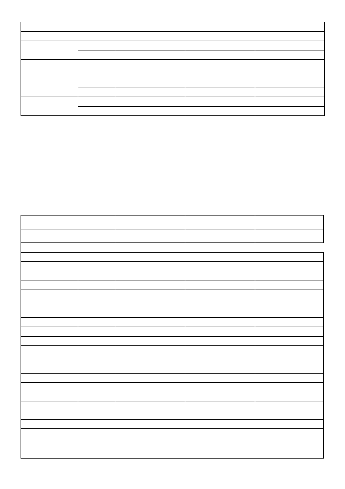
Recommended Wire Diameter:
Capacity size
Wire Diameter(mm2)
Fuse or Circuit Breaker Capacity
5K~12k
1.0(Power wire)/1.0(Connect wire)
3.15A or 5A(indoor)/15A
(outdoor)
18k
2.5(Power wire)/1.5(Connect wire)
3.15A or 5A(indoor)/20A
(outdoor)
22K~30K
2.5(Power wire)/2.5(Connect wire)
3.15A or 5A(indoor)/30A
(outdoor)
Page 40

40
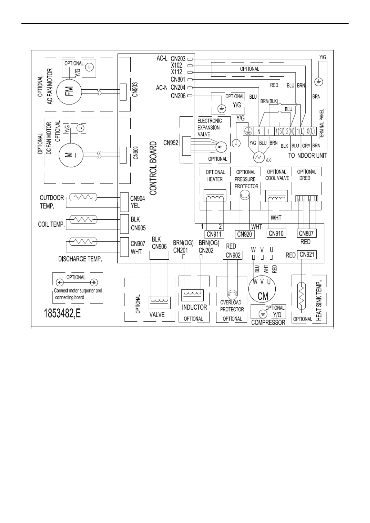
5-4. Electric Wiring Diagram
Model
Indoor Unit DIAGRAM
Outdoor Unit DIAGRAM
+AST-09UW4RXE**00B
1897944
1853482
+AST-12UW4RXE**00B
1897944
1853482
+AST-18UW4RBA**00A
1897944
1853482
+AST-24UW4RDB**00A
1897944
1853482
+AST-09UW4RVE**00A
1897944
1853482
+AST-12UW4RVE**00A
1897944
1853482
+AST-18UW4RXA**00A
1897944
1853482
+AST-24UW4RBB**00B
1897944
1853482
+AST-09UW4RVE**00
1565467
1853482
+AST-12UW4RVE**00
1565467
1853482
+AST-18UW4RXA**00
1812496
1853482
+AST-24UW4RBB**00
1897944
1853482
AS-09UW4RYR**01A
1897944
1853482
AS-12UW4RYR**01A
1897944
1853482
AST-18UW4RXS**01
1897944
1853482
AST-24UW4RBT**01
1897944
1853482
+AST-09UW4RXU**00
2080141
1853482
+AST-12UW4RXU**00
2080141
1853482
+AST-09UW4RXV**00
1897944
1853482
+AST-12UW4RXV**00
1897944
1853482
Note: “ ** ” mean code of Front Panel.
Page 41

41
Indoor Unit DIAGRAM:
1897944
1565467
Page 42
42
Outdoor Model:
1853482
Page 43

43
5-5. Refrigerant Flow System
NOTE: In different models, the throttle assembly may be Capillary or Electronic expansion valve.
Page 44

44
5-6. Air Purging and Leakage Test
1. Connect charging hose of manifold valve to charge end of low pressure valve (both high/low
pressure valves must be tightly shut).
2. Connect joint of charging hose to vacuum pump.
3. Fully open the handle of Lo manifold valve.
4. Open the vacuum pump to evacuate. At the beginning, slightly loosen joint nut of low pressure
valve to check if there is air coming inside. (If noise of vacuum pump has been changed, the
reading of multimeter is 0) Then tighten the nut.
5. Keep evacuating for more than 15mins and make sure the reading of multi-meter is -1.0 X10⁵
pa (-76cmHg).
6. Check the vacuum with the gage manifold valve, then close the gage manifold valve, and stop
the vacuum pump.
7. Leave it for one or two minutes. Make sure the pointer of the gage manifold valve remains in
the same position.
8. Remove the gage manifold valve quickly from the service port of the stop valve.
After refrigerant pipes are connected and evacuated, fully open all stop valves on gas and liquid
pipe sides.
9. Opening without fully opening lowers the performance and cause dangerous.
10. Tighten the cap to the service port to obtain the initial status.
11. Retighten the cap
12. Leak test
Page 45

45
5-7. Test Running
△ Check after Installation
Items to be checked
Possible malfunction
Has it been fixed firmly?
The unit may drop, shake or emit noise.
Have you done the refrigerant leakage test?
It may cause insufficient
cooling(heating)capacity
Is heat insulation sufficient?
It may cause condensation and dripping.
Is water drainage satisfactory?
It may cause condensation and dripping.
Is the voltage in accordance with the rated
voltage marked on the nameplate?
It may cause electric malfunction or damage
the product.
Is the electric wiring and piping connection
installed correctly and securely?
It may cause electric malfunction or damage
the part.
Has the unit been connected to a secure
earth connection?
It may cause electrical leakage.
Is the power cord specified?
It may cause electric malfunction or damage
the part.
Are the inlet and outlet openings blocked?
It may cause insufficient
cooling(heating)capacity.
Is the length of connection pipes and
refrigerant capacity been recorded?
The refrigerant capacity is not accurate.
△Operation Test
1. Before Operation Test
(1)Do not switch on power before installation is finished completely.
(2)Electric wiring must be connected correctly and securely.
(3)Cut-off valves of the connection pipes should be opened.
(4)All the impurities such as scraps and thrums must be cleared from the unit.
2. Operation Test Method
(1)Switch on power and press “ON/OFF” button on the remote controller to start the operation.
(2)Press MODE button to select the COOL, HEAT (Cooling only unit is not available), FAN to check
whether the operation is normal or not.
Page 46

46
6. Function Operation
6-1. Operation Range (cooling and heating)
Temperature
Cooling operation
Heating operation
Indoor
temperature
Max
32℃
27℃
Min
21℃
7℃
outdoor
temperature
Max
43℃
24℃
Min
*note
-15℃
*Optimum performance will be achieved within these operating temperature. If air conditioner is used
outside of the above conditions, the protective device may trip and stop the appliance.
*For Tropical (T3) Climate condition models, the outdoor max temperature is 55 ℃ instead of 43 ℃
*For some models, can keep cooling at -15 ℃ outdoor ambient via unique design. Normally,
optimum cooling performance will be achieved above 21 ℃. Please consult the merchant to get
more information.
*For some models, can keep heating at -15 ℃ outdoor ambient , some models heat at -20 ℃
outdoor ambient,even heat at lower outdoor ambient
The temperature of some products is allowed beyond the range. In specific situation, please consult
the merchant. When relative humidity is above 80%, if the air conditioner runs in COOLING or DRY
mode with door or window opened for a long time, dew may drip down from the outlet.
Page 47

47
6-2. Remote Controller Operation & Function
△Remote Controller Instruction
L1-04
Page 48

48
R2-01
Page 49

49
R1-03
Page 50

50
△Function Instruction
1.Major general technical parameters
1-1 Remote receiver distance(front of the air conditioner): 8 m.
1-2 Remote receiver angle: Less than 60 degrees.
1-3 Temperature control accuracy: ±1℃.
1-4 Time error: Less than 1%.
2. Functions of the controller
2-1 Display panel
I. Control functions of the remote controller (See operating and installation manual)
II. Display of the indoor unit
Information on the screen:
Displaying Scheme:
7-segment tube:Display set temperature or indoor temperature , and display fault code in trouble
indicating. An error code is displayed according to the signal from the indoor CPU. The error code
will flash for 5 seconds while displayed.
Running LED:It is on during operation. It is flashing when the unit defrost.
TIMER LED:When the timer mode works, the LED will be lighted.
Sleep LED:When the sleep mode works, the LED will be lighted, and after 10s, the LED will be off.
Compressor LED:It lights up when compressor is running.
Remote control receiver: This section receives signals from the remote control.
3. Control function
3-1 Emergency switch
If the appliance under the Stand-by state, all the Operation Mode, Air volume, Temperature
Setting , Forced Cooling function will be restored as the last time setting when you press on the
“ON/OFF” button, but lost the Air flow direction setting.
If the appliance was connected to the power at first time, it would operate in the auto mode, It
will keep in stand-by state if you press the “ON/OFF” button during the normal operation.
When the appliance under the Stand-by state, press and hold the emergency switch for 5
seconds, the buzzer rings for 1 times, and it will operate in cooling mode, and the indoor fan speed
is set to high-speed, it running has nothing to do with the room temperature.
When press the emergency switch or receive the signal of the remote control, it will exit this
mode, and it will operate with the corresponding order.
3-2 Operator-machine communication
If the unit has I feel function, when the I feel function is set by the remote control, the room
temperature will depend on the remote control and it will be detected by the sensor of the remote
control. Normally the remote control will automatically transmits a signal at an interval of 10
minutes(only for H1 remote control, it is 9 minutes), but if the room temperature changed exceed
1℃ in a short period of time, the remote control will transmits a signal within 2 minutes. If the
indoor unit has not received a remote signal within 30 minutes, the ro om temperature will depend
on the room temperature sensor of indoor unit.
Page 51

51
3-3 Timer function
Real time of Timer setting
(1) The max Timer ranges is 24 hours.
(2) Timer ON/OFF
(3) Timer ON/OFF can be set available in turn.
(4) The Timer accurate more than 97%
(5) The Timer can be adjusted by 1 min increase.
(6) The appliance can be set the ON-Timer and OFF-Timer in the same time, but no any timer
setting indicated.
3-4 Sleep
(1)The Sleep mode can only be set during Cool, Heat and Dry mode.
(2)When the appliance run in the Sleep mode, it will stop after 8 hours operation, then it will
cancel the Sleep setting. When the appliance operate under the OFF-Timer setting condition, if the
OFF-Timer setting less than 8 hours, it will keep the Sleep mode till the OFF-Timer setting; if the
OFF-Timer setting more than 8 hours, it will cancel the OFF-Timer setting after the Sleep mode OFF.
(3)When the Sleep mode is select with Cooling mode, if the room temperature not less than
26℃, the setting temperature will not be adjusted, otherwise, the setting temperature will be raised
by 1℃ per hour, but the max setting temperature raise is 1℃.
(4)When the Sleep mode is select with Heat mode, the setting temperature will be decreased
by 1℃ per hour during the successive 3 hour, but the max setting temperature decrease is 3℃.
(5)When the appliance operate with Sleep mode, the indoor fan run in the LOW setting, and the
air flow direction same as the last setting and the temperature and air flow direction can be adjusted
by user. The Running indicator will be flashed 10 times per 1 Hz frequency, then all the indicators
turn OFF except the Sleep light after 5 min elapse. Those indicators will be recovery when the
temperature or Time setting is adjusted, after the setting, the indicators will be lit in 10 sec, then
turn OFF.
3-5 Automatic run (SMART) mode
When the appliance operates at the smart, the air flow direction can be adjusted.
(1) H/C appliance
a. When the setting temperature is 26℃, the appliance will be ran in the Cool if the room
temperature exceeds 26℃.
b. When the room temperature exceeds 23℃, but below 26℃, it will be ran in the Dry mode(It
will turn in Automatic setting After 3 min LOW air volume running.).
c. When the room temperature exceeds 21℃, but below 23℃, it will be operated in the Fan only,
the air volume is set by LOW and the fan speed can be adjusted
d. When the room temperature is not more than 21℃, it will be operated in Heat mode, and the
temperature is set to 22℃.
(2) Cool only appliance
a. When the room temperature exceeds 26℃, it will be ran in Cool mode, and the temperature
is set to 26℃.
b. When the room temperature exceeds 23℃, but not more than 26℃, it will be operated in the
Dry mode.
c. When the room temperature is not more than 23℃, it will be operated in the Fan only, the air
Page 52

52
volume is set to LOW and the fan speed can be adjusted
After the appliance start the smart operation, the setting temperature can be adjusted 2 ℃ or
7℃ (based on the remote mode)(the min accuracy is 1℃) up and down base on the automatic
temperature setting, also the presetting temperature of PCB circuit.
In case of the specific operation selected, it could be re-select the other modes after the
compressor ceased for 5 min or the setting temperature changed.
3-6 Cooling-run mode
3-6-1 Outdoor Fan
The outdoor fan’s speeds except the single speed motor can be changed according to outdoor
ambient temperatures.
When operating at a fixed frequency, the outdoor fan is forced to operate at the high speed.
3-6-2 Indoor fan operation
(1)When the indoor fan keep in running condition, this operation state could be controlled by
the remote control with High, Median, Low and Automatic setting.
(2)When the appliance is set Automatic condition in the Cool mode for the first time, the fan
speed will run at Low setting. After that, temperature and fan speed is shown as following.
High
The setting temp.plus 4℃
Median
The setting temp.plus 2℃
Low
Temperature rise
Temperature fall
When the difference between the setting temperature and the room temperature equal to 2℃
or 4℃, the indoor fan speed will keep in current speed.
3-6-3 Air flow direction control
The louver is derived by a step motor, and it swings the horizontal louver automatically. Press
the SW ING button to swing or stop the louver.
During the louver swing in normal operation, the current position will be stored. W hen the
appliance turn off and louver swing automatically to the default position, it will position at the close
position plus 5º.
3-6-4 4-way valve
State: It is interrupted in cooling.
Switchover: When initially powered on for cooling, the 4-way valve is interrupted immediately.
Page 53

53
When the heating is changed to the cooling, it needs an interval of 50 seconds for the 4 -way valve
to change over from being activated to being interrupted.
3-7 Heating-run mode
3-7-1 Temperature compensation
The temperature compensation is 5º in heating mode. For example, if the set temperature is
25℃ by the remote control, when the room temperature is detected with 31℃, the compressor will
turn off. The main reason is that the hot air is condensed at the top of the house.
Note: The compensation is available only if the room temperature sensor of indo or unit is used
and it is not available when it is subject to the sensor on the remote control.
3-7-2 Indoor fan motor operation
Anti-cold air system:
When the appliance run in Heat mode condition, the indoor fan motor operation is shown as
following to prevent the cooling air come out during the appliance operation.
Temperature fall
Temperature rise
The setting air flow
Low
Stop
35℃
The setting air flow
30℃
Extra -low
25℃
Stop
When the appliance turn in the anti-cold air system in the Extra-LOW (Tapped motor set in
LOW, sic passim) during the compressor operation, the louver swang to the Cool air protection
position, the louver recovers to the original position after the air volume change to LOW. When the
room temperature reach to the setting temperature, the compressor will be turn off, and the air
flow change to LOW, the louver swang to the Cool air protective position to prevent the air drop
into human body directly; when the indoor pipe coil temperature drop continuously, it will turn in
the Cooling air protective system in the Extra-LOW or stop the fan motor.
The indoor fan motor is only controlled by the signal of indoor pipe coil temperature, no matter
the compressor turn ON/OFF, even the appliance turn in Heat mode at first time.
The indoor fan motor will operate according to the different setting(High, Median, Low and
Automatic) by the remote control, but the anti-cold air system is prior.
When the appliance run in the Heat mode with the Automatic setting at first time, the fan speed
will be in the LOW setting, and the operation diagram is shown as following
Page 54

54
Low
High
MEDIAN
The setting temperature - 2℃
The setting temperature - 4℃
Temperature rise
Temperature fall
When the difference between the setting temperature and the room temperature equal to 2℃
or 4℃, the indoor fan speed will keep in current speed.
3-7-3 Air flow direction control
The horizontal louver is controlled by a step motor, press the SWING button to swing or stop
the louver.
During the louver run in normal operation, the current position will be stored. When the
appliance turn off and louver swing automatically to the default position, it will position at the default
position plus 5º.
4-3-8-4 Outdoor fan
The outdoor fan speeds except single speed motor can be changed according to outdoor ambient
temperatures.
3-7-6 4-way valve
State: It is electrified in heating.
Switchover: When initially powered on for heating, the 4-way valve is activated immediately.
In the change from cooling to heating, it needs an interval of 50 seconds for the 4 -way valve to
change over from being interrupted to being activated.
3-8 The super function (option)
In cooling mode, when you press the SUPER button by remote control, the unit will operate for 15
minutes with the following setting:
a. The set temperature is 16℃;
b. The fan speed with highest speed;
c. The compressor runs with high frequency.
3-9 Dehumidifying mode
The dehumidifying mode is illustrated as follows:
Page 55

55
Dehumidifying area I: Operation at the frequency in the range (30–60Hz) according to Dt (T indoor
ambient-Test).
Dt(℃)
f(Hz)
0
30
0.5
30
1
40
1.5
50
≥2
60
Dehumidifying area II: The compressor stops for 5 minutes and operators for 5 minutes at the
lowest frequency.
Dehumidifying area III: The compressor stops.
3-10 Fan Only Mode Operation
During the appliance run in this mode, the compressor and outdoor fan stop, the indoor fan
operate under the pre-setting of air volume, and the louver swing, and the indoor fan speed same
as the Heating Mode.
Page 56

56
6-3. Special Function Instruction
Conditions of anti-freezing prohibition of frequency rising:
Condition 1: in the case of anti-freezing frequency decreasing, the temperature of indoor heat exchanger rises to
“anti-freezing frequency decreasing temperature”.
Condition 2: in normal operation, the temp erature of indoor heat exchanger reaches “anti-freezing prohibition of
frequency rising temperature”.
Either of the above two conditions is met, the product will enter anti-freezing prohibition of frequency rising state.
Anti-freezing prohibition of frequency rising operation: the compressor is kept at the current frequency, which
may decrease according to situations while cannot rise. The outdoor fan runs.
Condition for the end of anti-freezing prohibition of frequency rising state: when the temperature of indoor heat
exchanger rises to “anti-freezing releasing temperature”, the state of anti-freezing prohibition of frequency rising
is released.
Conditions for defrosting:
A: When the heating compressor consecutively runs for 40 minutes (EEPROM setting value at the current
operating mode);
B:If the ambient temperature minus the temperature of coiled pipe is equal to or higher than six degrees
centigrade (EEPROM setting value in the current operating mode);
C:If the temperature of coiled pipe is equal to or lower than minus two degrees centigrade (EEPROM setting
value in the current operating mode);
If the above three conditions are met simultaneously, defrosting begins.
Defrosting actions:
The compressor stops, and the outdoor fan stops after delay of 30 seconds; in 50 seconds the four-way
valve is power off; and in 10 seconds the compressor starts and runs at “defrosting frequency”.
Conditions for ending defrosting:
Defrosting is over if either of the below conditions is met.
A:The accumulated time of defrosting is longer than 12 minutes (EEPROM setting value in the current
operating mode);
B:If the temperature of coiled pipe is equal to or higher than 14 degrees centigrade (EEPROM setting
value in the current operating mode);
Actions of exiting the defrosting state:
The compressor stops, and 50 seconds later the four -way valve opens, and another 10 seconds later the
compressor and outdoor fan restart and begin normal operation.
Page 57
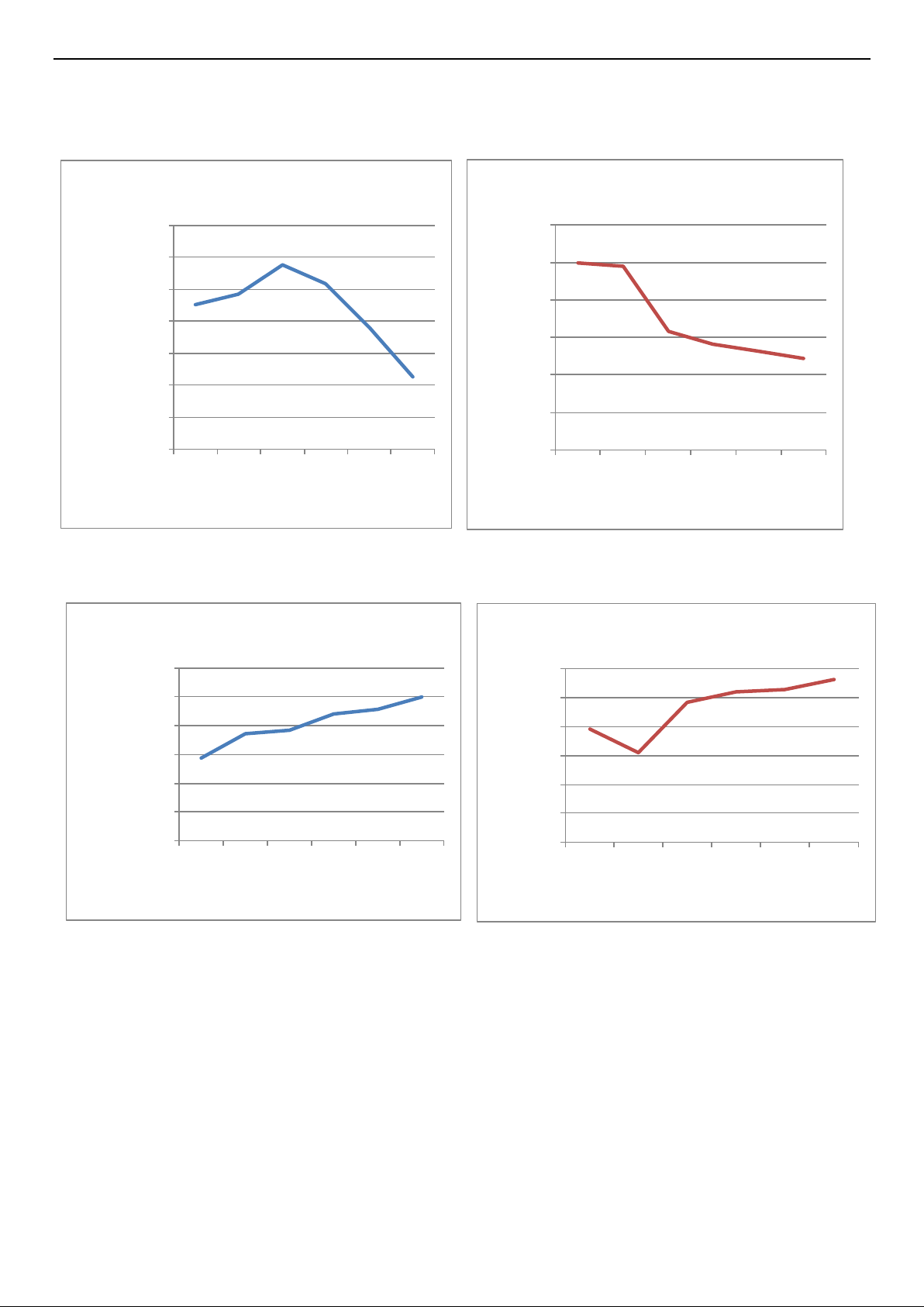
57
6-4. Performance Data
Temperature charts
95.00%
100.00%
105.00%
110.00%
115.00%
120.00%
125.00%
130.00%
20 25 30 35 40 43
Capacity Ratio
(%)
Outdoor Temp( ℃)
cooling
0.00
1.00
2.00
3.00
4.00
5.00
6.00
20 25 30 35 40 43
EER
Outdoor Temp( ℃)
cooling
0.00%
20.00%
40.00%
60.00%
80.00%
100.00%
120.00%
-15 -7 -5 2 7 12
Capacity Ratio
(%)
Outdoor Temp( ℃)
Heating
Indoor
Temp:
DB 20℃
0.00
0.50
1.00
1.50
2.00
2.50
3.00
-15 -7 -5 2 7 12
COP
Outdoor Temp( ℃)
Heating
Page 58

58
0.00
1.00
2.00
3.00
4.00
20 25 30 35 40 43
EER
Outdoor Temp( ℃)
cooling
0.00%
20.00%
40.00%
60.00%
80.00%
100.00%
120.00%
-15 -7 -5 2 7 12
Capacity Ratio
(%)
Outdoor Temp( ℃)
Heating
Indoor
Temp:DB
0.00
1.00
2.00
3.00
4.00
-15 -7 -5 2 7 12
COP
Outdoor Temp(℃)
Heating
Page 59

59
7. Electrical Characteristics
7-1. Print Circuit Board (Indoor & Outdoor)
Model
Indoor Unit
Outdoor Unit
+AST-09UW4RXE**00B
1951838
SD008-160705A
+AST-12UW4RXE**00B
1951838
SD008-160705A
+AST-18UW4RBA**00A
1951838
1878005
+AST-24UW4RDB**00A
1951838
1846941/1924721
+AST-09UW4RVE**00A
1951844
SD008-160705A
+AST-12UW4RVE**00A
1951844
SD008-160705A
+AST-18UW4RXA**00A
1951844
1878005
+AST-24UW4RBB**00B
1951838
1878005
+AST-09UW4RVE**00
1833235
SD008-160705A
+AST-12UW4RVE**00
1833235
SD008-160705A
+AST-18UW4RXA**00
1833235
1878005
+AST-24UW4RBB**00
1951838
1878005
AS-09UW4RYR**01A
2009223
SD008-160705A
AS-12UW4RYR**01A
2009223
SD008-160705A
AST-18UW4RXS**01
1995727
1952498
AST-24UW4RBT**01
1986288
1978975
+AST-09UW4RXU**00
2032199
SD008-180401A
+AST-12UW4RXU**00
2032199
SD008-180401A
+AST-09UW4RXV**00
2009223
SD008-180401A
+AST-12UW4RXV**00
2009223
SD008-180401A
Note: 1、 “ ** ” mean code of Front Panel
2、These colds are not spare parts’ cold, Please don’t use these colds to order spare parts,
Page 60

60
Model of indoor unit:
1995727
1986288
Page 61

61
1833235
1951838
Page 62

62
1951844
2032199
Page 63

63
2009223
Model of outdoor unit:
1878005/1952498
Page 64

64
1978975
SD008-160705A
Page 65

65
1924721
SD008-180401A
Page 66

66
7-2. Fan Motor
Drawings attached:
DG13G1-16、DG13G2-07
Test in resistance.
TOOL: Multimeter.
Test the resistance of the main winding. The indoor fan motor is fault if the resistance of
main winding 0(short circuit)or∞(open circuit).
Test in voltage
TOOL: Multimeter.
Insert screwdriver into to rotate indoor fan motor slowly for 1 revolution or over, and measure
voltage “YELLOW” and “GND” on motor. The voltage repeat 0V DC and 5V DC.
Notes:
1) Please don’t hold motor by lead wires.
2) Please don’t plug IN/OUT the motor connecter while po wer ON.
3) Please don’t drop hurl or dump motor against hard material. Malfunction may not be observed at
early stage after such shock. But it may be found later, this type of mishandling void our
warranty.
Page 67

67
Indoor DC Fan Motor
Outdoor DC Fan Motor
7-3. Temperature Sensor
Parameter table attached:
1. THE PARAMETER OF THE INDOOR COIL AND INDOOR ROOM SENSOR ,THE PARAMETER OF THE
OUTDOOR COIL AND OUTDOOR ENVIRONMENT SENSOR:
(R(0)=15k B(0/100)=3450)
Temperature(℃)
Resistance(k)
Voltage(V)
Temperature(℃)
Resistance(k)
Voltage(V)
-20
38.757
0.58143512
31
4.292
2.715076661
-19
36.844
0.60795346
32
4.137
2.76063657
-18
35.038
0.63530819
33
3.989
2.805589174
-17
33.331
0.66352684
34
3.847
2.850117358
-16
31.719
0.69257720
35
3.711
2.894109636
-15
30.196
0.72246147
36
3.58
2.937788018
-14
28.755
0.75321223
37
3.455
2.980713033
-13
27.392
0.78480857
38
3.335
3.023117961
Page 68

68
-12
26.103
0.81722911
39
3.219
3.065272268
-11
24.882
0.85051031
40
3.108
3.106725146
-10
23.727
0.88458737
41
3.001
3.147759536
-9
22.632
0.91951536
42
2.899
3.187898487
-8
21.594
0.95527085
43
2.801
3.227439565
-7
20.611
0.99179340
44
2.706
3.266717909
-6
19.678
1.02913875
45
2.615
3.305249514
-5
18.794
1.06721353
46
2.528
3.342947037
-4
17.954
1.10609872
47
2.444
3.380169671
-3
17.158
1.14565549
48
2.363
3.416856492
-2
16.401
1.18599135
49
2.286
3.45247766
-1
15.683
1.22696435
50
2.211
3.487894953
0
15
1.26865672
51
2.139
3.522585993
1
14.351
1.31098658
52
2.07
3.556485356
2
13.734
1.35393437
53
2.003
3.590032381
3
13.148
1.39741342
54
1.939
3.622673675
4
12.589
1.44157386
55
1.877
3.654865988
5
12.058
1.48618720
56
1.818
3.686036427
6
11.553
1.53125563
57
1.76
3.717201166
7
11.071
1.57689691
58
1.705
3.747244673
8
10.613
1.62286005
59
1.652
3.776658768
9
10.176
1.66928515
60
1.6
3.805970149
10
9.76
1.71601615
61
1.551
3.834009923
11
9.363
1.76311968
62
1.503
3.861880963
12
8.985
1.81043663
63
1.457
3.888973616
13
8.624
1.85805887
64
1.413
3.91524643
14
8.279
1.90597205
65
1.37
3.941267388
15
7.951
1.95387327
66
1.328
3.967019291
16
7.637
2.00204130
67
1.289
3.991234935
17
7.337
2.05033368
68
1.25
4.015748031
18
7.051
2.09859271
69
1.213
4.039284017
19
6.778
2.14682606
70
1.177
4.062450215
20
6.516
2.19524793
71
1.142
4.085229093
21
6.267
2.24333597
72
1.109
4.106941536
22
6.028
2.29151689
73
1.076
4.12888601
23
5.8
2.33944954
74
1.045
4.149715216
24
5.581
2.38741691
75
1.015
4.17007359
25
5.372
2.43506494
76
0.986
4.189944134
26
5.172
2.48247664
77
0.957
4.210004953
27
4.981
2.52951096
78
0.93
4.228855721
28
4.797
2.57653834
79
0.904
4.247168554
29
4.622
2.62291710
80
0.878
4.265640683
30
4.453
2.66931854
Note: the AD value in the table is calculated on the basis of the pull-down resistor is 5.1K.
Page 69

69
2. THE PARAMETER OF OUTDOOR COMPRESSOR TEMPERATURE SENSOR:
R(0)=187.25k B(0100)=3979)
Temperature
(℃)
Resistance(k)
Voltage(V)
Temperature
(℃)
Resistance
(k)
Voltage(V)
-20
542.867
0.06185563
51
19.907
1.273074475
-19
512.839
0.06543004
52
19.148
1.310312934
-18
484.672
0.06917993
53
18.422
1.348029498
-17
458.239
0.07311215
54
17.728
1.386170907
-16
433.423
0.07723358
55
17.065
1.424680494
-15
410.115
0.08155140
56
16.43
1.463624623
-14
388.213
0.08607312
57
15.822
1.502961719
-13
367.625
0.09080590
58
15.241
1.542579738
-12
348.264
0.09575738
59
14.684
1.582573078
-11
330.048
0.10093573
60
14.151
1.622834232
-10
312.904
0.10634837
61
13.64
1.663405088
-9
296.761
0.11200385
62
13.151
1.704175229
-8
281.556
0.11790981
63
12.682
1.745200698
-7
267.227
0.12407536
64
12.233
1.78637104
-6
253.72
0.13050821
65
11.802
1.827760456
-5
240.982
0.13721739
66
11.388
1.869364416
-4
228.965
0.14421140
67
10.992
1.910971223
-3
217.624
0.15149895
68
10.611
1.952788467
-2
206.917
0.15908889
69
10.246
1.994602839
-1
196.805
0.16699001
70
9.896
2.036415908
0
187.25
0.17521257
71
9.559
2.078366648
1
177.957
0.18402550
72
9.236
2.120229484
2
169.186
0.19319719
73
8.925
2.162162162
3
160.903
0.20273937
74
8.627
2.203928178
4
153.179
0.21252789
75
8.341
2.245558418
5
145.685
0.22297275
76
8.065
2.287251934
6
138.696
0.23368340
77
7.8
2.328767123
7
132.086
0.24480509
78
7.546
2.369998606
8
125.833
0.25634646
79
7.301
2.411176512
9
119.916
0.26831655
80
7.065
2.452217815
10
114.315
0.28072493
81
6.843
2.492120501
11
109.01
0.29358432
82
6.624
2.532777116
12
103.984
0.30690352
83
6.414
2.573028606
13
99.222
0.32068816
84
6.212
2.612972641
14
94.708
0.33494897
85
6.017
2.652726847
15
90.427
0.34969710
86
5.829
2.692216328
16
86.366
0.36494000
87
5.648
2.731362468
17
82.512
0.38068793
88
5.474
2.770083102
18
78.854
0.39694585
89
5.306
2.808524698
19
75.381
0.41372093
90
5.144
2.846617549
20
72.082
0.43102355
91
4.988
2.884289108
21
68.948
0.44885674
92
4.837
2.921715219
Page 70

70
22
65.968
0.46723835
93
4.692
2.958579882
23
63.136
0.48615877
94
4.552
2.995066949
24
60.443
0.50562884
95
4.417
3.031113488
25
57.88
0.52566481
96
4.286
3.066931265
26
55.367
0.54691396
97
4.161
3.10190676
27
52.978
0.56877112
98
4.039
3.13682074
28
50.707
0.59123237
99
3.922
3.171050177
29
48.547
0.61430611
100
3.776
3.214826021
30
46.492
0.63799445
101
3.703
3.237170332
31
44.537
0.66229036
102
3.602
3.268602192
32
42.676
0.68720188
103
3.501
3.300650422
33
40.904
0.71272849
104
3.409
3.33039475
34
39.217
0.73885738
105
3.317
3.360680043
35
37.609
0.76561057
106
3.228
3.390506582
36
36.077
0.79296593
107
3.141
3.420179056
37
34.616
0.82093877
108
3.058
3.448975451
38
33.224
0.84949031
109
2.977
3.477549351
39
31.895
0.87866649
110
2.899
3.505516033
40
30.628
0.90841082
111
2.823
3.533201704
41
29.419
0.93873381
112
2.749
3.56058226
42
28.264
0.96965549
113
2.678
3.587254695
43
27.162
1.00111890
114
2.609
3.613561484
44
26.109
1.03315203
115
2.542
3.639477628
45
25.103
1.06573050
116
2.477
3.664977902
46
24.142
1.09883007
117
2.414
3.6900369
47
23.223
1.13246511
118
2.353
3.714629083
48
22.345
1.16658089
119
2.294
3.738728832
49
21.505
1.20120120
120
2.237
3.762310501
50
20.701
1.23631868
Note: the AD value in the table is calculated on the basis of the pull-down resistor is 6.8K.
Page 71

71
7-4. Compressor
Drawings attached:
DC
INVERTER
CONTROLLER
&
RU()
SV()
TW()
OVERLOAD PROTECTION
POWER
Test in resistance.
TOOL: Multimeter.
Test the resistance of the winding. The compressor is fault if the resistance of winding 0(short
circuit)or∞(open circuit)
Familiar trouble: 1)Compressor motor lock. 2)Discharge pressure value approaches static pressure
value .3)Compressor motor winding abnormality.
Notes:1)Don’t put a compressor on its side or turn over.
2) Please assembly the compressor in your air conditioner rapidly after removing the plugs. Don’t
place the comp. In air for along time.
3) Avoiding compressor running in reverse caused by connecting electrical wire incorrectly.
4) Warning! In case AC voltage is impressed to compressor, the compressor performance will be
lower because of its rotor magnetic force decreasing.
7-5. Electric Reactor
Drawings attached:
Familiar error:
1)Sound abnormality
2)Insulation resistance disqualification.
L
Page 72

72
7-6. Room Card Control, Fire Protection, ON/OFF Function (Optional)
7-6-1.Instructions for the function setting of room card control, fire protection, ON/OFF function.
1. Factory setting
ON/OFF function is tacitly approved to be invalid when out of factory while both the room card control and fire protection
functions are valid.
In case of using or cancelling the room card control / fire protection / (ON/OFF) function, use the wire controller to
modify the parameters of indoor unit.
2. Function introduction
1) Room card control: a kind of control mode to control the machine startup & shutdown based on the on & off state of
the room card control port.
2) Fire protection: a kind of control mode to control the machine startup & shutdown based on the on & off state of the fire
protection port.
3) ON/OFF function: a kind of special control mode to achieve the control of indoor unit startup & shutdown based on the
input state of the fire protection port of the indoor unit (no other way can control startup & shutdown) and output the fault
status of indoor unit through OUT INPUT port.
3. Function setting
Fig.1 OUT INPUT Fig.2 short wiring Fig.3 output line
Fig.4 Hardware connection diagram
Pins of the OUT INPUT CN16 socket shown in the electrical wiring diagram of Fig 1 are tacitly approved to be in short
Page 73

73
circuit state under the factory state (an external short circuit plug shown as Figure 2).
(Illustration: the socket number in circuit is subject to the actual serial number of PCB.)
1) When using the room card control, the user cuts off the short wire shown in Figure 2 and connects the red lines to the
control switch (supplied by user), and the connecting wire should be 22AWG or above specification. The switch is closed
under normal conditions and off under abnormal conditions.
2) When using the fire protection , the user cuts off the short wire shown in Figure 2 and connects the White lines to the
control switch (supplied by user), and the connecting wire should be 22AWG or above specification. The switch is closed
under normal conditions and off under abnormal conditions.
3) When using the ON/OFF function, the user cuts off the short wire shown in Figure 2 and connects the White lines the
ON/OFF control switch (supplied by user), and the connecting wire should be 22AWG or above specification. In normal
conditions, the machine starts once the switch is closed and the machine shuts down once the switch is off.
4 Setting method
This machine defaults that the room card control is effective, which can be switched between the room card control and
ON/OFF function through wire controller. The specific operations are as follows:
Fig. 1
Fig.2 YXE-C01U/ YXE-C02U(E) Fig.3 YXE -D01U(E)
Page 74

74
Fig.4 YXE-A03U(E)
The EE address number of ON/OFF function is 25:first enter the parameter number 17, and then adjust to the EE address number 25.
Exhibit 1: Built-in EE settings combination
EE DATA
Red Line (1+2)
White Line (2+3)
0
Void
Void
1
Hotel Room Card Control
Void
2
Void
Fire Protection Control
3
Hotel Room Card Control
Fire Protection Control
4
Void
ON/OFF
Reading and writing EE operations through wire remote controller are as follows:
(1) Operations: In any state, hold down both “MODE” button and “ADD.FUNC.” button for 3 seconds to enter read and
write parameters.
Result: The buzzer makes a functional sounds. On display screen, the symbol and the parameter number flash at
the same time.
Note: For YXE-D01U(E), replace “ADD.FUNC.” button with “FUNC” button.
Note: For YXE-A03U(E), replace “ADD.FUNC.” button with “Fan speed” button.
(2) Operations: In a state of that, The symbol and the parameter number flash at the same time,press button or
button。
Result: On display screen, the parameter number increases or decreases by 1 correspondingly (0-25), and the
parameter data changes correspondingly.
(3) Operations: In a state of that, the symbol and the parameter number 17 flash at the same time,press “ENTER”
button to enter the EE reading.
Result: On display screen, the symbol does not flash, and the EE address flashes.
Note: For YXE-A03U(E), replace “ENTER” button with “Timer” button.
(4) Operations: In a state of that, the symbol does not flash, and the EE address flashes, press button or
button.
Result: On display screen, the EE address increases or decreases by 1 (0-255) correspondingly, and the parameter
data changes correspondingly.
Page 75

75
(5) Operations: In a state of that, the symbol does not flash, and the EE address number 25 flash, press “ENTER”
button to enter the EE writing.
Result: On display screen, the symbol and the EE address number 25 do not flash, and the function code
corresponding to the EE address flashes.
Note: For YXE-A03U(E), replace “ENTER” button with “Timer” button.
(6) Operations: In a state of that, the symbol and the EE address number 25 do not flash, and the function code
corresponding to the EE address flashes, press button or button.
Result: On display screen, the function code corresponding to the EE address increases or decreases by 1.
(7) Operations: In a state of that, the symbol and the EE address number 25 do not flash, and the function code
corresponding to the EE address flashes, press “ENTER” button.
Result: On display screen, the symbol does not flash, and the EE address number 25 flashes to display the
function code of EE after modification.
Note: For YXE-A03U(E), replace “ENTER” button with “Timer” button.
(8) Press “ON/OFF” button or “CANCEL” button to exit.
Note: For YXE-A03U(E), Press “ON/OFF” button to exit.
7-6-2.Instructions for the function setting of room card control, fire protection, ON/OFF function.
1. Factory setting
ON/OFF function is tacitly approved to be invalid when out of factory while both the room card control and fire
protection functions are valid.
In case of using or cancelling the room card control / fire protection / (ON/OFF) function, use the wire controller to
modify the parameters of indoor unit.
2. Function introduction
(1) Room card control: a kind of control mode to control the machine startup & shutdown based on the on & off state
of the room card control port.
(2) Fire protection: a kind of control mode to control the machine startu p & shutdown based on the on & off state of
the fire protection port.
(3) ON/OFF function: a kind of special control mode to achieve the control of indoor unit startup & shutdown based
on the input state of the fire protection port of the indoor unit (no other way can control startup & shutdown) and output
the fault status of indoor unit through OUT INPUT port.
3. Function setting
3.1 Hardware connection
Fig.1 electrical wiring diagram
Page 76

76
Fig.2 short wiring (old)
Fig.3 main control board
Fig.2 short wiring (new) Fig.3 main control board
Fig.4 output line
3 pins of the OUT INPUT CN16 socket shown in the electrical wiring diagram of Figure 1 are tacitly approved to be
in short circuit state under the factory state (an external short circuit plug shown as Figure 2), and the OUT INPUT
CN16 socket of main control board is shown as Figure 3.
(Illustration: the socket number in circuit is subject to the actual serial number of PCB.)
4) When using the room card control or fire protection , the user cuts off the short wire shown in Figure 2 and connects
the red line and the black line to the control switch (supplied by user), and the connecting wire should be 22AWG
or above specification. The switch is closed under normal conditions and off under abnormal conditions.
5) When using the ON/OFF function, the user cuts off the short wire shown in Figure 2 and connects the black line
and the white line to the ON/OFF control switch (supplied by user), and the connecting wire sho uld be 22AWG or
above specification. In normal conditions, the machine starts once the switch is closed and the machine shuts
down once the switch is off.
Page 77

77
Fig.5 Hardware connection diagram
Master slave
1、Indoor unit plan:
1)Two indoor units must are the Universal units,and have the ON/OFF function ;
2)Must set ON/OFF function;
2、Set step:
1)Set the indoor unit mode,fan speed ,temp. and flap angle;
2)Use the wire control remote to set ON/OFF function ;
3)Cut the white line,and connect the external controller;
4)Output line connect the external controller;
5)Do the same work to another indoor unit.
Page 78

78
Master slave connection diagram
3.2 Timing se quence description:
(1) Room card control:
1) Control of room card disconnection: the air conditioner shall be shut down after the room card control signal is
disconnected. In this state, the indoor unit can’t be started. If the user performs starting operation, the wire controller
shall not respond and displays power -off.
2) Control of room card connection: after the short circuit of room card control interface, release power-on
restrictions, the wire controller maintains power-off and the startup & shutdown control is effective.
(2) Fire protection
1) Access to fire protection: the air conditioner shall be shut down after the fire protection signal is disconnected.
In this state, the indoor unit can’t be started. If the user performs starting operation, the wire controller shall not respo nd
and displays power-off.
2) Cancellation of fire protection: after the short circuit of fire protection signal, release power -on restrictions, the
wire controller maintains power -off and the startup & shutdown control is effective.
(3) ON/OFF function
1) In the situation where ON/OFF function is effect, the port is closed and in short circuit, the indoor unit starts;
the indoor unit shuts down once the port is disconnected;
2) Other operation information (such as mode, air speed, air door, etc.) except for startup & shutdown can be set
through the wire controller, remote-controller and WIFI module;
3) In the mode of ON/OFF function, wire controller, remote-controller, WIFI module and room card control cannot
control the machine startup & shutdown, and nor can in the mode of the timing or sleep function.
Page 79

79
4) There will be 12V signal output when machine fault occurs.
3.3 Relative priorities of instructions
ON/OFF function has the highest priority. The room card control shall be invalid when ON/OFF function is
effective.
The room card control and fire protection can not be selected at the same time, only one can be selected.
7-7. Wiring Remote Controller
Model
Installation Manual
Use And Installation Instructions
YXE-C01U
1813253
1813254
YXE-D01U(E)
1898797
1898796
YXE-C02U(E)
1844538
1844539
YXE-A03U(E)
Not available
1967341
Note: Installation Manual and Use And Installation Instructions are separate documents.
Page 80

80
8.Trouble Shooting
8-1. Error Code Table
1.Indication on the outdoor unit:
When the unit has the following trouble and the compressor stops running, The LED of outdoor control board
will show the error sequence automatically:
NOTE:
★:
LIGHT O:FLASH
:
OFF
Error
code
Outdoor Failure
Description
LED1
LED2
LED3
the root cause my be one of the following
Mark description: the lights flash every second for the following faults
Normal
Outdoor coil
temperature
sensor in trouble
★ ★
a. the outdoor coil sensor connect loose;
b. the outdoor coil temperature sensor is failure;
c. the outdoor control board is failure
Compressor
exhaust
temperature
sensor in trouble
★
a. the compressor exhaust temperature sensor
connect loose;
b. the compressor exhaust temperature sensor is
failure;
c. the outdoor control board is failure
Communication
failure between the
indoor unit and
outdoor unit
O
a. the communication cable connect loose;
b. the communication cable is failure;
c. the connection between the filter board and the
outdoor control board is incorrect or loose;
d. the connection between the filter board and the
terminal is incorrect or loose;
e. the indoor control board is failure;
f. the PFC board is failure;
g. the power board is failure; h. the outdoor
control board is failure.
Current overload
protection
★
O
a. the fan motor run abnormally;
b. the condenser or and evaporator is dirty;
c. the air inlet and outlet is abnormally
Maximum current
protection
★ O ★
a. the outdoor control board is short circuit;
b. the drive board is short circuit;
c. the other components is short circuit
Communication
trouble between
outdoor unit and
driver
★
★
a. the connection wires connect loose
b. the outdoor board or drive board is failure;
Outdoor EEPROM
in trouble
★ ★ ★
a. he EEPROM chip is loose;
b. the EEPROM chip inserted with opposite
direction;
Page 81

81
c. the EEPROM chip is failure
Compressor
exhaust
temperature too
high protection
O
★
a. the compressor exhaust temperature sensor is
failure;
b. the refrigerant of the unit is not enough
Outdoor ambient
temperature
sensor in trouble
★
★
a. the outdoor ambient temperature sensor
connect loose;
b. the outdoor ambient temperature sensor is
failure;
c. the outdoor control board is failure
Compressor shell
temperature too
high protection
★
O
a. the compressor exhaust temperature sensor
connect loose
b. the refrigerant of the unit is not enough
Anti-freeze
protection with
cooling or overload
protection with
heating in indoor
unit
O
O
a. the indoor coil temperature sensor connect
loose;
b. the indoor coil temperature sensor is failure;
c. the indoor control board is failure
d. the refrigerant system is abnormal.
Compressor drive
in trouble
O O
a. the outdoor drive board is failure;
b. the compressor is failure
c. the outdoor control board is failure
Outdoor fan motor
locked rotor
protection
O
O
★
a. the connection of the outdoor fan motor is
loose; b. there are something
block the outdoor fan;
c. the fan motor is failure;
d. the outdoor control board is failure
Outdoor coil antioverload protection
with cooling
★
a. the refrigerant is too much;
b. the outdoor fan motor is failure;
c. the outdoor fan is broken;
d. the condenser is dirty;
e. the air inlet and air outlet of the indoor unit and
the outdoor unit is not normally
Page 82

82
IPM module
protection
O
a. The IPM board is failure;
b. The outdoor fan is broken;
c. The outdoor fan motor is failure;
d. The outdoor fan has been blocked ;
e. The condenser is dirty;
f. The outdoor unit has been installed without
standard.
PFC protection
O
a. the PFC is failure;
b. the outdoor drive board is failure
Compressor pre
heating process
O ★ O
it is normal mode in cold weather
Chip in outdoor
board in trouble
★
O
a. Using the wrong drive board;
b. Using the wrong compressor.
AC voltage higher
or lower protection
★
★
O
a. the supply voltage is higher or lower than
normal;
b. the inner supply voltage of the unit is higher or
lower than normal
DC compressor
start failure
O
O
a. the outdoor drive board is failure;
b. the compressor is failure
Outdoor ambient
temperature too
low protection
★
O
O
a、Outdoor ambient temperature too low
Mark description: the lights flash every two seconds for the following faults
Protection against
overheated outdoor
radiator
a. Radiator sensors fail
b. Detection circuit of the sensor on the
control panel fails
Protection of the
system against too
high pressure
a. The pressure switch fails
b. The pressure detection switch on the control
panel fails
c. The measured value of the system pressure
exceeds the limit
When the compressor is in ope ration:
Mark description: ★:Light:Flash :Off; the flash cycle is 1S
No.
LED1
LED2
LED3
Reasons for the current operating fre quency
of the compressor is limited
1
Normal frequency rising and decreasing, no
limitation
2
★
Frequency decreasing or prohibition of frequency
rising caused by over-current
3 ★
★
Frequency decreasing or prohibition of frequency
rising caused by anti-freezing of refrigeration or
anti-overload in heating
Page 83

83
4
★ ★
Frequency decreasing or prohibition of frequency
rising caused by too high compressor discharge
temperature
5
Limit to the max operating frequency caused by
too low power voltage
6 ★ ★
★
Operation at fixed frequency (in the case of
capability measuring or compulsory operation at
fixed frequency)
7
Protective frequency decreasing against outdoor
overload (overpower, over frequency conversion
rate, over torque, detection of DC under -voltage)
8
★
Frequency decreasing caused by indoor and
outdoor communication fault
9 ★
Frequency decreasing or prohibition of frequency
rising protection against overload of outdoor
coiled pipe
10 ★
Frequency decreasing or prohibition of frequency
rising for power-saving when it is being used
simultaneously with other appliances
2.Indication by the indoor unit:
2.1.The 7-segment tube of the indoor display board will show the error code automatically when the unit has
the following trouble:
Error
code
Power
Timer
Running
Sleep
Remark:★Light o Flash x OFF
1 2 3
4
Content
Remark
The root cause is may be
one of the following
EA
the error code
will display when
the
communication
between display
board and
control board
have in trouble
a. The connection
between the
display board and control
board is loose;
b. The indoor control board
is failure.
c. The wiring of the display
board is failure.
2.2.When the unit has the following trouble and the compressor stops running, press the sleep button on the
remote controller for 4 times in ten seconds and the 7-segment tube of the display board will show the error code as
the following, if two malfunction happened at the same time, it need press the sleep button for 4 times again, the LED
will show the other error code.
Refer to the remote controller which the sleep key can set into 4 differen t combination ways (Hisense's new
design remote controller), when using to check the error codes need exit all the sleep mode first and then press the
sleep button 10 times in ten seconds instead of 4 times.
NOTE: If the troubleshooting inquiry display by 7-segment tube, then the error code will be displayed, otherwise
only the LED of the display board can show.
Error
code
Running
Timer
Sleep
Power
Remark:★Light o Flash x OFF
1 2 3
4
Content
Remark
The root cause is may be one
of the following
Page 84

84
1 x o x x
The failure for
temperature
sensor of
outdoor coil
a. The outdoor temperature
sensor loose;
b. the outdoor temperature
sensor is failure;
c. The indoor control board is
failure
2
★
Compressor
exhaust
temperature
sensor in
trouble
a. the compressor exhaust
temperature sensor connect
loose;
b. the compressor exhaust
temperature sensor is failure;
c. the outdoor control board is
failure
5
★
IPM module
protection
a. The IPM board is failure;
b. The outdoor fan is broken;
c. The outdoor fan motor is
failure;
d. The outdoor fan has been
blocked ;
e. The condenser is dirty;
f. The outdoor unit has been
installed without standard.
6
★
★
AC voltage
higher or lower
protection
a. the supply voltage is higher
or lower than normal;
b. the inner supply voltage of
the unit is higher or lower than
normal
7
★
★
Communication
failure between
the indoor unit
and outdoor
unit
a. the communication cable
connect loose;
b. the communication cable is
failure;
c. the connection between the
filter board and the outdoor
control board is incorrect or
loose;
d. the connection between the
filter board and the terminal is
incorrect or loose;
e. the indoor control board is
failure;
f. the PFC board is failure;
g. the power board is failure;
h. the outdoor control board is
failure.
8
★
★ ★
Current
overload
protection
a. the fan motor run abnormally;
b. the condenser and
evaporator is dirty;
Page 85

85
c. the air inlet and outlet is
abnormally
9
Maximum
current
protection
a. the outdoor control board is
short circuit;
b. the drive board is short
circuit;
c. the other components is
short circuit
10
★
Communication
trouble
between
outdoor unit
and driver
a. the connection wires connect
loose
b. the outdoor board or drive
board is failure;
11
★
Outdoor
EEPROM in
trouble
a. the EEPROM chip is loose;
b. the EEPROM chip inserted
with opposite direction;
c. the EEPROM chip is failure
12
★
★
Outdoor
ambient
temperature
too low
protection
Outdoor ambient temperature
too low
13
★
Compressor
exhaust
temperature
too high
protection
a. the compressor exhaust
temperature sensor is failure;
b. the refrigerant of the unit is
not enough
14
★
★
Outdoor
ambient
temperature
sensor in
trouble
a. the outdoor ambient
temperature sensor connect
loose;
b. the outdoor ambient
temperature sensor is failure;
c. the outdoor control board is
failure
15
★ ★
Compressor
shell
temperature
too high
protection
a. the compressor exhaust
temperature sensor connect
loose
b. the refrigerant of the unit is
not enough
16
Anti-freeze
protection with
cooling or
overload
protection with
heating in
a. the indoor coil temperature
sensor connect loose;
b. the indoor coil temperature
sensor is failure;
c. the indoor control board is
failure
d. the refrigerant system is
abnormal.
Page 86

86
17
PFC protection
a. the PFC is failure;
b. the outdoor drive board is
failure
18
DC compressor
start failure
a. the outdoor drive board is
failure;
b. the compressor is failure
19
Compressor
drive in trouble
a. the outdoor drive board is
failure;
b. the compressor is failure
c. the outdoor control board is
failure
20
★
Outdoor fan
motor locked
rotor protection
a. the connection of the outdoor
fan motor is loose;
b. there are something block
the outdoor fan;
c. the fan motor is failure;
d. the outdoor control board is
failure
21
Outdoor coil
anti-overload
protection with
cooling
a. the refrigerant is too much;
b. the outdoor fan motor is
failure;
c. the outdoor fan is broken;
d. the condenser is dirty;
e. the air inlet and air outlet of
the indoor unit and the outdoor
unit is not normally
22
Compressor
pre heating
process
it is normal mode in cold
weather
24
Chip in outdoor
board in trouble
a. Using the wrong drive board;
b. Using the wrong compressor.
26
Overheated
outdoor radiator
a. Radiator sensor fails
b. Detection circuit of the
sensor on the control
panel fails
27
Protection
against too high
system
pressure
a. The pressure switch
fails
b. The pressure detection
switch on the control panel
fails
c. The measured value of
system pressure exceeds
the limit
33 o x x ★
The failure for
temperature
sensor of
indoor room
a. The indoor room temperature
sensor loose;
b. The indoor room temperature
sensor is failure;
Page 87

87
c. The indoor control board is
failure.
34 o x ★ x
The failure for
temperature
sensor of
indoor coil
temperature
a. The indoor coil temperature
sensor loose;
b. The indoor coil temperature
sensor is failure;
c. The indoor control board is
failure.
36
★
★
Communication
failure between
the indoor unit
and outdoor
unit
a. the communication cable
connect loose;
b. the communication cable is
failure;
c. the connection between the
filter board and the outdoor
control board is incorrect or
loose;
d. the connection between the
filter board and the terminal is
incorrect or loose;
e. the indoor control board is
failure;
f. the PFC board is failure;
g. the power board is failure;
h. the outdoor control board is
failure.
38 o ★ ★ ★
Indoor
EEPROM
failure
a. The EEPROM chip loose;
b. The indoor control board is
failure
39 o x ★ ★
Indoor fan
motor run
abnormally
a. There are something block
the indoor fan motor;
b. The fan motor cord connect
loose;
c. The fan motor is failure;
d. The indoor control board is
failure
41 ★ ★ o ★
The failure for
Indoor
grounding
protective
The indoor control board is
failure
2.2 LED display
Error
code
Sleep
Timer
Running
Remark:★Light Flash x OFF
1 2 3
Content
Remark
The root cause is may be one of
the following
0
Normal
Page 88

88
1
★ ★
The failure for
temperature
sensor of
outdoor coil
a. The outdoor temperature sensor
loose;
b. The outdoor temperature sensor
is failure;
c. The indoor control board is
failure
2
★
x
Compressor
exhaust
temperature
sensor in
trouble
a. the compressor exhaust
temperature sensor connect loose;
b. the compressor exhaust
temperature sensor is failure;
c. the outdoor control board is
failure
5
★
x
IPM module
protection
a. The IPM board is failure;
b. The outdoor fan is broken;
c. The outdoor fan motor is failure;
d. The outdoor fan has been
blocked ;
e. The condenser is dirty;
f. The outdoor unit has been
installed without standard.
6
x x
AC voltage
higher or lower
protection
a. the supply voltage is higher or
lower than normal;
b. the inner supply voltage of the
unit is higher or lower than normal
7
★
★
x
Communication
failure between
the indoor unit
and outdoor
unit
a. the communication cable
connect loose;
b. the communication cable is
failure;
c. the connection between the filter
board and the outdoor control
board is incorrect or loose;
d. the connection between the filter
board and the terminal is incorrect
or loose;
e. the indoor control board is
failure;
f. the PFC board is failure;
g. the power board is failure;
h. the outdoor control board is
failure.
8
Current
overload
protection
a. the fan motor run abnormally;
b. the condenser and evaporator is
dirty;
c. the air inlet and outlet is
abnormally
9
Maximum
current
protection
a. the outdoor control board is
short circuit;
b. the drive board is short circuit;
Page 89

89
c. the other components is short
circuit
10
★
x
x
Communication
trouble
between
outdoor unit
and driver
a. the connection wires connect
loose
b. the outdoor board or drive
board is failure;
11
x
x
Outdoor
EEPROM in
trouble
a. the EEPROM chip is loose;
b. the EEPROM chip inserted with
opposite direction;
c. the EEPROM chip is failure
12
Outdoor
ambient
temperature
too low
protection
Outdoor ambient temperature too
low
13
x ★
Compressor
exhaust
temperature
too high
protection
a. the compressor exhaust
temperature sensor is failure;
b. the refrigerant of the unit is not
enough
14
★ ★
Outdoor
ambient
temperature
sensor in
trouble
a. the outdoor ambient temperature
sensor connect loose;
b. the outdoor ambient temperature
sensor is failure;
c. the outdoor control board is
failure
15
x
★
Compressor
shell
temperature
too high
protection
a. the compressor exhaust
temperature sensor connect loose
b. the refrigerant of the unit is not
enough
16
★ x ★
Anti-freeze
protection with
cooling or
overload
protection with
heating in
a. the indoor coil temperature
sensor connect loose;
b. the indoor coil temperature
sensor is failure;
c. the indoor control board is failure
d. the refrigerant system is
abnormal.
17
x ★ x
PFC protection
a. the PFC is failure;
b. the outdoor drive board is failure
18
x
★
★
DC compressor
start failure
a. the outdoor drive board is failure;
b. the compressor is failure
Page 90

90
19
x
★
Compressor
drive in trouble
a. the outdoor drive board is failure;
b. the compressor is failure
c. the outdoor control board is
failure
20
★ x
Outdoor fan
motor locked
rotor protection
a. the connection of the outdoor fan
motor is loose;
b. there are something block the
outdoor fan;
c. the fan motor is failure;
d. the outdoor control board is
failure
21
x
x
Outdoor coil
anti-overload
protection with
cooling
a. the refrigerant is too much;
b. the outdoor fan motor is failure;
c. the outdoor fan is broken;
d. the condenser is dirty;
e. the air inlet and air outlet of the
indoor unit and the outdoor unit is
not normally
22
Compressor
pre heating
process
it is normal mode in cold weather
24
Chip in outdoor
board in trouble
a. Using the wrong drive board;
b. Using the wrong compressor.
26
Overheated
outdoor radiator
a. Radiator sensor fails
b. Detection circuit of the
sensor on the control panel
fails
27
Protection
against too high
system
pressure
a. The pressure switch fails
b. The pressure detection switch
on the control panel fails
c. The measured value of
system pressure exceeds the
limit
33
★
The failure for
temperature
sensor of
indoor room
d. The indoor room temperature
sensor loose;
e. The indoor room temperature
sensor is failure;
f. The indoor control board is
failure.
34
x
The failure for
temperature
sensor of
indoor coil
temperature
d. The indoor coil temperature
sensor loose;
e. The indoor coil temperature
sensor is failure;
f. The indoor control board is
failure.
36
★
Communication
failure between
a. the communication cable
connect loose;
Page 91

91
the indoor unit
and outdoor
unit
b. the communication cable is
failure;
c. the connection between the filter
board and the outdoor control
board is incorrect or loose;
d. the connection between the filter
board and the terminal is incorrect
or loose;
e. the indoor control board is
failure;
f. the PFC board is failure;
g. the power board is failure;
h. the outdoor control board is
failure.
38
x
Indoor
EEPROM
failure
c. The EEPROM chip loose;
d. The indoor control board is
failure
39
★
Indoor fan
motor run
abnormally
a. There are something block the
indoor fan motor;
b. The fan motor cord connect
loose;
c. The fan motor is failure;
d. The indoor control board is
failure
41
x
x
★
The failure for
Indoor
grounding
protective
The indoor control board is failure
The failure is detected when the room temperature sensor broken or shorted over 5 sec.
The failure is detected when the temperature sensor of heater exchange broken or shorted over 5 sec.
The failure is detected when each setting data is not match after the EEPPOM self -check two times.
The failure is occur when the grounding signal is not detected after the appliance power ON.
Page 92

92
8-2. Test the jumper terminals
Note:
When the whole machine is powered up, if the external unit does not work, to rule out the
communications failures, adopt screening method such as short circuit on the jumper terminals to see if the
external unit can be started normally or similar method.
There are two blue terminals on the outdoor control panel, as shown above.
Application: Short out the terminals, and power up the outdoor unit, then the outdoor unit may run
independently. It can be determined that there is no internal and external communication faults.
When the environment temperature is lower than 18℃, you can't run the unit under the cool mode, but if you need
run the unit at this moment ,such as add the gas or do more test,
at this moment you can use this function,
Under this function, the outdoor motor and compressor will be forced to run until reaching a fixed frequency
(general is 50~55Hz).
8-3. Trouble Diagnosis of Protection
Protection diagnosis of the complete machine (all types of protection during operation, i.e.
under-voltage, over-voltage and overcurrent protection)
Note: List all types of protection that may occur to the complete machine and describe the conditions and
signs of the start, course and end of such protection.
Voltage protection
Protection against AC input over-voltage/under-voltage
1.Conditions for protection against AC inp ut over-voltage/under-voltage:
If the input AC voltage is greater than “protective over-voltage value” or less than “protective under-
voltage value” for five seconds, over-voltage/under-voltage protection tarts.
2.Protection actions against AC input ove r-voltage/under-voltage
The system stops operation.
3. Conditions for ending AC input over-voltage/under-voltage:
If the input AC voltage is lower than “the protective over-voltage value” -10V, or higher than “the
protective under-voltage value” +10V, the over-voltage/under-voltage protection will be released.
Curre nt protection:
1.Protection against over-current
Conditions for over-current protection: if the current is equal to or greater than “current value for starting the
refrigeration current protection (E2 value)” for six seconds, over-current protection starts.
Protection actions against over-current: indoor display screen and outdoor indicator give indications, the
Page 93

93
compressor and outdoor fan stop, but indoor fan runs normally.
Condition for ending over-current protection: when the current drops below “current value for releasing the
refrigeration current protection (E2 value)”, over-current protection will be released.
2.Frequency decreasing for over-current
Conditions for over-current fre quency decreasing: if the current is equal to or greater than “current value for
starting the refrigeration current protective frequency decreasing (E2 value) ”, over-current frequency
decreasing starts.
Over-current frequency decreasing actions: the compressor will decrease frequency at rate of (E2
value)Hz/S. The indoor and outdoor fans run.
Conditions for ending over-current fre quency decreasing: when the current drops below “current value for
starting the refrigeration current protective prohibition of frequency rising (E2 value)”, over-current under-
clocking will be released.
3.Prohibition of frequency increasing of compressor exhausting
Conditions for prohibition of frequency rising of compressor discharge
Condition 1: in the case of frequency decreasing of compressor discharge, the discharge temperature of the
compressor drops below X4℃.
Condition 2: in normal operation, the discharge temperature of compressor reaches X5 ℃.
Either of the above two conditions is met, prohibition of frequency rising of compressor d ischarge begins.
Actions relates to prohibition of frequency rising of compressor discharge: the frequency of compressor
maintains at the current level, which may decrease as the case requires while cannot rise. The indoor and
outdoor fans run.
Condition for ending prohibition of frequency rising of compressor discharge: if the tempe rature of
compressor discharge drops below X6℃, prohibition of frequency rising of compressor discharge will be
released.
4. Prohibition of frequency for anti-overload of outdoor coiled pipe
Condition for anti-overload prohibition of frequency of outdoor coiled pipe: in the case of anti-overload
frequency decreasing of outdoor coiled pipe, anti-overload prohibition of frequency of the unit begins when
the temperature of outdoor coiled pipe drops below “the anti-overload frequency decreasing temperature of
outdoor coiled pipe”.
Actions relates to anti-overload prohibition of frequency of outdoor coiled pipe: the frequency of compressor
maintains at the current level, which may decrease as the case requires while cannot rise. The indoor and
outdoor fans run.
Condition for ending anti-overload prohibition of frequency of outdoor coiled pipe: if the temperature of
outdoor coiled pipe drops below “temperature to release the anti-overload state of outdoor coiled pipe”, anti-
overload prohibition of frequency of outdoor coiled pipe will be released.
Page 94

94
8-4. Trouble Diagnosis of Compressor
Judging the connecting terminals of inverter compressor:
It is impossible to identify terminals U, V and W of inverter compressor with multi -meter. Just connect the
terminals in the same way as the original unit when replacing the compressor. A wrong connection will lead to
reverse and loud noise of the compressor.
Resistance of compressor coil:
Measure the resistance between any two terminals, which are about a few Ohms, three phase s having
the same resistance.
8-5. Trouble Diagnosis of Electric Filter Board
Visual examination: as the circuit is simple, the connection may be checked visually to see whether any
loose or poor connection.
Voltage test: the voltage at the input end shall be the same as the voltage at the output end.
Page 95

95
8-6. Trouble Diagnosis of Electric Communication
Step one: to determine whether the connecting cables and tether cables of indoor/outdoor units are correctly
wired. If not, change wiring order and test connection.
Step two: to determine whether there is loose connection.
Fasten the connection in the case of loose connection and then conduct verification.
Step three: measure the voltage between SI and N with multi-meter and see whether the voltage fluctuates
between 0V and 24V. Please directly replace indoor and outdoor control boards if there are not voltage
fluctuations.
Page 96

96
8-7. Diagnosis and Solution
1.
Does the screen
display normally?
Switch on the
power supply
Is the fuse
(5A/250V) burn?
Are the wires
poorly
connected?
Check the input
voltage and output
voltage correct or not
Indoor control board is fault
Replace it.
No
No
No
No
Does it receive the
remote controller
signal?
Is the remote
controller
setting right?
Check the code
Replace the batteries
Retry remote operation.
If not good,replace
remote controller
Is the remote
controller in good
condition?
Make sure all wires
are connected
correctly
Replace the
display board
Replace the
display board
Replace the
indoor control
board
Yes
Yes
No
Yes
Yes
No
Yes
Yes
Yes
Error code 39
Indoor fan motor trouble
Set the air conditioner
operate in fan mode
Is indoor fan motor
running?
Does fan motor
stop following the
remote controller
order?
Check the connector of
indoor motor connected
tightly or not
Check the each pin to
“GND”pin shorted or not
With power on check
“Vdc”pin to “GND”pin
130Vdc or not;
“Vcc”pin to “GND”pin
15V or not
Indoor control board
faulty and replace it
Replace the indoor
fan motor
DC Fan
Yes
Yes
No
No
No
No
Yes
Yes
Page 97

97
2.
DC Fan test point:
Page 98

98
3.
Error code 9
Maximum current
protection
The outdoor control
board fault,replace
the board
Compressor
fault,replace the
compressor
Yes
No
Is the windings of the
conpressor right or
not(each winding and
winding to the earth)
Page 99

99
4.
Page 100

100
5.
Error code 16 cooling mode
Anti-freeze protection indoor unit
Is indoor heat
exchanger iced up?
Refrigeration system protection,check the
air inlet and outlet of indoor unit
Check the coil
sensor right or not
Change the coil
sensor
Change the indoor
board
no
yes
yes
no
Error code 16 heating mode
Overload protection indoor unite
Is indoor heat
exchanger overheating?
Refrigeration system protection,check the air
inlet and outlet of indoor unit
Check the coil sensor of
indoor unit right or not
Change the indoor
board
Change the coil sensor
no
yes
yes
no
Error 21 (cooling mode)
Outdoor coil anti-overload protection
Is the outdoor condensor
overheating?
Check the coil sensor of
outdoor unit right or not
Change the outdoor control board
Refrigeration system protection,check
the air inlet and outlet of outdoor
unit
Change the coil sensor
yes
no
yes
no
Error code11
Outdoor EEPROM in
trouble
Refix the EEprom
Change the EEprom
Check the EEprom
fixing right or not
no
yes
 Loading...