


CM4001
HIOKI CM4001A963-00
Instruction Manual
Downloadable Version
AC LEAKAGE CLAMP METER
Nov. 2022 Edition 1
CM4001A963-00 22-11H
EN

HIOKI CM4001A963-00

Introduction
HIOKI CM4001A963-00
Thank you for purchasing the Hioki CM4001 AC Leakage Clamp Meter. To obtain maximum
performance from the instrument, please read this manual rst, and keep it handy for future
reference.
The latest edition of the instruction manual
The contents of this manual are subject to change, for example as a result of
product improvements or changes to specications.
The latest edition can be downloaded from Hioki’s website.
https://www.hioki.com/global/support/download
Product registration
Register your product in order to receive important product information.
https://www.hioki.com/global/support/myhioki/registration/
See manuals relevant to your purpose.
Introduction
Manual title Available format
Instruction Manual Downloadable Version Downloadable PDF
Instruction Manual Printed
Operating Precautions (0990A909) Printed
Trademarks
• Microsoft Excel is a registered trademark or a trademark of Microsoft Corporation in the United
States and other countries.
®
• The Bluetooth
any use of such marks by Hioki E.E. Corporation is under license. Other trademarks and trade
names are those of their respective owners.
word mark and logos are registered trademarks owned by Bluetooth SIG, Inc. and
3

Making Measurements
HIOKI CM4001A963-00
Making Measurements
Video
Remarkable ease of use. Double your speed for checking leakage current on YouTube
Measurement procedure
Turn on the instrument.
1
The default setting of the range is AUTO. Every time you press the RANGE key, the range
switches.
Switch the range as required.
AUTO
60.00 mA
600.0 mA 6.000 A 60.00 A 600.0 A
Clamp the instrument around the object under measurement.
2
Wear appropriate protective gear such as gloves.
Clamp the instrument so that the object under measurement is located at the center of the jaws.
Read the measured value.
3
3
2
11
4
Press RANGE key for 1 s or more to switch between frequency measurement and
current measurement.

Leakage current measurement
HIOKI CM4001A963-00
Single-phase 3-wire circuit
Circuit
breaker
: Leakage current
Ig
PE
3-phase 3-wire circuit
Making Measurements
Load
equipment
Other circuits
• Clamp around two wires together in a bundle in the single-phase 2-wire circuit.
• Clamp around four wires together in a bundle in the three-phase 4-wire circuit. Even when the
instrument cannot be clamped, you can measure leakage current using the ground wire of the
equipment instead.
IMPORTANT
• The instrument can momently display large a readout when you open and close the jaws;
however, this is not an error.
• The instrument cannot accurately make measurements in the following cases:
(1) A large current ows through adjacent wires.
(2) Special waveforms, such as that owing through the secondary side of the inverter, is
measured.
(3) The jaws close incompletely. (In particular, if the external dimension of the object under
measurement is large, such as when the instrument is clamped around three-phase wires
together in a bundle, make sure that the jaws are closed completely. If the jaws are even
slightly open, measured values will include errors and the accuracy cannot be ensured.
Circuit
breaker
: Leakage current
Ig
PE
Load
equipment
PE
5

Making Measurements
2 3
HIOKI CM4001A963-00
Locating an insulation failure (identifying GFCI and RCD trip events)
By measuring leakage current of the entire circuit using the ground wire of the transformer
(location 1 in the gure below), you can determine the presence or absence of an earth leakage in
accordance with changes in leakage current.
When you nd an earth leakage, perform the bundled measurement of all the wires from the power
supply side toward the load side to locate an insulation failure.
To investigate an intermittent earth leakage, such as intermittent ground-fault circuit
interrupter (GFCI) and residual-current device (RCD) trip events, the event recording
function will help you.
When a measured value exceeds the set threshold value, the function records the
event data (event occurrence time, event stop time, maximum value). The Z3210
Wireless Adapter (option) is required.
For detail information, please visit our website.
GENNECT Cross > Functions > Event Recording
Single-phase 3-wire circuit
• If the insulation on the wire has deteriorated at location A in the gure, you can detect the leakage
current through the measurement by clamping around bundled wires, not at location 3 but location 2.
• If the insulation on the load device has deteriorated at location B in the gure, you can detect the
leakage current through the measurement by clamping around the bundled wires, not at location
but location 4.
5
Circuit
breaker
4 5
1
A
Ig
PE
:
Leakage
current
Load
equipment
B
Load
equipment
6

Measuring load current
OK
NO
NO
HIOKI CM4001A963-00
Precautions for measuring load current
IMPORTANT
• Clamp the instrument around only one conductor wire. The instrument cannot measure load
current when clamped around two or more wires together in a bundle, regardless of the single-
phase and three-phase.
• Put the conductor perpendicular to the sensor.
• The instrument may not be able to measure rush current or signicantly uctuating current
correctly.
• The instrument can display a readout of other than zero without input at a low temperature;
however, this does not aect any measurement.
Making Measurements
• The instrument may not be able to measure special waveforms, such as those
owing through the secondary side of an inverter.
• Depending on the magnitude of the input current, the jaws may generate a sound
due to resonance; however, this does not aect any measurement.
• When you cannot nd the magnitude of an input current, disable the lter function
and start measurement using the auto range or 600.0 A range.
7

Filter Function (FILTER)
HIOKI CM4001A963-00
Filter Function (FILTER)
When an object under measurement is connected to a line that includes a switching power supply
or an inverter, high-frequency components may be superimposed on its leakage current waveform.
Using the lter function (low-pass lter) can eliminate unnecessary high-frequency components.
Hold down the MAX/MIN key for 1 s or more.
1
The [FILTER] symbol appear on the display.
(To cancel, hold down the MAX/MIN key for 1 s or more.)
The lter function startup setting can be switched on and o by turning the instrument on while
holding down the MAX/MIN key.
IMPORTANT
When the lter function is enabled, the instrument may display values lower than actual values.
If measured values greatly vary depending on the range selected manually, trust the one
measured using the upper range. For detail information, please visit our website.
GENNECT Cross > FAQ > Measured values dier greatly depending on the leakage current
meter’s measurement range.
8
Hold Function (HOLD)
HIOKI CM4001A963-00
Manual hold
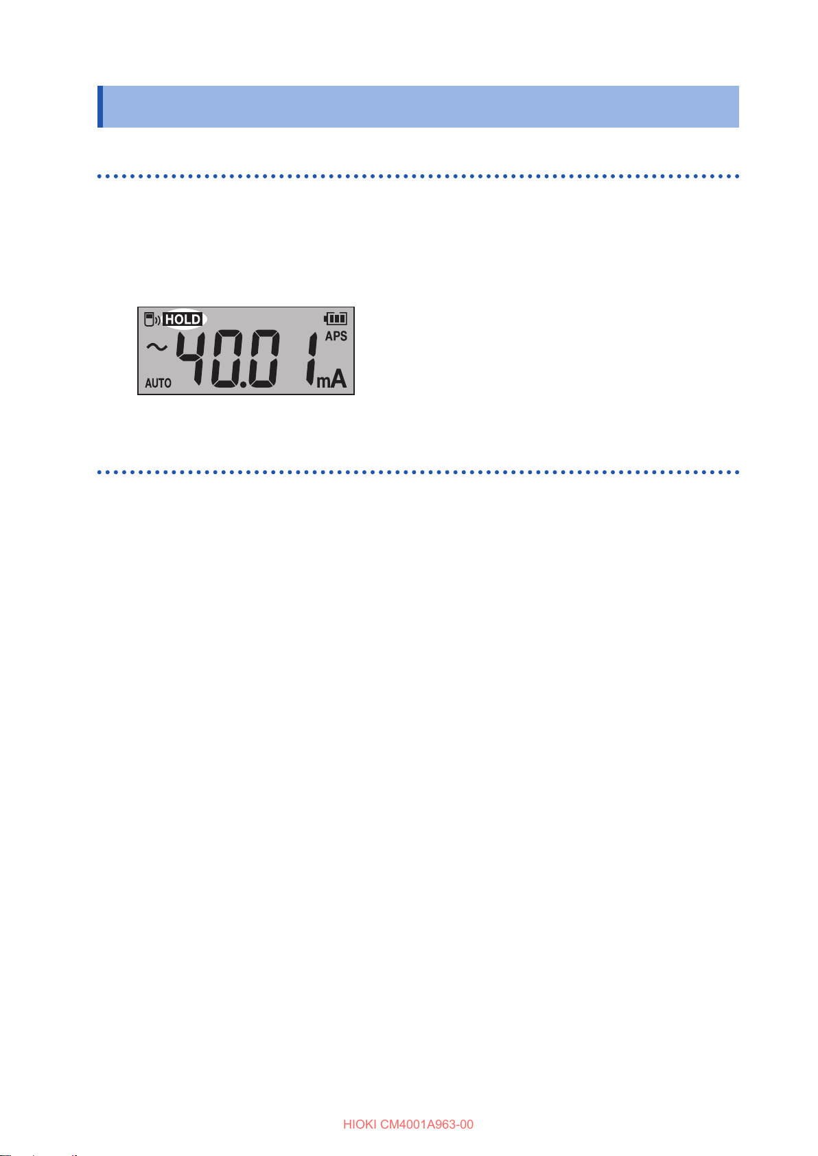
You can stop the display refresh at any time.
Press the HOLD key.
1
The HOLD key lights up, and the [HOLD] symbol appears on the display.
(To cancel, press the HOLD key again.)
Hold Function (HOLD)
Auto hold
When the measured value becomes stable, the display refresh stops automatically.
Hold down the HOLD key for 1 s or more.
1
The HOLD key lights up, and the [HOLD] symbol blinks on the display.
Clamp the instrument around an object to be measured.
2
When the measured value become stable, the display refresh stops automatically.
When performing the next measurement, remove the instrument from the wire and clamp the
instrument around the object under measurement again.
(To cancel, hold down the HOLD key for 1 s or more.)
9

Hold Function (HOLD)
HIOKI CM4001A963-00
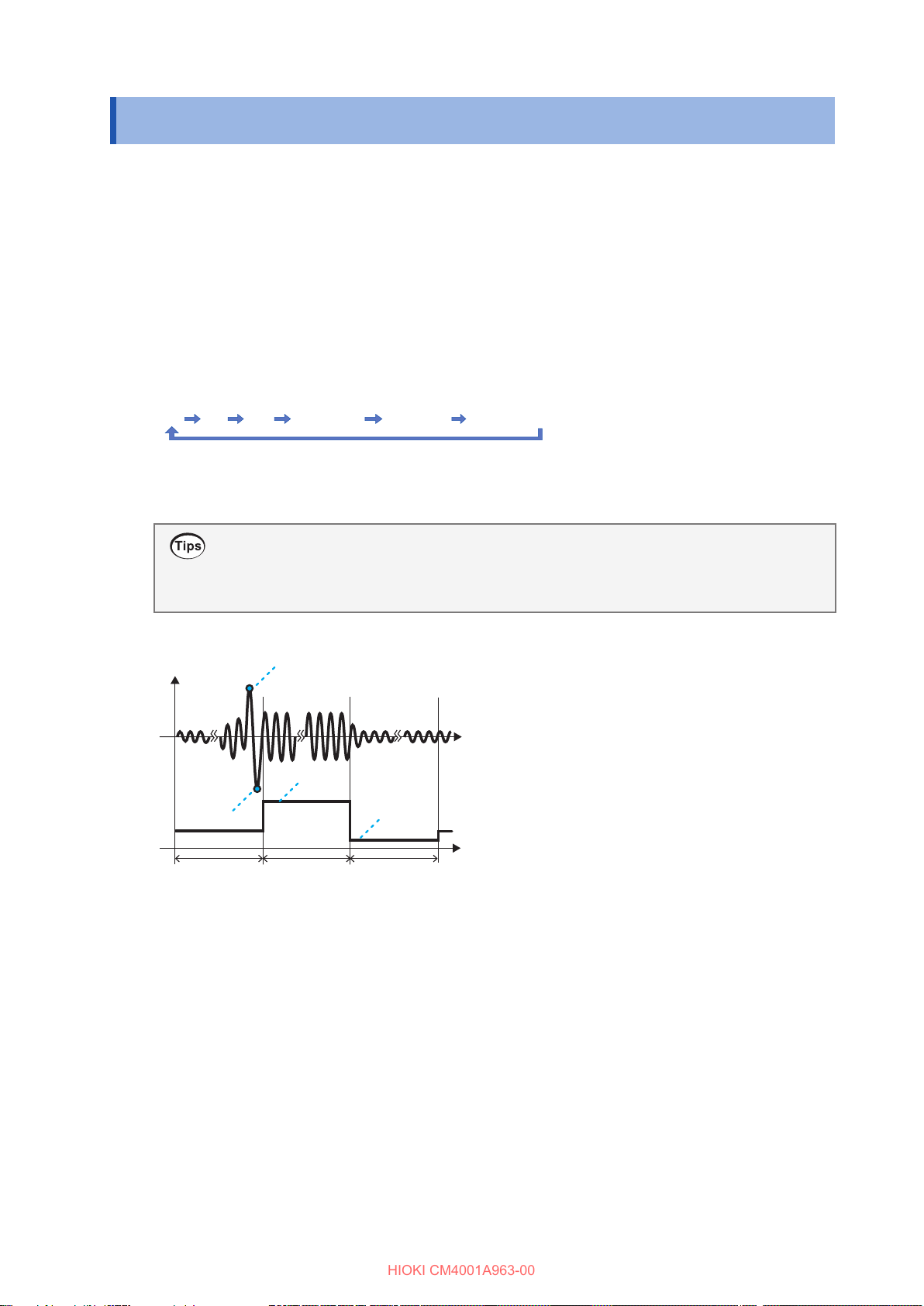
Auto-hold conditions
When both the following conditions are satised, the instrument freezes the readout.
• The measured value does not uctuate beyond the variation range for a certain period.
• The measured value exceeds the threshold value.
The instrument continues to freeze the readout until the auto-hold conditions are satised again.
Auto hold example
50.0 A
: Variation
〇: Held value
Start: Measurement start
(Clamped around target)
Stop: Measurement stop
(Removed from target)
Threshold value
Example: 10.0 A
Time
Stop
Measured
value
Start
Auto hold example
100.0 A
(1) (2)
Stop
Start
Stop
Start
(1) The instrument does not freeze the readout automatically. (The measured value does not
become less than the threshold value.)
(2) The instrument does not freeze the readout automatically. (The measured value does not
exceed the threshold value.)
The variation range and threshold value may vary depending on the range.
Range Variation width Threshold value
60.00 mA
600.0 mA
6.000 A
60.00 A
600.0 A
400 counts or less
150 counts
500 counts or less
10
Max., Min., Average, and Peak Values (MAX, MIN)
MAX
MIN AVG PEAK MAX PEAK MIN
Presently measured value
HIOKI CM4001A963-00
Max., Min., Average, and Peak Values (MAX, MIN)
The instrument can display the maximum, minimum, average, highest peak, or lowest peak values
of the measured data. The auto power save function is disabled.
Clamp the instrument around an object to be measured.
1
Press the RANGE key switch the range.
2
If you switch from the auto range to MAX or MIN mode, the range is xed at the presently set
range.
Press the MAX/MIN key.
3
Every time you press the key, another item is displayed.
(To cancel, hold down the MAX/MIN key for 1 s or more.)
• To freeze the readouts, press the HOLD key.
• The instrument measures the RMS value. AVG means the average value of all
Peak min.
measured values.
Peak max.
Max.
Min.
Waveform
Measured value
(RMS value)
Display refresh interval
11

Inrush Current Measurement (AC INRUSH)
HIOKI CM4001A963-00
Inrush Current Measurement (AC INRUSH)
The instrument can measure AC inrush current.
Press RANGE to set the range.
1
Press and hold the MAX/MIN key and RANGE key simultaneously for 1 s or more to enable
2
inrush current measurement.
For information on the trigger level, see the specications.
The instrument cannot measure inrush current including DC components accurately.
RMS value (inrush)
Example: 60 A
AC
Exapmple: 150 A
AC inrush peak vale
Inrush current occurance period
(several dozen to several hundred milliseconds)
The inrush measurement range is set as follows depending on the range when the current is
measured.
Range when the current is measured Inrush measurement range
Auto 600.0 A range
60.00 mA 600.0 mA range
600.0 mA, 6.000 A, 60.00 A, 600.0 A Range when the current is measured
To cancel, hold down the MAX/MIN and RANGE keys simultaneously for 1 s or more.
12

Comparator Function (COMP)
HIOKI CM4001A963-00
Comparator Function (COMP)
When a measured value exceeds the threshold value, a buzzer sounds and the warning backlight
(p. 16) lights up.
You can also disable the buzzer sound.
The auto range cannot be used when the comparator function is enabled.
Hold down the key for 1 s or more.
1
The comparator function is enabled.
(To cancel, hold down the key for 1 s or more.)
Press the MAX/MIN key or RANGE key to set the threshold value.
2
Holding down the key increases or decreases the value continuously.
Press the HOLD key.
3
The threshold value is conrmed, and the instrument displays the measurement screen.
Video
Find issues faster with a comparator function on YouTube
13

Simple Event Logging Function
HIOKI CM4001A963-00
Simple Event Logging Function
The instrument can update the maximum value display from the start to the stop of recording.
When the maximum value exceeds the set threshold value, the backlight ashes on and o in red
to warn.
Turn the instrument on while holding down the HOLD key and key simultaneously.
1
The HOLD key blinks.
Press the MAX/MIN key () or RANGE key () to select the threshold value.
2
Press the HOLD key.
3
The threshold value is conrmed, and the HOLD key blinks.
Press the MAX/MIN or RANGE key to enable or disable the lter function.
4
Press the HOLD key.
5
The lter setting is conrmed, and the [HOLD] symbol and the [rUn] segments blink on the display.
To change the threshold value
Press the MAX/MIN key or RANGE key to return to the threshold value selection
screen (step
2
).
Press the HOLD key.
6
The instrument starts event logging.
14

Simple Event Logging Function
HIOKI CM4001A963-00
Press the MAX/MIN or RANGE key.
7
The logging stopping conrmation screen appears.
The display returns to the logging screen after approximately four minutes of inactivity.
Press the HOLD key.
8
The instrument stops the event logging. The instrument resets the maximum value and returns the
logging start screen (step
5
)
Event logging in progress
The instrument display the maximum value from the recording start.
The blinking red backlight warns you that the maximum value exceeds the set threshold value.
Press HOLD to freeze the readout.
Finishing the simple event logging
Cycle the instrument.
15
Auto Power Save Function (APS)
HIOKI CM4001A963-00
Auto Power Save Function (APS)
Using the auto power save function can reduce the battery consumption.
When you turn on the instrument, the auto power save function is enabled automatically.
When using the instrument continuously for an extended period of time, turn on the instrument
while holding down the HOLD key to disable the auto power save function.
Backlight
Display backlight
Backlighting the display allows you to see the display clearly even in a dark place.
Pressing the key can turn the display backlight on and o. The backlight automatically is turned
o after about 40 s of inactivity.
To disable the automatic backlight shuto, turn on the instrument while holding down the key.
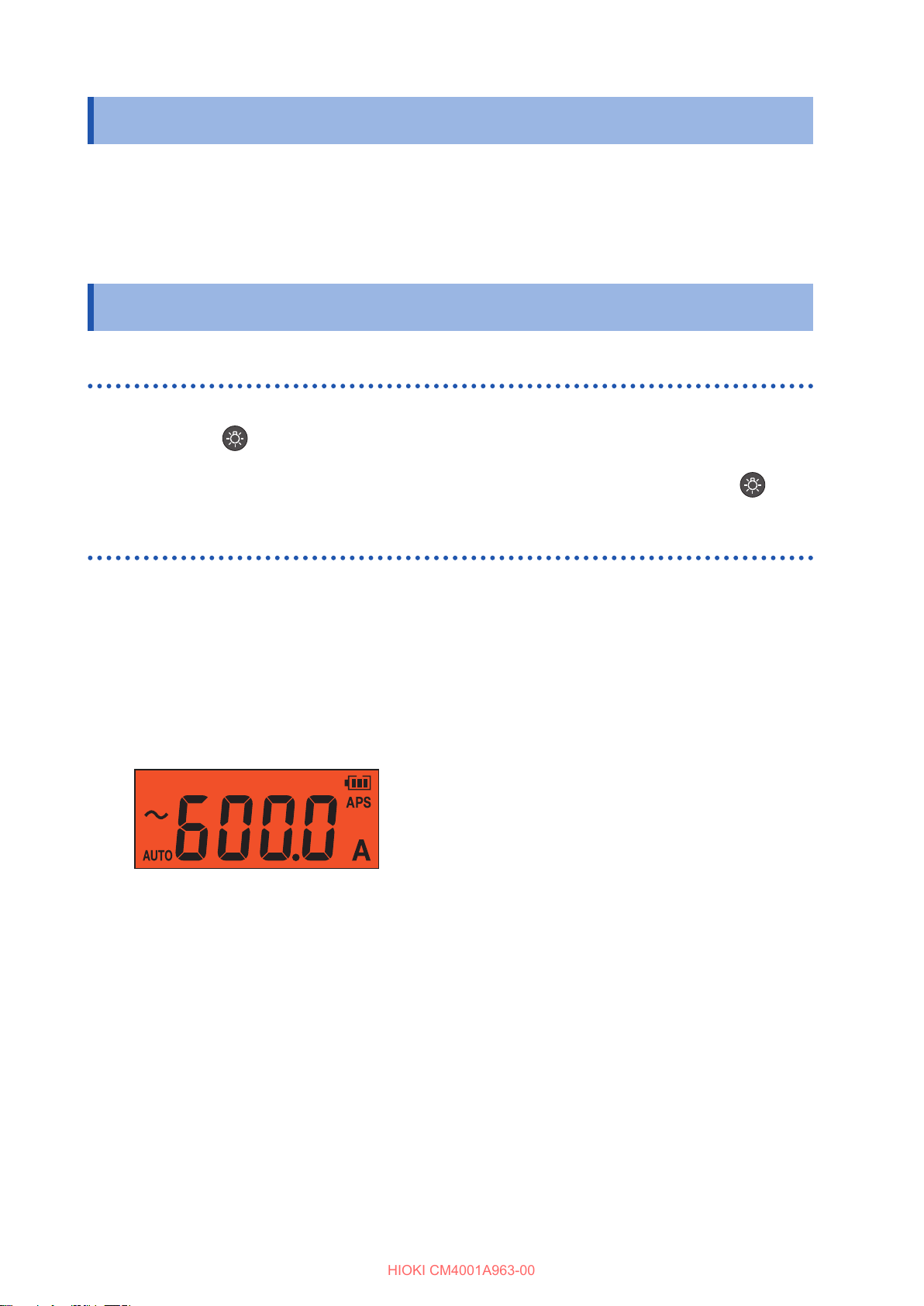
Warning backlight
When any of the following occurs, the backlight lights up or blink in red to warn you.
• Overload(if the measured current value exceeds the measurement range)
The full-scale value blinks and the buzzer sounds. Quit the measurement immediately.
• When the measured current exceeds the measurable range (overrange, with a manual range
used)
The full-scale value blinks. Set the instrument to a proper range.
• If the measured value exceeds the threshold value with the comparator function or event
recording function
The warning backlight works only for the present measured value. The warning backlight does not
work for the freezing value and recorded values of the MAX, MIN, AVG, PEAK MAX, and PEAK
MIN display functions.
16
Wireless Communications Function
HIOKI CM4001A963-00
Wireless Communications Function
When the Z3210 Wireless Adapter (option) is installed, the wireless communications function can
be used. Concurrent use of GENNECT Cross and the HID function (p. 20) is not available.
Using GENNECT Cross
Using GENNECT Cross allows you to check and record the measured data of the instrument and
create measurement reports using your mobile device.
For more information about this functionality, see the Help function in the GENNECT Cross
(application software, free of charge).
GENNECT Cross special site
• The communications range is approximately 10 m (line of sight). The communications range
varies signicantly depending on the presence of obstructions (walls, metallic shielding, etc.) and
the distance between the oor (ground) and the instrument. To ensure the stable communication,
make sure that the radio wave intensity is sucient.
• GENNECT Cross is free, but you may be subject to Internet data fees when downloading and
using the app.
• GENNECT Cross may not work properly on some devices.
• The Z3210 uses the 2.4 GHz band wireless technology. It may not be possible to establish
communications if there is equipment that uses the same frequency band, for example a wireless
network (IEEE 802.11b/g/n), nearby.
When the instrument is placed on the oor or ground, the communication distance
becomes shorter. It is recommended that you move the instrument from the oor or
ground and place it on a desk or table or hold it by hand.
17
Wireless Communications Function
HIOKI CM4001A963-00
Using the wireless communications function
Connect the Z3210 Wireless Adapter (option) to the instrument.
1
Install GENNECT Cross on your mobile device.
2
Turn on the instrument, and then hold down the HOLD and MAX/MIN keys simultaneously
3
for 1 s or more.
The wireless communications function is enabled.
ashes: communicating
appears: wireless function on
disappears: wireless function o
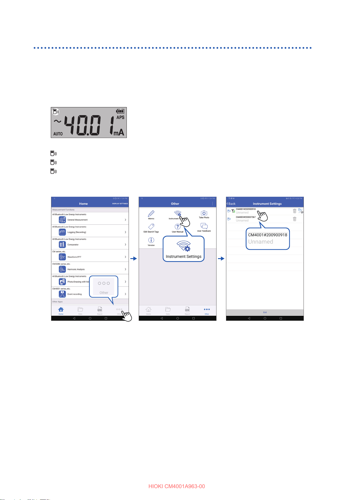
Launch GENNECT Cross and pair it with the instrument.
4
• When GENNECT Cross is started for the rst time (when there is no registered instrument), the
Instrument Settings screen appears.
• When the instrument is placed near your mobile device, its connection is registered automatically
on the Instrument Settings screen of GENNECT Cross (up to eight instruments).
• Wait for 5 to 30 s until the connection of the instrument is registered after turning on the
instrument. If the connection of the instrument is not registered after 1 minute has elapsed, restart
GENNECT Cross and the instrument.
18
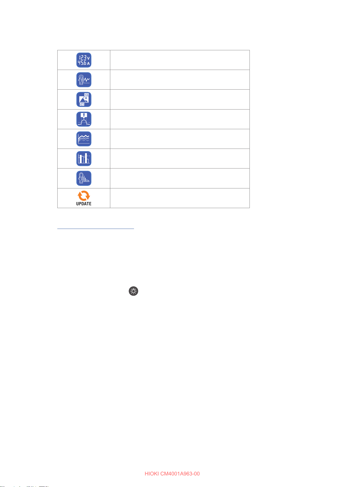
Choose a measurement function to perform measurement.
HIOKI CM4001A963-00
5
General measurement
Waveform graph, FFT
Photo drawing function
Event logging (p. 19)
Logging
Comparator
Harmonic analysis
Wireless Communications Function
Firmware updating of the instrument
For detail information, please visit our website.
GENNECT Cross > Functions
Event Logging Function (EVENT)
The event logging function logs the data when measured values exceed a desired threshold value,
which can be set with GENNECT Cross. For details, see the Help function in GENNECT Cross.
The number of logged events can be checked using the instrument.
Hold down the HOLD and keys simultaneously for 1 s or longer.
1
The number of logged events is displayed.
• The instrument may not measure events with a duration time of less than 200 ms accurately,
failing to detect events.
• The instrument can record up to 99 events. The event recording terminates when the recorded
events reach 99 in number.
• When you start another event logging session, the instrument deletes previously logged data.
19
Wireless Communications Function
HIOKI CM4001A963-00
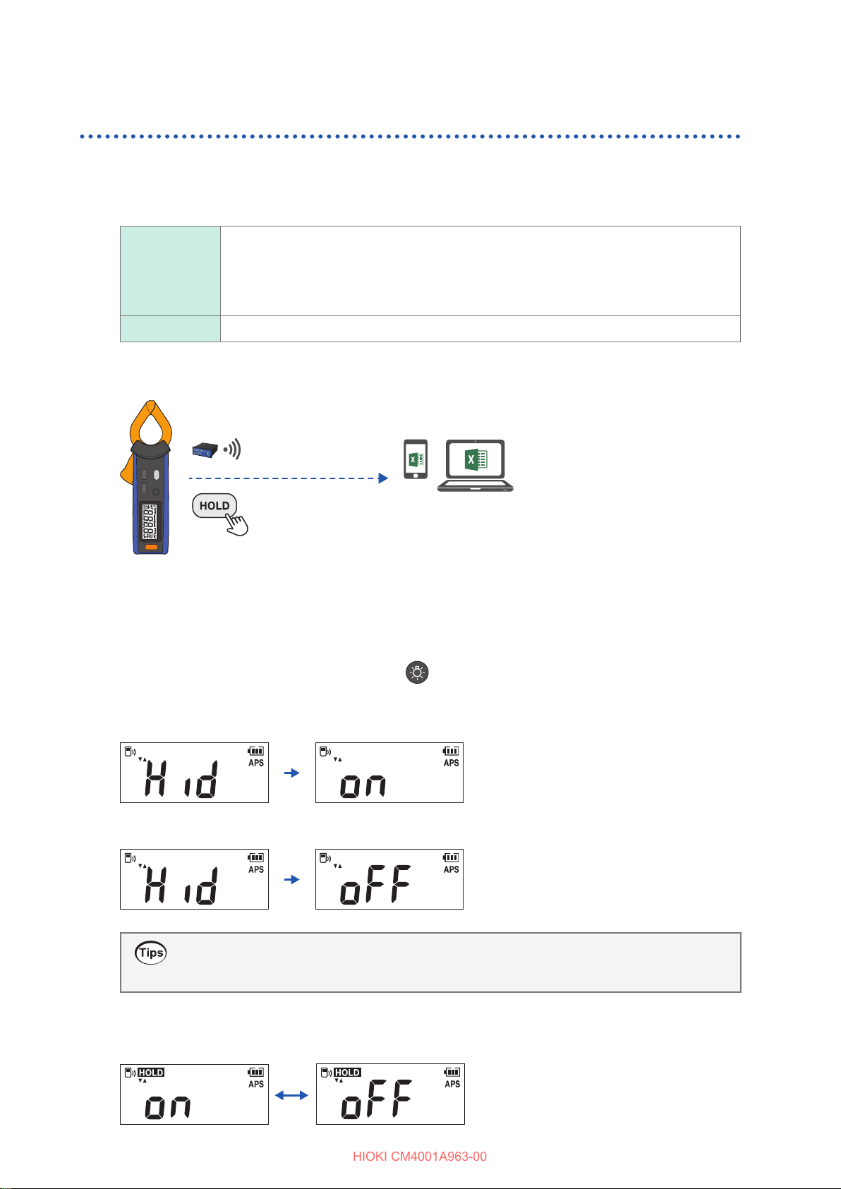
Z3210-to-Excel® direct data entry function (Excel® direct input function, HID function)
Concurrent use of GENNECT Cross (p. 17) and the HID function is not available.
The human interface device (HID) prole, with which the Z3210 Wireless Adapter is equipped, is a
prole same as that wireless keyboards use.
HID ON
HID OFF
The setting whether the HID function has been enabled or disabled is not saved in the instrument
but in the Z3210.
Preparatory to data entry, open an Excel® le on your mobile device or computer
and choose a cell. When the instrument’s display freezes, the measured values
are entered on the cells. The use of this function with the auto hold function
enabled comes in handy. (p. 9)
When you wish to use GENNECT Cross, disable the HID function.
Conrming and toggling the HID setting
Remove the instrument from the object under measurement and turn o the instrument.
1
Connect the Z3210 Wireless Adapter (option) to the instrument.
2
Turn the power on while holding down the and RANGE keys simultaneously.
3
The HID setting saved in the Z3210 is displayed.
When the HID function is enabled
When the HID function is disabled
If you do not wish to change the HID setting, press the power key to turn o the
instrument.
Press the MAX/MIN or RANGE key to enable or disable the HID function.
4
The HOLD key blinks. Every time you press the key, the HID function switches on and o.
20

Wireless Communications Function
HIOKI CM4001A963-00
Press the HOLD key.
5
The HID setting is toggled, and the instrument is automatically turned o.
If the HID function cannot be enabled
Use the rmware updating function of GENNECT Cross (ver. 1.8 or later) to update the Z3210.
IMPORTANT
To switch from the HID function to GENNECT Cross
If you start GENNECT Cross without canceling the paring between the mobile device and the
instrument, GENNECT Cross may not be able to recognize the instrument as a connectible
device. Follow the procedure below to reconnect the instrument to GENNECT Cross.
®
1. Use the Bluetooth
2. Disable the Z3210’s HID function.
3. Use the Instrument Setting of GENNECT Cross to reconnect the instrument.
setting of your mobile device to delete the instrument.
For detail information, please visit the Z3210’s website.
21

HIOKI CM4001A963-00
www.hioki.com/
 Loading...