

Page 1

9754
Instruction Manual
CLAMP ON NOISE SENSOR
May 2015 Revised edition 3
9754A981-03 15-05H
EN
Page 2

Page 3

i
Contents
Contents
Introduction ...............................................................1
Verifying Package Contents......................................1
Safety Information.....................................................2
Operating Precautions..............................................4
Chapter 1 Overview 9
1.1 Product Overview........................................9
1.2 Names and Functions of Parts..................10
Chapter 2 Measurement 11
2.1 Measurement Procedure...........................13
2.2 Disconnecting the NOISE SENSOR .........15
2.3 When Connecting to Instruments other
than the 3145-20 ................................... .. ..16
Chapter 3 Specifications 19
Chapter 4 Maintenance and Service 23
4.1 Cleaning....................................................23
4.2 Troubleshooting.........................................24
1
2
3
4
5
6
7
8
9
10
索引
9754A981-03
Page 4

Contents
ii
Page 5
1
Introduction
Thank you for purchasing the HIOKI "Model 9754 CLAMP ON
NOISE SENSOR." To obtain maximum performance from the
instrument, please read this manual first, and keep it handy for
future reference.
This device is a sensor for use with a 3145-20 NOISE HiLOGGER. Please carefully read the instruction manual included with
the NOISE HiLOGGER and follow all safety precautions.
The 9754 CLAMP ON NOISE SENSOR can also be connected
to other waveform measuring equipment and used to monitor
waveforms and current. Be sure to read and follow all safety
precautions included in the instruction manual of whichever
measuring instrument you use.
Verifying Package Contents
When you receive the instrument, inspect it carefully to ensure
that no damage occurred during shipping. If damage is evident,
or if it fails to operate according to the specifications, contact
your dealer or Hioki representative.
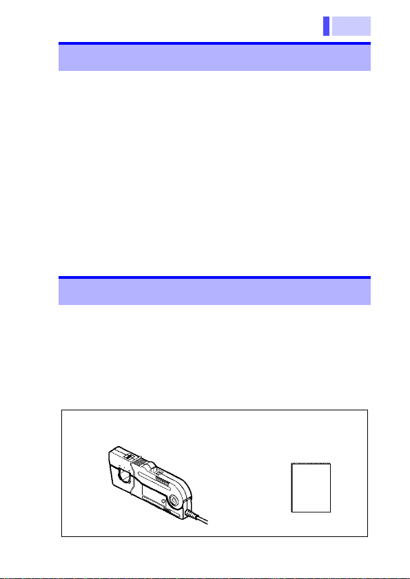
Package Contents
Model 9754 CLAMP ON NOISE
SENSOR..........................1
Instruction Manual
...........................1
1
2
3
4
5
6
7
8
9
10
索引
Page 6
2
Safety Information
This instrument is designed to comply with
IEC 61010 Safety Standards, and has been
thoroughly tested for safety prior to shipment. However, mishandling during use
could result in injury or death, as well as
damage to the instrument. Be certain that
you understand the instructions and precautions in the manual before use. We disclaim
any responsibility for accidents or injuries not
resulting directly from instrument defects.
Safety Symbols
This manual contains information and warnings essential for
safe operation of the instrument and for maintaining it in safe
operating condition. Before using it, be sure to carefully read the
following safety precautions.
In the manual, the symbol indicates particularly
important information that the user should read
before using the instrument.
The symbol printed on the instrument indicates
that the user should refer to a corresponding topic in
the manual (marked with the symbol) before
using the relevant function.
Indicates that only insulated conductors suited to the
voltage of the circuit under test can be measured.
Indicates AC (Alternating Current).
Page 7
3
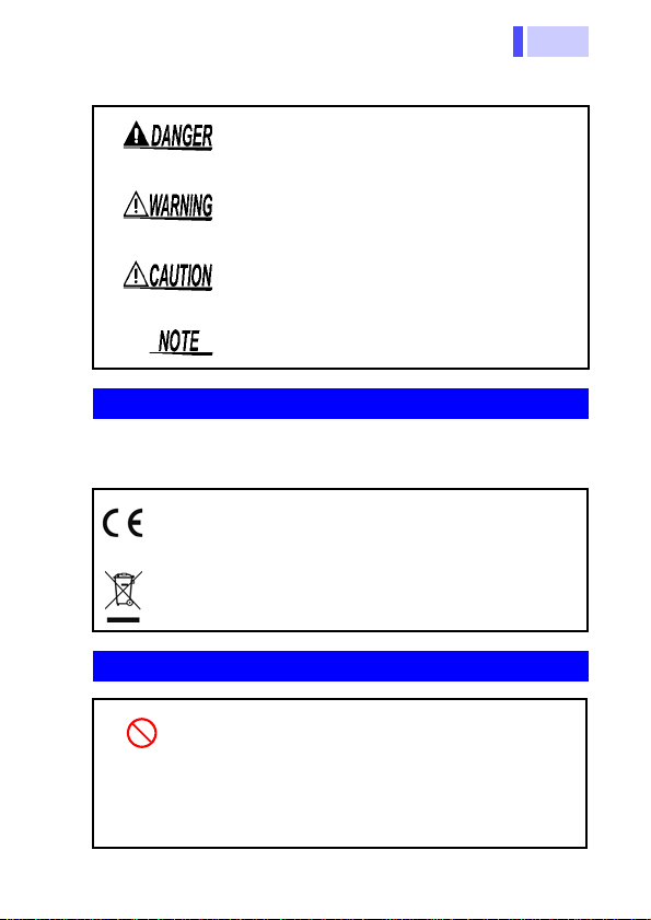
The following symbols in this manual indicate the relative importance of cautions and warnings.
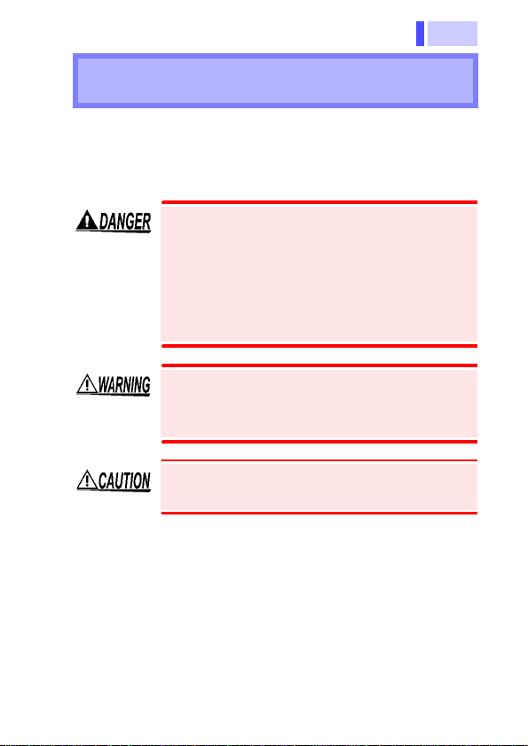
Indicates that incorrect operation presents an
extreme hazard that could result in serious
injury or death to the user.
Indicates that incorrect operation presents a
significant hazard that could result in serious
injury or death to the user.
Indicates that incorrect operation presents a
possibility of injury to the user or damage to
the instrument.
Indicates advisory items related to performance or correct operation of the instrument.
Symbols for various standards
The following symbols in this manual indicate the relative importance of cautions and warnings.
This symbol indicates that the product conforms to
regulations set out by the EC Directive.
Indicates the Waste Electrical and Electronic Equipment Directive (WEEE Directive) in EU member
states.
1
2
3
4
5
6
7
8
9
Other Symbols
Indicates a prohibited action.
(p. ) Indicates the location of reference information.
Indicates that descriptive information is provided
*
below.
10
索引
Page 8
4
Operating Precautions
Preliminary Checks
Before using the instrument the first time, verify that it operates
normally to ensure that the no damage occurred during storage
or shipping. If you find any damage, contact your dealer or Hioki
representative.
Operating Environment
Operating temperature and humidity: 0 to 40
80%RH or less (no condensation)
Accuracy guarantee for temperature and humidity: 23
9F), 80%RH or less (no condensation)
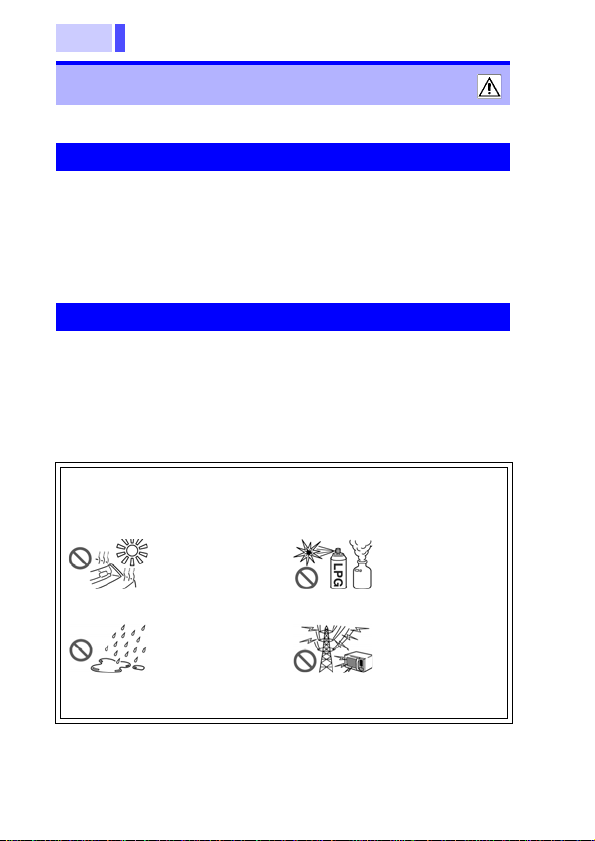
Avoid the following locations that could cause an accident or
damage to the instrument.
Exposed to direct sunlight
Exposed to high
temperature
Exposed to liquids
Exposed to high
humidity or condensation
C (32 to 104F),
5C (73
In the presence
of corrosive or
explosive gases
Exposed to
strong electromagnetic fields
Near electromagnetic radiators
Page 9
5
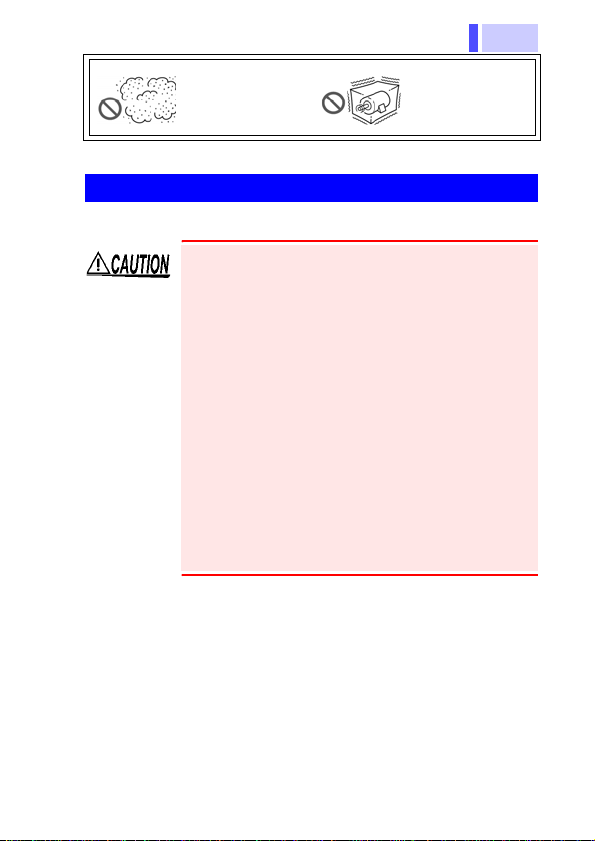
Exposed to high
levels of particulate dust
Subject to vibration
1
Handling the Instrument
• To avoid damage to the instrument, protect it
from physical shock when transporting and handling. Be especially careful to avoid physical
shock from dropping.Be especially careful to
avoid physical shock from dropping.
• Keep the clamp jaws and core slits free from foreign objects, which could interfere with clamping
action.
• Keep the clamp closed when not in use, to avoid
accumulating dust or dirt on the mating core surfaces, which could interfere with clamp performance.
• To avoid breaking the cables, do not bend or pull
them.
2
3
4
5
6
7
8
9
10
索引
Page 10

6
Page 11

7
1.1 Product Overview
Overview Chapter 1
1.1 Product Overview
This device is a current sensor for use with the 3145-20 NOISE
HiLOGGER. By simply clamping onto the conductor to be measured one can easily monitor noise current levels.
It can also be connected to the measuring instruments of other
waveform measuring equipment to monitor waveforms and current levels.
Features
• Easy noise current measurement with a clamp
• Broad frequency bandwidth 1 kHz to 100 MHz (-3 dB)
1
2
3
4
5
6
7
8
9
10
索引
Page 12
1.2 Names and Functions of Parts
8
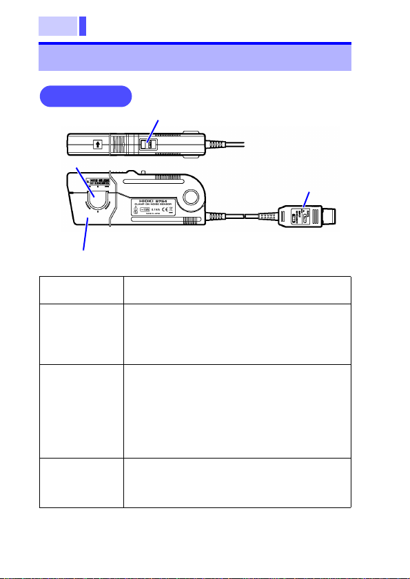
Front Panel
(1) Clamp
(3) Sensor head
(2) Slider
(4) BNC connector
1.2 Names and Functions of Parts
(1) Clamp Clamps around the conductor to be mea-
(2) Slider Used to open and close the clamp. Always
(3) Sensor head This clamps the conductor being measured
(4) BNC
Connector
sured.
use this slider when opening and closing the
clamp. When closing, push the slider all the
way until it clicks shut. This will lock the
clamp and keep it from opening.
and carries out the actual current measurement. It is a precision assembled component, including a molded section and ferrite
core. It may be damaged if subjected to sudden changes in ambient temperature, or
mechanical strain or shock, and therefore
great care should be exercised in handling it.
Outputs the current waveform of the conductor being measured at a constant rate (0.1V/
A). Connect to the input terminal of the 314520 NOISE HiLOGGER.
Page 13
9
1.2 Names and Functions of Parts
Measurement Chapter 2
This device cannot be used with exposed conductors, so please
use it with insulated conductors. Insulation must meet the
requirements of the measurement category, working voltage,
and pollution degree of the circuit being tested.
• To avoid electrical shock, be careful not to
damage the insulation of the conductor
being measured.
• Do not measure around a bare conductor.
Doing so may result in short-circuit or electric shock. Take measurements at a location on an insulated wire where there is
sufficient insulation for the circuit voltage.
To avoid electric shock when measuring live
lines, wear appropriate protective gear, such
as insulated rubber gloves, boots and a
safety helmet.
To avoid damaging the unit, do not apply current
that exceeds the maximum continuous input
range. ( p.17)
* Maximum continuous input range:
This range is based on heat that is internally generated during
sine wave input at a prescribed frequency at room temperature. It varies according to the frequency of the measured
current. (Use the 9754 CLAMP ON NOISE SENSOR at the
highest effective value within the maximum continuous input
range.) In addition to the maximum continuous input range,
there is also the "maximum peak current value 15 Apeak"
product specification. This indicates an upper waveform
response limit of 15 Apeak.
1
2
3
4
5
6
7
8
9
10
索引
Page 14

1.2 Names and Functions of Parts
10
• Acoustic resonance may occur depending on the
level and frequency of the measured current, but
this will not affect measurement unless a foreign
substance such as dust is present on the contact
surfaces of the sensor head.
• If there are high frequency elements included in
the measured current, it will generate high heat.
When taking measurements be cautious of the
sensor heating up.
• The output of this device is terminated internally. When connecting with a waveform measuring instrument, use an instrument with an
input resistance of 1 M or higher. Accurate
measurement cannot be made at 50 input
resistance.
• When monitoring high frequency waveform current elements superimposed on direct current or
commercial frequency current, it is necessary to
pay attention to the following. Attenuation characteristics in the low frequency area are affected
by direct current or commercial frequency current
levels. As the current level increases, magnetic
saturation of the sensor magnetic core causes a
decrease in amplitude and can generate waveform distortion. For example, with a sine wave
input of 15 Apeak, 15 kHz, product specifications
will not be met if the superimposed DC current
exceeds approximately 8 A. Input current levels
must be in accordance with " Derating according
to frequency" ( p.19).
• When clamping together on the round-trip conductors of a commercial circuit, position the two
conductors as close together as possible. The
output value is influenced by the position of the
conductors in the clamp opening. Even if the
round-trip current levels are equal, the clamp
sensor output value may not equal zero. If two
approximately
sured in the round-trip state, and the current
flowing in the conductors is 100 A (55 Hz), the
clamp output value may be approximately 50
mA.
10 mm conductors are mea-
Page 15
11
2.1 Measurement Procedure
Turn until it clicks
Line up
Line up
(1)
(2)
2.1 Measurement Procedure
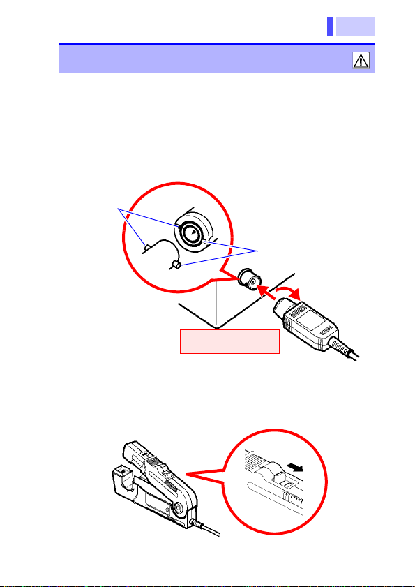
1.
Turn on the power of the instrument being
connected to the 9754 CLAMP ON NOISE
SENSOR.
2. Connect the BNC connector of the 9754 CLAMP
ON NOISE SENSOR to the input terminal of the
instrument being connected to.
3. Measurement settings are made on the instrume nt
being connected to.
Check the settings of the instrument being connected to.
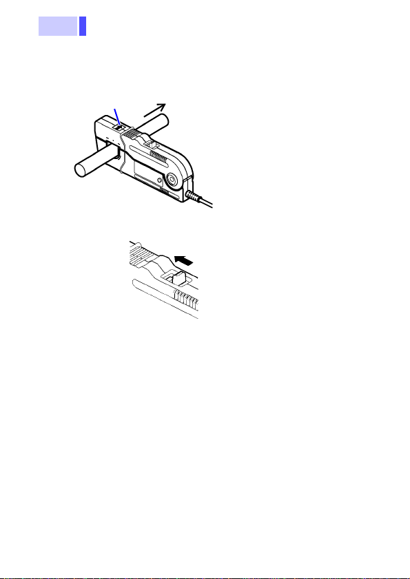
4. Pull the slider on the sensor to open the clamp.
1
2
3
4
5
6
7
8
9
10
索引
Page 16
12
5. Clamp the conductor to be measured and close the
Make sure that the current direction indicator arrow matches the direction
of current flow on the conductor being measured.
Make sure also that the
conductor is clamped in
the center of the clamp
opening.
Current
Current direction
indicator
6. Press on the slider until it clicks to lock shut.
7. Monitor noise current.
2.1 Measurement Procedure
clamp.
Press the sensor slider until the "UNLOCK" message disappears and "LOCK" is displayed, and confirm that the
slider is firmly locked and the clamp securely closed.
The output rate of this device is 0.1 V/A. When using a
general purpose waveform monitoring instrument, derive
the current sensitivity from the voltage sensitivity. For
example, if the waveform measurement instrument's voltage sensitivity is 100 mV/division, the current sensitivity
is 1 A/division.
Page 17
13
2.2 Disconnecting the NOISE SENSOR
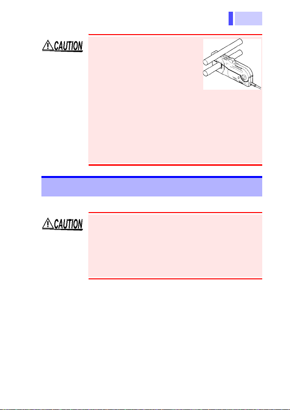
Do not place any unclamped
conductor with an electric current of a frequency of 10 kHz
or more near the sensor head.
Current flowing in the conductor nearby may heat up the
sensor head and cause its
temperature to rise, leading to
damage to the sensor. For example, when one side
of a go-and-return conductor is clamped and the
other side is also placed near the sensor head as
shown in the diagram, even if the electric current is
lower than the consecutive maximum current, electric currents in both sides will heat up the wires and
raise the temperature, thereby causing damage t o
the sensor.
1
2
3
4
5
2.2 Disconnecting the NOISE SENSOR
• To avoid damaging the device, always open the
clamp by using the slider.
• When disconnecting the BNC connector, be
sure to release the lock before pulling off the
connector. Forcibly pulling the connector without
releasing the lock, or pulling on the cable, can
damage the connector.
1.
Pull the sensor slider to open the
clamp.
2. Remove the 9754 CLAMP ON NOISE
SENSOR from the conductor being
measured.
3. Turn off the power on the instrument
being connected to.
6
7
8
9
10
索引
Page 18

2.3 When Connecting to Instruments other than
14
2.3 When Connecting to Instruments other than the 3145-20
The 9754 CLAMP ON NOISE SENSOR can be
connected to waveform measuring equipment
other than the 3145-20 NOISE HiLOGGER and
used to monitor current waveforms. Please carefully read the instruction manual included with
whichever instrument you connect to and follow all
safety precautions.
Page 19
15
2.3 When Connecting to Instruments other than
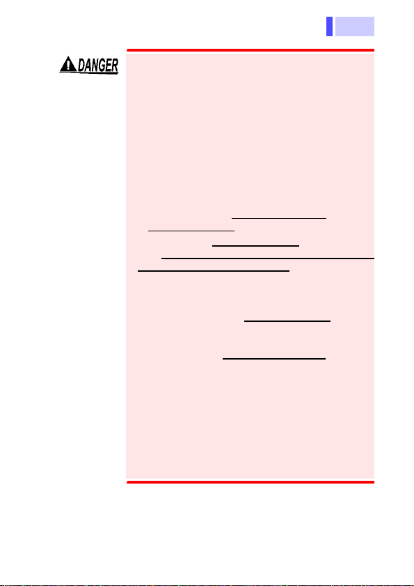
To avoid electrical shock, follow the precautions below to ensure no dangerous voltage
from the power of the instrument being connected to or its other measuring terminals
(those not connected to this device) is
impressed upon the 9754 CLAMP ON
NOISE SENSOR. If dangerous voltage is
impressed upon this device, dangerous voltage will be generated in its BNC connector
and inner circuitry, presenting an extreme
hazard.
• Only connect to instruments which are
constructed with double insulation
a protective earth.
• Confirm that basic insulation which meets
the measurement category, working voltage and pollution degree of the circuit
being tested, is used to isolate the other
measurement terminals of the instrument
being connected to.
If you are not sure basic insulation is used
between the terminals of the measurement
device, do not input voltage which exceeds
the Separated Extra-Low Voltage Earthed
(SELV-E) level into the other terminals of
the instrument.
• Observe all safety precautions of the
instrument you are using.
Refer to the following standards regarding
the meanings of underlined terms.
IEC 61010-1
IEC 61010-031
IEC 61010-2-032
1
2
3
4
and use
5
6
7
8
9
10
索引
Page 20
2.3 When Connecting to Instruments other than
16
<Examples>
• If connecting the 9754 CLAMP ON NOISE SENSOR to a measuring instrument that does not provide isolation between its
input terminals and chassis or other input terminals, co nnect
the ground terminal to a ground potential. If it is connected to a
non-ground potential, voltage will be applied to the ground-side
terminal and chassis, and to the 9754 CLAMP ON NOISE SENSOR, and can cause electrical shock, short circuits, or damage.
• If using BNC-banana plug or other adapters to
connect to input terminals other than BNC connectors, make sure the polarity is correct.
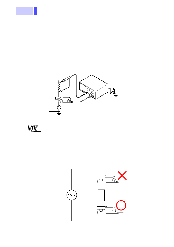
• At high frequencies, common mode noise may
affect measurements taken on the high voltage
side of circuits. As necessary, either limit the frequency range of the waveform measuring instrument, or clamp onto the low-voltage side of the
circuit.
Page 21
17
2.3 When Connecting to Instruments other than
Specifications Chapter 3
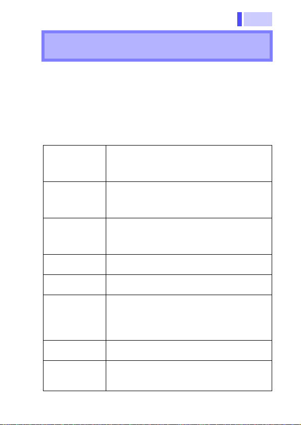
Accuracy
We define measurement tolerances in terms of rdg. (reading)
values, with the following meanings:
rdg. (reading or displayed value)
The value currently being measured and indicated on the measuring instrument.
Accuracy
guarantee for
temperature
and humidity
Bandwidth 1 k to 100 MHz (-3 dB)
Maximum rated
current
Maximum peak
current value
Output voltage
rate
Amplitude
accuracy
Guaranteed
accuracy period
Temperature
coefficient for
sensitivity
5 C (73 9F), 80%RH or less
23
(In the center of the clamp opening)
" Frequency characteristics (typical characteristics)" ( p.19)
AC10 A
" Derating according to frequency" ( p.19)
(Under typical conditions. Varies according to
sine wave input)
15 Apeak
0.1 V/A
3.0%rdg. 0.001% f.s.
(With an f.s. of 10 A)
(Where f = 15 kHz, in the center of the clamp
opening, 1 mA or greater, input is maximum
peak current value or less)
One year
(opening/closing up to 10000 times)
2% (Deviation from normal at 0 to
Within
C or 32 to 104F, f = 15 kHz, 10 A sine
40
wave input)
1
2
3
4
5
6
7
8
9
10
索引
Page 22
2.3 When Connecting to Instruments other than
18
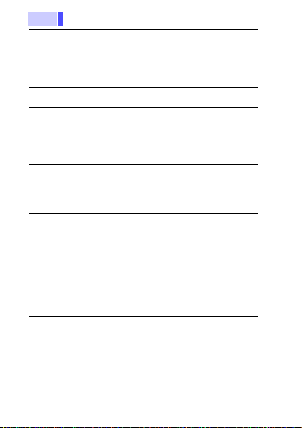
Influence of
conductor
position
Residual current
characteristic
Input
impedance
Operating
temperature
and humidity
Storage
temperature
and humidity
Operating
environment
Diameter of
measurable
conductors
Measurable
conductor
Cable length Sensor cable approx. 2 m (6.56 feet)
Dimensions • Sensor
Mass Approx. 450 g (15.9 oz.)
Applicable
standards
Accessory Instruction Manual
0.4% or less
(Based on f=15 kHz 10 A sine wave input, in
the center of the clamp opening)
40 mA or less
(At f=15 kHz, 10 A, lead wire with 18 mm or
less round-trip distance between lines)
" Input impedance (typical characteristics)"
( p.20)
C (32 to 104F),
0 to 40
80%RH or less (no condensation)
-10 to 50
80%RH or less (no condensation)
Indoor, altitude up to 2000 m (6562 feet)
20 mm (0.79") or less
Insulated conductor
• Termination
Safety
EN61010
EMC
EN61326
C (14 to 122F),
Approx. 176W
2.72"H1.06"D)
(6.93"W
Approx. 27
(0.27"W
55H19D mm
0.11"H0.04"D)
69H27D mm
Page 23
19
2.3 When Connecting to Instruments other than
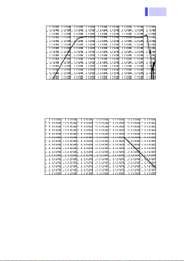
周波数によるディレーティング
0
5
10
15
10 100 1000 10000 100000 100000010000000100000
000
周波数 (Hz)
連続最大入力電流値 (A)
周波数特性(特性例)
-60
-50
-40
-30
-20
-10
1 100 10000 1000000 100000000
周波数 (Hz)
出力 (0dB=1V)
Frequency characteristics (typical characteristics)
10k
1M
100M
Frequency (Hz)
Frequency (Hz)
Output (0dB=1V)
Continuous maximum input current value (A)
10
100
1k
10k
100k
1M
10M
100M
Derating according to frequency
1
2
3
4
5
6
7
8
9
10
索引
Page 24
20
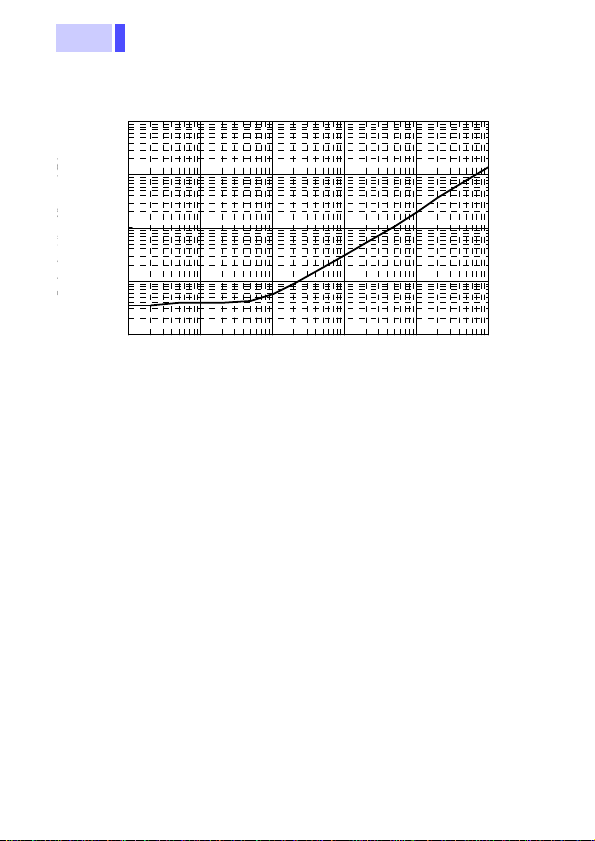
入力インピーダンス(特性例)
0.001
0.010
0.100
1.000
10.000
1000 10000 100000 1000000 10000000 10000000
周波数 (Hz)
入力インピーダンス (Ω)
Input impedance (typical characteristics)
1k
10k
100k
1M
Input impedance ()
Frequency (Hz)
10
1
0.1
0.01
0.001
10M
100M
2.3 When Connecting to Instruments other than
Page 25
21
Maintenance and
Service
4.1 Cleaning
Chapter 4
1
Never modify the instrument. Only Hioki service
engineers should disassemble or repair the instrument. Failure to observe these precautions may
result in fire, electric shock, or injury.
4.1 Cleaning
To clean the instrument, wipe it gently with a soft cloth moistened with water or mild detergent. Never use solvents such as
benzene, alcohol, acetone, ether, ketones, thinners or gasoline,
as they can deform and discolor the case.
Measurements are degraded by dirt on the mating
surfaces of the clamp-on sensor, so keep the surfaces clean by gently wiping with a soft cloth.
2
3
4
5
6
7
8
9
10
索引
Page 26
4.2 Troubleshooting
22
4.2 Troubleshooting
If the instrument seems to be malfunctioning, confirm that the
cables are not open circuited before contacting your dealer or
Hioki representative.
Pack the instrument so that it will not sustain damage during shipping, and include a description of
existing damage. We cannot accept responsibility
for damage incurred during shipping.
Page 27
Page 28

Page 29

Page 30

 Loading...