


BT3563A
HIOKI BT3562A981-11
BT3562A
BT3561A
Instruction Manual
BT3563
BT3563-01
BT3562
BT3562-01
BATTERY HiTESTER
When using the instrument for the
rst time
Names and Functions of Parts
Measurement Preparations
Dec. 2021 Revised edition 11
BT3562A981-11 21
Read carefully before use.
Keep for future reference.
p.11
p.19
-12H
Troubleshooting
Maintenance and Service
Error Display
p.189
p.191
EN
*60034236B*

HIOKI BT3562A981-11

Contents
Introduction.................................................................................1
HIOKI BT3562A981-11
Verifying Package Contents .......................................................2
Safety Information ......................................................................3
Operating Precautions................................................................5
Chapter 1
Overview ___________________________________ 9
1.1 Product Overview ................................................................9
1.2 Features ............................................................................10
i
Contents
4
1.3 Names and Functions of Parts ..........................................11
1.4 Menu Display Sequence (SHIFT
1.5 Measurement Flowchart ...................................................17
→ ENTER) .....................16
Chapter 2
Measurement Preparations___________________ 19
2.1 Preparation Flowchart .......................................................19
2.2 Connecting the Power Cord.............................................. 20
2.3 Connecting the Optional Test Leads.................................. 21
2.4 Turning the Power On and Off ..........................................22
2.5 Selecting the Line Frequency ...........................................24
Chapter 3
Measurement ______________________________ 25
3.1 Pre-Operation Inspection ..................................................25
3.2 Basic Measurement Example ...........................................26
Preparations ........................................................................26
Instrument Settings .............................................................27
Zero-Adjustment ..................................................................28
Measurement ......................................................................29
3.3 Selecting Measurement Mode ..........................................30
3.4 Setting Measurement Range ............................................31
Resistance measurement range .........................................31
Voltage measurement range ...............................................32
Auto-Ranging ......................................................................33
5
6
7
8
9
10
10
11
12
BT3562A981-11
3.5 Setting Sampling Rate ......................................................34
3.6 Zero-Adjust Function .........................................................35
Wiring Method for Zero-Adjustment ....................................35
Executing Zero-Adjustment .................................................35
3.7 Displaying Measurement Results .....................................38
Appendix
Index

ii
HIOKI BT3562A981-11
Contents
Measurement Fault Detection ............................................ 39
Overflow Display ................................................................. 40
Chapter 4
Applied Measurement _______________________41
4.1 Comparator Function ........................................................ 42
Comparator Setting Example 1
(Upper and Lower Threshold Judgment) ........................... 43
Comparator Setting Example 2
(Reference Value and Tolerance Judgment) ..................... 47
Comparator Judgment Beeper Setting ............................... 52
Comparator Execution Mode Setting .................................. 52
Comparator Threshold Method Selection ........................... 53
Upper and Lower Thresholds Setting
(by Reference Value and Tolerance) .................................. 54
Configuring the Absolute Value Judgment Function
(Voltage) .............................................................................55
Enabling and Disabling the Comparator Function .............. 56
Comparator Judgment Results ........................................... 57
Switching Between Measurement Value and Comparator
Setting Displays .................................................................. 58
4.2 Trigger Function ................................................................ 59
Trigger Source Settings ...................................................... 59
Trigger Delay Settings ........................................................ 60
4.3 Measurement Current Pulse Output Function .................. 61
4.4 Averaging Function ........................................................... 63
4.5 Statistical Calculation Functions ....................................... 64
4.6 Memory Function .............................................................. 68
4.7 Key-Lock Function ............................................................ 70
4.8 Panel Save Function ......................................................... 71
4.9 Panel Load Function ......................................................... 72
4.10 Self-Calibration ................................................................. 73
4.11 Measurement Value Output Function ............................... 74
4.12 Key Beeper Setting ........................................................... 75
4.13 Reset Function .................................................................. 76
Chapter 5
External Control (EXT I/O) ____________________ 79
5.1 Overview............................................................................ 79
5.2 Signal Descriptions ........................................................... 80
Pinout .................................................................................80
Input Signals ....................................................................... 81
Output Signals ....................................................................82
ERR Output ........................................................................ 83
Instrument Settings ............................................................. 84

5.3 Timing Chart .....................................................................85
HIOKI BT3562A981-11
5.4 Internal Circuitry ................................................................87
5.5 External Control Q&A ........................................................ 90
Chapter 6
Printing ___________________________________ 91
6.1 Connecting the Printer ...................................................... 91
Connecting the PRINTER to the Instrument .......................92
6.2 Selecting the Interface ......................................................93
6.3 Printing ..............................................................................94
Chapter 7
Analog Output _____________________________ 97
7.1 Connecting Analog Output ................................................97
iii
Contents
7.2 Analog Output Specifications ............................................98
Chapter 8
RS-232C/GP-IB/LAN Interfaces________________ 99
8.1 Overview and Features .....................................................99
8.2 Specifications ..................................................................100
RS-232C Specifications ....................................................100
LAN Specifications ............................................................100
GP-IB Specifications .........................................................101
8.3 Selecting the Connections and Protocol ........................102
Attaching the Connector ....................................................102
Selecting the Interface ......................................................105
Setting LAN communications ............................................106
8.4 Communication Methods ................................................ 108
Message Format ...............................................................108
Output Queue and Input Buffer .........................................112
Status Byte Register .........................................................113
Event Registers .................................................................115
Initialization Items ..............................................................118
Local Function ...................................................................118
8.5 Message List ...................................................................119
Standard Commands ........................................................119
Device-Specific Commands ..............................................121
8.6 Message Reference ........................................................126
Standard Commands ........................................................127
Device-Specific Commands ..............................................131
Measurement Value Formats ............................................159
Command Compatibility
with the Model 3560 AC mΩ HiTESTER ...........................160
8.7 Basic Data Importing Methods ........................................165

iv
HIOKI BT3562A981-11
Contents
8.8 Sample Programs ........................................................... 166
To be prepared in Visual Basic
To be prepared in Visual Basic
Creation Procedure(Visual Basic
Sample Programs(Visual Basic
®
5.0/6.0 ........................... 166
®
2005 .............................. 176
®
2005) ......................... 176
®
2005) ............................ 178
Chapter 9
Specifications _____________________________ 181
9.1 Basic Specifications ........................................................ 181
9.2 Accuracy ......................................................................... 186
9.3 General Specifications .................................................... 188
Chapter 10
Maintenance and Service ___________________189
10.1 Troubleshooting .............................................................. 189
10.2 Cleaning .......................................................................... 191
10.3 Error Display ................................................................... 191
Chapter 11
License Information ________________________ 193
Appendix ________________________________ A 1
Appendix 1 Precautions for Making Custom Test Leads ...............A 1
Appendix 2 AC Four-terminal Method ............................................A 4
Appendix 3 Measurement values when using four-terminal
measurement (Differences in measurement values
due to measurement leads used)................................A 5
Appendix 4 Synchronous Detection System ..................................A 6
Appendix 5 Configuration and Extension of the Test Leads ..........A 7
Appendix 6 Effect of Eddy Currents ...............................................A 8
Appendix 7 Calibration Procedure..................................................A 9
Appendix 8 Zero Adjustment ........................................................A 10
Appendix 9 Test Lead Options .....................................................A 15
Appendix 10Rack Mounting ..........................................................A 17
Appendix 11Dimensional Diagram................................................A 19
Index ________________________________ Index i

1
HIOKI BT3562A981-11
Introduction
Introduction
Thank you for purchasing the HIOKI “Model BT3561A, BT3562A, BT3562, BT3562-01, BT3563A,
BT3563, and BT3563-01 BATTERY HiTESTER. ” To obtain maximum performance from the instrument, please read this manual first, and keep it handy for future reference.
Please review the separate “Operating Precautions” before using the instrument.
This manual uses the following conventions:
The Model BT3561A, BT3562A, BT3562, BT3562-01, BT3563A, BT3563, and BT3563-01 are referred to as
"the instrument."
Unless otherwise noted, the Model BT3562, BT3562-01, and BT3562A are referred to collectively as "Model
BT3562," while the Model BT3563, BT3563-01, and BT3563A are referred to collectively as "Model BT3563."
Latest edition of instruction manual
The contents of this manual are subject to change, for example as a result of product improvements or changes to specifications.
The latest edition can be downloaded from Hioki’s website.
https://www.hioki.com/global/support/download
Trademarks
Microsoft, Windows, Visual Studio, Visual Basic, Edge, and Visual C# are either registered trademarks or
trademarks of Microsoft Corporation in the United States and other countries.

2
Confirm that these contents are provided. (One each)
Model BT3561A BATTERY HiTESTER
Model BT3562 BATTERY HiTESTER
Model BT3562-01 (GP-IB version) BATTERY HiTESTER
Model BT3562A (LAN version) BATTERY HiTESTER
Model BT3563 BATTERY HiTESTER
Model BT3563-01 (GP-IB version) BATTERY HiTESTER
Model BT3563A (LAN version) BATTERY HiTESTER
Instruction Manual
Power Cord
Operating Precautions (0990A903)
HIOKI BT3562A981-11
Verifying Package Contents
Verifying Package Contents
When you receive the instrument, inspect it carefully to ensure that no damage occurred during
shipping. In particular, check the accessories, panel switches, and connectors. If damage is evident,
or if it fails to operate according to the specifications, contact your dealer or Hioki representative.
Use the original packing materials when transporting the instrument, if possible.
Options The following options are available for the instrument. Contact your authorized
Hioki distributor or reseller when ordering.
The options are subject to change. Visit our website for updated information.
Model L2107 CLIP TYPE LEAD (60 VDC or less)
Model 9453 FOUR TERMINAL LEAD (60 VDC or less)
Model 9467 LARGE CLIP TYPE LEAD (50 VDC or less)
Model 9770 PIN TYPE LEAD (60 VDC or less)
Model 9771 PIN TYPE LEAD (60 VDC or less)
Model L2100 PIN TYPE LEAD (1000 VDC or less)
Model L2110 PIN TYPE LEAD (1000 VDC or less)
Model Z5038 0 ADJ BOARD (for model L2100 and L2110)
Model 9637 RS-232C CABLE (9-pin to 9-pin/cross cable)
Model 9151-02 GP-IB CONNECTOR CABLE (2 m)
Model 9642 LAN CABLE

Safety Information
HIOKI BT3562A981-11
This instrument is designed to comply with IEC 61010 Safety Standards, and
has been thoroughly tested for safety prior to shipment. However, mishandling
during use could result in injury or death, as well as damage to the instrument.
Be certain that you understand the instructions and precautions in the manual
before use. We disclaim any responsibility for accidents or injuries not resulting
directly from instrument defects.
This manual contains information and warnings essential for safe operation of
the instrument and for maintaining it in safe operating condition. Before using it,
be sure to carefully read the following safety precautions.
3
Safety Information
In the manual, the symbol indicates particularly important information
that the user should read before using the instrument.
The symbol printed on the instrument indicates that the user should
refer to a corresponding topic in the manual (marked with the symbol)
before using the relevant function.
The following symbols in this manual indicate the relative importance of cautions
and warnings.
Symbols for Various Standards
Other Symbols
Indicates a grounding terminal.
Indicates DC (Direct Current).
Indicates the ON side of the power switch.
Indicates the OFF side of the power switch.
Indicates that incorrect operation presents an extreme hazard that
could result in serious injury or death to the user.
Indicates that incorrect operation presents a significant hazard that
could result in serious injury or death to the user.
Indicates that incorrect operation presents a possibility of injury to
the user or damage to the instrument.
Indicates advisory items related to performance or correct operation of the instrument.
This symbol indicates that the product conforms to regulations set out by
the EU Directive.
Indicates a prohibited action.
(p. )
*
Indicates the location of reference information.
Indicates quick references for operation and remedies for troubleshooting.
Indicates that descriptive information is provided below.
4
HIOKI BT3562A981-11
Safety Information
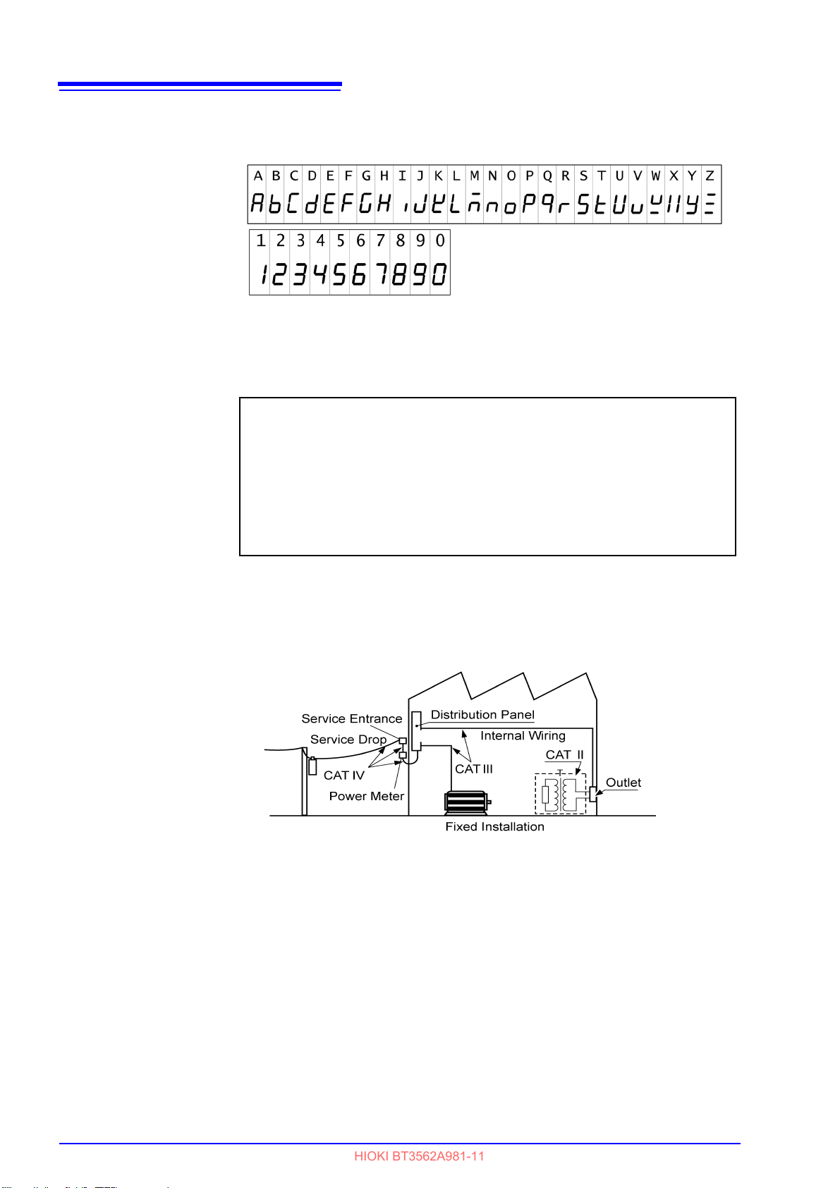
Screen display
The screen of this instrument displays characters in the following manner.
Measurement categories
To ensure safe operation of measurement instruments, IEC 61010 establishes
safety standards for various electrical environments, categorized as CAT II to
CAT IV, and called measurement categories.
CAT II
CAT III
CAT IV
Primary electrical circuits in equipment connected to an AC electrical outlet
by a power cord (portable tools, household appliances, etc.)
CAT II covers directly measuring electrical outlet receptacles.
Primary electrical circuits of heavy equipment (fixed installations) connected directly to the distribution panel, and feeders from the distribution panel
to outlets.
The circuit from the service drop to the service entrance, and to the power
meter and primary overcurrent protection device (distribution panel).
Accuracy
Using a measurement instrument in an environment designated with a highernumbered category than that for which the instrument is rated could result in a
severe accident, and must be carefully avoided.
Use of a measurement instrument that is not CAT-rated in CAT II to CAT IV
measurement applications could result in a severe accident, and must be carefully avoided.
Hioki expresses accuracy as error limit values specified in terms of
percentages relative to reading and full scale, and digits.
Full scale
Reading
Digits
(Maximum displayable value)
Refers to the maximum displayable value of each measurement range.
The instrument has measurement ranges whose values are equal to the maximum displayable values. The limit values of full-scale errors are expressed in
percent of full scale (% of full scale, % f.s.).
(Displayed value)
Refers to the displayed value of the measuring instrument.
The limit values of reading errors are expressed in percent of reading (% of
reading, % rdg).
(Resolution)
Refers to the smallest change in the indication on the digital measuring instrument, i.e., the numeral one in the rightmost place. The limit values of digit
errors are expressed in terms of digits (dgt).

Operating Precautions
Instrument Installation and Operating Environment
The instrument can be used with the stand. (p.15)
It can also be rack-mounted. Appendix (p. A17)
50 mm or more
10 mm or more
Rear
50 mm or more
HIOKI BT3562A981-11
Follow these precautions to ensure safe operation and to obtain the full benefits
of the various functions.
Use of the instrument should confirm not only to itsspecifications, but also to the
specifications of all accessories, options, and other equipment in use.
Operating temperature and humidity:
0 to 40°C (32 ± 104°F), 80%RH or less (non-condensating)
Temperature and humidity range for guaranteed accuracy:
23 ± 5°C (73 ± 9°F), 80% RH or less (non-condensating)
Avoid the following locations that could cause an accident or damage to the
instrument.
Exposed to direct sunlight
Exposed to high temperature
5
Operating Precautions
In the presence of corrosive or explosive gases
To avoid electric shock, do not remove the instrument's case. The internal components of the instrument carry high voltages and may become very hot during
operation.
Avoid using near electrically noisy devices, as the noise may impinge upon the
test object and cause unreliable measurements.
Installation Precautions
• The instrument should be operated only with the bottom downwards.
• Do not place the instrument on an unstable or slanted surface.
Exposed to water, oil,
other chemicals, or
solvents
Exposed to high humidity or condensation
Exposed to high levels of particulate dust
Exposed to strong electromagnetic fields
Near electromagnetic
radiators
Subject to vibration
6
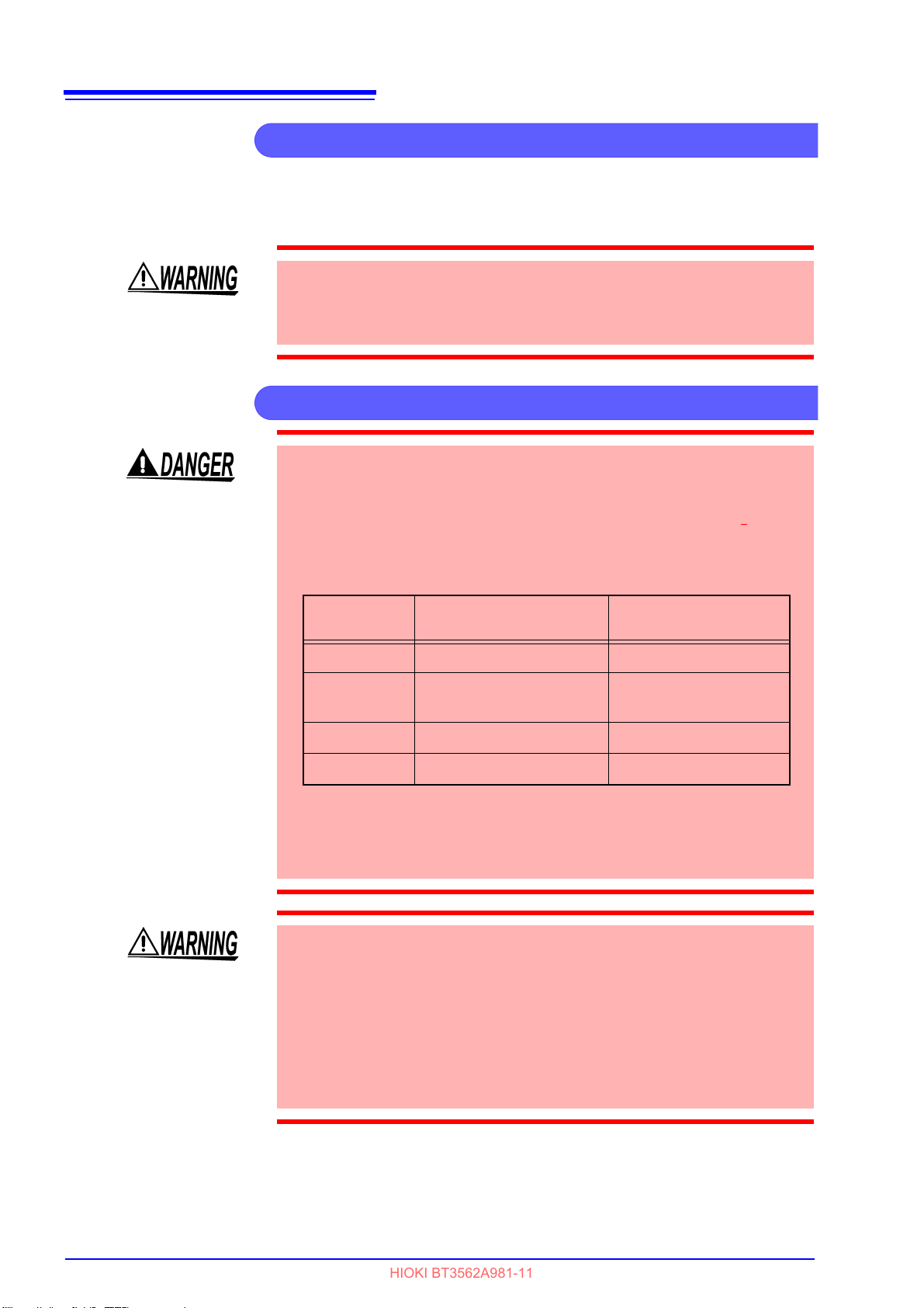
Preliminary Checks
Measurement Precautions
See:"9.1 Basic Specifications" (p.181)
Model Maximum input voltage
Maximum rated voltage
to earth
BT3561A
±
60 V DC
±
60 V DC
BT3562
BT3562-02
±
60 V DC
±
70 V DC
BT3562A
±
100 V DC
±
100 V DC
BT3563
±
300 V DC
±
300 V DC
HIOKI BT3562A981-11
Operating Precautions
Before using the instrument the first time, verify that it operates normally to
ensure that the no damage occurred during storage or shipping. If you find any
damage, contact your dealer or Hioki representative.
Before using the instrument, make sure that the insulation on the power cord
and test leads is undamaged and that no bare conductors are improperly
exposed. Using the instrument in such conditions could cause an electric
shock, so contact your dealer or Hioki representative for replacements.
• To avoid electrical shock, be careful to avoid shorting live lines with the test
leads.
• Do not use the instrument to measure circuits that exceed its ratings or specifications. Damage to the instrument or overheating can cause
shock.
• The maximum input voltage and maximum rated voltage are shown in the
following table.
anelectric
• Never connect a battery cell or module to a motor or other load while it is
being measured. Doing so may result in a surge voltage, which may damage
the instrument or cause injury.
• To prevent electrical shock, verify the ratings of the measurement leads
before measurement and exercise care not to measure voltages that exceed
those ratings.
• Do not touch the metallic tip of probes after measuring high-voltage batteries. Doing so may result in electrical shock since internal instrument components could retain a charge under those conditions. (Internal discharge time:
Approx. 20 sec.)
• To avoid short-circuit accidents, connect the probe's banana terminals to the
instrument before connecting the probes to the battery.
7
Before Connecting and Powering On
Handling the Instrument
HIOKI BT3562A981-11
Operating Precautions
• Use only the specified test leads and cables. Using a non-specified cable may
result in incorrect measurements due to poor connection or other reasons.
• To ensure certified measurement accuracy, allow at least 30 minutes warmup. After warm-up, be sure to execute self-calibration.
See "4.10 Self-Calibration" (p.73).
• The input circuitry includes a protective fuse. Measurement is not possible
when the fuse is blown.
• This instrument internally stores (backs up) all settings (except memory function and measurement values), such as measurement range, comparator
settings and etc., but only when no operation is performed for a certain time.
Therefore, to preserve settings, do not turn the power off for a short time
(about five seconds) after changing a setting. However, measurement settings made through the RS-232C, LAN, or GP-IB interface and measurement
settings loaded by LOAD
rized.
• Select an appropriate measurement range when measuring batteries. Using
a low range such as 3 mΩ to measure a button cell or other battery that has
high internal resistance may result in an open-terminal voltage (approx. 4
V), causing the battery to be charged.
signals of the EXT I/O connector are not memo-
• Before turning the instrument on, make sure the supply voltage matches that
indicated on the its power connector. Connection to an improper supply voltage may damage the instrument and present an electrical hazard.
• To avoid electrical accidents and to maintain the safety specifications of this
instrument, connect the power cord provided only to a 3-contact (two-conductor + ground) outlet.
To suppress noise, the instrument needs to be set to match the frequency of
the power source. Before operating, set the instrument to the frequency of your
commercial power. If the supply frequency is not set properly, measurements
will be unstable.
See "2.5 Selecting the Line Frequency" (p.24).
Make sure the power is turned off before connecting or disconnecting the
power cord.
• To avoid damage to the instrument, protect it from physical shock when
transporting and handling. Be especially careful to avoid physical shock from
dropping.
• Do not apply heavy downward pressure with the stand extended. The stand
could be damaged.
This instrument may cause interference if used in residential areas. Such use
must be avoided unless the user takes special measures to reduce electromagnetic emissions to prevent interference to the reception of radio and television broadcasts.

8
Handling the Test Leads and Cables
HIOKI BT3562A981-11
Operating Precautions
• To avoid breaking the test leads and cables, do not bend or pull them.
• Avoid stepping on or pinching cables, which could damage the cable insulation.
• To avoid equipment failure, do not disconnect the communications cable
while communications are in progress.
• Use a common ground for both the instrument and the computer. Using different ground circuits will result in a potential difference between the instrument's ground and the computer's ground. If the communications cable is
connected while such a potential difference exists, it may result in equipment
malfunction or failure.
• Before connecting or disconnecting any the communications cable, always
turn off the instrument and the computer. Failure to do so could result in
equipment malfunction or damage.
• After connecting the communications cable, tighten the screws on the connector securely. Failure to secure the connector could result in equipment
malfunction or damage.

9
HIOKI BT3562A981-11
1.1 Product Overview
1
Overview Chapter 1
1.1 Product Overview
The Model BT3561A, BT3562 and BT3563 Battery Hitester measure battery
internal resistance using a four-terminal, 1-kHz AC method, while simultaneously
measuring DC voltage (electromotive force [emf]). The high-precision, fast measurement performance and extensive interface capabilities make these models
ideal for incorporating into battery testing production lines.
Chapter 1 Overview

10
HIOKI BT3562A981-11
1.2 Features
1.2 Features
Simultaneously Measures Battery Internal Resistance and Voltage
The four-terminal AC method measures resistance and DC voltage simultaneously, so battery internal resistance and emf are measured and judged at once.
High-Precision Measurements
Resistance measurement resolution of 1 μΩ or 0.1 μΩ and voltage measurement resolution of 10 μV. The voltage measurement accuracy of ±0.01% of
reading is achieved.
High-Speed Measurements
Simultaneous resistance and voltage measurements can be performed as fast
as once every 20 ms.
(Response time of approx. 10 ms + sampling time of approx. 8 ms)
High-voltage measurement
The Model BT3563 supports measurement of high-voltage batteries of up to 300 V.
(the Model BT3561A, BT3562, and BT3562-01 supports measurement of up to
60 V) (the Model BT3562A supports measurement of up to 100 V)
Comparator Functions
Resistance and voltage measurement values are judged in three categories (Hi,
IN and Lo), with results clearly displayed. A comparator judgment beeper also
provides distinct sounds to indicate pass/fail judgments and to facilitate correct
recognition of judgment results.
Statistical Calculation Functions
Maximum, minimum and average measurement values, standard deviation, process capability indices and other values can be automatically calculated for
applications such as production management. Calculation results can also be
applied as comparator setting values.
Measurement Value Memory Function
The instrument includes a Memory function and storage capacity for up to 400
pairs of measurement values. When making many sequential measurements at
high speed and sending the measured values to a PC after each measurement,
the time to switch test objects can become unsatisfactorily long. The Memory
function can avoid the slow-down by sending stored measurements in batches
during idle times.
EXT I/O Interface
EXT I/O and RS-232C interfaces are equipped as standard, supporting transfer
rates up to 38,400 bps.
• Model BT3562-01 and BT3563-01 also supports GP-IB and analog output.
• Model BT3561A, BT3562A, and BT3563A also supports LAN and analog output.
Printing Measurement Values and Statistical Results
Connect the printer to print measurement values and statistical calculation
results.

11
Front Panel
POWER Switch
Turns the instrument on and off (Standby).
Turns the power on and off (standby).
Off (standby)
→On (cancel standby)
On (press and hold for 1 second)
→Off (standby)
(The main power switch is located on the back of the instrument.)
Input Terminals (INPUT)
Connect the optional test leads.
See
"2.3 Connecting the Optional Test Leads" (p.21)
Operating Keys
(p.13)
Sub Display
(p.12)
SOURCE-H
SOURCE-L
SENSE-H
SENSE-L
Main Display
(p.12)
See
"2.4 Turning the Power On and Off" (p.22)
HIOKI BT3562A981-11
1.3 Names and Functions of Parts
1.3 Names and Functions of Parts
1
Chapter 1 Overview

12
Lit when measuring
voltage.
Indicates percentage
units during relative
value comparator operation.
Shows measured
value or setting item.
Main Display
(Upper row)
AUTO
Lit when measuring with Auto-Ranging.
EX.FAST, FAST, MED, SLOW
The selected Sampling Rate is lit.
0 ADJ
Lit when measuring in a range for
which Zero-Adjustment has been performed.
MEM
Lit when the Memory function is enabled.
EXT TRIG
Lit when the External Trigger function
is enabled.
(Lower row)
ΩV
Lit when the ΩV (Resistance and
Voltage measurement) mode is selected.
STAT
Lit when the Statistical Calculation
function is enabled.
AVG
Lit when measuring with the Averaging setting enabled.
LOCK
Lit when the keys are locked.
REMOTE
Lit during communications.
The current measurement mode is indicated while measuring, and the setting item is displayed while
making settings.
Shows Comparator Decision Result.
Hi
Indicates that the measured value is
above the upper threshold.
IN
Indicates that the measured value is between the upper and lower thresholds.
Lo
Indicates that the measured value is below the lower threshold.
Units of displayed measurement
V
Unit of voltage
Ω
Unit of resistance (lit when the 3
Ω to 3000 Ω range is selected)
mΩ
Unit of resistance (lit when the 3
mΩ το 300 mΩ range is selected)
Indicates Voltage measurement mode
Indicates percentage
units during relative value
comparator operation
While measuring, indicates the Comparator
function is enabled.
HIGH, LOW Indicates that absolute value comparator operation is enabled
(while measuring), and also when setting.
REF, % Indicates that relative value comparator operation is enabled
(while measuring), and also when setting.
V Indicates voltage measurement units.
Upper and lower thresholds and other settings are displayed (when set).
Sub Display
HIOKI BT3562A981-11
1.3 Names and Functions of Parts

Operating Keys
To use a function marked on a
key, just press the key.
To use a function printed under a key (blue letter), press
the SHIFT key first (and confirm the SHIFT lamp is lit),
and then the key.
SHIFT Lamp
Use numeric keypads to enter numerical values.
(Numerical values
can be used with
the RANGE key.)
[ ]: Enabled after pressing the SHIFT key (SHIFT lamp lit).
Operating
Key
Description
ΩV/ Ω/ V
Selects Measurement mode.
(Resistance and voltage measurement, Resistance measurement or
Voltage measurement)
[0 ADJ]
Executes Zero-Adjustment.
LOAD
Loads a saved measurement configuration (Panel settings).
[SAVE]
Saves the current measurement configuration (Panel settings).
TRIG
Executes a Manual Trigger event.
[INT/EXT]
Selects internal/external triggering.
VIEW
Switches the view mode of the ΩV
mode.
STAT
Displays and sets Statistical Calculation results.
[DELAY]
Sets the Trigger Delay.
SMPL
Selects the Sampling Rate.
[AVG]
Activates Averaging function settings.
COMP
Switches the Comparator function on
and off.
[SET]
Activates Comparator function setting.
LOCAL
Cancels remote control (RMT) and reenables key operations.
Operating
Key
Description
PRINT
Sends measurement values and statistical calculation results to the printer.
AUTO
Switches between Auto and Manual
range selection.
[LOCK]
Switches the Key-Lock function on and
off.
ENTER
Applies settings.
[MENU]
Selects various operating functions
and settings.
Ω RANGE
Up/Down:
Changes setting value or numerical
value, and sets the resistance measurement range.
Left/Right:
Moves the setting item or digit.
[V RANGE]
Up/Down:
Sets voltage measurement range.
SHIFT
• Enables the functions of the operating keys marked in blue.
The lamp is lit when the SHIFT
state is active.
• Cancels settings in various setting
displays. (Returns to the Measurement display without applying settings.) However, this does not apply
to Menu display. However, from a
menu item display, changed settings are not canceled, but
accepted as the display returns to
measurement display (except after
Zero-Adjustment clear or resetting).
HIOKI BT3562A981-11
13
1.3 Names and Functions of Parts
1
Chapter 1 Overview

14
* The illustration shows the Model BT3563A Battery Hitester (LAN version and analog output).
Rear Panel
1
2
4
5
* The illustration shows the Model BT3563-01 Battery Hitester (GP-IB version and analog output).
1
2
3
7
8
6
3
4
6
9
9
HIOKI BT3562A981-11
1.3 Names and Functions of Parts

15
Side View
Stand
Can be opened to tilt the
front panel upwards.
HIOKI BT3562A981-11
1.3 Names and Functions of Parts
No.
Main power switch
1
Power Inlet Connect the supplied power cord here.
2
Analog output connector
(Model BT3561A, BT3562A, BT3562-
3
01, BT3563A, and BT3563-01 only
EXT I/O Connector Connect here to use the EXT I/O interface.
4
GP-IB Connector
5
(Model BT3562-01, BT3563-01 only)
RS-232C Connector Connection for the printer or RS-232C interface.
6
LAN Connector
(Model BT3561A, BT3562A, and
7
BT3563A oniy)
MAC address MAC address of the LAN.
8
Mame Description
: Main power off
:Main power on
Connect when using analog output (of resistance
measured values).
)
Connect here to use the GP-IB interface.
Connect here to use the LAN interface.
Refer-
rence
p. 22
p. 20
p. 99
p. 80
p. 102
p. 102
p. 102
1
Chapter 1 Overview
Serial number The first four digits of the 9-digit number indicate the
9
Do not apply heavy downward pressure with the stand extended. The stand
could be damaged.
year (its last two digits only) and the month of manufacture.Do not remove this sticker as the number is
important.

16
ERR Output Selection
display (p.84)
Zero-Adjustment Clear
display (p.35)
Interface Selection
display (p.105)
Self-Calibration setting
display (p.73)
Measurement Value Output
function setting display
(p.74)
Key Beeper setting
display (p.75)
Line Frequency set-
ting display
(p.24)
Measurement Current
Pulse Output
display(p.61)
(SHIFT Lamp lit)
The Menu display appears.
(Main Display)
The up/down RANGE key changes the setting
shown on the Sub Display.
Pressing this key returns to the
previous item display.
EOM-signal setup dis-
play (p.84)
Configuring the Absolute
Value Judgment display
(p.55)
Reset display
(p.76)
HIOKI BT3562A981-11
1.4 Menu Display Sequence (SHIFT → ENTER)
1.4 Menu Display Sequence (SHIFT → ENTER)
Various auxiliary settings can be performed from the menu item displays.
Settings on the menu item displays are applied and saved internally when
changed.

17
Selecting the line frequency (p.24)
Turning the power on (p.22)
Connecting the test leads (p.21)
Connecting the power cord (p.20)
Selecting sampling rate (p.34)
Selecting measurement range (p.31)
Selecting measurement mode (p.30)
Executing zero-adjustment
Short the test leads together (p.35)
Measurement Preparations
Instrument’s Settings
Zero-Adjustment
Read the measured value (p.38)
Connect the test leads to a test object.
Measurement Start
HIOKI BT3562A981-11
1.5 Measurement Flowchart
1.5 Measurement Flowchart
The basic measurement process flow is as follows:
1
Chapter 1 Overview
For details about the functions that can be applied to measurement values such
as comparator, trigger and averaging functions, refer to "Chapter 4 Applied
Measurement" (p.41).

18
HIOKI BT3562A981-11
1.5 Measurement Flowchart

2.1 Preparation Flowchart
Rear Panel
2
1
4
(p.21)(p.20)
(p.22)
3
5
Front Panel
HIOKI BT3562A981-11
Measurement Preparations Chapter 2
2.1 Preparation Flowchart
This procedure describes instrument preparations such as making connections and turning power on.
19
2
Chapter 2 Measurement Preparations
1
2
3
4
5
6
Connecting the power cord.
Connect the test leads to the instrument.
Connect the EXT I/O connector and interface connector.
Turn the power on.
Set measurement settings.
Start measurement.
Verify that the instrument’s line frequency is correctly set when using it for the
first time and after initialization following repair or recalibration.
See "2.5 Selecting the Line Frequency" (p.24).
(p.20)
(p.21)
(p.102)
(p.22)
(p.25)

20
1
2
Rear Panel
1. Confirm that the instrument's Main power
switch (rear panel) is OFF(
).
2. Check that the power supply voltage ( 100
V to 240 V) is correct, and connect the
power cord to the power inlet socket on
the rear of the instrument.
3. Plug the power cord into the AC outlet.
HIOKI BT3562A981-11
2.2 Connecting the Power Cord
2.2 Connecting the Power Cord
To avoid electrical accidents and to maintain the safety specifications of this
instrument, connect the power cord provided only to a 3-contact (two-conductor + ground) outlet.
• To avoid damaging the power cord, grasp the plug, not the cord, when
unplugging it from the power outlet.
• Do not use a uninterruptible power supply (UPS) or DC-AC inverter that produces rectangular-wave or pseudo-sine-wave output to drive the instrument.
Doing so may damage the instrument.
To suppress noise, the instrument needs to be set to match the line frequency.
Before operating, set the instrument to the frequency of your commercial
power. If the supply frequency is not set properly, measurements will be unstable.
See "2.5 Selecting the Line Frequency" (p.24).
Make sure the power is turned off before connecting or disconnecting the
power cord.

2.3 Connecting the Optional Test Leads
Plug the mark on the red lead into the
red marked jack on the instrument,
and plug the mark on the black lead into
the black marked jack on the instrument.
Example: Optional model L2107 CLIP TYPE LEAD
Black Lead
Red Lead
1. Confirm that the instrument's Power
switch is OFF.
2. Verify that nothing is connected to the tips
of the four-terminal measurement leads.
3. Connect four-terminal test leads such as
the L2107 CLIP TYPE LEAD to INPUT.
SOURCE
SENSE
SENSE
SENSE
SOURCE
SOURCE
SOURCE
SENSE
Red
Black
Red
Black
The side with “V” mark is SENSE.
When clipping a thin line
(Clip the line at the tip,
serrated part of the
jaws.)
When clipping a thick line
(Clip the line at the
deep, non-serrated part
of the jaws.)
HIOKI BT3562A981-11
2.3 Connecting the Optional Test Leads
• To prevent an accident caused by short-circuiting the battery, be sure to verify
that nothing is connected to the tips of the measurement leads before connecting the leads to or disconnecting them from the instrument. (Contact between
the banana terminals while the tips of the measurement leads are connected
to the battery will short-circuit the battery, possibly resulting in serious injury.)
• To prevent electrical shock, verify the ratings of the measurement leads before
measurement and exercise care not to measure voltages that exceed those
ratings.
Test leads are not included as standard accessories with the instrument, so the
appropriate options need to be purchased separately or constructed according to
the user’s application requirements. To construct custom test leads, refer to "Precautions for Making Custom Test Leads"(p.A1). The resistance measurement terminals on this instrument consist of four separate banana jacks.
See "Appendix 1 Precautions for Making Custom Test Leads"(p.A1).
21
2
Chapter 2 Measurement Preparations
About Test Leads ______________________________________________
(Example: Model L2107 CLIP TYPE LEAD)
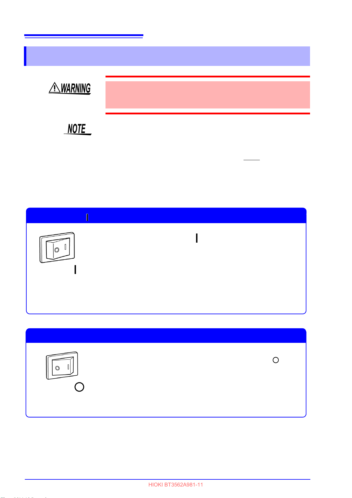
22
Turn on the main power switch on ( ) the rear of the instrument.
The instrument will start up in the standby state in which it was last
turned off. (The instrument ships in the standby state.)
Turning On ( ) the Main Power Switch (Rear of Instrument)
Power ON
Turn off the main power switch on the rear of the instrument.( ).
Turning the Power Off
Power OFF
HIOKI BT3562A981-11
2.4 Turning the Power On and Off
2.4 Turning the Power On and Off
Before turning the instrument on, make sure the supply voltage matches that
indicated on the its power connector. Connection to an improper supply voltage may damage the instrument and present an electrical hazard.
• The measurement setting state is the same as when the power was previously turned off (backup).
To preserve changes to settings, wait a short time (about five seconds) after
changing a setting before turning power off.
• However, measurement settings made through the RS-232C, LAN, or GPIB interface and measurement settings loaded by LOAD
I/O connector are not memorized.
• Before starting to measure, allow 30 minutes for warm-up.
After warm-up, be sure to perform a self-calibration.
See "4.10 Self-Calibration" (p.73).
signals of the EXT

23
Press the power switch on the front of the instrument while it is in the
standby state.
Cancelling the Standby State
(Main Display)
Software version
(Sub Display)
Line frequency
Interface
(Main Display)
Model name
The measurement display appears.
Press and hold the power switch on the front of the instrument for
approximately 1 second while it is in the operating state.
Placing the Instrument in the Standby State
HIOKI BT3562A981-11
2.4 Turning the Power On and Off
2
Chapter 2 Measurement Preparations

24
(Main Display)
(Sub Display)
(Main Display)
(Sub Display)
(Main Display)
(Sub Display) flashing
HIOKI BT3562A981-11
2.5 Selecting the Line Frequency
2.5 Selecting the Line Frequency
The instrument's power supply frequency must be set in order to eliminate noise.
Although the power supply frequency setting is configured automatically ("AUTO") by default, it can also be
set manually. Measured values will not stabilize if the power supply frequency is not set properly.
1
2
3
(The SHIFT indicator lights up.)
The Menu display appears.
Select the Line Frequency setting display.
See "1.4 Menu Display Sequence (SHIFT → ENTER)" (p.16).
Select the frequency of the AC mains supply being used.
4
AUTO .... Automatic configuration of power supply frequency
50 .......... 50 Hz
60 .......... 60 Hz
Applies settings and returns to the Measurement display.
• When set to automatic configuration (AUTO), a power supply frequency of
either 50 Hz or 60 Hz will be automatically detected whenever the instrument is turned on or reset.
• Changes in the power supply frequency occurring at other times will not be
detected.
• The power supply frequency will be set to either 50 Hz or 60 Hz, whichever
is closer.
 Loading...