


BT3554
BT3554-10
BT3554-01
BT3554-11
BATTERY TESTER
Instruction Manual
Oct. 2018 Revised edition 3
BT3554A961-03 18-10H
EN


Battery Tester Quick Guide
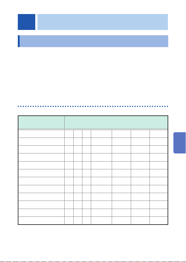
Let's Start by Measuring a New Battery
To determine if a battery is worn out, measure the data of a new
battery. As a battery wears out, its internal resistance increases to
approximately 1.5 to 2 times (reference value) that of a new one.
Use these values as guidelines when determining the battery wear
judgment values.
Example: Changes in the internal resistance and voltage
due to battery wear
Resistance has doubled...
Worn out
1
2
3
4
New battery
Internal resistance: 0.5 m
Voltage: 2.0 V
(The above values are examples.)
Resistance
wear out limit
FAIL
Default value × 2
WARNING
Default value × 1.5
PASS
Default value
BT3554A961-03
Battery requiring replacement
1.0 m
Ω
(twice the value of a
Ω
new battery)
1.8 V (90% of the value of a
new battery)
PassedPassedPassedPassed
Failed
5
6
Internal
resistance
7
Appx. Index
Discharge
capacity

Basic Usage
Connect the test leads to the instrument.
1
Turn the instrument power on.
2
Check the clock settings when using the
instrument for the rst time. (p. 36)
Changing the ranges. (p. 39)
3
Turn on the auto-hold function and auto-
4
memory function.
(
Auto-hold function: Holds measurement values automatically when they
become stable. (p. 75)
Auto-memory function: Automatically stores measurement values
immediately after they are held. (p. 76)
Connect the test leads to the battery.
5
Press the key to read out the
6
measurement values. (p. 69)
and are displayed.)
Data is stored
in internal
memory.
(Black)
Hold at least
1 sec.
(Black)(Red)
−+
(Red)
Handy Features
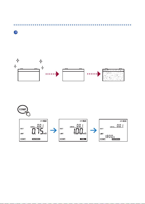
Comparator function
With the comparator function, the threshold values can be set to
determine if the battery is worn out. (p. 55)
1
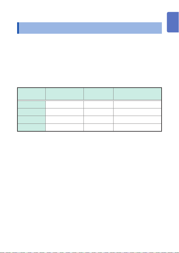
Setting examples of the battery wear judgment values
PASS
(Passing limit)
New battery
Resistance: 0.5 m
Voltage: 2.0 V
(The above values are examples.)
Ω
WARNING
(Warning limit)
In use
0.75 mΩ (1.5 times the
value of a new battery)
1.8 V (90% of the value
of a new battery)
(Failure limit)
Battery requiring
replacement
1.0 mΩ (twice the
value of a new battery)
FAIL
2
3
4
5
6
7
Appx. Index

Downloading measurement values to a computer
By connecting the instrument to a computer with the included USB
cable, the measurement data can be downloaded to the computer.
(p. 83)
Viewing measurement values on a mobile device (only
for BT3554-01)
With the Bluetooth® Communication function, the measurement data
can be viewed on a smart phone or tablet. (p. 84)

Contents
Introduction .........................................................................1
Verifying Package Contents ..............................................2
Options ................................................................................ 4
Safety Information .............................................................. 7
Operating Precautions ..................................................... 12
1 Overview 19
1.1 Measuring Battery Wear ............................... 19
1.2 Overview ........................................................21
1.3 Features .........................................................22
1.4 Names and Functions of Parts .................... 24
1.5 Dimensions .................................................... 29
2 Measurement Preparations 31
2.1 Attaching the Neck Strap ............................. 31
2.2 Installing/Replacing Alkaline Batteries ....... 32
2.3 Connecting the Test Lead .............................33
Connecting a Pin Type Lead and the Model
9466 Remote Control Switch .................................... 34
2.4 Turning the Power ON/OFF ..........................35
2.5 Clock Function .............................................. 36
Turning the Date and Time Display ON/OFF ............ 36
Adjusting the Date and Time .....................................36
1
2
3
4
5
6
7
3 Measurement 37
3.1 Pre-operation Inspection .............................. 38
3.2 Setting the Measurement Range ................. 39
3.3 Adjusting Zero Value
(Zero Adjustment) .........................................40
Appx. Index
8
9
i

Contents
Shorting Methods for Various Test Leads ................. 41
Performing Zero Adjustment ..................................... 44
Zero Adjustment Troubleshooting ............................. 46
Canceling the Zero Adjustment Operation ................46
3.4 Retaining the Displayed Values ................... 47
Canceling the Retaining State ..................................47
When retaining with the Model 9466 Remote
Control Switch ........................................................... 48
3.5 Determining Battery-wear Judgment
Values .............................................................49
3.6 Measuring a Battery (Inspection) ................ 50
Error Measurements ................................................. 52
Warning Display ........................................................52
3.7 Measuring the Temperature .........................53
Changing the temperature display unit ..................... 54
4 Comparator Function (Evaluation by
Threshold Values) 55
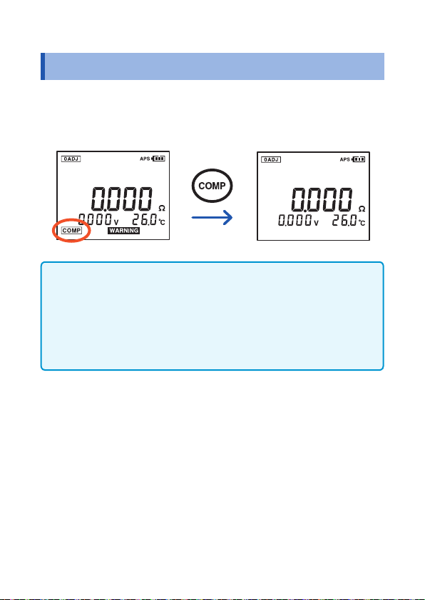
4.1 Overview ........................................................55
4.2 Turning On the Comparator Function .........56
4.3 Setting Threshold Values for the
Comparator .................................................... 57
Comparison Table for the Comparator ...................... 61
4.4 Setting the Comparator Buzzer ................... 63
4.5 Canceling the Comparator Function ........... 64
5 Memory Function 65
5.1 Overview ........................................................65
Memory Structure .....................................................65
5.2 Storing Data in the Memory ......................... 66
5.3 Canceling the Memory Function .................. 68
5.4 Reading Out Stored Data .............................. 69
ii

Contents
5.5 Clearing Stored Data ..................................... 70
Clearing a Single Set of Data ...................................70
Clearing Data from Each Unit ................................... 71
Clearing All Data ....................................................... 72
6 Other Features 73
6.1 Noise Frequency Avoidance Function ........73
6.2 Auto-hold Function ....................................... 75
6.3 Auto-memory Function ................................. 76
6.4 Auto Power Save Function (APS) ................ 77
6.5 Backlight ........................................................ 78
6.6 System Reset ................................................. 79
Default Settings (Factory Defaults) ........................... 80
6.7 Battery Level Warning ..................................81
7 Communications Function 83
7.1 Communicating with a Computer ................ 83
7.2 Communicating with a Smart Phone or
Tablet (Only for BT3554-01) ..........................84
Installing the smartphone app GENNECT Cross ...... 85
Turning ON/OFF the Bluetooth® function .................. 86
Pairing the app with the battery tester (BT3554-01) . 87
Making measurements with the Bluetooth
®
function . 88
Appx.
1
2
3
4
5
6
8 Specications 89
8.1 GeneralSpecications ................................. 89
8.2 BasicSpecications ..................................... 91
8.3 AccuracySpecications ............................... 93
8.4 FunctionalSpecications ............................. 95
8.5 CommunicationSpecications .................. 102
iii
7
8
9

Contents
9 Maintenance and Service 103
9.1 Repair, Inspection, Cleaning ...................... 103
9.2 Troubleshooting ..........................................105
Before Returning for Repair .................................... 105
9.3 Error Messages ........................................... 107
9.4 Frequently Asked Questions ...................... 108
9.5 Replacing the Fuse ..................................... 109
9.6 Replacing the Test Lead’s Tip Pin ............. 110
9.7 Disposing the Instrument (Removing
the Lithium Battery) .................................... 113
Appendix Appx.1
Appx. 1 Effect of Extending the Test Lead
and Induced Voltage ......................... Appx.1
Reducing Induced Voltage ............................Appx.1
Appx. 2 Effect of Eddy Currents.................... Appx.2
Appx. 3 AC 4-terminal Measurement Method .
Appx.3
Appx. 4 Effects of Current Density ............... Appx.5
When the Measurement target is Wide or
Thick .............................................................Appx.5
Appx. 5 Synchronous Detection System...... Appx.7
Appx. 6 Calibration ......................................... Appx.8
Calibrating the Resistance Measurement
Component ...................................................Appx.8
Calibrating the Voltage Measurement Unit ...Appx.9
iv
Introduction
Introduction
Thank you for purchasing the Hioki BT3554, BT3554‑01, BT3554‑10,
BT3554‑11 Battery Tester.
To obtain maximum performance from the instrument, please read
this manual rst, and keep it handy for future reference.
In this document, the model is indicated as BT3554 or BT3554‑01 (as
printed on the instrument), shown below.
Model
BT3554 BT3554 – 9465‑10
BT3554‑01 BT3554‑01
BT3554‑10 BT3554 – L2020
BT3554‑11 BT3554‑01
Model printed on
the instrument
Bluetooth
Standard accessory:
®
9465‑10
L2020
: Yes,
Pin Type Lead
– : No
Trademarks
• Bluetooth® is a registered trademark of Bluetooth SIG, Inc.(USA).
The trademark is used by HIOKI E.E. CORPORATION under
license.
• Android and Google Play are trademarks of Google, Inc.
• IOS is a registered trademark of Cisco Systems, Inc. and/or its
afliates in the United States and certain other countries.
• iPhone, iPad, iPad miniTM, iPad Pro, and iPod touch are
trademarks of Apple Inc.
• The App Store is a service mark of Apple Inc.
1
2
3
4
5
6
7
AppendixIndex
1

Verifying Package Contents
Verifying Package Contents
When you receive the instrument, inspect it carefully to ensure
that no damage occurred during shipping. In particular, check the
accessories, panel switches, and connectors. If damage is evident,
or if it fails to operate according to the specications, contact your
authorized Hioki distributor or reseller.
Conrm that these contents are provided.
(4)
(5)
(3)
(2)
(6)
(7)
(1)
(8)
(9)
2

Verifying Package Contents
(1) Model BT3554 or BT3554‑01 Battery Tester × 1,
Protector × 1 (attached)
(2) Zero adjustment board × 1
(3) Instruction manual*
Emits Radio Waves (only for BT3554‑01) × 1,
Application software*
(4) Carrying Case × 1
(5) Spare fuse × 1
(6) LR6 (AA) alkaline batteries × 8
(7) USB cable × 1
(8) Model 9465‑10 or L2020 Pin Type Lead × 1
(9) Neck strap × 1
*1 Instruction manuals may also be available in other languages.
Please visit our website at http://www.hioki.com.
*2 The latest version can be downloaded from our website.
*3 Apply to battery cover or other location as desired.
1
× 1, Precautions Concerning Use of Equipment That
2
CD × 1, Power‑on option sticker*3 × 1
1
2
3
4
5
6
7
AppendixIndex
3

Options
Options
The following options are available for the instrument. Contact your
authorized Hioki distributor or reseller when ordering.
Model 9772 Pin Type Lead
The lead's pins are arranged parallel to each other. It is a strong,
wear‑resistant lead.
(Red)
(Red)
(Black)
(Black)
Model L2020 Pin Type Lead
This pin type lead has a four-terminal structure and can be used in conned
spaces where the measurement target is difcult to reach.
(Red)
(Red)
(Black)
(Black)
Model 9465-10 Pin Type Lead
This pin type lead has a four‑terminal structure.
(Red)
(Black)
(Black)
(Red)
4

Model 9772-90 Tip Pin
The replacement tip pin for the model 9772 Pin Type Lead.
9.15 mm
1.8 mm
2.5 mm
4.3 mm
φ
Options
1
2
Model 9465-90 Tip Pin
The replacement tip pin for the model 9465‑10 and L2020 Pin Type Lead.
2.7 mm φ1.27 mm
φ
Model 9466 Remote Control Switch
When this switch is attached to the test lead, the instrument can hold the
values while measuring them.
Wearable models: • Model 9465‑10 Pin Type Lead
• Model 9772 Pin Type Lead
• Model L2020 Pin Type Lead
Switch
Miniplug φ2.5 mm
(EXT.HOLD)
3
4
5
6
7
AppendixIndex
5

Options
Model Z5038 0 ADJ Board
Hook and loop fastener is necessary seperately to stick to the carrying case
and use model Z5038.
(For models 9772, L2020, and 9465‑10)
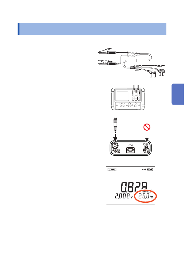
Model 9460 Clip Type Lead with Temperature Sensor
Resistance, voltage, and temperature can be measured simultaneously with
this lead.
(Red)
Temperature
sensor
(Black)
Miniplug
(TEMP SENSOR)
(Red)
(Black)
Model 9467 Large Clip Type Lead
These can clip the test lead to the measurement target with a thick bar. Four‑
terminal measurement can be conducted just by clipping the lead to the target.
(Red)
(Red)
Approx.
29 mm
φ
6
(Black)
Approx. 850 mm
Approx. 250 mm
(Black)

Safety Information
Safety Information
This instrument is designed to conform to IEC 61010 Safety
Standards, and has been thoroughly tested for safety prior to
shipment. However, using the instrument in a way not described in
this manual may negate the provided safety features.
Before using the instrument, be certain to carefully read the
following safety notes:
DANGER
Mishandling during use could result in injury or death,
as well as damage to the instrument. Be certain that
you understand the instructions and precautions in
the manual before use.
WARNING
With regard to the electricity supply, there are risks of
electric shock, heat generation, re, and arc ash due
to short circuits. If persons unfamiliar with electricity
measuring instrument are to use the instrument,
another person familiar with such instruments must
supervise operations.
Protective gear
WARNING
This instrument is measured on a live line. To prevent
electric shock, use appropriate protective insulation
and adhere to applicable laws and regulations.
1
2
3
4
5
6
7
AppendixIndex
7

Safety Information
Notation
In this document, the risk seriousness and the hazard levels are
classied as follows.
DANGER
WARNING
CAUTION
IMPORTANT
Indicates an imminently hazardous situation that
will result in death or serious injury to the operator.
Indicates a potentially hazardous situation that may
result in death or serious injury to the operator.
Indicates a potentially hazardous situation that may
result in minor or moderate injury to the operator or
damage to the instrument or malfunction.
Indicates information related to the operation of the
instrument or maintenance tasks with which the
operators must be fully familiar.
Indicates a high voltage hazard.
If a particular safety check is not performed or the
instrument is mishandled, this may give rise to a
hazardous situation; the operator may receive an
electric shock, may get burnt or may even be fatally
injured.
Indicates prohibited actions.
Indicates the action which must be performed.
8
HOLD
[HOLD]
Indicates a control key.
Indicates the display on the screen.

Symbols on the instrument
Safety Information
Indicates cautions and hazards. When the symbol is printed on
the instrument, refer to a corresponding topic in the Instruction
Manual.
Indicates a fuse.
Indicates a grounding terminal.
Indicates DC (Direct Current).
Symbols for various standards
Indicates the Waste Electrical and Electronic Equipment
Directive (WEEE Directive) in EU member states.
Indicates that the product conforms to regulations set out by the
EU Directive.
Indicates that the product incorporates Bluetooth® wireless
technology.
FCC ID
FCC ID Indicates the ID number of the wireless module certied
by the U.S. Federal Communications Commission (FCC).
Indicates the identication number of a wireless module
IC
approved by Industry Canada (IC).
1
2
3
4
5
6
7
AppendixIndex
9

Safety Information
Screen Display
The instrument screen displays the alphanumeric characters as
follows.
A B C D E F G H I J K L M N O P Q R S T U V W X Y Z
1 2 3 4 5 6 7 8 9 0
A different display is used in the case below:
Displays when setting the Bluetooth
:
communication.
: Displays when clearing the stored data.
Displays when setting the comparator buzzer
:
to FAIL.
Accuracy
We dene measurement tolerances in terms of f.s. (full scale), rdg.
(reading) and dgt. (digit) values, with the following meanings:
(maximum display value or range)
f.s.
The maximum displayable value. This is usually the name of the
currently selected range.
(reading or displayed value)
rdg.
The value currently being measured and indicated on the
measuring instrument.
(resolution)
The smallest displayable unit on a digital measuring instrument,
dgt.
i.e., the input value that causes the digital display to show a "1" as
the least-signicant digit.
®
10

Safety Information
Measurement Categories
To ensure safe operation of measuring instruments, IEC 61010
establishes safety standards for various electrical environments,
categorized as CAT II to CAT IV, and called measurement categories.
DANGER
• Using a measuring instrument in an environment
designated with a higher category than the rating
of the instrument could result in a severe accident,
and must be carefully avoided.
• Using a measuring instrument without categories
in an environment categorized as CAT II to CAT
IV could result in a severe accident, and must be
carefully avoided.
CAT II: When directly measuring the electrical outlet receptacles of the
primary electrical circuits in equipment connected to an AC electrical
outlet by a power cord (portable tools, household appliances, etc.).
CAT III: When measuring the primary electrical circuits of heavy equipment
(xed installations) connected directly to the distribution panel, and
feeders from the distribution panel to outlets.
CAT IV: When measuring the circuit from the service drop to the service
entrance, and to the power meter and primary overcurrent protection
device (distribution panel).
Distribution panel
Service entrance
Service drop
CAT IV
Power meter
Fixed installation
The instrument’s labeling does not indicate its suitability for use in any
particular measurement category.
Internal wiring
CAT III
CAT II
T
Outlet
1
2
3
4
5
6
7
AppendixIndex
11

Operating Precautions
Operating Precautions
Follow these precautions to ensure safe operation and to obtain the
full benets of the various functions.
Ensure that your use of the product falls within the specications not
only of the instrument itself, but also of any accessories, options,
batteries, and other equipment being used.
Installing the instrument
CAUTION
Installing the instrument in inappropriate locations may
cause a malfunction of instrument or may give rise to an
accident. Avoid the following locations.
• Exposed to direct sunlight or high temperature
• Exposed to corrosive or combustible gases
• Exposed to a strong electromagnetic eld or electrostatic
charge
• Near induction heating systems (such as high‑frequency
induction heating systems and IH cooking equipment)
• Susceptible to vibration
• Exposed to water, oil, chemicals, or solvents
• Exposed to high humidity or condensation
• Exposed to high quantities of dust particles
Do not place the instrument on an unstable table or an
inclined place. Dropping or knocking down the instrument
can cause injury or damage to the instrument.
12

Preliminary checks
Operating Precautions
DANGER
If the test lead or the instrument is damaged, there is
a risk of electric shock. Before using the instrument
perform the following inspection:
• Before using the instrument check that the coating
of the test leads are neither ripped nor torn and that
no metal parts are exposed. Using the instrument
under such conditions could result in electric
shock. Replace the test leads with those specied
by our company.
• Verify that the instrument operates normally to
ensure that no damage occurred during storage
or shipping. If you nd any damage, contact your
authorized Hioki distributor or reseller.
Precautions for Transportation
During shipment of the instrument, handle it carefully so that it is not
damaged due to a vibration or shock.
Handling the instrument
DANGER
To avoid electric shock, do not remove the
instrument's case. The internal components of the
instrument carry high voltages and may become very
hot during operation.
1
2
3
4
5
6
7
AppendixIndex
13

Operating Precautions
CAUTION
To avoid damage to the instrument, protect it from physical
shock when transporting and handling. Be especially
careful to avoid physical shock from dropping.
Precautions for measurement
DANGER
To avoid electric shock, be careful to avoid shorting
live lines with the test leads.
WARNING
• Do not use the instrument and test lead with circuits
that exceed its ratings or specications. Doing so
may cause damage, resulting in an electric shock.
• Do not measure any voltage that would exceed the
instrument’s maximum input voltage (terminal-toterminal) or maximum rated terminal-to-ground
voltage of 60 V.
Maximum input voltage
(terminal-to-terminal) 60 V DC
Maximum rated terminalto-ground voltage 60 V DC
14
• Do not measure AC voltage.

Operating Precautions
WARNING
• Be sure to connect the test lead correctly.
• Wear gloves of rubber or similar material during
measurement.
• Ensure sufcient ventilation when measuring
batteries in the measurement room to prevent
explosions. Sparks may occur when the test leads
are connected to batteries, which can ignite any
accumulated inammable gases such as hydrogen.
1
2
CAUTION
• After measuring a high-voltage battery, rst short the
test leads together to discharges the DC elimination
capacitor connected across the leads before continuing
to measure a low‑voltage battery. Otherwise an excess
voltage may be applied to the low‑voltage battery
causing damage to the battery.
• To avoid damage to the instrument, do not apply voltage
to the EXT.HOLD and TEMP.SENSOR terminal.
IMPORTANT
Do not place the test leads in contact with the measurement
terminals of a battery that is leaking uid. Doing so may cause
a degradation in instrument functionality due to exposure to
electrolyte from the leaking battery.
3
4
5
6
7
AppendixIndex
15

Operating Precautions
Handling the test leads
CAUTION
Do not apply force when the pin type lead tip is in contact
with the battery at a tilted angle.
OK NO
Avoid subjecting the temperature probe tip to physical
shock, and avoid sharp bends in the leads. These may
damage the probe or break a wire.
IMPORTANT
When using the instrument, use only the test leads with those
specied by our company. Using other test leads may result
in incorrect measurements due to loose connections or other
reasons.
Zero adjustment board
WARNING
To prevent short-circuit accidents, do not place the
zero adjustment board on top of the battery.
16

Batteries and fuses
Operating Precautions
WARNING
• To avoid electric shock when replacing the batteries
and fuse, rst disconnect the test leads from the
object to be measured, and then remove the case.
• To prevent instrument damage or electric shock,
use only the screw for securing the battery cover
in place that are originally installed. If you have lost
a screw or nd that a screw is damaged, please
contact your Hioki distributor for a replacement.
• Replace the fuse only with one of the specied type,
characteristics, rated current, and rated voltage. Do
not use fuses other than those specied (especially,
do not use a fuse with higher-rated current) or do
not short circuit and use the fuse holder. Doing so
may damage the instrument and result in bodily
injury.
Fuse type: 216.630, Littelfuse Inc., fast-acting, rating
250 V / F 630 mAH, circuit breaker rating 1500 A
• Battery may explode if mistreated. Do not short-
circuit, recharge, disassemble or dispose of in re.
1
2
3
4
5
6
7
AppendixIndex
17

Operating Precautions
CAUTION
Poor performance or damage from battery leakage could
result. Observe the cautions listed below:
• Do not mix old and new batteries, or different types of
batteries.
• Be careful to observe the battery polarity during
installation.
• Do not use batteries after their recommended expiry
date.
• Do not allow weak batteries to remain in the instrument.
• Replace batteries only with the specied type.
• Remove the batteries from the instrument if it is to be
stored for a long time.
Handle and dispose of batteries in accordance with local regulations.
CD disc precautions
• Exercise care to keep the recorded side of discs free of dirt
and scratches. When writing text on a disc's label, use a pen or
marker with a soft tip.
• Keep discs inside a protective case and do not expose to direct
sunlight, high temperature, or high humidity.
• Hioki is not liable for any issues your computer system
experiences in the course of using this disc.
18

1
Overview
1.1 Measuring Battery Wear
IMPORTANT
To determine if a battery is worn out, rst measure the internal
resistance of a new or good battery.
When the battery is worn out, the internal resistance rises to
approximately 1.5 to 2 times its default value (reference values).
The graph below shows the relation between storage capacity and
default value of internal resistance in a lead-acid battery. "CS",
"HS", and "MSE" denote JIS (Japanese Industrial Standard) leadacid battery types.
The internal resistance of an MSE (sealed stationary lead-acid
battery) can be read at approximately 1 m
approximately 0.13 m
]
[m
Ω
10
1
0.1
Internal resistance value
(1000 Ah).
Ω
CS
HS
MSE
CS Clad type stationary lead-acid
HS High discharge rate stationary
MSE Sealed stationary lead-acid
(100 Ah) and
Ω
battery
lead-acid battery
battery
1
2
3
4
5
6
7
Appx. Index
0.01
10 100 1000 10000
Lead-acid battery capacity
[Ah]
19

Measuring Battery Wear
• The warning limit (WARNING) for an MSE (sealed stationary
lead-acid battery) is when the internal resistance reaches
approximately 1.5 times its default value. The failure limit (FAIL)
varies for each manufacturer.
• Default value of internal resistance may vary among batteries
with the same capacity, depending on the model or manufacturer.
Use the graph on the previous page as reference.
• Internal resistance warning limit (WARNING) and failure limit
(FAIL) varies for each manufacturer.
Source: Battery technician certication textbook, Battery Association
of Japan (BAJ)
Comparator function (p. 55)
With the comparator function, the battery measurement values
can be compared with the present threshold values to determine
which ranges those values fall within: PASS, WARNING, or FAIL.
In open (liquid) stationary lead-acid batteries such as CS, HS, and
alkaline lead-acid batteries, variations in internal resistance are
small compared with sealed stationary lead-acid batteries, and
sometimes it is difcult to determine worn out state of the batteries.
20

Overview
1.2 Overview
This instrument measures internal resistance, voltage, and terminal
temperature* of lead-acid, nickel-cadmium, nickel-hydrogen, and
other types of batteries, enabling you to determine if the battery is
worn out.
1
2
3
* Temperature measurement requires the optional model 9460 Clip
Type Lead with Temperature Sensor.
The measurement data can be copied to a computer by connecting
the instrument to a computer after measurement with the USB cable
provided. Also, users can view the data on their smart phones or
tablets with the Bluetooth® Communication function.
Measurement data
Specifying
threshold values
Measurement data
21
4
5
6
7
Appx. Index

Features
1.3 Features
Enables measurement without shutting down UPS
systems
This instrument uses high-precision AC resistance measurement
technology, and noise reduction technology. Time required for
measurement is reduced since the instrument is capable of
measuring live wires without requiring the UPS system to be shut
down.
Reliable measurement values
This instrument is capable of obtaining reliable measurement values
without being affected by lead or connector resistance because it
uses the AC 4-terminal method to measure internal resistance.
Simultaneous display of resistance, voltage, and
temperature
Without changing functions, this instrument can display
battery internal resistance, voltage, and terminal temperature
simultaneously. Temperature measurement requires the optional
model 9460 Clip Type Lead with Temperature Sensor.
Comparator function
The comparator function enables you to set threshold values for
internal resistance and voltage. This can determine battery wear
more easily.
Large memory capacity
This instrument can store up to 6000 sets of data combining
presently measured values (resistance, voltage, temperature, and
comparator measurement results). It can be used to measure up to
12 units of 500-cell cubicles.
22

Features
Auto-memory function
Turning this function on stores the measurement values in the
instrument's internal memory automatically, the instant when each
set of data is held. This can lead to increased operational efciency.
PC interface
Measurement data can be loaded into a computer.
Bluetooth® Communication function
Users can view measurement values on their smart phones and
tablets.
Model L2020 Pin Type Lead (optional)
The model L2020 pin type lead is L-shaped and handy to measure
in conned location.
Model 9772 Pin Type Lead (optional)
Using the model 9772 Pin Type Lead with a pin tip designed to t
in holes of φ5 mm enables measurement without removing terminal
covers. Measurement is possible in virtually any location because
the pin can be inserted diagonally in hard-to-reach places.
Model 9466 Remote Control Switch (optional) for
storing measurement values
The model 9466 Remote Control Switch makes it possible to hold
and store measurement values by pressing a key. This is useful
when both hands of the operator are busy.
1
2
3
4
5
6
7
Appx. Index
23

Names and Functions of Parts
1.4 Names and Functions of Parts
Front
Display (p. 27)
Measurement
terminals
Control keys
(BT3554-01)
Measurement terminals
(1)
(p. 14, p. 33)
(1) SOURCE
terminals
(2) SENSE
terminals
24
(2)
The SOURCE side of the banana plug on the test
lead is connected to this terminal.
The SENSE side of the banana plug on the test
lead is connected to this terminal.

Control keys
Names and Functions of Parts
Pressing
−
Turns the comparator
buzzer ON/OFF.
Turns the comparator ON/
OFF.
Turns the auto-hold and
auto-memory features ON/
OFF.
Displays the clock. Adjusts the clock. −
Selects a conguration
setting.
Changes the value.
Uses the right or left key
to select a digit.
Turns on the memory
storage.
Stores measurement value
when it is retained.
Conrms the settings. −
Holds or cancels the
measurement values.
Reads or cancels stored
measurement values.
Deletes the settings.
Pressing and
holding (at
least 1 second)
Turns the power
ON/OFF.
− −
Sets comparator
threshold values.
−
− −
Turns off the
memory storage.
−
− −
Deletes the last
stored data.
Pressing and
holding the key
while turning on
the power
Displays the setup
screen for the
disconnection
detection function.
Turns the
Bluetooth
Communication
function ON/OFF
(for BT3554-01).
Displays the Serial
No.
Displays the APS
setup screen.
Displays the system
reset screen.
1
−
−
2
3
4
5
®
6
7
Appx. Index
25

Names and Functions of Parts
Pressing
−
Turns the backlight ON/
OFF.
Changes the resistance
range.
Changes the voltage
range.
Pressing and
holding (at
least 1 second)
Starts or cancels
zero adjustment.
(press and hold
for at least 2
seconds.)
− −
−
−
Pressing and
holding the key
while turning on
the power
−
Displays the setup
screen for the
noise frequency
avoidance function.
Displays all LCD
screen elements.
26

Display
Names and Functions of Parts
Data No.
Resistance
measurement
value and units
Voltage
measurement
value and
units
Zero adjustment ON
Clock display and setting
Comparator buzzer ON
Now communicating
Bluetooth® function ON
(only for BT3554-01)
Auto Power Save ON
Battery level
Auto-hold ON
Auto-memory ON
Noise frequency
avoidance function ON
Input overow
Retain measurement
value
Indicators other than those shown above may also light up when all the
indicators on the display are shown, but only the above indicators are used by
the instrument.
Temperature
measurement
value and units
Saved memory number
Read memory number
Comparator number
Selected memory
number is in use
Setting each function
For setting comparator
threshold values
For noise frequency
avoidance function
Comparator ON
PASS result
WARNING result
FAIL result
1
2
3
4
5
6
7
Appx. Index
27

Names and Functions of Parts
Top view
(1) (2) (3)
(1) EXT.HOLD terminal Connects the model 9466 Remote
(2) USB terminal Connects the USB cable.
(3) TEMP.SENSOR terminal Connects the miniplug of the model 9460
Control Switch (optional).
Clip Type Lead with Temperature Sensor
(optional).
Rear view
Fuse cover
Tightening screw
Serial No.*
Bluetooth
(only for BT3554-01)
®
label
Battery cover
* The serial number consists of 9 digits. The rst two (from the left)
indicate the year of manufacture, and the next two indicate the
month of manufacture. Required for production control. Do not
peel off the label.
(p. 17)
(p. 17)
28

1.5 Dimensions
Dimensions
1
60.6±3 mm
132±3 mm
2
199±3 mm
3
4
5
6
7
Appx. Index
29

Dimensions
30

Measurement Preparations
2
2.1 Attaching the Neck Strap
Operators can hang the instrument around their neck by attaching
the neck strap. Attach the neck strap as described below.
Switch off the instrument and
1
remove the test leads.
Pass the neck strap through
2
the 2 attachments and fasten it
in place with the buckles (2 on
each side of the instrument).
Adjust the length of the neck
3
strap.
The instrument can be placed in
the carrying case even with the
neck strap attached.
1
2
3
4
5
6
7
Appx. Index
31

Installing/Replacing Alkaline Batteries
2.2 Installing/Replacing Alkaline Batteries
When using the instrument for the rst time, insert 8 LR6 (AA)
alkaline batteries. Before attempting measurement, check to make
sure that the battery level is sufcient. If the battery level is low,
replace the batteries with new ones.
• The indicator ashes when alkaline battery voltage
becomes low. Replace the batteries as soon as possible.
• In this document, the "alkaline battery" means the LR6 (AA)
battery to run the instrument, and the "battery" refers to the
measurement target.
Switch off the instrument and
1
remove the test leads.
1
Open the alkaline battery cover
2
on the rear of the instrument.
Insert 8 alkaline batteries, taking
3
care of the proper polarities.
Replace the alkaline battery
4
cover.
32
3
4
2

Connecting the Test Lead
2.3 Connecting the Test Lead
WARNING
To avoid electric shocks, be sure to connect the test
leads properly.
Connect the test leads to the instrument. Be sure to connect all 4
terminals: SOURCE (+,−) and SENSE (+,−).
(Black)
(Red)
Align the
marks of the
same color.
When using the optional model 9460 Clip Type Lead with
Temperature Sensor, connect the miniplug to the TEMP.SENSOR
terminal. For more information, see “Measuring the Temperature” (p.
53).
1
2
3
4
5
6
7
Appx. Index
33

Connecting the Test Lead
Connecting a Pin Type Lead and the Model 9466 Remote Control Switch
The Pin Type Lead (Models 9465-10, 9772, and L2020) and the
optional model 9466 Remote Control Switch can be combined
together as shown below.
Connect the remote control switch to the probe of the lead, and join
the 2 cables using the supplied spiral tube.
(1) (2) (3) (4)
(L2020)
(4)(5)
(1) Model 9446 Remote Control Switch
(2) Probe
(3) Spiral tube (small)
Bundle up the center of the lead between the probe and junction
with a spiral tube.
(4) Junction
(5) Spiral tube (large)
Arbitrarily bundle up the lead between junctions.
34
(9465-10)

Turning the Power ON/OFF
2.4 Turning the Power ON/OFF
Press and hold the key (for at least 1 second) to turn the
power on or off. Check the clock settings when using the instrument
for the rst time.
1
Power: ON Power: OFF
The indicator ashes when alkaline battery voltage
becomes low. Replace the batteries as soon as possible.
2
3
4
5
6
7
Appx. Index
35

Clock Function
2.5 Clock Function
The date and time can be displayed by pressing the DATE key.
Check the clock settings when using the instrument for the rst
time. The time is displayed using a 24-hour clock. The instrument's
calendar recognizes leap years automatically.
Turning the Date and Time Display ON/OFF
Press the DATE key to switch date-and-time display on or off.
Date and time display: ON Date and time display: OFF
Year
Month
Time
Day
(00:00 on January 1, 2016)
Adjusting the Date and Time
1
2
3
36
(Press the key for at least
1 second.)
Enters the date and time
setup mode.
Select the values.
Conrm the specied
values.
Date and time will not be set if
you exit the clock setup screen
without pressing the ENTER key.

Measurement
3
To ensure safe operation, be sure to read "Operating Precautions" (p.
12) before starting the measurements.
• Internal battery resistance varies considerably depending
on charge or discharge status. To increase measurement
accuracy, make measurements under similar conditions (for
example, a fully charged battery).
• Lead-acid batteries (measuring objects) have high levels of
terminal resistance. For this reason, resistance values may
differ between the case and the tip of the terminal. Be sure to
connect the test lead to the terminals at a xed location.
For more information, see "Effects of Current Density" (p. Appx.5).
• Use the optional model 9460 Clip Type Lead with Temperature
Sensor to measure the battery temperature. Or, use a noncontact thermometer, such as a radiation thermometer, for
safety.
• Measurement may not be possible for insulated terminals, due
to insufcient ow of current for measurement. In such a case,
clean the terminal (remove the insulation) before measurement.
1
2
3
4
5
6
37
7
Appx. Index

Pre-operation Inspection
3.1 Pre-operation Inspection
Before using the instrument, verify that it operates normally to
ensure that no damage occurred during storage or shipping. If
you nd any damage, contact your authorized Hioki distributor or
reseller.
Inspection item Method of checking
Is the fuse burned
out?
Is the test lead
disconnected?
Touch the test lead to the zero adjustment board.
If the resistance display still shows [−−−−], the
fuse might be burned out or the test lead may be
disconnected. If so, replace it with a new one.
Is the battery level
sufcient?
Inspecting
batteries
38
At the upper right-hand area of the screen,
indicates the present alkaline battery status. If
is displayed, the alkaline batteries need to
be replaced soon. Be sure to have spare alkaline
batteries available.
Measurement may not be possible for insulated
terminals, due to insufcient ow of current for
measurement. In such a case, clean the terminal
(remove the insulation) before measurement.

Setting the Measurement Range
3.2 Setting the Measurement Range
Set resistance and voltage measurement ranges as described
below.
Resistance range 3 m
Voltage range 6 V/ 60 V
Temperature range
/30 mΩ/300 mΩ/3
Ω
(Single range)
Because temperature measurement uses a signal
range, range setting is not required.
Ω
1
2
Press the Ω key or V key to display the present settings. Press the
key repeatedly to cycle through the ranges.
Resistance range
3.000 m
Voltage range
6.000 V
When there is no activity for approximately 1 second, the settings on
the display get conrmed and returns to the measurement screen.
3.000
Ω
Ω
30.00 m
300.0 m
60.00 V
Ω
Ω
39
3
4
5
6
7
Appx. Index

Adjusting Zero Value (Zero Adjustment)
3.3 Adjusting Zero Value (Zero Adjustment)
The zero adjustment function displays subsequent measurement
results using the measured value (correction value) obtained when
it was performed as zero.
The dened accuracy does not require zero adjustment to be
performed when using accessory or optional test leads, but the
process should be performed in the following instances:
• When you wish to increase measurement accuracy*
• When using test leads that are not an accessory or option, or
when using test leads whose length has been extended
* For the 3 m
on whether zero adjustment has been performed.
For more information, see "8 Specications" (p. 89).
• Performing zero adjustment adjusts the zero points of all
ranges.
• Even after the instrument is turned off, the correction values
are retained and the zero adjustment function is not canceled.
• After replacing the test lead, be sure to perform zero adjustment
prior to measurement.
• Be sure to use the included or optional zero adjustment board
when performing zero adjustment.
• Be sure to keep the test lead shorted during zero adjustment.
• Keep the tip of the test lead away from the metal components.
range, the accuracy specications differ depending
Ω
40

Adjusting Zero Value (Zero Adjustment)
Shorting Methods for Various Test Leads
For Pin Type Leads
Use the included or optional zero adjustment board. The zero
adjustment can be achieved using the AC 4-terminal method.
Select 2 holes on the zero
1
adjustment board which are
at the same distance as the
terminals on the battery to be
measured.
Push the test leads in a direction perpendicular to the
2
holes so that it is symmetrical to the central plus sign (+)
on the zero adjustment board.
Model 9465-10 or L2020 Pin Type Lead
1
2
3
4
Center the plus sign (+).
Model 9772 Pin Type Lead
Insert the marked (engraved)
side into the hole.
5
6
7
Appx. Index
41

Adjusting Zero Value (Zero Adjustment)
• Keep the zero adjustment board at least 10 centimeters away
from the instrument.
• Be sure to use the included or optional zero adjustment board
when performing zero adjustment.
• Be sure to connect each of the SOURCE and SENSE terminals
by inserting the tip of the pin into the holes on the zero
adjustment board. (See the gure below.)
SOURCE
SENSE
• Do not place the zero adjustment board on top of the battery
or any metal. Electromagnetic induction effect could result in
unstable measurement values. In such a case, keep the zero
adjustment board away from any metal.
• Performing zero adjustment by connecting the tips of pin-
type leads or using a metal sheet other than the included zero
adjustment board will result in inaccurate adjustment of the
zero point.
• When the distance between the terminals on the battery
(measurement target) is more than the distance between the
holes on the zero adjustment board, use the holes at both
corners to perform zero adjustment.
• Consider the zero adjustment board to be a consumable.
Replacing it with a new one after using it around 700 times is
recommended.
42

Adjusting Zero Value (Zero Adjustment)
For Clip Type Leads
Perform zero adjustment by engaging red and black clips together.
Model 9460 Clip Type Lead with Temperature Sensor
SOURCE
SENSE
Model 9467 Large Clip Type Lead
SOURCE
SENSE
1
2
3
4
5
6
7
Appx. Index
43

Adjusting Zero Value (Zero Adjustment)
Performing Zero Adjustment
Check to ensure that the test
1
leads are connected properly.
Disconnect any leads connected
to the measurement target.
Press the 0ADJ key for at least
2
2 seconds.
This enables the standby state for
acquiring the correction values.
While [0AdJ] is ashing, short
3
the test leads using the zero
adjustment board.
For more information, see
"Shorting Methods for Various
Test Leads" (p. 41).
If the test leads are not shorted
while the display is blinking, it will
result in an error.
(Black) (Red)
1
2
Press for at
least 2 sec.
Flashes for approx.
10 secs.
For pin type leads
44

Adjusting Zero Value (Zero Adjustment)
The instrument automatically begins obtaining correction values.
When the zero adjustment operation is complete, [0ADJ] is lit
up and the instrument returns to the measurement mode:
1
2
3 mΩ range 30 mΩ range
Zero adjustment
complete
• Keep the test leads shorted until the zero adjustment operation
is complete.
• The zero adjustment starts even if a key is pressed after the
test lead has been shorted.
300 mΩ range
3
range and voltage
Ω
range
3
4
5
6
7
Appx. Index
45

Adjusting Zero Value (Zero Adjustment)
Zero Adjustment Troubleshooting
Check items Solution
Is the fuse burned out? If so, replace it with a new fuse. (p. 109)
Do the correction
values obtained exceed
300 counts in either
resistance or voltage
range?
Did you short the test
leads properly while the
instrument is in standby
for correction values?
Ensure that the test lead is properly connected
to the instrument.
The test lead may be disconnected. If so,
replace it with a new one.
Try cleaning the zero adjustment board.
While the instrument is in standby for correction
values (for approximately 10 seconds), short
the test leads using the zero adjustment board
to perform zero adjustment.
Canceling the Zero Adjustment Operation
Pressing the 0ADJ key for at least 2 seconds while the zero
adjustment function is active, cancels the zero adjustment operation.
Zero adjustment: ON Zero adjustment: OFF
Press for
at least 2
seconds.
46

Retaining the Displayed Values
3.4 Retaining the Displayed Values
• When the warning display or voltage is displayed as [−−−−],
the values cannot be retained.
• Changing any of the settings cancels retaining.
• Turning off the power cancels retaining.
Measurement values displayed on the screen can be retained.
Pressing the HOLD key will light up [HOLD], and retain the
measurement values.
Retaining function: OFF Retaining function: ON
Canceling the Retaining State
Pressing the HOLD key again cancels the retaining state.
The auto-hold function can be used to automatically recognize
the stability of measurement values and retain them. For more
information, see "6.2 Auto-hold Function" (p. 75).
1
2
3
4
5
6
7
Appx. Index
47

Retaining the Displayed Values
NO
NONO
When retaining with the Model 9466 Remote Control Switch
The optional model 9466 Remote
Control Switch is available for the
operation in the same way as when
using the HOLD key.
Disconnect the test leads from
1
the battery (measurement
target).
Insert the miniplug of the model
2
9466 Remote Control Switch
into the EXT.HOLD terminal.
Connect the connectors of the
3
test leads to the instrument.
Press the PRESS button on the
4
model 9466 Remote Control
Switch.
The measurement value is
retained.
Model 9466 Remote
Control Switch
Top of the instrument
(Black) (Red)
Canceling the retaining state
Press the PRESS button on the model 9466 Remote Control
Switch, or the HOLD key on the instrument.
48

Determining Battery-wear Judgment Values
3.5 Determining Battery-wear Judgment Values
To determine if a battery is worn out, rst measure the internal
resistance of a new or good battery, and decide the limits for judging
battery wear.
As a battery wears out, its internal resistance increases to
approximately 1.5 to 2 times (reference value) that of a new or
good battery, and voltage values decreases to 90% of the default
value. Use these values as guidelines when determining the battery
wear judgment values.
Example of the battery wear judgment values
Default value
(PASS)
Warning limit
(WARNING)
Failure limit
(FAIL)
1
2
3
4
5
Resistance:
Voltage:
The above values are examples.
The above values vary depending on the manufacturer and
battery model. For more information, see "1.1 Measuring Battery
Wear" (p. 19).
0.5 m
Ω
2.0 V 1.8 V
0.75 m
Ω
1.0 m
Ω
6
7
Appx. Index
49

Measuring a Battery (Inspection)
3.6 Measuring a Battery (Inspection)
Prepare the measurement. (p. 31)
1
Set the resistance and voltage ranges. (p. 39)
2
Perform zero adjustment. (p. 40)
3
Connect the test leads to the battery.
4
Ensure that all pins are
connected to the battery.
(Red)
+
Read the measurement values.
5
50
(Black)
−
Internal resistance of the battery
Voltage

Measuring a Battery (Inspection)
Use the measurement values to judge whether the battery
6
is worn out.
Example:
Voltage
1
Default
value
(2.0 V)
Current
value
(1.8 V)
As shown above, this battery needs to be replaced.
To retain
measurement values
To store
measurement values
To load the stored
data to a computer
To set threshold
values and judge
whether the battery
is worn out
PASS
WARNING
Default value
(0.5 mΩ)
Refer to "3.4 Retaining the Displayed
Values" (p. 47).
Measurement values can be stored
by pressing the MEMO key while the
values are being retained.
Refer to "5.2 Storing Data in the
Memory" (p. 66).
Refer to "Communications Function" (p.
83).
Based on the wear judgment values,
threshold values can be set for judging
whether the battery is worn out.
Refer to "Comparator Function
(Evaluation by Threshold Values)" (p.
55).
Present value
(1.0 m
FAIL
FAIL
Resistance
)
Ω
2
3
4
5
6
7
Appx. Index
51

Measuring a Battery (Inspection)
Error Measurements
If [−−−−] is displayed and [OVER] ashes on the screen (at the
same time, the maximum display values ashes), this does not
indicate an error.
[
] • If [
−−−−
[OVER] display
and maximum
display value
ashes
• The test lead is not connected correctly to the
• The resistance of the measurement target signicantly
• This indicates that it is measuring an exceeded
] is shown in the resistance display, the test
−−−−
lead is open.
Or, a failure such as abnormal current ow due to a
disconnected test lead prevents measurements.
measurement target.
exceeds the measurement range.
measurement range of either resistance, voltage, or
temperature.
Note the maximum open-circuit terminal voltage of the instrument
(approximately 5 V maximum) when measuring the resistance
of a relay or a connector. There is a possibility that such
measurement may damage the oxidized coating on the connector
of the measurement target, leading to incorrect measurements.
Warning Display
In the event of an overvoltage input error, the [OVER] display and
maximum display value ash, the red backlight lights up, and the
buzzer sounds.
52
Measuring the Temperature
NO
NONO
3.7 Measuring the Temperature
Use the optional model 9460
Clip Type Lead with Temperature
Sensor to measure the battery
temperature.
Connect the connector of
1
the model 9460 Clip Type
Lead with Temperature
Sensor to the instrument.
Connect the miniplug of the
2
model 9460 Clip Type Lead
with Temperature Sensor to
the TEMP.SENSOR terminal.
The instrument detects the
temperature sensor and
automatically displays the
temperature.
1
2
(Black) (Red)
3
4
5
Top of the instrument
6
7
Appx. Index
53

Measuring the Temperature
Changing the temperature display unit
The units of temperature (°C or °F) can be changed.
1
2
3
4
The setting of the temperature unit is retained even after the
power is turned off.
Turn off the instrument.
Display the setting of the
temperature unit.
Press the key for at least 3
seconds.
Conrm the setting.
The instrument is restarted.
The settings will not change if
the power is turned off before the
settings are applied.
54

Comparator Function
4
(Evaluation by Threshold Values)
4.1 Overview
The battery measurement values can be compared with the present
threshold values using the comparator function to determine the
ranges in which the values fall within: PASS, WARNING, or FAIL.
Up to 200 comparator conditions can be set. Refer to “Measuring
Battery Wear” (p. 19) for more information on how to determine
the threshold values.
A buzzer sounds when a measurement falls within the range of
WARNING or FAIL under the default settings. For more information,
see “4.4 Setting the Comparator Buzzer” (p. 63).
A resistance warning limit, resistance failure limit, and voltage
warning limit are available as the threshold values.
Voltage
PASS
Default value
Voltage
warning limit
WARNING
Default
value
Resistance
warning
limit
FAIL
FAIL
Resistance
failure limit
Resistance
1
2
3
4
5
6
7
Appx. Index
55

Turning On the Comparator Function
4.2 Turning On the Comparator Function
1
2
3
Press the key.
The comparator number ashes.
Press the COMP key again to return
to normal measurements.
Select the comparator
number.
(A number from 1 to 200 can be
selected.)
Conrm the settings.
The comparator function is now
turned on.
When the comparator function is turned on, the instrument
changes to the range specied by the comparator settings.
56

Setting Threshold Values for the Comparator
4.3 Setting Threshold Values for the Comparator
Threshold values can be set for the comparator (resistance warning
limit, resistance failure limit, and voltage warning limit).
1
Example: Threshold values for a battery with the default
values* 0.4
Resistance warning limit: 0.6 Ω (1.5 times of the default value)
Resistance failure limit: 0.8 Ω (2 times of the default value)
Voltage warning limit: 1.8 V
* The default value refers to the value of resistance and voltage for
a new battery or a battery in good condition.
Selecting a comparator number
1
2
3
and 2 V.
Ω
Press the key for at least 1
second.
The comparator number ashes.
Press the COMP key again to return
to normal measurements.
Select the comparator
number.
(A number from 1 to 200 can be
selected.)
Conrm the settings.
The range setup screen is displayed.
2
3
4
5
6
7
Appx. Index
57

Setting Threshold Values for the Comparator
Setting the range
Select the resistance range.
1
2
3
Setting the threshold values
1
(To shift the decimal point)
Select the voltage range.
(To shift the decimal point)
Conrm the settings.
The resistance warning limit and
[WARNING] ashes.
Set the resistance warning
limit.
2
3
58
Conrm the settings.
The resistance failure limit and
[FAIL] ashes.
Set the resistance failure
limit.

4
5
Conrm the settings.
The voltage warning limit and
[WARNING] ashes.
Set the voltage warning limit.
Setting Threshold Values for the Comparator
1
6
• Voltage is determined using absolute values. Comparison is
• If you set the resistance failure limit to a value that is less than
Conrm the settings.
Returns to the measurement screen,
with the comparator function turned
on.
The settings are now saved.
possible even if the positive and negative electrodes of the
test lead are connected to negative and positive terminals,
respectively. (Data is stored with the sign.)
the resistance warning limit as previously set, the warning limit
will be set to the same value as the new failure limit.
2
3
4
5
6
7
Appx. Index
59

Setting Threshold Values for the Comparator
When a measurement value is determined as "PASS"
Voltage
PASS
Default value
Voltage
warning limit
Measurement
value
WARNING
FAIL
FAIL
Default
value
Resistance
warning
limit
Resistance
failure limit
When a measurement value is determined as
"WARNING"
Voltage
Default value
Voltage
warning limit
PASS
WARNING
Default
value
Measurement
value
Resistance
warning
limit
FAIL
FAIL
Resistance
failure
limit
60
Resistance
Resistance

Setting Threshold Values for the Comparator
When a measurement value is determined as "FAIL"
Voltage
Default value
Voltage
warning limit
PASS
WARNING
Default
value
Resistance
warning
limit
FAIL
Measurement
value
FAIL
Resistance
failure
limit
Resistance
Comparison Table for the Comparator
The result is determined by the display and buzzer as shown in the
following table:
Resistance
warning limit
Resistance
(low)
Voltage (high) PASS WARNING FAIL
Voltage warning limit
Voltage (low) WARNING WARNING FAIL
The boundary conditions are as follows:
Resistance
PASS
Voltage
WARNING
Resistance
≤
warning limit
<
warning limit
Voltage
Resistance
<
WARNING
Voltage
≤
PASS
Resistance
failure limit
Resistance
(medium)
Resistance
≤
failure limit
Resistance
(high)
Resistance
<
FAIL
1
2
3
4
5
6
7
Appx. Index
61

Setting Threshold Values for the Comparator
Examples of how to read the comparator output table
Example 1:
If the measured resistance is less than or equal to the resistance
warning limit, and the measured voltage is more than or equal to the
voltage warning limit, [PASS] is displayed.
Example 2:
If the measured resistance is more than the resistance warning
limit and is less than or equal to the resistance failure limit, and
the measured voltage is more than the voltage warning limit,
[WARNING] is displayed and the buzzer sounds.
When the resistance warning limit and resistance failure limit are set to the
same value, the boundary conditions are as shown below:
Resistance
PASS
≤
Resistance
warning limit
=
Resistance
failure limit
Resistance
<
FAIL
62

Setting the Comparator Buzzer
4.4 Setting the Comparator Buzzer
The buzzer can be enabled in accordance with comparison results
when the comparator function is used. The buzzer can be set to
sound in the following states. By default, the buzzer is congured to
sound when the comparison result is WARNING or FAIL.
In addition to the buzzer, when the comparison result is WARNING
or FAIL, the backlight is turned on red.
1
2
OFF
PASS (ON) The buzzer sounds when comparison results are PASS.
FAIL (ON)
When you press the key, the present comparator buzzer
setting is displayed. Press the key repeatedly to cycle through the
settings.
When there is no activity for approximately 1 second, the settings
on the display will be conrmed and returns to the measurement
screen.
The key tone settings cannot be changed.
The buzzer will not sound regardless of comparison results.
The red backlight turns on, along with the buzzer sounds
when comparison results are WARNING or FAIL.
OFF PASS
FAIL
3
4
5
6
7
Appx. Index
63
Canceling the Comparator Function
4.5 Canceling the Comparator Function
Pressing the COMP key when the comparator is turned on cancels
the comparator function.
Comparator: ON Comparator: OFF
• The range keys cannot be used while the comparator function
is turned on.
• If there are no measurement values, [−−−−] is displayed and a
comparator judgment cannot be performed.
• Even when the power is turned off, the comparator settings
are saved and the comparator will be restored to on when the
power is again turned on.
64
Memory Function
5
5.1 Overview
This instrument can store up to 6000 sets of data combining
presently measured values*. After measurement, saved data can be
displayed or transferred to a computer.
The structure of the internal memory is as follows:
* Date and time, resistance, voltage, temperature, comparator
threshold values, and results of judgment
Memory Structure
Unit name
(12 units)
A 1 2 3 ... 498 499 500
B 1 2 3 ... 498 499 500
C 1 2 3 ... 498 499 500
D 1 2 3 ... 498 499 500
E 1 2 3 ... 498 499 500
F 1 2 3 ... 498 499 500
G 1 2 3 ... 498 499 500
H 1 2 3 ... 498 499 500
J 1 2 3 ... 498 499 500
L 1 2 3 ... 498 499 500
N 1 2 3 ... 498 499 500
P 1 2 3 ... 498 499 500
Memory number (500 cells)
1
2
3
4
5
6
7
Appx. Index
65

Storing Data in the Memory
5.2 Storing Data in the Memory
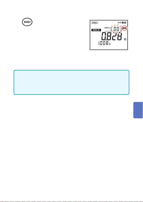
Pressing the MEMO key stores the present measurement values.
Handy function: Auto-memory function (p. 76)
1
2
3
4
Turn on the memory function.
Select the memory number.
After a certain period of time of no
activity, the settings on the display
are conrmed and the instrument
returns to the measurement screen.
When the memory function is on,
you can select the memory number
at any time.
Conrm the settings.
Retain the measurement
values.
When [−−−−] is displayed, the
values cannot be retained.
66
5
Store the measurement
values.
The measurement values are stored
in the cell with the selected memory
number.
After the data is stored, the next
available memory number is
displayed.
The retaining is now canceled.
Storing Data in the Memory
1
2
• Pressing and holding the CLEAR key for 2 or more seconds can clear
the last stored data. However, this operation is possible only immediately
after the data is stored.
• If [USED] is displayed with a memory number, that number will be
overwritten.
3
4
5
6
7
Appx. Index
67
Canceling the Memory Function
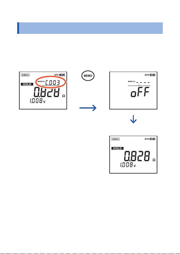
5.3 Canceling the Memory Function
To cancel the memory function when it is on, press and hold the
MEMO key for at least 1 second. [oFF] is displayed, and the
instrument returns to the normal mode.
Memory function: ON Memory function: OFF
(Press and
hold for
at least 1
second.)
Normal mode
68

Reading Out Stored Data
5.4 Reading Out Stored Data
The stored measurement values are displayed after they are read out.
1
2
3
• Press the DATE key to check the date and time when the data
• The comparator result for the data being read out is also
• You cannot select the number of the memory location in which
• If no data has been stored, [−−−−] is displayed in the memory
Display the memory readout
screen.
Select the memory number to
be read out.
The measurement values for the
selected memory number are displayed.
To return to the measurement
screen, press the READ key.
was stored.
displayed.
no data is stored.
number display area and the instrument returns to the
measurement screen.
1
2
3
4
5
6
• For data measured using the optional model 9460 Clip Type Lead
with Temperature Sensor, the temperature is also displayed.
69
7
Appx. Index

Clearing Stored Data
5.5 Clearing Stored Data
Clearing a Single Set of Data
1
2
3
4
Display the memory readout
screen.
Select the number of the
memory cell in which you
want to clear data.
The measurement values for the
selected memory number are
displayed.
Press the key once.
If there is no activity for
approximately 3 seconds, returns to
the readout screen.
Conrm the settings.
The data in the cell with the selected
memory number is now cleared.
70

Clearing Data from Each Unit
Clearing Stored Data
1
2
3
4
Display the memory readout
screen.
Select the unit in which you
want to clear data.
Press the key twice.
1
2
3
If there is no activity for
approximately 3 seconds, returns to
the readout screen.
Conrm the settings.
All data stored in the selected unit
(500 cells) are cleared.
4
5
6
7
Appx. Index
71

Clearing Stored Data
Clearing All Data
1
2
3
Display the memory readout
screen.
Press the key 3 times.
If there is no activity for
approximately 3 seconds, returns to
the readout screen.
Conrm the settings.
All data (12 units/6000 sets) is now
cleared.
72

Other Features
6
6.1 Noise Frequency Avoidance Function
When the noise frequency avoidance function is used, internal
resistance with reduced noise is measured automatically.
Turning the Noise Frequency Avoidance Function ON/OFF
1
2
3
4
Turn off the instrument.
Display the setup screen
for the noise frequency
avoidance function.
Select either [oFF] or [on].
Conrm the settings.
The instrument is restarted.
The settings will not change if
the power is turned off before the
settings are applied.
(when off is selected)
(when on is selected)
1
2
3
4
5
6
7
Appx. Index
: Noise frequency
avoidance function
73

Noise Frequency Avoidance Function
Canceling the Noise Frequency Avoidance Function
The function will be canceled when the power is switched off and
turned on again.
• When the noise frequency avoidance function is turned on, the
time required for measurement may take longer. [FrEq] will
ash.
• It may not be possible to avoid all noise depending on the type
of noise.
74

Auto-hold Function
6.2 Auto-hold Function
This function automatically recognizes the stability of measurement
values and retains them.
Press the A HOLD/MEMO key several times to display [A.HOLD].
1
Auto-hold
OFF
To cancel the retaining, press the HOLD key or the PRESS button
on the model 9466 Remote Control Switch.
• When resistance is displayed as [−−−−], data is not retained
automatically.
• Data will not be retained automatically when [OVER] and the
maximum display value of the resistance are ashing.
• The instrument retains and stores measurement values
automatically when the auto-memory function is used together
with this function.
• Use the auto-hold function together with the comparator
function to determine if [OVER] (and the maximum display
value) is ashing due to a range setting error. Setting the
comparator buzzer to [FAIL] is also recommended. For more
information, see “4.4 Setting the Comparator Buzzer” (p. 63).
Canceling the Auto-hold function
Press the A HOLD/MEMO key several times to hide [A.HOLD].
Auto-memory
Auto-hold and
Auto-memory
2
3
4
5
6
7
Appx. Index
75

Auto-memory Function
6.3 Auto-memory Function
This function automatically stores measurement values in memory
immediately after they are retained.
Press the A HOLD/MEMO key several times to display [A.MEMO].
At this point, the memory function is also turned on.
Auto-hold
OFF
Use the cursor keys to select the memory number of the location
in which the data is to be stored. [USED] is displayed if a memory
number containing data is selected.
• The instrument retains and stores measurement values
automatically when the auto-memory function is used together
with the auto-hold function.
• Use the auto-memory function together with the comparator
function to determine if [OVER] (and the maximum display
value) are ashing due to a range setting error. Setting the
comparator buzzer to [FAIL] is also recommended. For more
information, see “4.4 Setting the Comparator Buzzer” (p. 63).
Auto-memory
Auto-hold and
Auto-memory
Canceling the Auto-memory Function
Press the A HOLD/MEMO key several times to hide [A.MEMO].
76

Auto Power Save Function (APS)
6.4 Auto Power Save Function (APS)
The auto power save function can be used to reduce power
consumption of the instrument. The instrument is turned off
automatically if any of the following conditions continues for
approximately 10 minutes with no key operation:
• [−−−−] is displayed as a resistance value.
• Data is being retained. (Measurement is suspended.)
• A state other than measurement state. (Any of the setup screens
or the data readout screen is displayed.)
• After completion of communication.
[APS] starts ashing 1 minute before the power turns off.
Turning the Auto Power Save function ON/OFF
1
2
Turn off the instrument.
Display the auto power save
setup screen.
1
2
3
4
5
3
4
Select either [oFF] or [on].
Conrm the settings.
The instrument is restarted.
The settings will not change if
the power is turned off before the
settings are applied.
(when on is selected)
6
7
Appx. Index
(when off is selected)
77
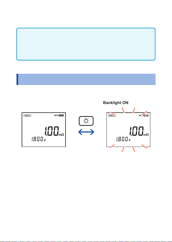
Backlight
• For continuous use of the instrument, set the function to off. (The
default setting is on.)
• When the auto power save setup screen is displayed
unintentionally, turn off the power and turn it on again. The
instrument settings are restored unchanged.
6.5 Backlight
The instrument’s backlight can be turned on and off.
Backlight OFF Backlight ON
78

System Reset
6.6 System Reset
This can be used to restore the instrument to its default settings.
However, note that the following settings will not be cleared:
• Date and time
• Stored measurement data (6000 data sets)
• Comparator threshold values (200 sets)
• Temperature display unit
1
2
3
4
Turn off the instrument.
Display the system reset
screen.
Select [yES].
Select [no] to cancel the system
reset operation.
Conrm the settings.
The instrument is restarted.
1
2
3
4
5
6
7
79
Appx. Index

System Reset
Default Settings (Factory Defaults)
Resistance range 3.000 m
Voltage range 6.000 V
Zero adjustment function Disabled
Auto-hold function OFF
Auto-memory function OFF
Comparator function OFF
Comparator buzzer setting WARNING/FAIL (ON)
Auto Power Save function ON
Temperature display unit °C
Ω
• When the system reset screen is displayed unintentionally, turn
off the power and turn on again. The instrument settings are
restored without resetting the system.
• For more information on how to clear stored measurement
data, see “5.5 Clearing Stored Data” (p. 70).
80

Battery Level Warning
6.7 Battery Level Warning
The battery level of the instrument is displayed at the upper-right
corner of the screen.
1
2
Battery level
indicator
Battery fully charged.
Black charge bars start disappearing from the left as the
battery gets drained.
Battery level is low. Replace the battery as soon as
possible.
(Flashing) Battery is completely drained.
Replace with new batteries.
• Using manganese batteries signicantly reduces the continuous
operating time of the instrument.
• The battery level indicator does not function accurately when
nickel-metal hydride batteries are used.
• The battery level indicator serves as an approximate guideline
for the continuous operating time.
Battery status
81
3
4
5
6
7
Appx. Index

Battery Level Warning
82
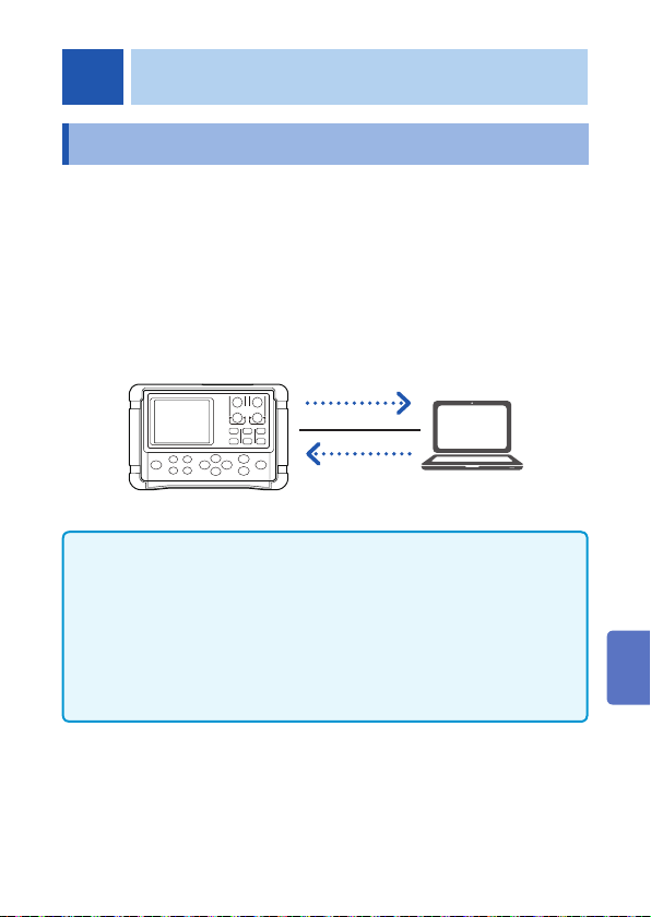
Communications Function
7
7.1 Communicating with a Computer
By using the USB cable included with the instrument, you can send
data to a computer or control the instrument from a computer.
Users can manage the saved data on their smart phones and
tablets. (Only for BT3554-01)
For more information, refer to the manual of the CD shipped with
the instrument.
The virtual COM port on the computer is used as the USB interface.
Send data
Control the
instrument
• Insert the connector in the proper direction when connecting
the USB cable.
• [PC] is displayed on the screen when communication is in
progress through the USB cable.
• Do not disconnect the USB cable when communication is in
progress. The dedicated computer application software displays
a warning message when communication is lost due to cable
disconnection. Connect the disconnected USB cable again.
1
2
3
4
5
6
7
Appx. Index
83
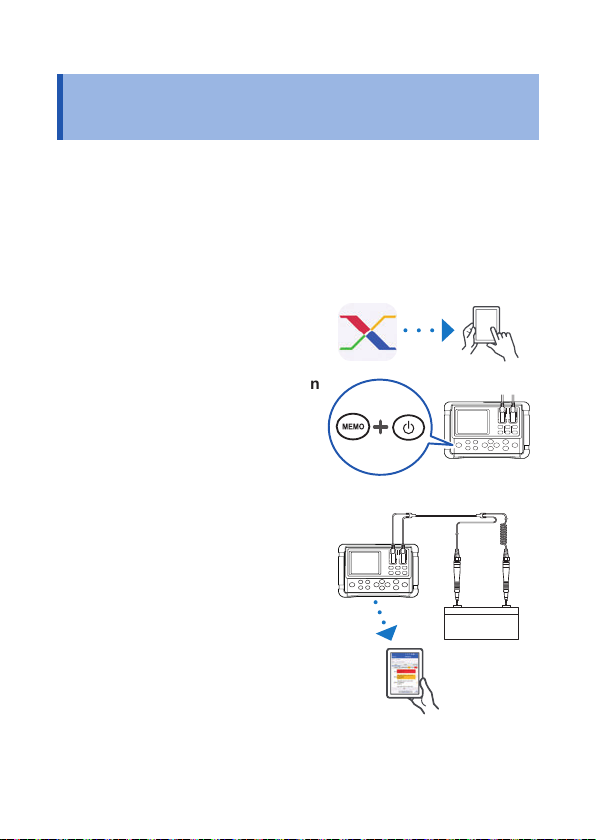
Communicating with a Smart Phone or Tablet (Only for BT3554-01)
7.2 Communicating with a Smart Phone or Tablet (Only for BT3554-01)
The BT3554-01 is a battery tester with Bluetooth® low energy
support. When the Bluetooth® function is enabled, you can review
measurement data and create measurement reports on mobile
devices (iPhone, iPad, iPad miniTM, iPad Pro, iPod touch, and
Android™ devices). For more information about this functionality,
see the help function in the application software GENNECT Cross.
Install the GENNECT Cross on
1
your mobile device. (p. 85)
Enable the Bluetooth® function
2
on the BT3554-01. (p. 86)
Launch the GENNECT Cross
3
and pair it with the BT3554-01.
(p. 87)
Select the general
4
measurement or battery
function. (p. 88)
84

Communicating with a Smart Phone or Tablet (Only for BT3554-01)
Installing the smartphone app GENNECT Cross
Search for “GENNECT Cross” on the App Store from your iPhone,
iPad or other Apple device, or on Google Play™ from your Android
device. Then download and install the GENNECT Cross. You
will need an Apple ID to download the app on the App Store, or a
Google account to download the app on Google Play. For more
information about how to register an account, contact the store at
which you purchased your device.
• Because the BT3554-01 emit radio waves, use in a country
or region where they have not been approved may be
subject to nes or other penalties as a violation of applicable
laws or regulations. For more information, see the attached
“Precautions Concerning Use of Equipment That Emits Radio
Waves” or go to our website.
• BT3554-01 availability is limited to certain countries. For more
information, contact your authorized Hioki distributor or reseller.
• Bluetooth® communications range varies greatly with
distance from obstructions (walls, metal obstruction, etc.) as
well as distance from the oor or ground. To ensure stable
measurement, verify adequate signal strength.
• Although this app is provided free of charge, downloading or
use of the app may incur Internet connection charges. Such
charges are the sole responsibility of the user.
• This app is not guaranteed to operate on all mobile devices.
1
2
3
4
5
6
7
Appx. Index
85

Communicating with a Smart Phone or Tablet (Only for BT3554-01)
Turning ON/OFF the Bluetooth® function
1
2
3
4
is displayed when the Bluetooth® function is on.
ashes when the instrument is connected to a mobile device.
Turn off the instrument.
Display the Bluetooth®
setup screen.
Select [on].
To turn off Bluetooth®, select [oFF].
Conrm the settings.
The instrument is restarted. The
settings will not change if the
power is turned off before the
settings are applied.
(when off is selected)
(when on is selected)
86

Communicating with a Smart Phone or Tablet (Only for BT3554-01)
Pairing the app with the battery tester (BT3554-01)
2
3
1
2
3
1
• When the app is launched for the rst time (before being paired
with any instrument), the connection setup screen will be displayed.
• While the mobile device is displaying the connection setup
screen, simply move it close to the BT3554-01 to automatically
pair it with the instrument (the app can be paired with up to 8
instruments).
• Allow about 5 to 30 seconds for the instrument to pair with the app
after being turned on. If the instrument fails to pair within 1 minute,
relaunch GENNECT Cross and cycle the instrument’s power.
87
4
5
6
7
Appx. Index

Communicating with a Smart Phone or Tablet (Only for BT3554-01)
Making measurements with the Bluetooth® function
Select either the general measurement or battery measurement
function on the home screen and measure. For more information
about each function, see the help function in the GENNECT Cross.
General measurement
function
88
Battery function
(List display function)
Battery function
(Graph display screen)

Specications
8
8.1 General Specications
Operating
environment
Operating
temperature and
humidity
Storage temperature
and humidity
Standards Safety EN 61010
Dielectric strength 1.5 kV AC (cutoff current 5 mA, 1 minute)
Power supply LR6 (AA) alkaline batteries × 8
Continuous
operating time
Backup battery Approx. 10 years (at 23°C)
Interface USB, Bluetooth
Dimensions Approx. 199W × 132H × 60.6D mm
Mass BT3554: Approx. 937 g (33.1 oz.) (including
Product warranty
period
Indoors, Pollution Degree 2, altitude up to 2000 m
(6562 ft.)
Temperature 0°C to 40°C (32°F to 104°F)
Humidity 80% RH or less (no condensation)
Temperature −10°C to 50°C (14°F to 122°F)
Humidity 80% RH or less (no condensation)
EMC EN 61326
Between all measurement terminals and USB
terminal
Rated supply voltage: 1.5 V DC × 8
Nickel-metal hydride batteries can be used.
(However, the battery level indicator is not supported.)
Approx. 8.5 hours (when alkaline batteries are
used, may vary depending on usage conditions)
®
(only for BT3554-01)
(7.83"W × 5.20"H × 2.39"D) (protector attached)
BT3554-01: Approx. 947 g (33.4 oz.) (including
3 years
batteries and protector)
batteries and protector)
1
2
3
4
5
6
7
8
Index
89

General Specications
Fuse 250 V / F 630 mAH (216.630, Littelfuse, Inc.
Accessories p. 2
Options p. 4 to p. 6
Display LCD (monochrome, 182 segments)
product)
90
 Loading...