


Contents
Contents
User's License Agr eem e n t ............. ... .. .. ... ................. .. .. ... .. ....... 1
Introduction ................................................................................1
Operating Precautions ...............................................................2
1 Operating Environment and Installation 3
1.1 Operating Environment ..................................................3
1.2 Installation ......................................................................4
2Overview 7
2.1 Main Functions ...............................................................7
i
2.2 System Configuration Diagram ......................................8
3 Operation (Basics) 11
3.1 Initial Settings for the Measurement System ................11
3.1.1 Starting MAP Editor ........................................................12
3.1.2 Setting the LAN system ..................................................13
3.1.3 Setting the Wireless system ............................................24
3.1.4 Auto Recognition of Measurement Modules ...................42
3.2 Setting the Measurement Para me ters
(Initial settings for the measurement module) ..............44
3.2.1 Common Steps ...............................................................44
3.2.2 Setting Measurement Parameters for
Models 2301 to 2305 ......................................................45
3.2.3 Setting Measurement Parameters for Model 2306 .........47
3.2.4 Setting Measurement Parameters for Model 2321 .........50
3.2.5 Setting Measurement Parameters for Model 2331 .........54
3.2.6 Setting Measurement Parameters for Model 2332 .........56
3.2.7 Setting Measurement Parameters for Model 2341 .........59
3.2.8 Setting Measurement Parameters for Model 2342 .........61
3.2.9 Setting Measurement Parameters for Model 2343 .........66
3.2.10 Common Tab Settings ....................................................76
3.3 Monitorin g Me a surement Value s ..... ................. ............80
3.3.1 Starting and Stopping the Monitor Function ....................81
3.3.2 Displaying a Trend Graph .......................... .... .................83
3.3.3 Setting the Monitor ..........................................................86
3.3.4 Monitoring Screen Right-Click Menu ..............................87
3.4 Checking the Current Waveform ..................................88

ii
Contents
3.5 Recording and A cq uir ing Dat a . .. ... .. ... ..........................91
3.5.1 Starting Data Recording ..................................................91
3.5.2 Acquiring Recorded Data ..............................................103
3.5.3 Stopping Data Recording ..............................................107
3.6 Time Correction ..... .. ... ................................................10 9
3.7 Read the recorded dat a ............. .................................111
3.7.1 Reading the recorded data ...........................................111
3.7.2 Screen Organization of Smart Site Viewer ...................114
3.7.3 Main Functions of "Table" .............................................115
3.7.4 Main Functions of "Graph" ............................................116
3.7.5 Main Functions of "Alarm" .............................................122
3.8 Acquiring Batches of Waveform Data ........................123
3.9 Displaying Waveform Data .........................................124
3.9.1 How to Display Waveform Data ....................................124
3.9.2 Using the Waveform Selection Screen .........................125
3.9.3 Using the Smart Site Wave Viewer ...............................127
3.9.4 Displaying Multiple Waveform Data ..............................130
4 Operation (Advanced) 133
4.1 Creating the Layout ....................................................133
4.1.1 Creating the Layout .......................................................133
4.1.2 Switching layouts ..........................................................150
4.1.3 Right-Click Menus for Layouts and Layout Parts ..........150
4.2 Report Creating Function ...........................................157
4.2.1 Creating a Format File ..................................................158
4.2.2 Confirm output test and format file ................................168
4.2.3 Auto Report Output .......................................................170
4.2.4 Precautions for Report Creation ...................................177
4.3 Calculating Measured Values
(PC Calculation Module) ............................................183
4.3.1 Enabling PC Calculation Modules .................................183
4.3.2 Adding a PC Calculation Module ..................................184
4.3.3 Configuring PC Calculation Modules ............................185
4.4 Initializing the measurement module
before setting up .........................................................188
4.4.1 Setting Measurement Module Configuration and
Measurement Parameters ............................................189
4.4.2 Sending the Measurement Module Settings .................191
4.4.3 Checking the Communication Status ....................... .... .19 2
4.5 Managing Module Lists .............................. ................193
4.6 Other Functions ..........................................................198
4.6.1 Displaying the Communication Status ..........................198
4.6.2 Setting the Administrator Mode .....................................199

Contents
4.6.3 Checking Module Information .......................................201
4.6.4 Acquires all memory data for the measurement module,
and saves it as a CSV file .............................................202
4.6.5 Advanced Communication Settings ..............................204
5 Alarm Function 207
5.1 Overview ....................................................................207
5.2 Function to evaluate alarms by computer ..................208
5.2.1 Alarm operation settings ...............................................208
5.2.2 Start alarm operation ....................................................210
5.2.3 Displaying the Alarm Log ..............................................211
5.2.4 An alarm signal occurs from 2342 Output Module ........213
5.3 Function to evaluate alarms by module ......................217
5.3.1 An alarm data is saved or an alarm signal is
output by the measurement module .............................217
5.3.2 An alarm signal is output by using the
2342 Output Module's evaluation function ....................222
iii
6 Operation (part Model 2354) 235
6.1 Overview ....................................................................235
6.2 Using Off Line .............................................................237
6.2.1 Constructing the System ...............................................239
6.2.2 Saving the Setting to the CF Card ...................... ..... .... .242
6.3 Viewing Recorded Data (O ff line) ...............................245
6.3.1 Converting Recorded Data ...........................................24 5
6.3.2 Viewing Recorded data with Excel ................................250
6.4 Collecting Recorded Data with FTP ...........................252
6.5 Sending Recorded Data Automatically
by the FTP Client ........................................................256
6.6 Time Correction by SNTP Client. ...............................258
6.7 Recording file size for CF card ...................................259
7 Specifications 267
8 9768-01 Server/ Client Option 271
8.1 Install the Server Option software ..............................272
8.2 Install the Client Software Smart Site Client ...............273
8.3 Construct th e M o n i to r ing System ...............................276
8.4 Read record data in multiple computers .....................279

iv
Contents
8.5 Refresh the settings of the module list .......................279
8.6 Refresh the settings (IP address, port number) on the
server computer .........................................................280
8.7 Specifications .............................................................281
9 9768-02 LAN Module Mail Option 283
9.1 Install LAN Module Mail Option ..................................283
9.2 Set conditions for alarm evaluation for
the measurement module ........................ ..................285
9.3 Set alarm notification ..................................................285
9.4 Checking E-mail for Alarm Evaluation Results ...........290
9.5 Setting the Network Alarm Light for
the DN-1000 Serie s .... ................................................291
9.6 Other Important Points ...............................................292
9.7 Specifications .............................................................293
10 9768-03 Modbus server Option 295
10.1 Install the Modbus server option ................................296
10.2 About Modbus address and data format ....................297
10.3 Operate the Modbus server ...................... ..................298
10.4 Notes on Modbus communication ..............................300
10.5 Specifications .............................................................301
Appendix 303
Smart Site Utility Settings Folder Configuration ....................303
Recording folder configuration for Smart Site Utility.............. 304
Number of Wireless Relay Steps .......................................... 305
Wireless Transmission Stages ..............................................306
Cannot Communicate with LAN ............................................307
LAN Terminology .............. .. ...................................................3 0 9
Checking Method for CommunicationPort ...................... .......310
Canceling Standby and Hibernation Functions .....................313
CF card .............. .. ... .. ... ................ ... .. ... .. ................. .. ...3 1 7

User's License Agreement
Important Please read the following agreement ca re ful ly. This user's license agreeme nt
(hereafter referred to as Agreeme nt) is a legal contr act betwe en the software
user (individual or institution) and HIOKI E. E. CORPORATION (hereafter
referred to as HIOKI). The term "software" includes any related electronic
documentation and computer software and media, as well as any printed
matter (such as the Instruction Manual).
By installing, reprodu cing, or using the software, you , the Lic ensee, agr ee to
accept the license terms set forth in this Agreement.
This software is pro tected by copyright laws, international c opyright agreements, as well as non-corporate laws. The software is a licensed product,
and is not sold to the user.
1. License
You may install the software on multiple computers controlled by the same
administrator.
2. Explanation of other rights and restrictions
-1. Restrictions on reverse engineering, decompiling, and disass embling:
You may not reverse engineer, decompile, or disassemble the software.
-2. Separation of components:
This software is li censed for use as a s ingle product. You may not separate
the components for use on multiple computer systems.
-3. Loaning:
You may not loan or lease the software.
-4. Transfer of software:
You may transfer full rights i n accordance with this Agreeme nt. However, if
you do so, you may not retain an y copy of the software, but must transfer the
software in its entirety ( all components, media, related do cumentation such
as the Instruction Manual, and this Agreement), and must ensure that the
receiver of the software agrees with the terms set forth in this Agreement.
-5. Cancellation:
In the event that the terms an d co ndi tio ns se t forth i n thi s Agree men t ar e violated, HIOKI retains the right to cancel this Agreement without compromise of
any of its other rights. In this event, you must destroy all copies of the software and its components.

3. Copyright
The title and copyright r ights concerning the software's related documentation, such as the Instructi on Ma nua l an d cop ie s of the software, are the property of HIOKI and other lic ensors, and are protected by copyright laws an d
international agreem ent re gul ations . A c co rding ly, you must treat the s oftware
as you would any other copyrighted document. However, you are permitted to
make a single co py of the software only if the copy is n ot intended for use
other than back-up purposes.
However, you may not reproduce the docu mentation supplied with the software, such as the Instruction Manual.
4. Dual media software
You may receive the same software on more than one type of media. However, regardless of the type and size of media pro vided, except whe n transferring the software as stipulate d above, you may not loan, leas e, or transfer
the other media to any other user.
5. Warranty
-1. HIOKI reserves the right to make changes to the software specifications without any prior warni ng. If HIO KI releas es a new ve rsion o f the software, i t will
provide registered users with information about the revised software.
-2. If the software do es not operate in accordance with the supplied Instruction
Manual, or the software media or Instruction Manual are damaged in any
way, you have one year from the date of purchase to apply for either an
exchange or repair at HIOKI's discretion.
-3. In no event wil l HIOKI be liable for any damages resu lting from fire, earthquake, or actions of a third party under the conditions stated in item number 2
above, or for any damage caused as a result of your using the software incorrectly or under unusual c ircumstances. Further, the warranty is invalid if the
following occurs:
(A) D amage incu rred throu gh tr ansport, movin g, droppage, or any o ther k ind
of impact after you purchased the software.
(B) D amage incurred through any form of alteratio n, unwarranted servicing,
or any other type of mistreatment.
-4. In the event that the software is exchanged or repaired, the period of warranty
expires on the lates t occurring d ate out of the day stated in the o riginal warranty, and exactly 6 months from the day the exc hange d/repair ed softwar e is
returned to you.
-5. Regar dless of the grounds for ma king a legal claim, HIOKI and its licensors
will not be liable for any damage inc urred (including, but not limited to: lost
profits, suspension of business, loss of data or lost savings) unstated in the
warranty terms for the u se of this s oftware. This is tr ue even if HIOKI is notified of the possibi lit y o f s uch d ama ges . In any e ve nt, HI OKI's li abi li ty s hal l b e
limited only to replacing defective software with software that is not defective.
Introduction
Verifying Package Contents
Safety Symbols
❖
Notation
1
Introduction
Thank you for purchasing the HIOKI “Model 9768 SMART SITE UTILITY PRO.” To
obtain maximum performance from the product, please read this manual first, and keep
it handy for future reference.
When you receiv e the produ ct, inspect i t carefull y to ensure that no damag e occurred
during shipping. If dama ge is evide nt, or if it fails to oper ate accor ding to th e specifi cations, contact your dealer or Hioki representative.
• 9768 SMART SITE UTILITY PRO(CD-R) ................................................................. 1
• Instruction manual..................................................................................................... 1
The following symb ols in this manual ind icate the relative impor tance of cautions and
warnings.
1
2
3
4
Indicates that incorrect operation presents a possibility of
injury to the user or damage to the product.
Other Symbols
Indicates references.
• Unless otherwise specified, “Windows” represents Windows 2000, Windows XP,
Windows Vista, or Windows 7.
• Dialog box represents a Windows dialog box.
• Menus, commands, dialogs, buttons in a dialog, and other names on the screen and
the keys are indicated in brackets.
• Windows and Excel are the registered trademark of Microsoft Corporation in the
United States and/or other countries.
• In this manual, the model number is indicated as follows:
Example: 2351-20 → 2351 (the number following the "-" is omitted.)
5
6
7
8
9
10
11

2
Mouse Operation
Operating Precautions
Click Press and quickly release the left button of the mouse.
Right-click Press and quickly release the right button of the mouse.
Double click Quickly click the left button of the mouse twice.
Drag While holding down the left button of the mouse, move the
Activate Click on a window on the screen to activate that window.
Operating Precautions
Follow these precaut ions to ensu re safe opera tion a nd to ob tain the fu ll ben efits of th e
various functions.
• Always hold the dis c by the edges, so as not to make fingerprin ts on the disc or
scratch the printing.
• Never touch the recorded side of the disc. Do not place the disc directly on anything
hard.
• Do not wet the disc with volatile alcohol or water, as there is a possibility of the label
printing disappearing.
• To write on the disc label surface, use a spirit-based felt pen. Do not use a ball-point
pen or hard-tipped pen, bec ause there is a danger of scratching the surface and
corrupting the data. Do not use adhesive labels.
• Do not expose the disc directly to the sun's rays, or keep it in conditions of high temperature or humidity, as there is a danger of warping, with consequent loss of data.
• To remove dirt, dust, or fingerprints from the disc, wipe with a dry cloth, or use a CD
cleaner. Always wipe radially from the inside to the outside, and do no wipe with circular movements. Never use abrasives or solvent cleaners.
• Hioki shall not be held liable for any problems with a computer system th at arises
from the use of this CD-R, or for any problem related to the purchase of a Hioki
product.
mouse and then release the left button to deposit the chosen
item in the desired position.

1.1 Operating Environment
Computer environment requirements
Operating Environment and
3
Installation 1
1.1 Operating Environment
Hardware CPU: 1 GHz or higher
Memory 512 MB or more
Display Resolution 1024 x 768 dots, 65536 colors or more
Hard disk At least 30 MB of free space
OS: Windows 2000/XP/Vista/7
.NET Framework 2.0
Internet Explorer 5.01 more
(However, when .NET Frame-
work 2.0 is not installed, approximately 500MB alternates are
necessary), plus space for stored data (at least 500 MB recommended)
1
2
3
4
5
6
Interfaces COM port, LAN
7
8
9
10
11
4
1.2 Installation
1.2 Installation
The installation procedure for the 9768 SMART SITE UTILITY PRO is as follows.
Procedure
1. Execute Setup.exe from the English folder on the CD-ROM.
To install the program under Windows 2000/XP, you must be logged in
with Administrator privileges.
Run installation as an administrator.
Installation is carried out in two stages.
• Install NET Framework 2.0
(Only when it is not installed on the computer)
• Install 9768 SMART SITE UTILITY PRO
If Internet Explorer 5.01 or higher is not installed, an error occurs and it cannot be
installed. In that case, install after updating Internet Explorer to the latest version
using software such as Windows Update.
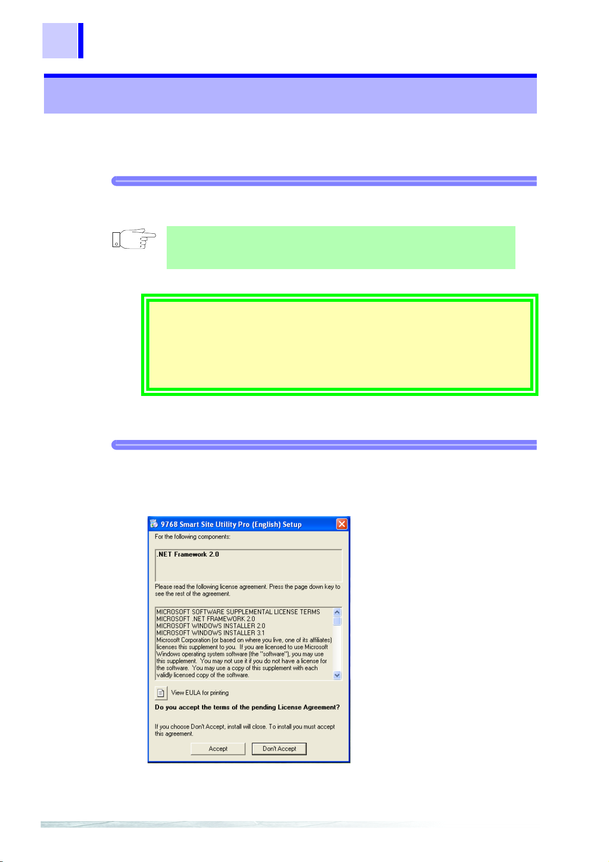
2. If .NET Framework 2.0 is not installed on the computer, the following dia-
log box opens.
❖If .NET Framework 2.0 is already installed, proceed to 6. (P. 6).
3. Click [Accept], .NET Framework 2.0 is installed.
5
1.2 Installation
1
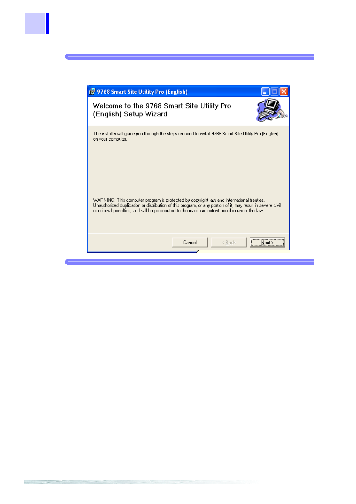
4. When the installation of .NET Framework 2.0 is complete, the 9768
SMART SITE UTILITY PRO installation dialog box opens.
❖Go to 6 (P. 6)
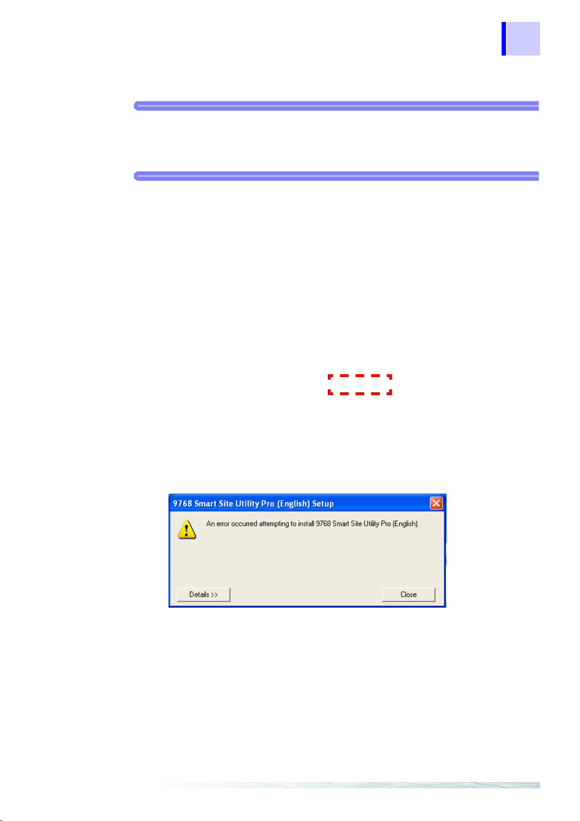
If the following screen opens instead of the 9768 SMART SITE UTILITY P RO installation dialog box, click [Yes] to restart the computer.
After restarting, installation continues automatically.
If the installation is not restarted and the following message appears, execute
Setup.exe again.
When it is executed again, the 9768 SMART SITE UTILITY PRO installation dialog box
opens.
2
3
4
5
6
7
8
9
10
11
6
1.2 Installation
5. Install 9768 SMART SITE UTILITY PRO.
Click [Next] and follow the on-screen instructions to install.
6. When the following screen appears, insta llation is complete.

2.1 Main Functions
Overview 2
2.1 Main Functions
The Smart Site Utility has the following functions.
Make communication settings for communication modules
and measurement parameter settings for measurement modules
Measurement value monitoring
Monitor windows placed on the background screen allow monitoring close to the actual
image.
7
1
2
3
4
Trend graph display
Monitor values can be represented as a trend graph.
Data recording and acquisition
The utility can control the recording function of measurement modules, for periodic
acquisition of data at specified intervals.
Viewing recorded data and alarm data (Smart Site Viewer)
You can view collected recorded data and alarm data as a table or a graph. You can
also print out the graph. Also, table data can be output to Microsoft Excel, and then output as a CSV file.
Create report (Smart Site Viewer)
Using Microsoft Excel, daily and monthly reports can be created, using a format file as
a template.
Alarm
When an alarm is triggered, an alarm log pop-up display and an alarm sound can be
generated.
Operation with a CF card
By using a 2354 Memory Module CF card, this can record operations off line.
Also, data stored on a CF card can be read and viewed by computer card readers or
files downloaded by connecting to FTP.
5
6
7
8
9
10
11

8
2354 MEMORY MODULE
2353 LAN MODULE
Computer
LAN
CAN extension cable
(max. 100 m)
Hub
MODULE ID
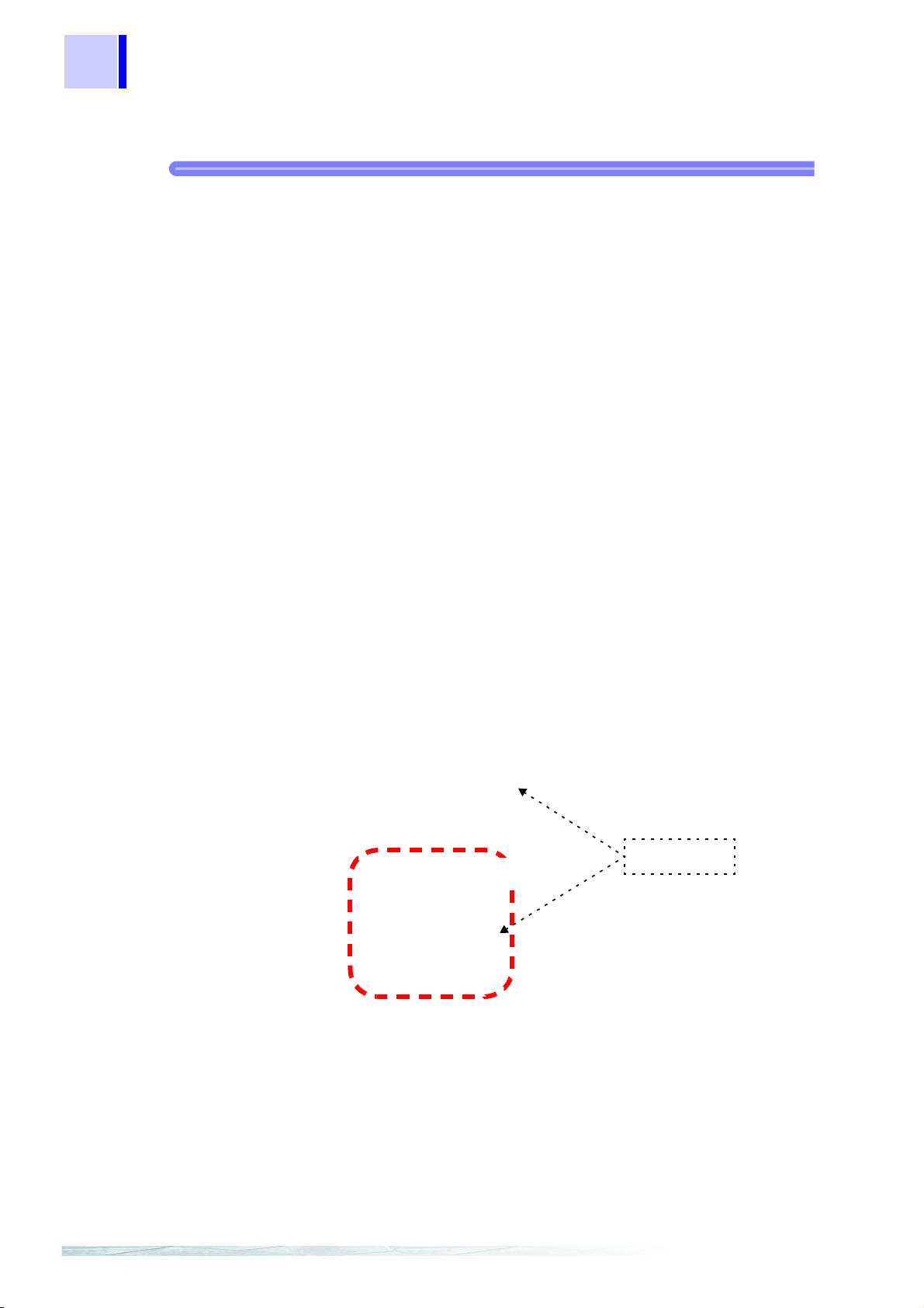
2.2 System Configuration Diagram
2.2 System Configuration Diagram
System example 1......LAN system
❖3.1.2 "Setting the LAN system" (page 13)
COM ID of communication module
• Set within the range 01 to 89.
• In one module list, set a COM ID that is not duplicated.
• If the module list is different, duplicate ID settings are allowed.
MODULE ID of measurement module
• Set within the range 01 to 63.
• Make sure that there are no duplicate MODULE ID settings within the same CAN bus.
• If the communication module is different, duplicate MODULE ID settings are allowed.
*1 Communication module : Collective name for 2351 Air Module, 2352 Wire Module,
2353 LAN Module,2354 Memory Module
*1
*2
*2 Measurement module : Collective name for 2301 Humidity Module to 2305 Instru-
mentation Module, 2306 Multifunction Module, 2331 Power Meter Module, 2332 Power Meter Module, 2341 Input
Module, 2342 Output Module, 2343 RS Link Module

System example 2......Wireless system
Computer
LAN
Hub
2353 LAN MODULE
COM 1
(RS-232C)
2351 AIR MODULE
2351 AIR MODULE
2351 AIR MODULE
2351 AIR MODULE
2351 AIR MODULE
LAN wireless
❖3.1.3 "Setting the Wireless system" (page 24)
9
2.2 System Configuration Diagram
1
2
3
4
When converting LAN wireless, the [2353] LAN MODULE and the [2351] AIR MODULE are connected
within the same CAN bus. Set the [2353] LAN MODULE COM ID to 00.
5
6
7
8
9
10
• Make the ID setting with the rotary switches on the rear of the module.
• When the POWER LED of a module flashes in red, MODULE ID duplication has been detected
within the CAN bus. Change the settings so that all MODULE IDs in the same CAN bus are unique.
• In system con figuratio n diag rams i n this Instr uction Manual , the po wer sour ce and the module base
have been left out.
• If the POWER LE D on e ach m easurin g modu le fla shes ye llow, the sensor may not be conn ected or
no signal has been input. In this status, continue setting the measurement systems.
11

10
2.2 System Configuration Diagram
3.1 Initial Settings for the Measurement System
Operation (Basics) 3
3.1 Initial Settings for the Measurement
11
System
This section describ es the procedur e for makin g only the sett ings that a re required for
communication, and using auto recognition for the measurement modules.
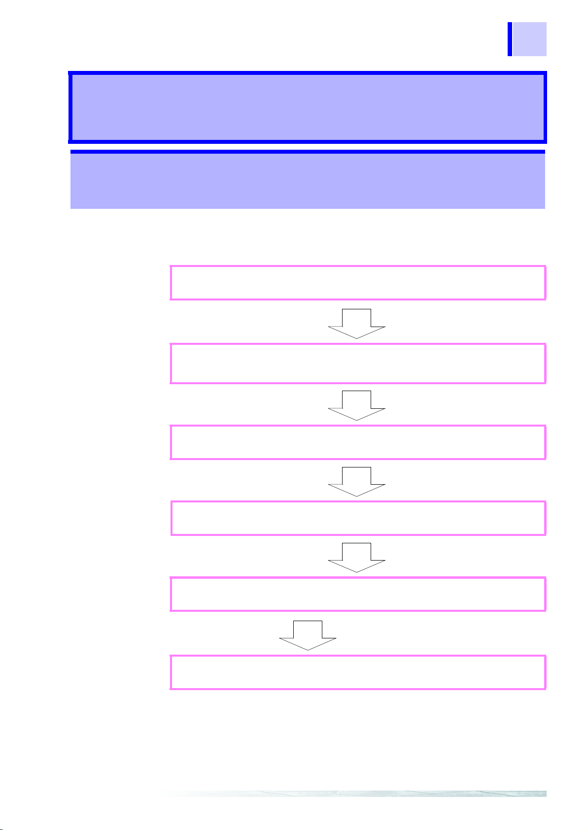
General procedure
1.
2.
3.
Start the MAP editor.
Edit the system you actually want to construct on the MAP editor. Using the
communication modu le only f or editing is fine. At thi s point, ente r the init ial
settings for the communication module.
Each communic ation module is connected to the computer and the initia l
settings are sent.
❖ 3.1.1 (page 12)
2
3
4
5
6
7
4.
5.
6.
Setup the module in the installation position, and construct the system.
Check communication, and measurement modules
installed are automatically recognized.
Set the measurement conditions.
(Initial settings for the measurement module)
❖ 3.1.4 (page 42)
❖ 3.2 (page 44)
8
9
10
11
12
13
12
Serect either
3.1 Initial Settings for the Measurement System
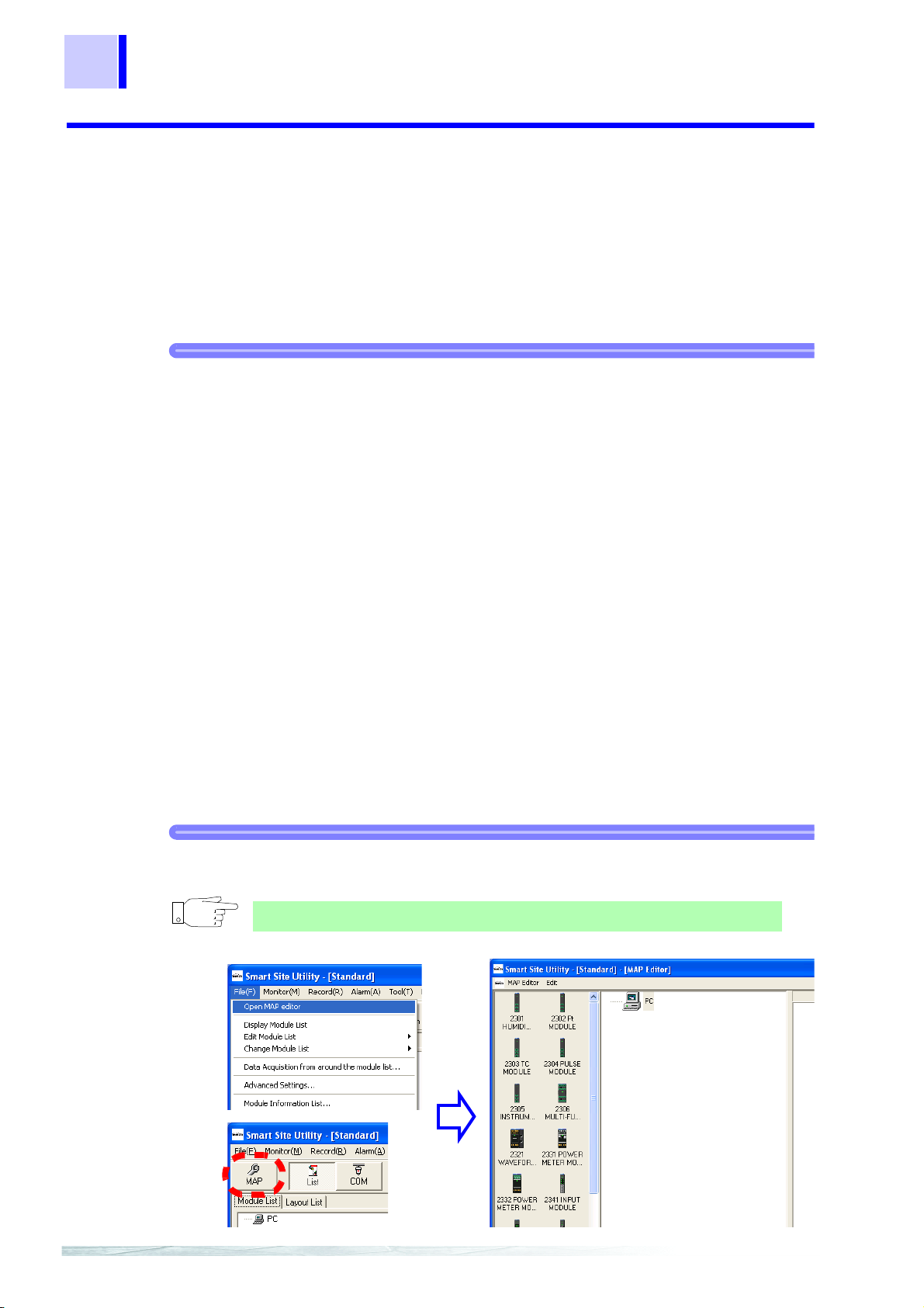
3.1.1 Starting MAP Editor
To use 2300 Smart Site, you need to enter the system configuration (module configuration) into the computer.
To do this, start the Smart Site Utility MAP editor.
• In the MAP ed itor, you can build th e entire modul e con figuratio n inc ludin g measur ement modules.
• For a simple, you enter the intended module configuration into the computer by making settings only for the communication mo dule and using auto reco gnition for the
other modules.
Procedure
1. Start the Smart Site Utility.
Select [Start] - [All Programs] - [HIOKI] - [SmartSite] - [Smart Site Utility].
The illustration below shows an example for st ar ting the Smart Site Utility
in Windows XP.
2. From the menu bar, select [Fil e] - [ Open MAP Editor] to open the MAP editor.
You can also open the MAP editor by selecting [MAP] from the toolbar.
3.1 Initial Settings for the Measurement System
2354 MEMORY MODULE
2353 LAN MODULE
Computer
LAN
Hub
Measurement
module
Computer
LAN
Hub
2353 LAN MODULE
Measurement
module
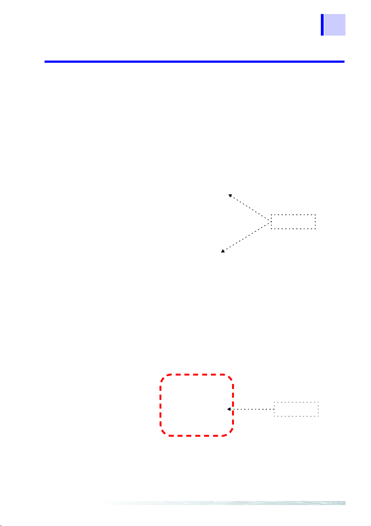
3.1.2 Setting the LAN system
This section describes how to configure a LAN-based system
13
(1) Configuring initial settings for a LAN-based system
This description explains how to set up the following example setup:
2
3
4
5
6
7
[2353] LAN MODULE addition, initial settings
8
9
10
11
12
13
14
Drag and drop here
2.
3.
4.
5.
6.
7.
Procedure
3.1 Initial Settings for the Measurement System
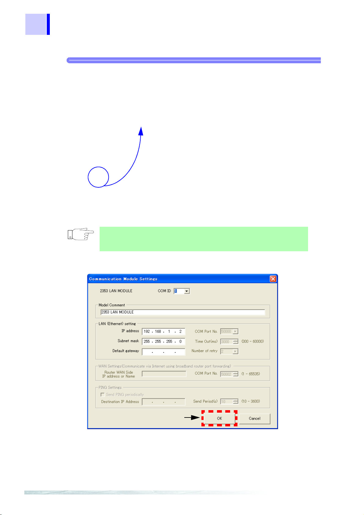
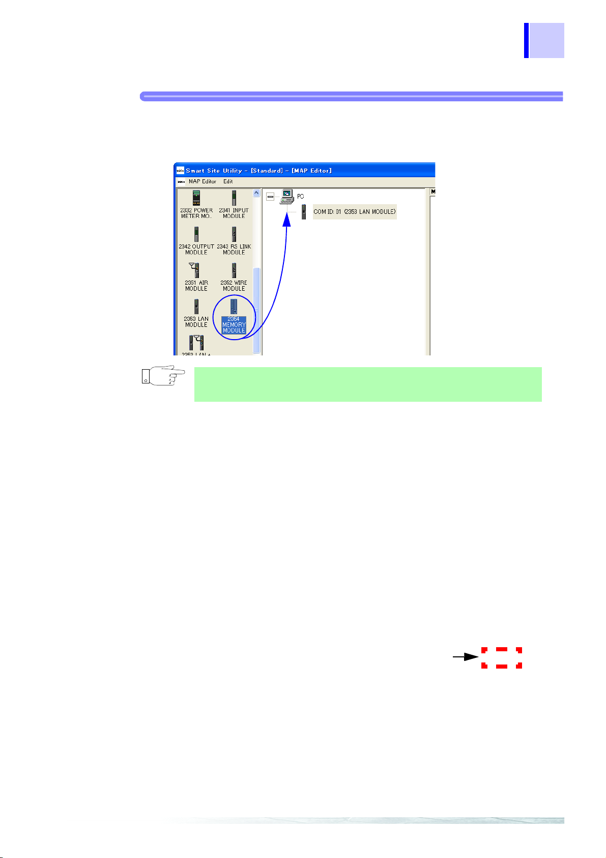
1. Add [2353] LAN MODULE for COM ID:1.
Drag [2353 LAN Module] from the module icon section on the left side of
the screen and drop it onto the [PC] icon in the center.
Right-click on [Computer] to access the popup menu, and then select
[Add] - [2353 LAN MODULE] to make the same settings.
The [Communication module settings] dialog box appears.

15
3.1 Initial Settings for the Measurement System
2. Verify that [COM ID] is set to [1].
• An empty ID is automatically assigned to the COM ID field.
• Any number can be set as long as it does not duplicate other communication modules and IDs.
• Set the rotary switch for the LAN Module to this ID before sending initial
settings.
3. The [Model Comment] field serves for identifying the communication
module to distinguish it from ot her modules . Enter a comment st ri ng here
that is meaningful and easy to understand.
2
3
4
4. In the [LAN (Ethernet) setting] fields, enter the IP address, subnet mask,
and default gateway.
• For information on h ow t o s et thes e ite ms, c ons ul t t he n etwo rk a dmi n-
istrator.
• When no default gateway is used, this field may be left blank.
5. When a LAN module enters an Internet environme nt through a broadb and
router, set [WAN Settings].
A WAN global IP address for a broadband router to which a LAN module
is connected is set to [Router WAN IP address].
[WAN Settings] can be changed when [Advanced Settings] is enabled.
❖4.6.5 "Advanced Communication Settings" (page 204)
5
6
7
8
9
10
6. [PING Send Settings] are set so that a ping is regularly sent to the IP
address specified from the LAN module.
Click from [Send Regular PING], to set the [Dest inat ion I P Address] and
[Send Period(s)].
[PING Send Settings] can be changed when [Advanced Settings] is
enabled.
❖ 4.6.5 "Advanced Communication Settings" (page 204)
11
12
13
16
2353 LAN MODULE
Computer
LAN
Hub
2354 MEMORY MODULE
Measurement
module
3.1 Initial Settings for the Measurement System
7. Click [OK].
The computer and [COM ID:01(2353 LAN Module)] are now connected.
Next [2354] Memory Module is added and initialized.
[2354] Memory Module addition, init ial s e ttings
Procedure
Drag and drop here
2.
3.
4.
5.
6.
7.
8.
11.
9.
10.
17
3.1 Initial Settings for the Measurement System
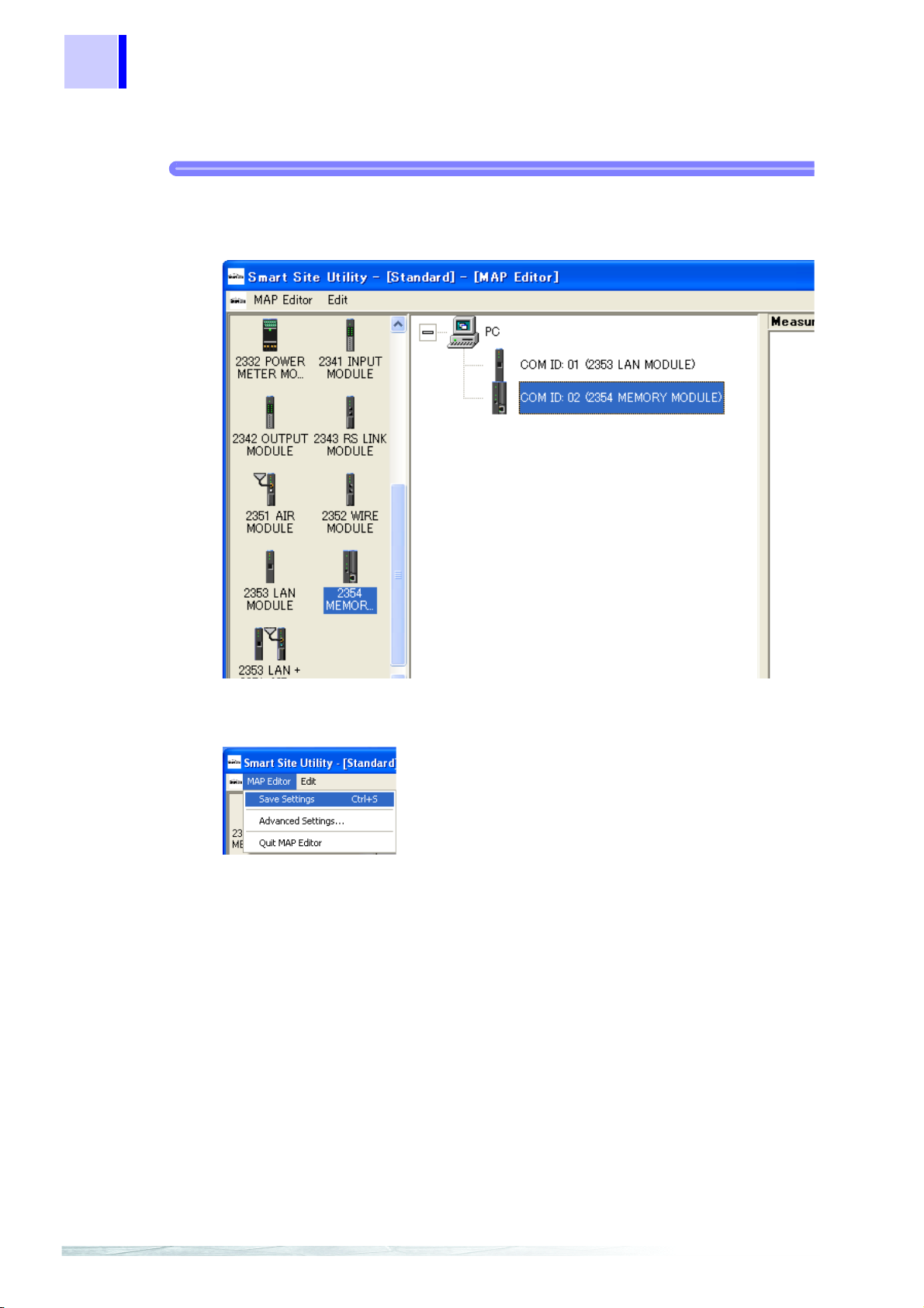
1. Add [2354] Memory Module for COM ID:2.
Drag [2354 Memory Module] from the module icon section on the left side
of the screen and drop it onto the [PC] icon in the center.
2
3
4
Right-click on [Computer] to access the popup menu, and then select
[Add] - [2354 Memory Module] to make the same settings.
The [Communication Module Settings] dialog box appears.
5
6
7
8
9
10
11
12
13

18
3.1 Initial Settings for the Measurement System
2. Verify that [COM ID] is set to [2].
• An empty ID is automatically assigned to the COM ID field.
• Any number can be set as long as it does not duplicate other communication modules and IDs.
• Set the rotary switch for the M emory Module to this ID before s ending
initial settings.
3. The [Model Comment] field serves for identifying the communication
module to distinguish it from other modul es. Enter a comment st ring he re
that is meaningful and easy to understand.
4. In the [LAN (Ethernet) setting] fields, enter the IP address, subnet mask,
and default gateway.
For information on how to set these items, consult the network administrator.
When no default gateway is used, this field may be left blank.
5. When a Memory Module enters an Internet environment through a broad-
band router, set [WAN Settings].
A WAN global IP address for a broadband router to which a Memory Module is connected is set to [Router WAN IP address].
[WAN Settings ] can be changed when [Advanced Settings] is enabled.
❖4.6.5 "Advanced Communication Settings" (page 204)
6. [PING Send Settings] are set so that a ping is regularly sent to the IP
address specified from the Memory Module.
Click from [Send Regular PING], to set the [Destination IP Address] and
[Send Period(s)].
[PING Send Settings] can be changed when [Advanced Settings] is
enabled.
❖4.6.5 "Advanced Communication Settings" (page 204)

19
3.1 Initial Settings for the Measurement System
7. In [Record settings], set the recording method for individual memory
modules.
When [Continue recording] is set from [Operation when insufficient stor-
age space on the CF], old files are deleted one by one when t here is i nsuf-
ficient storage space on the CF card.
When [Stop recording] is set, recording stops but files are not deleted.
When [Create a CSV file] is set from [File format in CF], in addition to the
binary format file, a CSV file for viewing and editing in Excel etc. is created at the same time.
2
3
4
8. In [FTP server settings], set the authentication method for the FTP con-
nection to the memory module.
Click from [Perform user authentication], to set the [User name] and
[Password] when connecting to an FTP.
❖ 6.4 "Collecting Recorded Data with FTP" (page 252)
9. In [FTP client settings], set the function that automatically sends the
recorded data of the memory module to the FTP server once a day.
Click from [Use], to input the [FTP server], [User name], [Password],
[Server store path] and [Transfer time ] and to select the [Active mode] or
[Passive mode].
❖6.5 "Sending Recorded Data Automatically by the FTP Client" (page 256)
10. In [SNTP client settings], set the function that corrects the time of mem-
ory module with NTP server once a day.
Click from [Use], to set the [Time to correct time], [Time difference with
UTC], [NTP server] and [COM port].
❖6.6 "Time Correction by SNTP Client." (page 258)
5
6
7
8
9
10
11
12
13
20
3.1 Initial Settings for the Measurement System
11. Click [OK].
The computer and [COM ID:02(2354 Memory Module)] are now connected.
This completes initial settings on the MAP editor.
Save the settings you created.
Next, the initial settings are sent to each communication module.

3.1 Initial Settings for the Measurement System
仮
(2) Sending LAN system settings
Sending settings to [2353] LAN Module, [2354] Memory Module
Initial settings are sent to [COM ID:01 (2353 LAN Module)] or [COM ID:02 (2354 Mem-
ory Module)]. Send via LAN.
The following is the settin g procedure for the LAN module. Se nd settings to the memory module in the same way.
Procedure
21
1. The COM ID for the LAN Module is set to 01.
(Set with the rotary switch on the rear of the module)
2. Connect the power supply module and 2353 LAN Module to the module
base, and turn power on.
3. Connect the LAN module with the computer by a cross cable or a stra ight
cable via a hub, and then turn on the power to the LAN Module.
2
3
4
5
6
7
4. In the MAP editor, select [COM ID: 01 (2353 LAN Module)] and right-click
to access the popup menu. Then select [Transmit Data Setting to
Modules].
8
9
10
11
12
13

22
6.
3.1 Initial Settings for the Measurement System
5. The following [Transmit Data Setting to Modules].
6. Click the [Send] button to ini tiate the transmission.
7. When the settings have been sent, the message [Settings sent.] appears.
Ver ify that the procedur e was successf ul, and cl ick the [ OK]- [ End] button
to close the dialog box.
When the settings are sent, the internal clock of the module
will be set to the same time as the clock of the computer.
Note
When the IP address for the network address set in the LAN module and for each
computer (network group) is different, the following dialog box opens.
This means that after succe ssfully setting the IP address fo r the LAN module, a
communication test was carried out b etween the com puter and the L AN module,
but communication was not possible because the network group is different.
The LAN module settings are successfully completed.
 Loading...