

9695-80
クランプオンセンサ
CLAMP ON SENSOR
取扱説明書 / Instruction Manual
2012 年 9月 改訂 5 版 Printed in Japan
9695D980-05 12-09H
9695-80
仕様
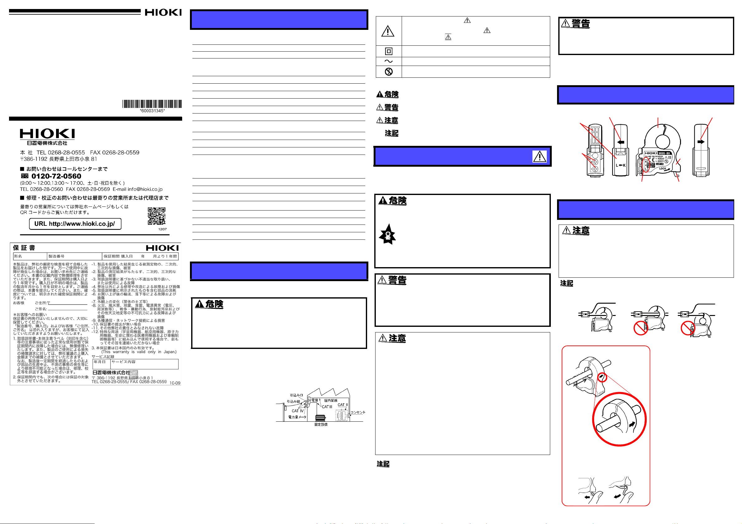
出力端子
電流方向マーク
電流方向マーク
クランプコア
ケーブル極性表示
レバー
ロックつまみ
出力端子
カバー
出力端子カバー
開いた状態
OK
1. 測定器の電源が OFFになってい
るか確認します。
2. 端子カバーを開き、各端子の極
性を合わせてケーブルを 969580 本体の接続端子に接続しま
す。
3. ケーブルを測定器の入力端子に
接続します。
4. 測定器の電源を ON にします。
5. レバーがロックされている場合
は、ロックを解除します。
6. クランプ部を開きます。電流方
向マークの矢印を負荷側に向け
て、導体を 1 本だけ中央にクラ
ンプします。
7. クランプコアを閉じ、ロックし
ます。
ばねがありませんので、必ず
ロックしてください。
電源側
電線
負荷側
L
O
A
D
S
O
U
R
C
E
クランプする
電流方向マークを負荷側へ向ける
(向きを反対にすると、位相が 180°ずれ
てしまいます)
電流方向マーク
ロックの解除
1
2
(確度は
回まで )
定格一次電流
定格二次電流
振幅確度
位相確度
振幅周波数特性
導体位置の影響
外部磁界の影響
最大入力電流
耐電圧
対地間最大定格
電圧
使用温湿度範囲
保存温湿度範囲
使用場所
適合規格
測定可能導体径
出力端子
ケーブル長
外形寸法
質量
付属品 取扱説明書
オプション
製品保証期間
f.s.: 最大表示値、目盛長 ( 一般的には、現在使用中のレンジを表します )
rdg.: 読み値 ( 現在測定中の値、測定器が現在指示している値を表します )
2
3°C±5°C, 80%rh 以下において 1 年間保証、センサ部開閉回数 10000
AC100 A
AC100 mA
±0.5% rd g .±0.2% f.s. (f.s.は3166, 3168
組み合わせたときの確度は各本体の仕様を参照
45Hz
~
66Hz,
コア中心にて
±1°
以内(45 Hz ~ 5 kHz)
±1% 以内(40 Hz~ 5 kHz, 確度からの偏差)
±0.5% 以内(中心からの偏差)
0.1 A 相当以下(400 A/m の交流磁界において)
130 A 連続(45 ~ 66 Hz,周囲温度 50
AC3536 Vrms 15
AC300 Vrms 以下(絶縁導体)
°C
0 ~ 50
-10 ~ 60
高度 2000 m 以下 , 屋内
(
安全性
) EN61010
(EMC) EN61326
φ15 mm 以下
M3 端子台(JIS 規格 RAV1.25-3)
3 m 以下(ツイスト線)
約 50.5W
約 50 g
9219 接続ケーブル
1 年
(予想される過渡過電圧
秒間(電気回路-コア間)
, 80%rh 以下 (結露しないこと )
°C
, 80%rh 以下(結露しないこと)
測定カテゴリ
×58.0H × 18.7D mm (突起物含まず)
III,
)
汚染度
の各レンジとする
°C
)
2
4000 V
)
,
安全について
安全記号
使用者は、取扱説明書内の マ-クのあるところは、必ず読み
注意する必要があることを示します。
使用者は、機器上に表示されている
て、取扱説明書の
してください。
二重絶縁または強化絶縁で保護されている機器を示します。
交流
,
取扱説明書の注意事項には、重要度に応じて以下の表記がされています。
(AC)
絶縁保護具(電気用ゴム手袋、電気用ゴム長靴、安全帽等)を着
用して、活線状態の電路に着脱できることを示します。
操作や取扱いを誤ると、使用者が死亡または重傷につながる危険
性が極めて高いことを意味します。
操作や取扱いを誤ると、使用者が死亡または重傷につながる可能
性があることを意味します。
操作や取扱いを誤ると、使用者が傷害を負う場合、または機器を
損傷する可能性があることを意味します。
製品性能および操作上でのアドバイス的なことを意味します。
使用上の注意
この取扱説明書には本器を安全に操作し、安全な状態に保つのに要する情報や
注意事項が記載されています。本器を使用する前に下記の安全に関する事項を
よくお読みください。
を示します。
マ-クの該当箇所を参照し、機器の操作を
• 短絡事故や人身事故を避けるため、本器は AC300 V 以下
マ-クのところについ
使用前の確認
金属が露出していないか、使用する前に確認してください。損傷があ
る場合は、感電事故になるので、お買上店 ( 代理店 )か最寄りの営業
所にご連絡ください。
使用前には、保存や輸送による故障がないか、点検と動作確認をしてから使用
してください。故障を確認した場合は、お買上店 ( 代理店 ) か最寄りの営業所
にご連絡ください。
各部の名称
測定方法
の電路で使用してください。また裸導体には使用しない
でください。
• 本器は、必ずブレーカの二次側に接続してください。ブ
レーカの二次側は、万一短絡があっても、ブレーカにて
保護します。一次側は、電流容量が大きく、万一短絡事
故が発生した場合、損傷が大きくなるので、測定しない
でください。
• 測定器の電源が入った状態、または測定導体をクランプした状態
で、ケーブルの付け外しをしないでください。本体およびセンサ
の故障の原因になります。
• 9695-80 本体端子部のねじを紛失した場合、「ばね座組込みねじ
M3 × 5」をお求めください。それ以外のねじを使用すると、本器
の破損の原因となります。
はじめに
このたびは、HIOKI 9695-80 クランプオンセンサ をご選定いただき、誠にありが
とうございます。この製品を十分にご活用いただき、末長くご使用いただくため
にも、取扱説明書はていねいに扱い、いつも手元に置いてご使用ください。
概要
本器は 100 A 定格の交流電流対応の電流出力型クランプオンセンサです。
本器は電力ラインを切り離すことなく、活線状態で交流電流の測定ができま
す。また、操作も簡単なため、多方面での電流、電力測定にご使用いただけます。
点検
本器がお手元に届きましたら、輸送中において異常または破損がないか点検し
てからご使用ください。万一、破損あるいは仕様どおり動作しない場合は、お
買上店 ( 代理店 ) か最寄りの営業所にご連絡ください。
保守・サ-ビス
• 本器の汚れをとるときは、柔らかい布に水か中性洗剤を少量含ませて、軽く
ふいてください。ベンジン、アルコ-ル、アセトン、エ-テル、ケトン、シ
ンナ-、ガソリン系を含む洗剤は絶対に使用しないでください。変形変色す
ることがあります。
• 故障と思われるときは、
い。輸送中に破損しないように梱包し、故障内容も書き添えてください。
輸送中の破損については保証しかねます。
お買上店(代理店)
か最寄りの営業所にご連絡くださ
本器を安全にご使用いただくために、また機能を十二分に活用いただくため
に、下記の注意事項をお守りください。
この機器は IEC 61010 安全規格に従って、設計され、試験し、安全
な状態で出荷されています。測定方法を間違えると人身事故や機器
の故障につながる可能性があります。取扱説明書を熟読し、十分に
内容を理解してから操作してください。万一事故があっても、弊社
製品が原因である場合以外は責任を負いかねます。
測定カテゴリについて
本器の測定対象電路は CAT III です。
測定器を安全に使用するため、IEC61010では測定カテゴリとして、使用する
場所により安全レベルの基準を CAT Ⅱ~ CAT Ⅳで分類しています。
CAT II : コンセントに接続する電源
コード付き機器(可搬形工
具・家庭用電気製品など)の
一次側電路
コンセント差込口を直接測
定する場合は CAT Ⅱです。
CA T III:
直接分電盤から電気を取り
込む機器(固定設備)の一
次側および分電盤からコン
セントまでの電路
CAT IV :
建造物への引込み電路、引込み口から電力量メータおよび一次側電流
保護装置(分電盤)までの電路
カテゴリの数値の小さいクラスの測定器で、数値の大きいクラスに該当する場
所を測定すると重大な事故につながる恐れがありますので、絶対に避けてくだ
さい。
カテゴリのない測定器で、CAT Ⅱ~ CAT Ⅳの測定カテゴリを測定すると重大
な事故につながる恐れがありますので、絶対に避けてください。
• 本器をぬらしたり、ぬれた手で測定しないでください。
感電事故の原因になります。
• 活線で測定するので、感電事故を防ぐため、労働安全衛生規則に定
められているように、電気用ゴム手袋、電気用ゴム長靴、安全帽等
の絶縁保護具を着用してください。
• 測定範囲を超える電流を長時間入力しないでください。本器を破
損する恐れがあります。
• 直射日光や高温、多湿、結露するような環境下での、保存や使用
はしないでください。変形、絶縁劣化を起こし、仕様を満足しな
くなります。
• クランプを落下させたり、衝撃を加えないでください。コアの突
合わせ面が損傷し、測定に悪影響を及ぼします。
• クランプコア先端部に異物等を挟んだり、コアの隙間に物を差し
込んだりしないでください。センサ特性の悪化、開閉動作不具合
の原因になります。
• 使用しないときは、クランプコアを閉じておいてください。開い
たままの状態にしておくと、コアの突き合わせ部にゴミやホコリ
が付着し、故障の原因になります。
• 出力端子ネジは強く締めすぎないでください。0.5N
•m 程度が適切
です。
• トランスや大電流路など強磁界の発生している近く、また無線機など強電界
の発生している近くでは、正確な測定ができない場合があります。
• 出力端子にケーブルを接続する場合、外部磁界の影響を抑えるため、できる
だけ端子近くまでケーブルをよってください。
• HIOKI クランプ電力計へ接続の場合は、専用の 9219 接続ケーブルを使用し
てください。(9219の接続部は「圧着端子- BNC」となっています)
導体は必ず 1 本だけクランプしてください。単相(2 本)、三相(3 本)を同時
にクランプした場合は測定できません。
Introduction
The Declaration of Conformity for instruments that comply to CE
mark requirements may be downloaded from the HIOKI website.
9695-80
CLAMP ON SENSOR
Instruction Manual
September 2012 Revised edition 5 Printed in Japan
9695D980-05 12-09H
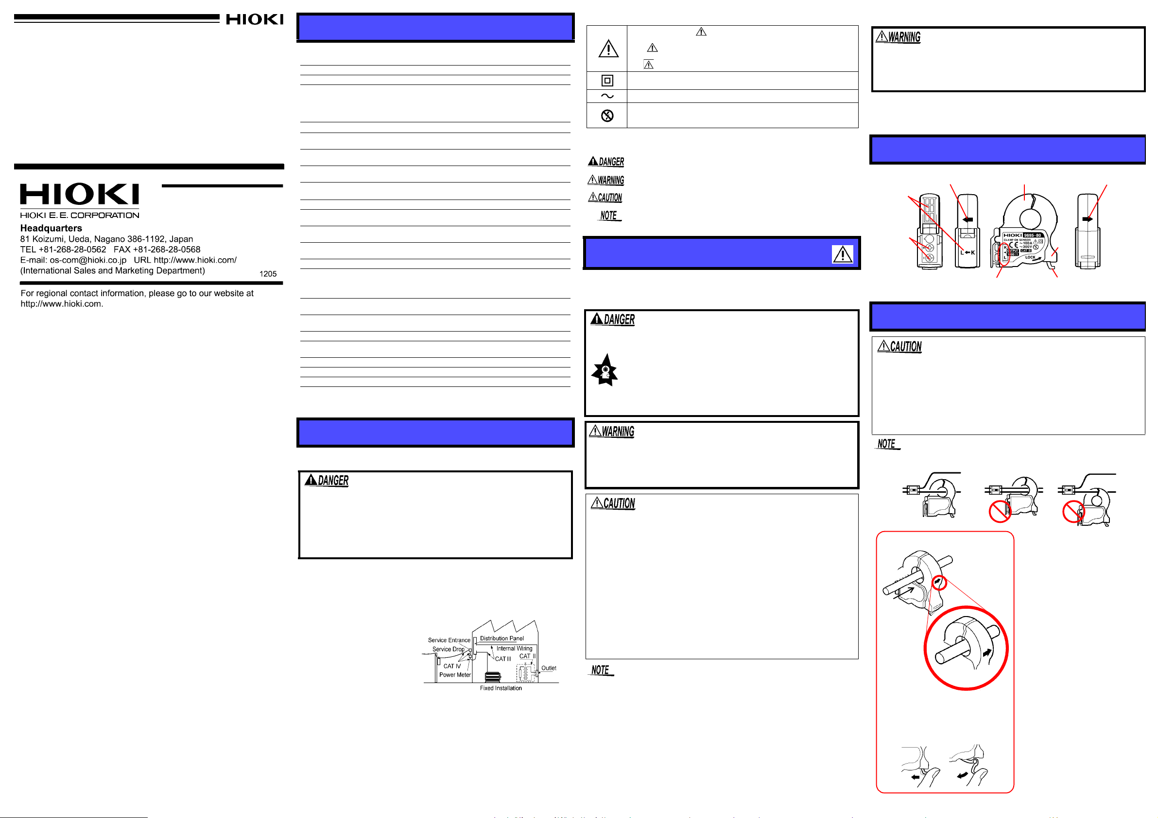
Current direction indicator
Current direction indicator
Clamp jaws
Lever
Lock knob
Cable polarity display
Output
terminal
cover
Output
terminals
OK
1. Confirm that the tester connected to the clamp-on sensor is powered off.
2. Open the terminal cover and
connect the cable to the terminal of the 9695-80. Make
sure that the polarities
match.
3. Connect the cable to the
input terminal of the tester.
4. Turn on the tester.
5. If the lever is locked, unlock
it.
6. Open the clamp core. Orient
the current di rec tio n indi cat or
to the load side and clamp
one conductor at the center
of the clamp core.
7. Close the clamp core and
lock it. Be sure to lock the
clamp core since it has no
spring.
L
O
A
D
S
O
U
R
C
E
Position the clamp with the current
direction indicator pointing toward the
load side. (If installed in the opposite
direction,the phase deviates 180
degrees.)
Current direction
indicator
Clamp the conductor.
Electric
conductor
Unlock the lever
1
2
Thank you for purchasing the HIOKI 9695-80 CLAMP ON SENSOR.
To obtain maximum performance from the product, please read this
manual first, and keep it handy for future reference
Overview
The 9695-80 are current-output, clamp-on sensors used for 100 A
rated AC measurement.
The 9695-80 sensors are designed to measure alt erna tin g cu rrents on
a hot conductor without di sconn ectin g it from the power line. Both se nsors are easy to operate and suitable for electric current and power
measurement in various fields.
Initial Inspection
When you receive the product, inspect it carefully to ensure that no
damage occurred during shipping. If damage is evident, or if it fails to
operate according to the specifications, contact your dealer or Hioki
representative.
Maintenance and Service
• To clean the product, wipe it gently with a soft cloth moistened with
water or mild detergent. Never use solvents such as benzene, alcohol, acetone, ether, ketones, thinners or gasoline, as they can
deform and discolor the case.
• If the product seems to be malfunctioning, contact your dealer or
Hioki repre sentat ive. Pack t he prod uct ca refull y so th at it will no t be
damaged during ship me nt, an d inc lu de a de tailed written descriptio n
of the problem. Hioki cannot be responsible for damage that occurs
during shipment.
Specifications
(Accuracy guaranteed for one year at 23°C±5°C(73°F±9°F), 80%RH or less.
Endurance number of the core opening and closing part: 10000 times)
Rated primary current 100 A AC
Rated secondary current 100 mA AC
±
0.5% rdg.±0.2%f.s. (45Hz to 66Hz, at core center,
Amplitude accuracy
Phase accuracy
Amplitude frequency
characteristics
Effect of conductor
position
Effect of external
electromagnetic field
Maximum input current
Dielectric strength
Maximum rated voltage to
earth
Operating Temperature
&Humidity
Storage Temperature
&Humidity
Operating Environment
Standards applying
Measurable conductor
diameter
Output terminals
Cable length 3 m or less
Dimensions
Mass Approx. 50 g (1.8 oz.)
Accessory
Option
f.s. : maximum display value or scale length
rdg.: reading value (The value currently being measured and indicated on the
measuring product)
Note that f.s. is the range of the 3166 and 3168 CLAMP ON
POWER HiTESTER units. Please refer to the HiTESTER specifications to ensure accuracy when using this unit with a Power
HiTESTER unit.)
Within
±
1° (45 Hz to 5 kHz)
Within ±1% at 40 Hz to 5 kHz (deviation from accuracy)
Within ±0.5% (deviation from center)
0.1 A equivalent or lower
(in an AC electromagnetic field of 400 A/m)
130 A continuous
(at 45 to 66 Hz, ambient temperature 50
3536
V ACrms for 15 sec (between electric circuit and core)
300 V ACrms or lower (Insulated conductor)
°C (32 to 122°F)
0 to 50
(non-condensating)
°C(14 to 140°F)
-10 to 60
(non-condensating)
Indoors, up to 2000 m (6562-ft.) ASL
Safety
EMC EN61326
15 mm (0.59”) or less
M3 terminal (Maximum outside diameter: 6.5 mm/0.26”, inside
diameter: 3.2 mm/0.13”)
Approx. 50.5W x 58.0H x 18.7D mm (1.99”W x 2.28”H x
0.74”D) (excluding protrusions)
Instruction Manual
9219 CONNECTION CABLE
EN61010
Measurement Category III, Polluti on Degree 2
(Anticipated Transient Overvoltage: 4000 V)
, 80%RH or lower
, 80%RH or lower
°
C
)
Safety
Follow these precautions to ensure safe operation and to obtain the
full benefits of the various functions.
This product is designed to conform to IEC 61010 Safety Standards, and has been thoroughly tested for safety prior to shipment. However , misha ndling during use could resul t in injury or
death, as well as damage to the product. Be certain that you
understand the instructions and precautions in the manual
before use. We disclaim any responsib ility for accid ent s or injuries not resulting directly from product defects.
Measurement categories
This product conforms to the safety requirements for CAT III measurement
products.
To ensure safe operation of measurement products, IEC 61010 establishes
safety standards for various electrical environments, categorized as CAT II to
CAT IV, and called measurement categories.
CAT II: Primary electrical circuits
in equipment connected to an AC
electrical outlet by a power cord
(portable tools, household appliances, etc.)
CAT II covers directly measuring
electrical outlet receptacles.
CAT III: Primary electrical circuits of heavy equipment (fixed
installations) connected directly
to the distribution panel, and
feeders from the distribution panel to outlets.
CAT IV: The circuit from the service drop to the service entrance, and to the
power meter and primary overcurrent protection device (distribution panel).
Using a measurement product in an environment designated with a highernumbered category than that for which the product is rated could result in a
severe accident, and must be carefully avoided.
Use of a measurement instrument that is not CAT-rated in CAT II to CAT IV
measurement applications could result in a severe accident, and must be carefully avoided.
Safety Symbol
In the manual, the symbol indicates particularly important
information that the user should read before using the product.
The symbol printed on the product indicates that the user
should refer to a corresponding topic in the manual (marked with
the symbol) before using the relevant function.
Indicates a double-insulated device.
Indicates AC (Alternating Current).
Wear appropriate protective insulation (insulating rubber gloves
and boots, helmet and etc.) when connecting and disconnecting
from live electric circuits.
The following symbols in this manual indicate the relative importance
of cautio ns and warnings.
Indicates that incorrect operation presents an extreme hazard that
could result in serious injury or death to the user.
Indicates that incorrect operation presents a significant hazard that
could result in serious injury or death to the user.
Indicates that incorrect operation presents a possibility of injury to
the user or damage to the product.
Advisory items related to performance or correct operation of the
product.
Usage Notes
This manual contains information and warnings essential for safe
operation of the product and for maintaining it in safe operating condition. Before using the product, be sure to carefully read the following
safety notes.
• To avoid short circuits and potentially life-threatening
hazards, never attach the product to a circuit that operates at more than the 300 V, or over bare conductors.
• This product should only be connected to the secondary side of a breaker, so the breaker can prevent
an accident if a short circuit occurs. Connections
should never be made to the primary side of a
breaker, because unrestricted current flow could
cause a serious accident if a short circuit occurs.
• To avoid electric shock, do not allow the product to get wet,
and do not use it when your hands are wet.
• To avoid electric sho ck when measuri ng live lines, wear app ropriate protective gear, such as insulated rubber gloves, boots
and a safety helmet.
• Note that the product may be damaged if the applied current exceeds the measurement range.
• Do not store or use the product w here it could be ex posed to dire ct
sunlight, high temperature or humidity, or condensation. Under
such conditions, the product may be damaged and insulation may
deteriorate so that it no longer meets specifications.
• Be careful to avoid dropping the clamps or otherwise subjecting
them to mechanical s hock, whi ch could damage th e mating surfa ces of the core and adversely affect measurement.
• Keep the clamp jaws and core slits free from foreign obje cts , which
could interfere with clamping action.
• Keep the clamp closed when not in use , to avoid accumulati ng dust
or dirt on the mating core surfaces, which could int erfere with clamp
performance.
• Do not fix the output terminal screws too tightly. The torque about
•m is recommended.
0.5N
• Accurate me asu rem en t may be im po ss ibl e in the pre se nce of stro ng
magnetic fields, s uc h as nea r tra ns form ers an d h igh -cu rrent conductors, or in the presence of stro ng e lectromag netic fields s uch as near
radio transmitters.
• When connecting the cables to the output terminal, twist the cables
together as close to the termina l as poss ible to av oid the in fluenc e of
an external magnetic field
• Use the 9219 CONNECTION CABLE to connect this product to the
HIOKI clamp wattmeter. (The connector of the 9219 is a solderless
terminal to BNC.)
Preliminary Checks
Before using the product, make sure that no bare conductors
are improperly exposed. Using the product in such conditions
could cause an electric shock, so contact your dealer or Hioki
representative for repair.
Before using the product the first time, verify that it operates normally
to ensure that the no damage occurred during storage or shipping. If
you find any damage, contact your dealer or Hioki representative.
Parts Names
When output cover
is opened
Measurement Procedures
• Do not disconnect the cable when the tester connected to the
clamp-on sensor is on or with the sensor clamped on a conductor
to measure. This prevents the 9695-80 main unit and sensor from
malfunctioning.
• M3x5 screws and a spring washer assembly should be us ed for the
9695-80 terminals. When using another type of screw (especially
longer ones), be careful with the tightening torque. Tightening a
screw too much may damage the 9695-80.
Attach the clamp around only one conductor. Single-phase (2-wire) or
three-phase (3-wir e) cabl es cla mped togethe r will not prod uce an y readi ng.
 Loading...