

Introduction
9691,9692,9693
CLAMP ON AC/DC SENSOR
Instruction Manual
November 2008 Revised edition 6 Printed in Japan
9691A981-06 08-11H
OK
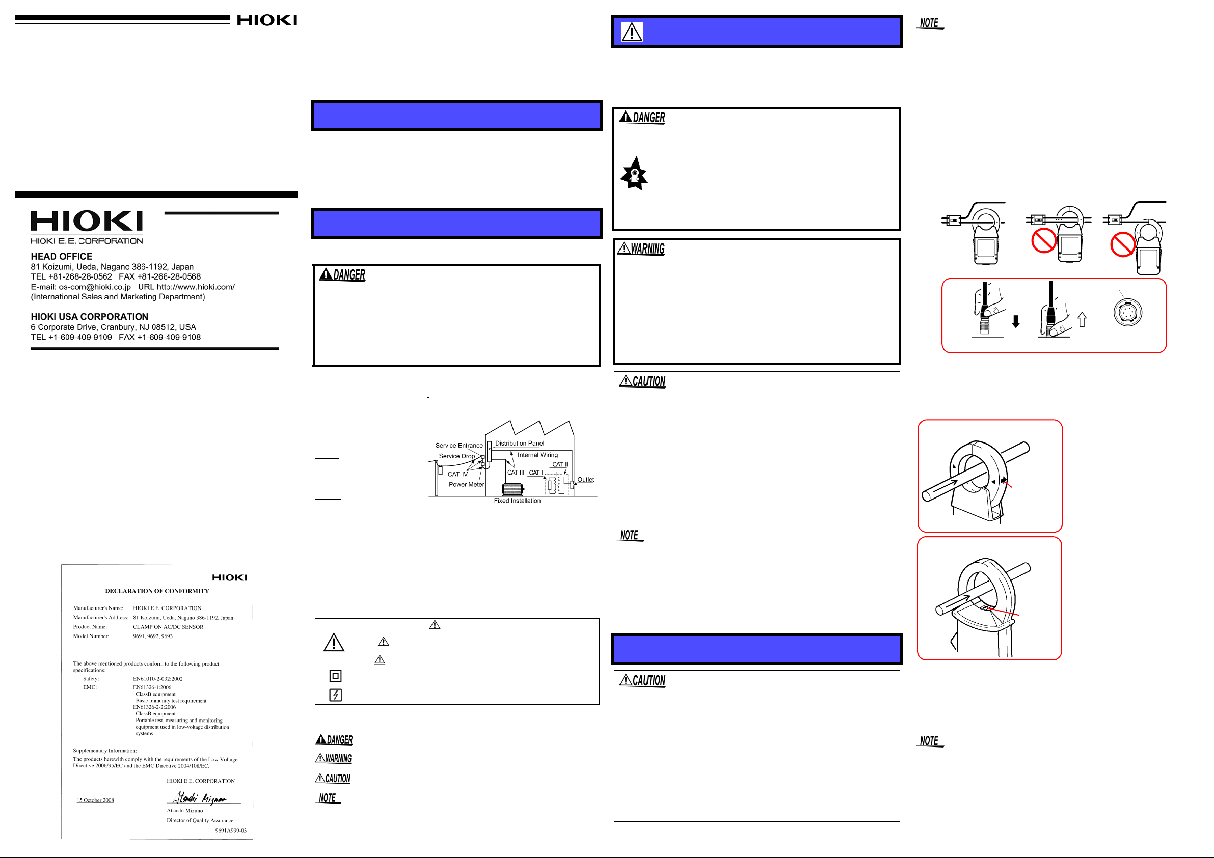
Connecting
Disconnecting
Output connector
Wide terminal
1. Confirm that power of the 3290
is OFF.
2. Connect the output connecto r of
the sensor to the sensor
connector of the 3290.
3. Press the POWER key of the
3290 to turn it ON.
4. Open the ends of the clamp
core. Orient the current
direction indicator on the sensor
in the current direction of the
conductor to be measured, then
clamp the conductor so that it
passes through the center of
the clamp core. (For DC
measurement, perform zero
adjustment on the 3290 before
clamping a conductor with the
clamp sensor. For AC
measurement, note that the
current direction indicator need
not be oriented in the current
direction.)
5. The 9691 has a lock
mechanism on its rear panel
side to prevent the sensor from
opening during measurement.
To prevent the sensor from
possibly being opened due to
vibration or other similar
causes, be sure to lock it before
starting measurement. (Even if
the sensor opens slightly during
measurement, the
measurement value will be less
and accuracy cannot be
guaranteed.)
Power
source
Measured
conductor
Load
9691 CLAMP ON AC/DC SENSOR
Power
source
Measured
conductor
Load
9692,9693 CLAMP ON AC/DC SENSOR
Current
direction
indicator
Current
direction
indicator
Thank you for purchasing the HIOKI “9691, 9692, 9693 CLAMP ON
AC/DC SENSOR.” To obtain maximum performance from the product,
please read this manual first, and keep it handy for future reference
Initial Inspection
When you receive the product, inspect it carefully to ensure that no
damage occurred during shipping. If damage is evident, or if it fails to
operate according to the specifications, contact your dealer or Hioki
representative.
Preliminary Checks
• Before using the product the first time, verify that it operates normally to ensure tha t th e n o d am age oc curred during storage or shipping. If you find any damage, contact your dealer or Hioki
representative.
• Before using the product, make sure that the insulation on the
cables is undamaged and that no bare conductors are improperly
exposed. Using the product in such conditions could ca us e an electric shock, so contact your dealer or Hioki representative for
repair.
Maintenance and Service
• To clean the product, wipe it gently with a soft cloth moistened with
water or mild detergent. Never use solvents such as benzene, alcohol, acetone, ether, ketones, thinners or gasoline, as they can
deform and discolor the case.
• If the product seems to be malfunctioning, contact your dealer or
Hioki representative.
Overview
The 9691, 9692, and 9693 CLAMP ON AC/DC SENSORs are
designed for use on the 3290 CLAMP ON AC/DC HiTESTER. All
three sensors are interchangeable. When any of these sensors is
connected to the 3290, the 3290 automatica lly detects this connection
and sets up the range for the sensor. The 3290 Clamp On AC/DC
HiTESTER combined with a C lamp On AC/DC Sensor is used to perform DC, AC, or AC+DC measurement on a live line.
Safety
Follow these precautions to ensure safe operation and to obtain the
full benefits of the various functions.
This product is designed to conform to IEC 61010 Safety
Standards, and has been thoroughly tested for safety prior to
shipment. However, mishandling during use could result in
injury or death, as well as damage to the product. Be certain
that you understand the instructions and precautions in the
manual before use. We disclaim any responsibility for
accidents or injuries not resulting directly from product
defects.
Measurement categories (Overvoltage categories)
This product complies with CATIII safety requirements. To ensure safe operation of measurement products, I
ious electrical environments, categorized as CAT I to CAT IV, and called
measurement categories.These are defined as follows.
CAT I
: Secondary electrical
circuits connected to an AC
electrical outlet through a
transformer or similar device.
: Primary electrical cir-
CAT II
cuits in equipment connected
to an AC electrical outlet by a
power cord (portable tools,
household appliances, etc.)
: Primary electrical cir-
CAT III
cuits of heavy equipment
(fixed installations) connected directly to the distribution panel, and feeders
from the distribution panel to outlets.
: The circuit from the service drop to the service entrance, and to t he
CAT IV
power meter and primary overcurrent protection device (distribution panel).
Higher-numbered categories correspond to electrical environments with
greater momentary energy. So a measurement device designed for CAT III
environments can endure greater momentary energy than a device designed
for CAT II.Using a measurement product in an environment designated with a
higher-numbered category than that for which the product is rated could result
in a severe accident, and must be carefully avoided.Never use a CAT I measuring product in CAT II, III, or IV environments.The measurement categories
comply with the Overvoltage Categories of the IEC60664 Standards.
Safety Symbol
In the manual, the symbol indicates particularly important
information that the user should read before using the product.
The symbol printed on the product indicates that the user
should refer to a corresponding topic in the manual (marked with
the symbol) before using the relevant function.
Indicates a double-insulated device.
Indicates that the instrument may be connected to or disconnected
from a live circuit.
The following symbols in this manual indicate the relative importance
of cautions and warnings.
Indicates that incorrect operation presents an extreme hazard that could result in serious injury or death to the user.
Indicates that incorrect operation presents a significant hazard that could result in serious injury or death to the user.
Indicates that incorrect operation presents a possibility of
injury to the user or damage to the product
Advisory items related to performance or correct operation
of the product.
rdg.:reading value (The value currently being measured and indicated
on the measuring product)
EC 61010 establishes safety standards for var-
Usage Notes
This manual contains information and warnings essential for safe
operation of the product and for maintaining it in safe operating condition. Before using the product, be sure to carefully read the following
safety notes.
• To avoid short circuits and potentially life-threatening
hazards, never attach the product to a circuit that
operates at more than the 600 V AC.
• This product should only be connected to the secondary side of a breaker, so the breaker can prevent
an accident if a short circuit occurs. Connections
should never be made to the primary side of a
breaker, because unrestricted current flow could
cause a serious accident if a short circuit occurs.
• To avoid electric shock, do not allow the product to get wet,
and do not use it when your hands are wet.
• To avoid electric shock when measuring live lines, wear
appropriate protective gear, such as insulated rubber gloves,
boots and a safety helmet.
• To avoid damage to the product, do not exceed the maximum
input current rating, which depends on the frequency of the
current being measured. Be careful about the evolution of
heat, when the input frequency is high.
• Do not store or us e the p roduct where it co uld be expos ed to d irect
sunlight, high temperature or humidity, or condensation. Under
such conditions, the product may be damaged and insulation may
deteriorate so that it no longer meets specifications.
• The ends of th e clam p sens or are very deli cat e. Be caref ul no t to
drop the sensor or otherwise subject it to impact. Clamps with deformed or damaged contact surfaces may result in i naccurate m easurement.
• Keep the clamp jaws and c ore slit s free from forei gn obje cts, whic h
could interfere with clamping action.
• Avoid stepping on or pinching the cable, which could damage the
cable insulation.
• To avoid damaging the cables, do not bend or pull the cables.
Accurate measurement may be impossible in the presence of strong
magnetic fields, such as near transformers and high-current conductors, or in the presence of strong electromagnetic fields such as near
radio transmitters.
Measurement Procedures
• Do not connect or disconnect the output connector of the clamp-on sensor
while power is supplied to the 3290 or the sensor is clamping a conductor
to be measured.
• When disconnecting the output connector of the clamp-on sensor from the
3290 sensor connector, be sure to hold it by the metal part and pull it
upward. If it is pulled by the cable, the lock will not be released and a broken wire in the cable may result.
• The maximum continuous-input limit is obtained from the temperature
increase due to self-heating during measurement. To prevent damage to
the clamp-on sensor, do not input a current exceeding this limit.
• The maximum continuous-input limit varies depending on the clamp-on
sensor and the frequency of the current to be measured. Please see the
dilating-characteristics graph by frequency in “Specifications.”
• The reading may show a measurement greater than the actual
value due to magnetic-field interference. The amount of interf eren ce
varies depending on the sensor. For details, see “External magnetic-field interference” in Specifications.
• The hall element is used for the detector of the clamp-on sensor.
The hall element tends to drift with ag e or d ue to th e ambie nt temperature. Keep this fact in mind w hen p erformi ng mea surem ent con tinuously.
• When a conductor to be measured is placed in the center of the
clamp core, measurement is performed the most accurately, with no
effect of the conductor position.
• Refer to the relevant instruction manual for how to operate and set
the 3290.
• Attach the clamp around only one conductor. Single-phase (2-wire)
or three-phase (3-wire) cables clamped together will not produce
any reading.
When connecting the clamp-on sensor to the 3290, hold it by the area above the metal
part of the output connector when inserting it. If it is held by the metal part, it won’t be
possible to insert the output connector into the sensor connector. Make sure the wide
terminal of the connector is at the top when the connector is inserted.
When disconnecting the clamp-on sensor from the 3290, hold the metal part of the
connector when pulling it out. If it is held by the area above the metal part, it won’t be
possible to disconnect the connector.
Make sure that the sens or lock lever of the 9 691 is sli d into the Lock o r
Unlock position. Leaving the level set midway between these two
positions may disable the lock function.
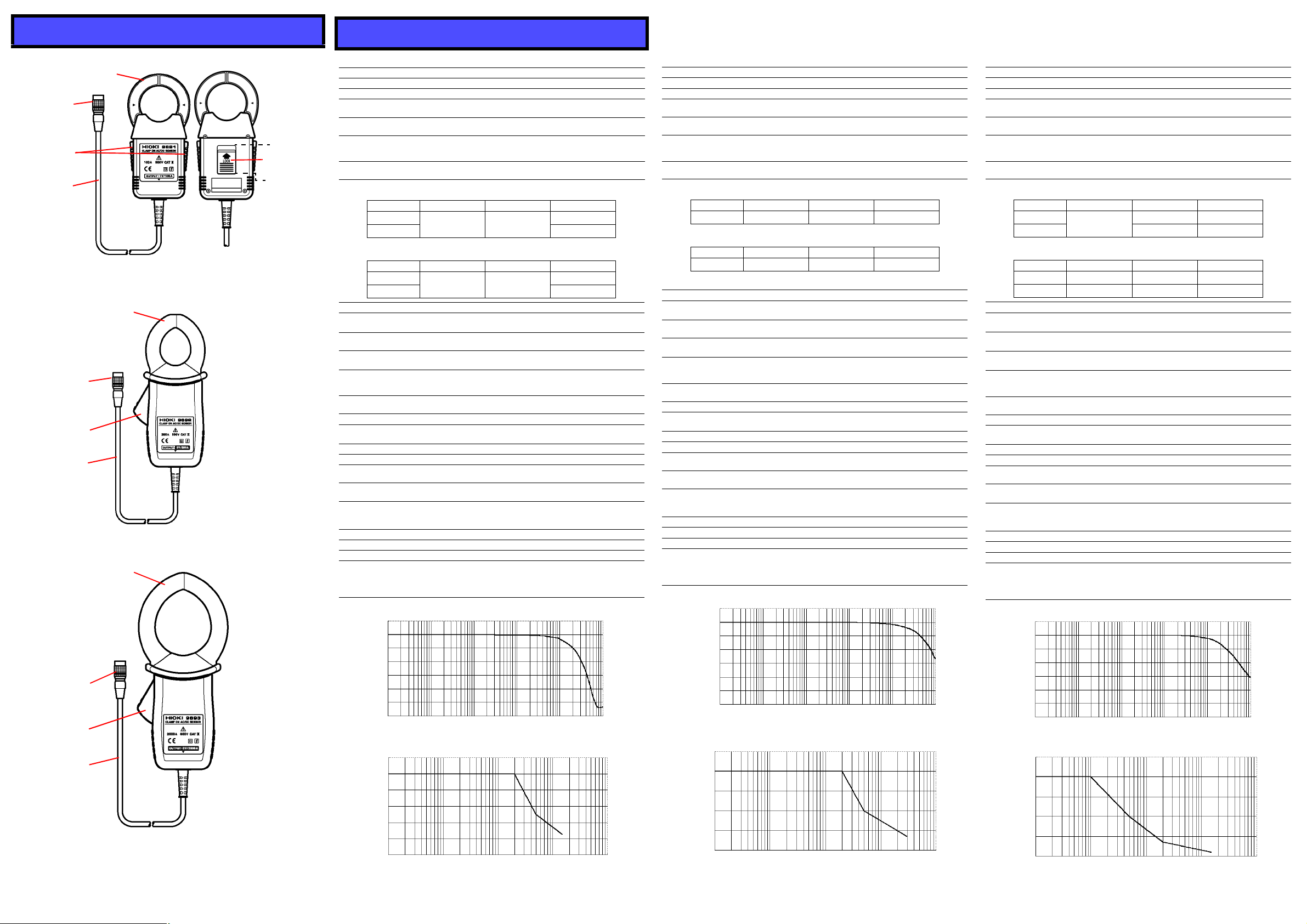
Parts Names
Output
connector
Lever
Cable
Clamp sensor
9691 CLAMP ON AC/DC SENSOR
Front side
Back side
Sensor lock
lever
LOCK
position
UNLOCK
position
Output
connector
Lever
Cable
Clamp sensor
9692 CLAMP ON AC/DC SENSOR
Output
connector
Lever
Cable
Clamp sensor
9693 CLAMP ON AC/DC SENSOR
9693 Frequency characteristics
Frequency (Hz)
f
Specifications
9691 CLAMP ON AC/DC SENSOR
Rated current AC/DC 100 A
Output voltage AC/DC 1 V/100 A
Output resistance 100 Ω or less
Maximum permissi-
ble input
Maximum peak cur-
rent value
Accuracy guarantee
for temperature and
humidity
Guaranteed accuracy period
(1) Continuous input
Range DC to 66Hz 66 to 500Hz
0 to 80A
80 to 100A
(2) Peak input
Range DC to 66Hz 66 to 500Hz
0 to 110A
110 to 150A
Frequency band DC to 10 kHz (-3dB)
Effect of conductor
position
Effect of external
electromagnetic field
Temperature
characteristics
Operating
temperature and
humidity range
Storage
temperature range
Location for use Indoor, altitude up to 2000 m (6566 feet)
Maximum permitted
circuit voltage
Dielectric strength 5.55 kV AC for 1 minute (sensor - case, sensor - circuit)
Power supply ± 5 V ±0.25 V (supply from the outside)
Maximum rated
power
Measurable
conductor diameter
Dimensions Approx. 53W x 129H x 18D mm
Mass Approx. 230 g (8.1 oz.) (including batteries)
Cable length Approx. 2 m (6.5 feet)
Accessory Instruction manual 1
Applicable
standards
5
0
-5
-10
-15
GAIN (dB)
-20
-25
-30
120
100
80
60
Input current (A)
40
20
0
10
100 Arms continuous (Derating according to frequency)
150 A
23°C±5°C(73°F±9°F), 80%RH or less, no condensation
1 year
(Opening and closing of the sensor: 10,000 times)
±1.0%rdg.±0.5mV ±1.0%rdg.±0.5mV
±1.0%rdg.±2mV ±1.0%rdg.±2mV
±2.0%rdg.±0.5mV
±2.5%rdg.±0.5mV
±2.0%rdg.±2mV
±2.5%rdg.±2mV
Within ±1.0% (at 80 A (55 Hz))
0.5 A equivalent or less (in an external electromagnetic
field of 400 A/m)
0 to 40°C range: 0.1 x accuracy specifications/°C
32 to 104°F range: 0.18 x accuracy specifications/°F
0 to 40°C, 32 to 104°F, 80% RH or less; no condensation
-10 to 50°C, 14 to 122°F, 80% RH or less; no condensation
600 V
50 mVA
φ35 mm (1.38") or less
Approx. 2.09"W x 5.08"H x 0.71"D
(excluding protruding parts)
SafetyEN61010
Measurement categories III (Anticipated Transient Overvoltage: 6000 V), Pollution Degree 2
EMC EN61326
9691 Frequency characteristics
100101
Frequency (Hz)
9691 Derating according to frequency
Frequency (Hz)
1k
1k100
10k
10k
100k
100k
9692 CLAMP ON AC/DC SENSOR 9693 CLAMP ON AC/DC SENSOR
Rated current AC/DC 200 A
Output voltage AC/DC 2 V/200 A
Output resistance 100 Ω or less
Maximum permissi-
ble input
Maximum peak cur-
rent value
Accuracy guarantee
for temperature and
humidity
Guaranteed accuracy period
(1) Continuous input
Range DC to 66Hz 66 to 1kHz
0 to 200A
(2) Peak input
Range DC to 66Hz 66 to 1kHz
0 to 300A
200 Arms continuous (Derating according to frequency)
300 A
23°C±5°C(73°F±9°F), 80%RH or less, no condensation
1 year
(Opening and closing of the sensor: 10,000 times)
±1.0%rdg.±0.5mV ±1.0%rdg.±0.5mV ±2.0%rdg.±0.5mV
±1.0%rdg.±2mV ±1.0%rdg.±2mV ±2.0%rdg.±2mV
Frequency band DC to 20 kHz (-3dB)
Effect of conductor
position
Effect of external
electromagnetic field
Temperature
characteristics
Operating
temperature and
humidity range
Storage
temperature range
Within ±0.5%
0.7 A equivalent or less (in an external electromagnetic
field of 400 A/m)
0 to 40°C range: 0.1 x accuracy specifications/°C
32 to 104°F range: 0.18 x accuracy specifications/°F
0 to 40°C, 32 to 104°F, 80% RH or less; no condensation
-10 to 50°C, 14 to 122°F, 80% RH or less; no condensa-
tion
Location for use Indoor, altitude up to 2000 m (6566 feet)
Maximum permitted
600 V
circuit voltage
Dielectric strength 5.55 kV AC for 1 minute (sensor - case, sensor - circuit)
Power supply ± 5 V ±0.25 V (supply from the outside)
Maximum rated
power
Measurable
conductor diameter
50 mVA
φ33 mm (1.30") or less
Dimensions Approx. 62W x 167H x 35D mm
Approx. 2.44"W x 6.57"H x 1.38"D
(excluding protruding parts)
Mass Approx. 410 g (14.5 oz.) (including batteries)
Cable length Approx. 2 m (6.5 feet)
Accessory Instruction manual 1
Applicable
standards
GAIN (dB)
Input current (A)
250
200
150
100
5
0
-5
-10
-15
-20
-25
-30
50
0
10
SafetyEN61010
Measurement categories III (Anticipated Transient Over-
voltage: 6000 V), Pollution Degree 2
EMC EN61326
9692 Frequency characteristics
100101
Frequency (Hz)
9692 Derating according to frequency
Frequency (Hz)
1k
1k100
10k
10k
100k
100k
Rated current AC/DC 2000 A
Output voltage AC/DC 2 V/2000 A
Output resistance 100 Ω or less
Maximum permissi-
ble input
Maximum peak cur-
rent value
Accuracy guarantee
for temperature and
humidity
Guaranteed accuracy period
(1) Continuous input
Range DC 45 to 66Hz to 45Hz, 66 to 1kHz
0 to 1800A
1800 to 2000A
(2) Peak input
Range DC 45 to 66Hz to 45Hz, 66 to 1kHz
0 to 2300A
2300 to 2840A
2000 Arms (Derating according to frequency)
2840 A
23°C±5°C(73°F±9°F), 80%RH or less, no condensation
1 year
(Opening and closing of the sensor: 10,000 times)
±1.5%rdg.±0.5mV
±1.5%rdg.±2mV ±1.0%rdg.±2mV ±2.0%rdg.±2mV
±6.0%rdg.±2mV ±6.0%rdg.±2mV
Frequency band DC to 15 kHz (-3dB)
Effect of conductor
Within ±0.7%
position
Effect of external
electromagnetic field
Temperat ure
characteristics
Operating
temperature and
humidity range
Storage
temperature range
2.0 A equivalent or less (in an external electromagnetic
field of 400 A/m)
0 to 40°C range: 0.1 x accuracy specifications/°C
32 to 104°F range: 0.18 x accuracy specifications/°F
0 to 40°C, 32 to 104°F, 80% RH or less; no condensation
-10 to 50°C, 14 to 122°F, 80% RH or less; no condensa-
tion
Location for use Indoor, altitude up to 2000 m (6566 feet)
Maximum permitted
600 V
circuit voltage
Dielectric strength 5.55 kV AC for 1 minute (sensor - case, sensor - circuit)
Power supply ± 5 V ±0.25 V (supply from the outside)
Maximum rated
power
Measurable
conductor diameter
50 mVA
φ55 mm (2.17") or less
Dimensions Approx. 62W x 196H x 35D mm
Approx. 2.44"W x 7.72"H x 1.38"D
(excluding protruding parts)
Mass Approx. 500 g (17.6 oz.) (including batteries)
Cable length Approx. 2 m (6.5 feet)
Accessory Instruction manual 1
Applicable
standards
SafetyEN61010
Measurement categories III (Anticipated Transient Over-
voltage: 6000 V), Pollution Degree 2
EMC EN61326
5
0
-5
-10
-15
GAIN (dB)
-20
-25
-30
9693 Derating according to frequency
2500
2000
1500
1000
Input current (A)
500
0
10
100101
Frequency (Hz)
±1.0%rdg.±0.5mV ±2.0%rdg.±0.5mV
10k
-
-
100k
100k
±2.0%rdg.±0.5mV
1k
1k100
10k
 Loading...