

9657
CLAMP ON LEAK SENSOR
Instruction Manual
September 2013 Revised edition 8
Printed in Japan
9657A981-08 13-09H
Warranty
Warranty malfunctions occurring under conditions of normal use
in conformity with the Instruction Manual and Product
Precautionary Markings will be repaired free of charge. This
warranty is valid for a period of one (1) year from the date of
purchase. Please contact the distributor from which you
purchased the product for further information on warranty
Introduction
Thank you for purchasing the HIOKI 9657 CLAMP ON LEAK
SENSOR. To obtain maximum performance from the device,
please read this manual first, and keep it handy for future
reference.
Overview
The 9657 is a voltage output type clamp on sensor compatible to
1A AC measurements. The instrument can be relied upon to
measure subtle current with great accuracy due to the high
magnetic permeability material used for the jaws and magnetic
shield.
Inspection
When you receive the device, inspect it carefully to ensure that no
damage occurred during shipping. If damage is evident, or if it fails
to operate according to the specifications, contact your dealer or
Hioki representative.
Preliminary Checks
Before using the device the first time, verify that it operates
normally to ensure that the no damage occurred during storage
or shipping. If you find any damage, contact your dealer or Hioki
representative.
Before using the device, make sure that the insulation on the
cables is undamaged and that no bare conductors are
improperly exposed. Using the device in such conditions could
cause an electric shock, so contact your dealer or Hioki
representative for repair.
Safety
DANGER
This device is designed to comply with IEC 61010 Safety
Standards, and has been thoroughly tested for safety prior to
shipment. However, mishandling during use could result in injury
or death, as well as damage to the device. Be certain that you
understand the instructions and precautions in the manual before
use. We disclaim any responsibility for accidents or injuries not
resulting directly from device defects.
Safety symbols
This manual contains information and warnings essential for safe
operation of the device and for maintaining it in safe operating
condition. Before using the device, be sure to carefully read the
following safety notes.
The symbol printed on the device indicates that
the user should refer to a corresponding topic in the
manual (marked with the
the relevant function.
In the manual, the symbol indicates particularly
important information that the user should read
before using the device.
Indicates AC (Alternating Current).
Wear appropriate protective insulation (insulating
rubber gloves and boots, helmet and etc.) when
connecting and disconnecting from live electric circuits.
The following symbols in this manual indicate the relative
importance of cautions and warnings.
DANGER
WARNING
CAUTION
NOTE
We define measurement tolerances in terms of f.s. (full s cale) and
rdg.(reading) values, with the following meanings:
f.s. (maximum display value or scale length)
The maximum displayable value or the full length of the scale.
This is usually the maximum value of the currently selected range.
rdg. (reading or displayed value)
The value currently being measured and indicated on the
measuring instrument.
Indicates that incorrect operation presents an
extreme hazard that could result in serious injury
or death to the user.
Indicates that incorrect operation presents a
significant hazard that could result in serious
injury or death to the user.
Indicates that incorrect operation presents a
possibility of injury to the user or damage to the
device.
Indicates advisory items related to performance
or correct operation of the device.
symbol) before using
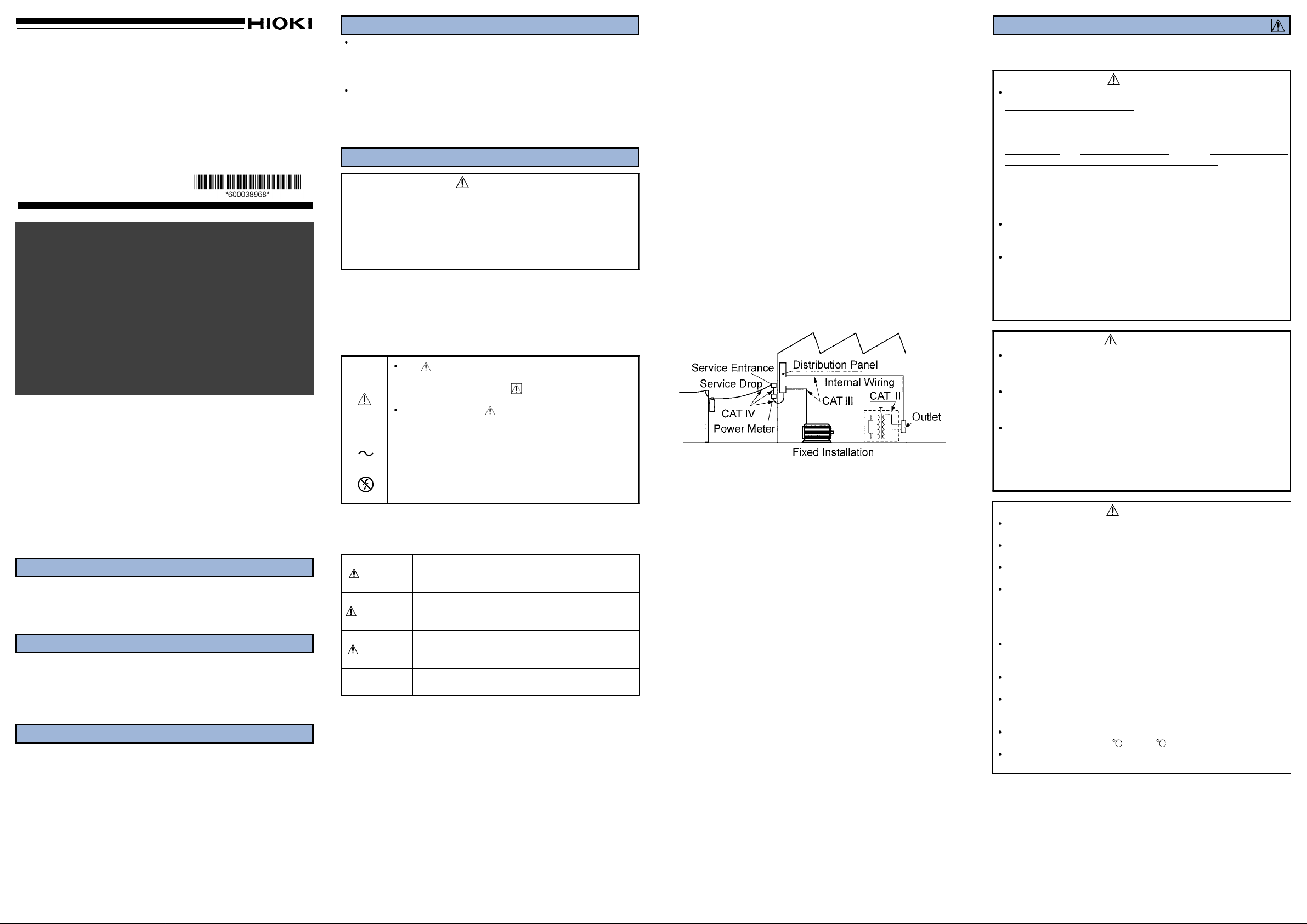
Measurement categories
This product complies with CATIII safety requirements.
To ensure safe operation of measurement products, IEC 61010
establishes safety standards for various electrical environments,
categorized as CAT II to CAT IV, and called measurement
categories. These are defined as follows.
CAT II: Primary electrical circuits in equipment connected to a
wall outlet via a power cord (portable tools, household
appliances, etc.)
CAT II covers directly measuring electrical outlet
receptacles.
CAT III: Primary electrical circuits of heavy equipment (fixed
installations) connected directly to the distribution panel,
and feeders between the distribution panel and outlets.
CAT IV: The circuit from the service drop to the service entrance,
then to the power meter and to the primary overcurrent
protection device.
Using a measurement product in an environment designated with
a higher-numbered category than that for which the product is
rated could result in a severe accident, and must be carefully
avoided.
Use of a measurement instrument that is not CAT-rated in CAT II
to CAT IV measurement applications could result in a severe
accident, and must be carefully avoided.
Notes on Use
Follow these precautions to ensure safe operation and to obtain
the full benefits of the various functions.
DANGER
When conductors being measured carry in excess of the
safe voltage level (SELV-E) and not more than 300 V, to
prevent short circuits and electric shock while the clamp
jaws is open, make sure that conductors to be measured
are insulated with material conforming to (1) Measurement
Category III
Requirements for Working Voltages of 300 V.
Refer to the following standards regarding the meanings of
underlined terms.
IEC 61010-1
IEC 61010-2-031
IEC 61010-2-032
To avoid short circuits and potentially life-threatening
hazards, never attach the device to a circuit that operates
at more than the 300Vrms, or over bare conductors.
The device should only be connected to the secondary
side of a breaker, so the breaker can prevent an accident if
a short circuit occurs. Connections should never be made
to the primary side of a breaker, because unrestricted
current flow could cause a serious accident if a short
circuit occurs.
Do not allow the device to get wet, and do not take
measurements with wet hands. This may cause an electric
shock.
To avoid electric shock when measuring live lines, wear
appropriate protective gear, such as insulated rubber
gloves, boots and a safety helmet.
To avoid electric shock when measuring the ground
conductor on a transformer E (PE) connection site, be
careful not to approach high voltage devices or
conductors. Also, if close to high voltage charging
devices or if measurement is otherwise difficult, first
change the route of the grounding wire.
Note that the device may be damaged if current exceeding the
selected measurement range is applied for a long time.
Avoid stepping on or pinching the cable, which could damage
the cable insulation.
Keep the cables well away from heat sources, as bare
conductors could be exposed if the insulation melts.
Do not store or use the device where it could be exposed to
direct sunlight, high temperature or humidity, or condensation.
Under such conditions, the device may be damaged and
insulation may deteriorate so that it no longer meets
specifications.
To avoid damage to the device, protect it from physical shock
when transporting and handling. Be especially careful to avoid
physical shock from dropping.
Keep the clamp jaws and core slits free from foreign objects,
which could interfere with clamping action.
This device is not designed to be entirely water- or dust-proof.
Do not use it in an especially dusty environment, nor where it
might be splashed with liquid. This may cause damage.
This device is designed for use indoors. It can be operated at
temperatures between 0 and 50 without degrading safety.
Adjustments and repairs should be made only by technically
qualified personnel.
NOTE
Correct measurement may be impossible in the presence of
strong magnetic fields, such as near transformers and highcurrent conductors, or in the presence of strong electromagnetic
fields such as near radio transmitters.
, (2) Pollution Degree 2, and (3) Basic Insulation
WARNING
CAUTION
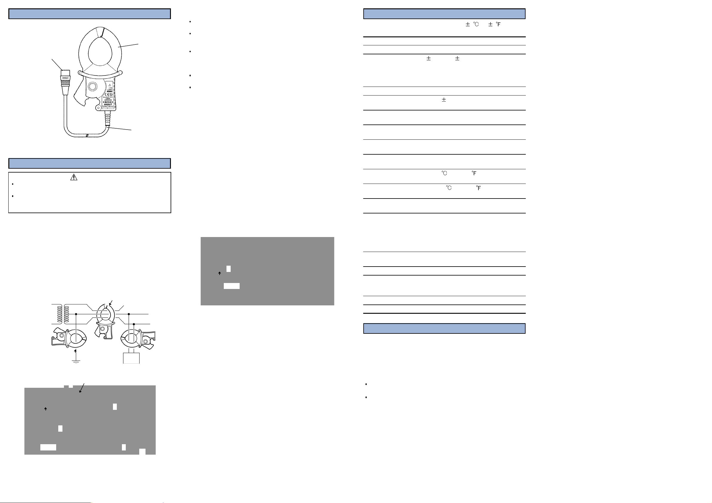
Part Names
R
O
A
Maximum
Effect
p
Effect
m
R
c
D
Maximum
to
O
a
S
a
L
S
D
c
c
E
Mass
A
Jaws
Output connector
Cable
Measurement Procedure
CAUTION
To avoid damaging the output cable, grasp the connector, not
the cable, when unplugging the cable.
To prevent damage to the instrument and sensor, never
connect or disconnect a sensor while the power is on, or while
the sensor is clamped around a conductor.
1. Connect the output connector to the clamp terminal of the
device.
2. Open the jaws, then clamp the conductor.
3. Make sure that the tips of jaws are fully closed.
Connections method
Clamp the sensor on the conductor, so that the conductor passes
through the center of the clamp jaws. For measurement of
grounded leads, clamp the sensor on one lead only (see a). For
overall measurements, clamp the sensor on the entire circuit path
(see B).
single-phase 3-lead circuits
Transformer
Ig: leak Current
three-phase 3-lead
circuits
Ig
a
a
Ig
E (PE)
clamp all three leads of the circuit
b
clamp all three leads
b
b
b
of the circuit
Load
device
Load
device
NOTE
For measurement of single-phase 2-lead circuits, clamp both
leads of the circuit.
For measurement of three-phase 4-lead circuits, clamp all four
leads of the circuit. If this is not possible, the measurement
can also be carried out on the ground lead of the equipment.
If a strong current (on the order of 100 A) is flowing in an
adjacent circuit, accurate measurement may not be possible.
Perform the measurement at a sufficient distance from other
current-carrying conductors.
The frequency of special waveforms such as at the secondary
side of an inverter may not be indicated correctly.
Do not input a current which exceeds the rated current.
Checking for insulation faults
Normally, for a E (PE) grounding installation of a transformer, the
measurement will first be made to check for overall circuit leak
current in the ground lead (a). Current changes can be used to
diagnose the leak current condition.
When leak current has been detected, the measurement should
proceed from the power source towards the load, using overall
measurement.
1. If an insulation fault in the wiring has occurred at position A in
the illustration, leak current will be detected at position b using
overall m easurement, but not at position b'.
2. If an insulation fault in the load equipment has occurred at
position B in the illustration, leak current will be detected at
position c using overall measurement, but not at position c'.
3. For detection of intermittent leak current conditions (such as
only when a certain piece of equipment is operating), the use of
a level recorder will be helpful.
single-phase 3-lead
circuits
a
Ig
E (PE)
b
b′
c
A
Load
device
B
c′
Load
device
Specifications
Accuracy is guaranteed for one year at 23
80% RH. (Opening and Closing of the Sensor: Maximum 10000 times)
ated current 1.0 AAC
utput voltage 25 mVAC/A
mplitude accuracy 1.0% rdg. 12μV (45 to 66 Hz, at the
clamp jaws center)
(Regarding the accuracy: refer to the
specification of the each instrument that
you use with this device)
input current 60 A continuous at 45 to 66 Hz
of conductor
osition
of external
agnetic fields
emaining electric
urrent character
within 0.1% (in any direction from
sensor center)
400 AAC/m corresponds to 5 mA,
Max. 7.5 mA
Max. 5 mA (in 100 A go and return
electric wire)
ielectric strength 3536 Vrms for 15 seconds
(between clamp window and case)
rated voltage
Max. 300 Vrms
earth
perating temperature
nd humidity range
torage temperature
nd humidity range
0to50 (32to122 ), Max. 80%RH (no
condensation)
-10to60 (14to140 ), Max. 80%RH (no
condensation)
ocation for use Altitude up to 2000 m (6562 feet),
Indoors
tandards applying
EMC
Safety
EN 61326
EN 61010
Measurement Category III, Pollution
Degree 2 (anticipated transient
overvoltage 4000 V)
iameter of measurable
Within φ 40 mm (1.57")
onductor
able length Approx. 3 m (118.11")
xternal dimensions Approx. 74W x 145H x 42D mm
(2.91"W x 5.71"H x 1.65"D)
(excluding protrusions)
Approx. 340 g (12.0 oz.)
ccessories Instruction manual
5 (73 9 )andMax.
Maintenance and Service
Cleaning the device
To clean the device, wipe it gently with a soft cloth moistened with
water or mild detergent. Never use solvents such as benzene,
alcohol, acetone, ether, ketones, thinners or gasoline, as they can
deform and discolor the case.
Service
If the device seems to be malfunctioning, contact your dealer or
Hioki representative.
When sending the device for repair, pack the device carefully so
that it will not be damaged during shipment, and include a
detailed written description of the problem. Hioki cannot be
responsible for damage that occurs during shipment.
E (PE)
a
E
3
PE
 Loading...