

Page 1
00_Cover_WSC70_A36_P1.qxd 1.6.2006 10:23 Seite 4
WSC 70-A36
WSC 55-A24
Bedienungsanleitung de
Operating instructions en
Mode d’emploi fr
Manual de instrucciones es
Istruzioni d’uso it
Gebruiksaanwijzing nl
Brugsanvisning da
Bruksanvisning sv
Käyttöohje fi
Manual de instruções pt
Οδηγιες χρησεως
Lietoßanas pamåcîba lv
Instrukcija lt
Kasutusjuhend et
el
236297
Page 2
00_Cover_WSC70_A36_P1.qxd 1.6.2006 10:23 Seite 5
1
7 "[
*≠
+±
"≠
"{
+}
"|
4
"}
2
3
12+“8+{
5
6
+[+|"]
+] +Ç
"±"“"#"Ç +±
9
+≠
+#
Page 3
7
6
4
3
5
1
7
1
2
3/4
1
0-45°(50)
2/4
1
2/5
2/5
3/4
3/4
1
00_Cover_WSC70_A36_P1.qxd 1.6.2006 10:23 Seite 7
2
1
2
3
4
4
≤
5mm
5mm
≤
3
5/6
5
6
7
Page 4
00_Cover_WSC70_A36_P1.qxd 1.6.2006 10:23 Seite 8
8
1400-2
WGS
200 mm
1400/3000 mm
WGS 1400-2
60° 45° 30° 22.5° 0° 22.5°30° 45°
Page 5
360°
00_Cover_WSC70_A36_P1.qxd 1.6.2006 10:23 Seite 1
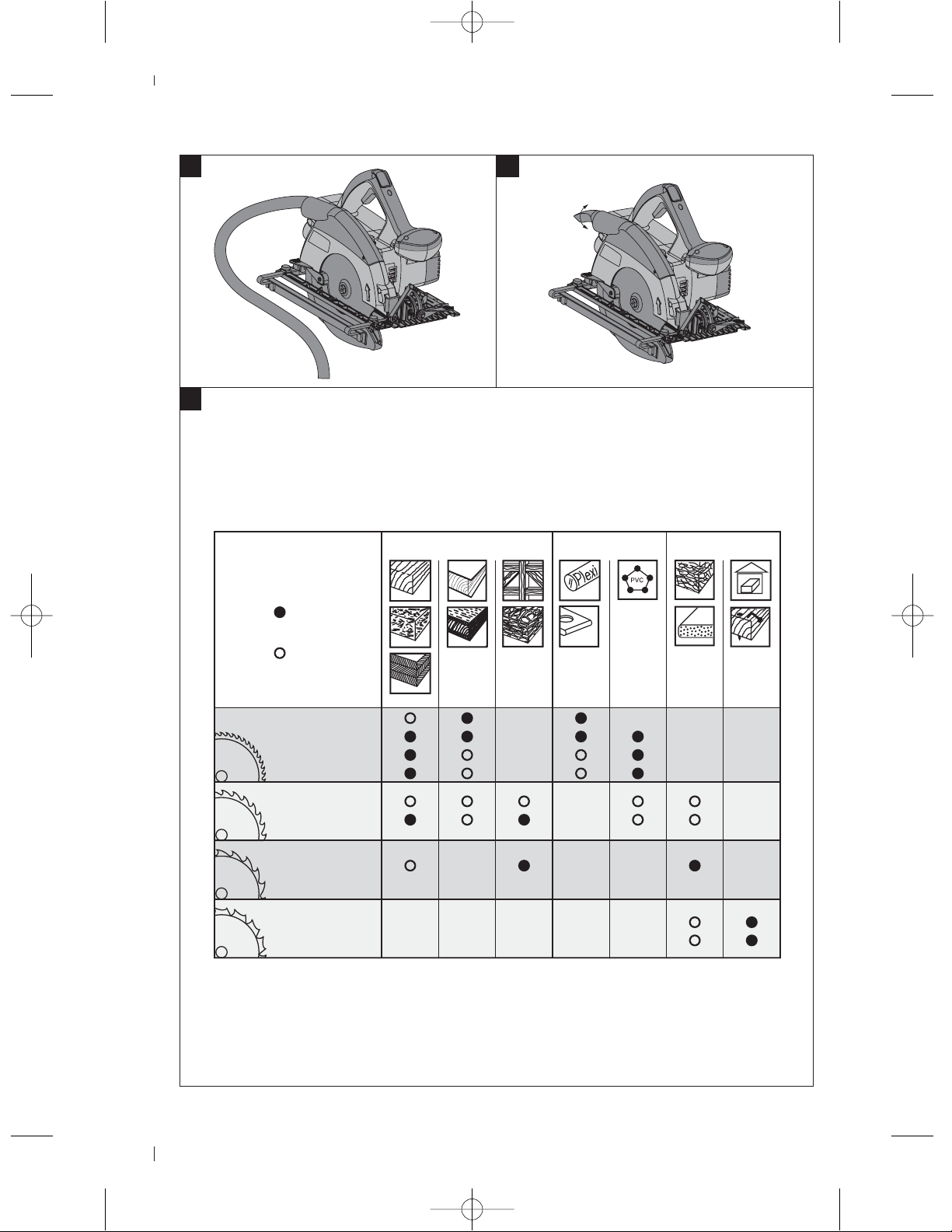
9
11
...optimal geeignet
ideal
tout indiquée
...geeignet
good
indiquée
10
Holz / Wood / Bois Kunststoff / Synthetics /
Plastiques
Corian
Variocor
Andere / Others /
Autre chose
z54
QualiCut
z48
z42
z42-A
MultiCut
z24-A
z42-A
QuickCut
SpecialCut
z18
z18
z14
AKKU / BATTERY / ACCU / BATERIAS / BATTERI / AKU / AKUMULATORY / AKKмMмгьнйк
Page 6
WSC 70ತA36 / WSC 55ತA24 cordless circular
saw
Release buttons with additional function
It is essential that the operating instructions
are read before the power tool is operated
for the first time.
Always keep these operating instructions
together with the power tool.
Ensure that the operating instructions are
with the power tool when it is given to other
persons.
Contents Page
1. General information 17
2. Description 18
3. Accessories 20
4. Technical data 20
5. Safety rules 21
6. Before use 25
7. Operation 26
8. Care and maintenance 29
9. Troubleshooting 30
10. Disposal 30
11. Manufacturer’s warranty - tools 31
12. EC declaration of conformity 32
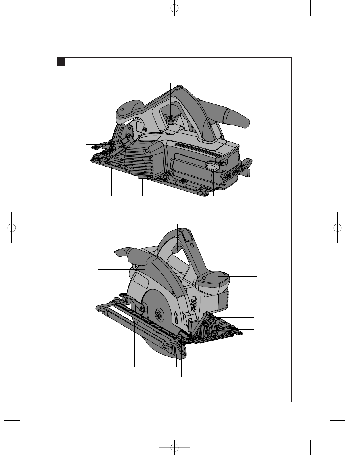
Operating controls and parts 1
Battery
@
;
(charge status display activation)
Charge status and fault display (Li-ion battery)
=
Control switch
%
Switch-on interlock
&
Auxiliary grip
(
Drive spindle lockbutton
)
Hexagon socket wrench
+
Cutting angle scale
§
Clamping lever for cutting angle adjustment
/
Clamping screws for the parallel guide
:
Clamping lever for cutting depth adjustment
·
45°cutting line indicator
$
0°cutting line indicator
£
Parallel guide (rip fence)
|
Pivoting guard
¡
Riving knife
Q
Base plate
W
Guard
E
Rotatable chip ejector
R
Drive spindle
T
Mounting flange
Z
Clamping flange
U
Clamping screw
I
Cutting depth scale
O
Riving knife fastening screws
P
Pivoting guard operating lever
Ü
Chip deflector guard
[
Chip deflector guard release
]
Angle extender for 50° cuts
Æ
en
1. General information
1.1 Safety notices and their meaning
DANGER
Draws attention to imminent danger that could lead
to serious bodily injury or fatality.
WARNING
Draws attention to a potentially dangerous situation
that could lead to serious personal injury or fatality.
CAUTION
Draws attention to a potentially dangerous situation
that could lead to slight personal injury or damage to
the equipment or other property.
NOTE
Used to draw attention to an instruction or other
useful information.
17
Page 7
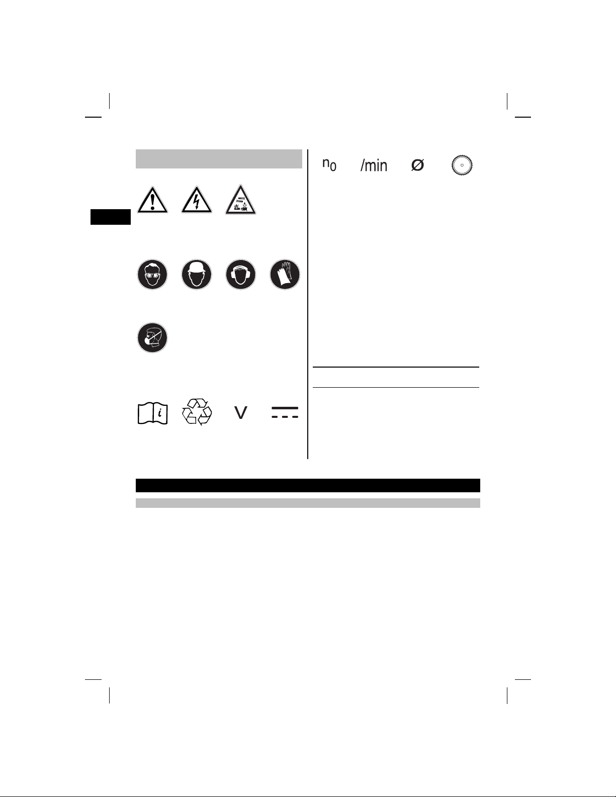
1.2 Explanation of the pictograms and other
information
Warning signs
en
General
warning
Warning:
electricity
Warning:
caustic
substances
Obligation signs
Wear eye
protection
Wear a hard
hat
Wear ear
protection
Wear
protective
gloves
Rated speed
under no load
Revolutions
per minute
Diameter Saw blade
1 These numbers refer to the corresponding illustrations. The illustrations can be found on the fold-out
cover pages. Keep these pages open while studying
the operating instructions.
In these operating instructions, the designation “the
power tool” always refers to the WSC 70ತA36 or
WSC 55ತA24 cordless circular saw.
Location of identification data on the power tool
The type designation can be found on the type identification plate and the serial number on the side of
the motor housing. Make a note of this data in your
operating instructions and always refer to it when
making an enquiry to your Hilti representative or
service department.
Wear
breathing
protection
Symbols
Read the
operating
instructions
before use
Return waste
material for
recycling.
Volts Direct current
Type:
Serial no.:
2. Description
2.1 Use of the product as directed
The power tool is a hand-held, cordless circular saw.
The power tool is designed for sawing wood or wood-like materials, plastics, drywall panel (plasterboard),
gypsum fiberboard and composite materials with a thickness of up to 55 or 70 mm (depending on model) and
for bevel cuts at angles between 0 ° and 50 °.
Working on materials hazardous to the health (e.g. asbestos) is not permissible.
The power tool is designed for professional use and may be operated, serviced and maintained only by trained,
authorized personnel. This personnel must be informed of any special hazards that may be encountered. The
power tool and its ancillary equipment may present h azards when used incorrectly by untrained personnel or
when used not as directed.
The working environment may be as follows: construction site, workshop, renovation, conversion or new
construction.
Modification of the power tool is not permissible.
18
Page 8

The use of saw blades that do not comply with the given specification (e.g. diameter, thickness) or the use of
ತ
cutting and grinding discs or blades made from high-alloy steel (HSS steel) is not permissible.
Sawing metals is not permissible.
Do not use the power tool to cut tree branches or logs.
Do not use the battery as a power source for other unspecified appliances.
To avoid the risk of injury, use only genuine Hilti accessories and insert tools.
Observe the information printed in the operating instructions concerning operation, care and maintenance.
2.2 Switches
Control switch with switch-on interlock
2.3 Grips
Grip and auxiliary grip
2.4 Protective device
Blade guard and pivoting guard
2.5 Lubrication
Grease lubrication
2.6 Deep discharge protection
To extend the life of the battery and the motor, the electronic control system is designed to audibly reduce
blade drive speed when excessive pressure is applied, up to the point at which the blade stalls completely
when pressure is maintained causing activation of the power cut-out.
CAUTION
So long as the control switch remains depressed, the power tool runs up to speed again when the pressure
applied to it is released, just like a mains-powered tool.
en
2.7 Li
ion battery charge status
When a Li-ion battery is used, the charge status can be indicated by gently pressing one of the battery release
buttons (press until resistance is felt - do not release the battery). The display on the rear of the battery
provides the following information:
LEDs light constantly LEDs blink Charge status C
LED 1,2,3,4
LED 1,2,3
LED 1,2
LED 1
-
2.8 Items supplied as standard
1 Power tool
1Sawblade
1 Hexagon socket wrench
1 Operating instructions
1 Hilti toolbox (optional)
1 Cardboard box (optional)
-
-
-
-
LED 1
C ฺ 75 %
50 % ู C<75%
25 % ู C<50%
10 % ู C<25%
C<10%
19
Page 9

2.9 Additional items required for operating the tool
ತ
For the WSC 70ತA36: aB36/2.4NiCdbatteryandaC7/36ತACS charger or a B36/3.3 Li-ion battery and a
C4/36LiತACS charger.
For the WSC 55ತA24: a B24/2.0 NiCd battery and a C7/24 or C7/36ತACS charger.
NOTE
Depending on the version, these items may be supplied with the power tool.
en
3. Accessories
Accessories for the WSC 70ತA36
Charger C7/36-ACS
Charger C4/36-ACS
Battery
Battery B36/3.3 Li-ion
Parallel guide (rip fence) WPG 70/55
Guide rail WGS 1400ತ2B
Accessories for the WSC 55
Charger C7/24
Charger C7/36-ACS
Battery
Parallel guide (rip fence) WPG 70/55
Guide rail WGS 1400ತ2B
A24
B36/2.4 NiCd
B24/2.0 NiCd
4. Technical data
Power tool WSC 70ತA36 WSC 55ತA24
Rated voltage (DC voltage)
Weight in accordance with EPTA
procedure 01/2003
Dimensions (L x W x H) 307 mm x 393 mm x 233 mm 296 mm x 381 mm x 233 mm
Base plate 193 mm x 320 mm 193 mm x 320 mm
Maximum saw blade diameter 190 mm 160 mm
Minimum saw blade diameter 176 mm 149 mm
Saw blade disc thickness
Kerf width
Saw blade arbor size
Cutting depth Cutting angle 90°: 70 mm
Riving knife thickness
Speed under no load
20
36 V 24 V
0kg 0kg
0.5to1.5mm 0.5to1.5mm
1.6to2mm 1.5to2mm
30 mm 20 mm
Cutting angle 90°: 55 mm
Cutting angle 50°: 45 mm
Cutting angle 45°: 51 mm
1.5 mm 1.4 mm
3,900 r.p.m. 3,300 r.p.m.
Cutting angle 50°: 36 mm
Cutting angle 45°: 40 mm
Page 10

Noise and vibration information for the WSC 70ತA36 (measured in accordance with EN 60745-2-
ತ
5 prAA: 2006):
Typical A-weighted sound power level 108 dB (A)
Typical A-weighted emission sound pressure level. 97 dB (A)
Uncertainty for the given sound level
Triaxial vibration values (vibration vector sum)
Sawing in wood, A
Uncertainty (K) 1.5 m/st
Noise and vibration information for the WSC 55
5 prAA: 2006):
Typical A-weighted sound power level 106 dB (A)
Typical A-weighted emission sound pressure level. 95 dB (A)
Uncertainty for the given sound level
Triaxial vibration values (vibration vector sum)
Sawing in wood, A
Uncertainty (K) 1.5 m/st
Battery B 36/2.4 NiCd B 36/3.3 Li-ion B 24/2.0 NiCd
Rated voltage 36 V 36 V 24 V
Capacity
Energy capacity 86.4 Wh 118.8 Wh 48 Wh
Temperature monitoring
Weight 2.08 kg 1.65 kg 1.37 kg
Type of cell
No. of cells
h
h
2.4Ah 3.3Ah 2Ah
NTC NTC NTC
Nickel-cadmium Lithium-ion Nickel-cadmium
30 30 20
3dB(A)
<2.5m/st
A24 (measured in accordance with EN 60745-2-
3dB(A)
<2.5m/st
en
5. Safety rules
NOTE
The safety rules in section 5.1 contain all general
safety rules for power tools which, in accordance
with the applicable standards, require to be listed in
the operating instructions. Accordingly, some of the
rules listed may not be relevant to this tool.
5.1 General safety rules
WARNING! Read all instructions! Failure to follow all
instructions listed below may result in electric shock,
fire and/or serious injury. The term “power tool” in
all of the warnings listed below refers to your mainsoperated (corded) power tool or battery-operated
(cordless) power tool. SAVE THESE INSTRUCTIONS.
5.1.1 Work area safety
a) Keep work area clean and well lit. Cluttered or
dark areas invite accidents.
b) Do not operate power tools in explosive atmo-
spheres, such as in the presence of flammable
liquids, gases or dust. Power tools create sparks
which may ignite the dust or fumes.
c) Keep children and bystanders away while oper-
ating a power tool. Distractions can cause you to
lose control.
5.1.2 Electrical safety
a) Power tool plugs must match the outlet. Never
modify the plug in any way. Do not use any
21
Page 11

adapter plugs with earthed (grounded) power
tools. Unmodified plugs and matching outlets will
reduce risk of electric shock.
b) Avoid body contact with earthed or grounded
surfaces such as pipes, radiators, ranges and
refrigerators. There is an increased risk of electric
shock if your body is earthed or grounded.
en
c) Do not expose power tools to rain or wet con-
ditions. Water entering a power tool will increase
theriskofelectricshock.
d) Do not abuse the cord. Never use the cord for
carrying, pulling or unplugging the power tool.
Keep cord away from heat, oil, sharp edges
or moving parts. Damaged or entangled cords
increase the risk of electric shock.
e) When operating a power tool outdoors, use an
extension cord suitable for outdoor use. Use of a
cord suitable for outdoor use reduces the risk of
electric shock.
5.1.3 Personal safety
a) Stay alert, watch what you are doing and use
common sense when operating a power tool. Do
not use a power tool while you are tired or under
the influence of drugs, alcohol or medication. A
moment of inattention while operating power tools
may result in serious personal injury.
b) Use safety equipment. Always wear eye pro-
tection. Safety equipment such as dust mask,
non-skid safety shoes, hard hat, or hearing protection used for appropriate conditions will reduce
personal injuries.
c) Avoid accidental starting. Ensure the switch is
in the off-position before plugging in. Carrying
power tools with your finger on the switch or
plugging in power tools that have the switch on
invites accidents.
d) Remove any adjusting key or wrench before
turning the power tool on. A wrench or a key left
attached to a rotating part of the power tool may
result in personal injury.
e) Do not overreach. Keep proper footing and bal-
ance at all times. This enables better control of
the power tool in unexpected situations.
f) Dress properly. Do not wear loose clothing or
jewellery. Keep your hair, clothing and gloves
away from moving parts. Loose clothes, jewellery
or long hair can be caught in moving parts.
g) If devices are provided for the connection of dust
extraction and collection facilities, ensure these
are connected and properly used. Use of these
devices can reduce dust-related hazards.
5.1.4 Power tool use and care
a) Do not force the power tool. Use the correct
power tool for your application.Thecorrectpower
tool will do the job better and safer at the rate for
which it was designed.
b) Do not use the power tool if the switch does not
turn it on and off. Any power tool that cannot be
controlled with the switch is dangerous and must
be repaired.
c) Disconnect the plug from the power source
and/or the battery pack from the power tool
before making any adjustments, changing accessories, or storing power tools. Such prevent-
ive safety measures reduce the risk of starting the
power tool accidentally.
d) Store idle power tools out of the reach of children
and do not allow persons unfamil iar with the
power tool or these instructions to operate the
power tool. Power tools are dangerous in the
hands of untrained users.
Maintain power tools. Check for misalignment or
e)
binding of moving parts, breakage of parts and
any other condition that may affect the power
tools operation. If damaged, have the power tool
repaired before use. Many accidents are caused
by poorly maintained power tools.
f) Keep cutting tools sharp and clean. Properly
maintained cutting tools with sharp cutting edges
are less likely to bind and are easier to control.
g) Use the power tool, accessories and tool bits
etc., in accordance with these instructions and
in the manner intended for the particular type
of power tool, taking into account the working
conditions and the work to be performed. Use of
the power tool for operations different from those
intended could result in a hazardous situation.
5.1.5 Battery tool use and care
a) Ensure the switch is in the off position before
inserting battery pack. Inserting the battery pack
into power tools that have the switch on invites
accidents.
b) Recharge only with the charger specified by the
manufacturer. A charger that is suitable for one
type of battery pack may create a risk of fire when
used with another battery pack.
22
Page 12

c) Use power tools only with specifically designated
battery packs. Use of any other battery packs may
create a risk of injury and f ire.
d) When battery pack is not in use, keep it away
from other metal objects like paper clips, coins,
keys, nails, screws, or other small metal objects
that can make a connection from one terminal to
another. Shorting the battery terminals together
may cause burns or a fire.
e) Under abusive conditions, liquid may be ejec-
ted from the battery, avoid contact. If contact
accidentally occurs, flush with water. If liquid
contacts eyes, additionally seek medical help.
Liquids ejected from the battery may cause irritation or burns.
5.1.6 Service
a) Have your power tool serviced by a qualified
repair person using only identical replacement
parts. This will ensure that the safety of the power
tool is maintained.
5.2 Additional safety instructions
5.2.1 Safety instructions for all saws
a) DANGER: Keep hands away from cutting area
and the blade. Keep your second hand on auxiliary handle or motor housing. If both hands are
holding the saw, they cannot be cut by the blade.
b) Do not reach underneath the workpiece. The
guard cannot protect you from the blade below the
workpiece.
c) Adjust the cutting depth to the thickness of the
workpiece. Less than a full tooth of the blade teeth
should be visible below the workpiece.
d) Never hold piece being cut in your hands or
across your leg. Secure the workpiece to a stable
platform. It is important to support the work prop-
erly to minimize body exposure, blade binding, or
loss of control.
e) Hold power tool by insulated gripping surfaces
when performing an operation where the cutting
tool may contact hidden wiring or its own cord.
Contact with a “live” wire will also make exposed
metal parts of the power tool “live” and shock the
operator.
f) When ripping always use a rip fence or straight
edge guide. This improves the accuracy of cut
and reduces the chance of blade binding.
g) Always use blades with correct size and shape
(diamond versus round) of arbor holes. Blades
that do not match the mounting hardware of the
saw will run eccentrically, causing loss of control.
h) Never use damaged or incorrect blade washers
or bolt. The blade washers and bolt were specially
designed for your saw, for optimum performance
and safety of operation.
5.2.2 Further safety instructions for all saws
Causes and operator prevention of kickback:
- Kickback is a sudden reaction to a pinched, bound
or misaligned saw blade, causing an uncontrolled
saw to lift up and out of the workpiece toward the
operator;
- When the blade is pinched or bound tightly by the
kerf closing down, the blade stalls and the motor
reaction drives the unit rapidly back toward the
operator;
- If the blade becomes twisted or misaligned in the
cut,theteethatthebackedgeofthebladecandig
into the top surface of the wood causing the blade
to climb out of the kerf and jump back toward the
operator.
Kickback is the result of saw misuse and/or incorrect
operating procedures and can be avoided by taking
proper precautions as given below.
a) Maintain a firm grip with both hands on the saw
and position your arms to resist kickback forces.
Position your body to either side of the blade,
but not in line with the blade. Kickback could
cause the saw to jump backwards, but kickback
forces can be controlled by the operator, if proper
precautions are taken.
b) When blade is binding, or when interrupting a
cut for any reason, release the trigger and hold
the saw motionless in the material until the
blade comes to a complete stop. Never attempt
to remove the saw from the work or pull the saw
backward while the blade is in motion or kickback may occur. Investigate and take corrective
actions to eliminate the cause of blade binding.
c) When restarting a saw in the workpiece, center
the saw blade in the kerf and check that saw
teeth are not engaged into the material. If saw
blade is binding, it may walk up or kickback from
the workpiece as the saw is restarted.
d) Support large panels to minimize the risk of
blade pinching and kickback. Large panels tend
to sag under their own weight. Supports must be
en
23
Page 13

placed under the panel on both sides, near the line
of cut and near the edge of the panel.
e) Do not use dull or damaged blades. Unsharpened
or improperly set bladesproducenarrowkerf causing excessive friction, blade binding and kickback.
f) Blade depth and bevel adjusting locking levers
must be tight and secure before making cut. If
en
blade adjustment shifts while cutting, it may cause
binding and kickback.
g) Useextracautionwhenmakinga“plungecut”
into existing walls or other blind areas. The
protruding blade may cut objects that can cause
kickback.
5.2.3 Safety instructions for circular saws with
dual-actuation of lower blade g uard or
with trailing guard
a) Check lower guard for proper closing before each
use. Do not operate the saw if lower guard does
not move freely and close instantly. Never clamp
or tie the lower guard into the open position. If
saw is accidentally dropped, lower guard may be
bent. Raise the lower guard with the retracting
handle and make sure it moves freely and does not
touch the blade or any other part, in all angles and
depths of cut.
b) Check the operation of the lower guard spring. If
the guard and the spring are not operating properly, they must be serviced before use. Lower
guard may operate sluggishly due to damaged
parts, gummy deposits, or a build-up of debris.
c) Lower guard should be retracted manually only
for special cuts such as “plunge cuts” and “compound cuts.” Raise lower guard by retracting
handle and as soon as blade enters the material, the lower guard must be released. For
all other sawing, the lower guard should operate
automatically.
d) Always observe that the guard is covering the
bladebeforeplacingsawdownonbenchor
floor. An unprotected, coasting blade will cause
the saw to walk backwards, cutting whatever is in
its path. Be aware of the time it takes for the blade
to stop after switch is released.
5.2.4 Additional safety instructions for all saws
with riving knife
a) Use the appropriate riving knife for the blade
being used. For the riving knife to work, it must
be thicker than the body of the blade but thinner
than the tooth set of the blade.
b) Adjust the riving knife as described in this in-
struction manual. Incorrect spacing, positioning
and alignment can make the riving knife ineffective
in preventing kickback.
c) Always use the riving knife except when plunge
cutting. Riving knife must be replaced after plunge
cutting. Riving knife causes interference during
plunge cutting and can create kickback.
d) For the riving knife to work, it must be engaged
in the workpiece. The riving knife is ineffective in
preventing kickback during short cuts.
e) Do not operate the saw if riving knife is bent.
Even a light interference can slow the closing rate
of a guard.
5.2.5 Personal safety
a) Wear ear protectors. Exposure to noise can cause
hearing loss.
b) Always hold the power tool securely with both
hands on the grips provided. Keep the grips dry,
clean and free from oil and grease.
c) Breathing protection must be worn if the power
tool is used without a dust extraction system for
work that creates dust.
d) Do not operate the power tool without the pro-
tective devices that belong to it.
e) Operate the power tool only as intended and
when it is in faultless condition.
f) Improve the blood circulation in your fingers by
relaxing your hands and exercising your fingers
during breaks between working.
g) Switch the power tool on only after bringing it
into position at the workpiece.
h) Remove the battery before storing or transporting
the power tool.
i) Always guide the power tool away from your
body when working with it.
j) Do not work with the power tool overhead.
k) Do not attempt to brake the speed of the saw
bladebypressingittotheside.
l) Do not touch the clamping flange or the flange
screw while the power tool is running.
m)The kerf must be free of obstructions. Do not saw
into screws and nails etc.
n) Never press the drive spindle lockbutton while
the saw blade is rotating.
o) Never direct the power tool toward persons.
p) Adjust the pressure applied to the saw blade and
the material being cut so that the blade doesn’t
24
Page 14

stall, possibly causing the power tool to kick
back.
5.2.6 Power tool use and care
a) Secure the workpiece. Use clamps or a vice
to secure the workpiece. The workpiece is thus
held more securely than by hand and both hands
remain free to operate the power tool.
b) Check that the insert tools used are compatible
with the chuck system and that they are secured
in the chuck correctly.
5.2.7 Electrical safety
jury through contact with caustic substances may
otherwise result.
d) Do not use batteries other than those approved
for use with the applicable power tool or appliance. Use of other batteries or use of the battery
for purposes for which it is not intended presents
a risk of fire and explosion.
e) Do not charge or continue to use damaged bat-
teries (e.g. batteries with cracks, broken parts,
bent or pushed-in and/or pulled-out contacts).
5.2.9 Work area
a) Ensure that the workplace is well lit.
b) Ensure that the workplace is well ventilated.
Exposure to dust at a poorly ventilated workplace
may result in damage to the health.
en
a) Before beginning work, check the working area
(e.g. using a metal detector) to ensure that no
concealed electric cables or gas and water pipes
are present. External metal parts of the power tool
may become live, for example, when an electric
cable is damaged accidentally. This presents a
serious risk of electric shock.
5.2.8 Battery use and care
a) Observe the special instructions applicable to the
transport, storage and use of Li-ion batteries.
b) Do not expose batteries to high temperatures or
fire. This presents a risk of explosion.
c) Batteries must not be opened or dismantled,
squashed, heated to temperatures over 100°C
or incinerated. A risk of fire, explosion or in-
6. Before use
6.1 Battery use and care
NOTE
Battery performance drops at low temperatures.
Never use the battery until the cells become fully
discharged. Change to the second battery as soon
5.2.10 Personal protective equipment
a) The user and any other persons in the vicinity
must wear suitable eye protection, a hard hat,
ear protection, protective gloves and breathing
protection while the power tool is in use.
5.2.11 Protective device
a) Do not switch the power tool on if the saw blade,
the blade guard, the pivoting guard or the riving
knife are not fitted correctly.
as a drop in performance is noticed. Recharge the
battery immediately so that it is ready for reuse.
Store the battery in a cool, dry place. Never store
the battery where it is exposed to direct sunlight or
sources of heat, e.g. on heaters / radiators or behind a
motor vehicle windscreen. Batteries that have reached
the end of their life must be disposed of safely and
correctly to avoid environmental pollution.
25
Page 15

Insert the battery in the corresponding charger.
6.2 Charging the battery
6.2.3 Recharging Li-ion batteries
Li-ion batteries are ready for use at any time, even
when only partly charged. Charging progress is indicated by the LEDs (see section “Charge status of
Liತion batteries”).
en
CAUTION
UseonlytheHiltichargerslistedunder“Accessories”.
DANGER
Ensure that the outer surfaces of the battery are clean
and dry before inserting it in the corresponding charger. Read the operating instructions for the charger
for further information about the charging procedure.
6.2.1 Charging a new battery for the first time
A new battery must be charged correctly for the
first time before use. This will ensure that the cells
form correctly. Incorrect initial charging may have a
permanent, negativeeffect on battery capacity. Please
refer to the applicable battery charger’s operating
instructions for information about initial charging.
6.2.2 Recharging a NiCd battery
NiCd batteries should be charged fully each time they
are charged.
7. Operation
NOTE
If the blade is stalled for a long time, the tool will
not restart by itself when the pressure applied to it
is released. The switch-on interlock and the control
switch must be pressed again.
CAUTION
Wear protective gloves. The cutting edges of the saw
blade teeth are sharp. The cutting edges may present
ariskofinjury.
6.3 Fitting the battery
CAUTION
Use only Hilti B 36/2.4 NiCd or B36/3.3 Li-ion batteries
for the WSC 70ತA36, and B 24/2.0 NiCd batteries for
the WSC 55ತA24.
CAUTION
Check that the power tool is switched off and the
switch interlock activated before fitting the battery.
Use only the Hilti batteries approved for use with this
power tool.
1. Push the battery into the power tool from the rear
as far as it will go and until it is heard to engage
with a double click.
2. CAUTION A falling battery may present a risk of
injury to yourself or others.
Check that the battery is seated securely in the
power tool.
6.4 Removing the battery
1. Press both battery release buttons.
2. Pull the battery out of the power tool toward the
rear.
CAUTION
Wear protective glasses and a dust mask. The
sawing operation swirls up dust and wood chips into
the air. The dust and wood chips may be harmful to
theeyesandrespiratorysystem.
CAUTION
Wear ear protectors. The power tool and the sawing
operation generate noise. Exposure to noisecancause
loss of hearing.
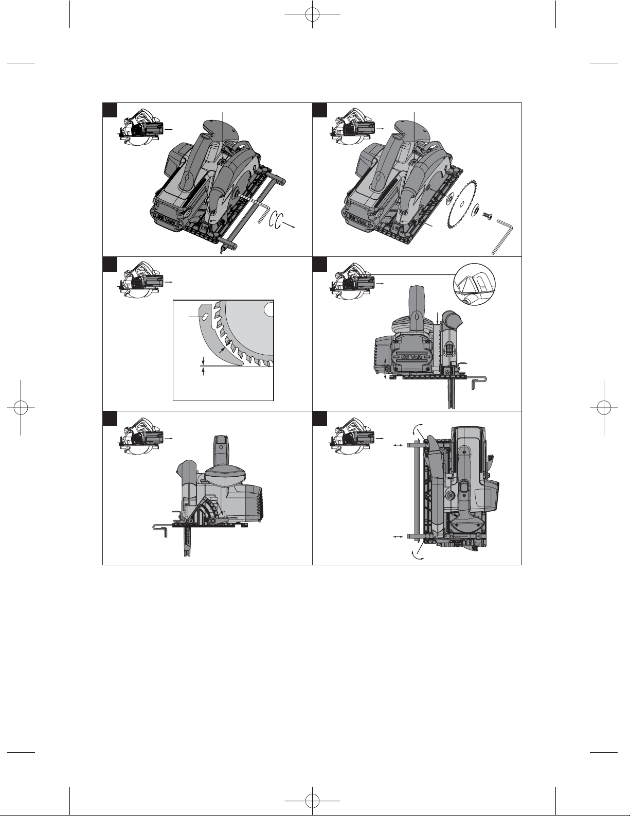
7.1 Changing the saw blade
26
Page 16

CAUTION
Wear protective gloves when changing blades. The
blade, the clamping flange and the clamping screw
get hot.
CAUTION
Check that the blade to be fitted complies with
the technical requirements and that it is well
sharpened. A sharp saw blade is an essential re-
quirement for a perfect cut.
7.1.1 Removing the saw blade 2
1. Pull the battery out of the power tool.
2. Press the drive spindle lockbutton.
3. Turn the saw blade clamping screw with the hex.
socket wrench until the locking pin engages fully.
4. Use the hex. socket wrench to release the clamping screw by turning it counterclockwise.
5. Remove the clamping screw from the outer
clamping flange.
6. Open the pivoting guard by swinging it to the side
and then remove the saw blade.
7.1.2 Fitting the saw blade 3
1. Pull the battery out of the power tool.
2. Clean the mounting flange and the clamping
flange.
3. Fit the mounting flange.
4. Open the pivoting guard.
5. Fit the new saw blade (observe the direction of
rotation arrow on the blade).
6. Fit the outer clamping flange.
7. Secure the clamping flange by tightening the
clamping screw in a clockwise direction. When
doing so, press the spindle lockbutton as before
(see “Removing the blade”).
8. Before using the power tool, check that the saw
blade is securely attached.
7.2 Adjusting the riving knife 4
Check to ensure that the riving knife is adjusted
correctly. The gap between the riving knife and the
teeth of the blade should be no more than 5 mm and
the teeth should project no more than 5 mm below
the lower edge of the riving knife.
The riving knife prevents the blade sticking when
making longitudinal cuts. The saw may therefore be
used only when the riving knife is correctly fitted and
adjusted.
1. Pull the battery out of the power tool.
2. Release the hex. socket screw with a hex. socket
wrench.
3. Adjust the riving knife as shown in the illustration.
4. Tighten the hex. socket screw with a hex. socket
wrench.
7.3 Adjusting the cutting depth 5
NOTE
The cutting depth set should always be approx. 5 to
10 mm greater than the thickness of the material to
be cut.
The cutting depth can be adjusted stepplessly between
0and55/70mm.
1. Pull the battery out of the power tool.
2. Place the power tool on a supporting surface.
3. Release the cutting depth adjustment clamping
lever
The depth set can be read from the scale at the
arrow on the guide.
4. Lift the power tool in a scissor movement and set
the desired cutting depth by closing the clamping
lever.
7.4 Adjusting the cutting angle 6
The power tool can be set to any angle between 0
and 45| for bevel cuts. Angles of up to 50° can be set
after lifting the angle extender.
1. Pull the battery out of the power tool.
2. Release the cutting angle adjustment clamping
lever.
3. Pivot the power tool into the desired position or,
respectively, lift the angle extender to allow angles
up to 50° to be set.
4. Tighten the cutting angle adjustment clamping
lever.
7.5 Sawing along a line
There is a cutting line indicator for straight cuts or
bevel cuts (0° and 45°) at the front section of the
base plate of the power tool. This permits precise
cuts to be made at the selected cutting angle. The
edge of the line indicator corresponds to the inside of
the saw blade. The viewing window provides a better
view of the cutting line and thus ensures a better cut.
Additional cutting line indicators are located at the
en
27
Page 17

front opening for the saw blade and at the end of the
base plate.
1. Secure the workpiece so that it cannot move.
2. Position the workpiece so that the saw blade is
free to move under the workpiece.
3. Check to ensure that the switch on the power tool
is in the off-position.
en
4. Fit the battery into the power tool.
5. Place the power tool with the base plate on the
workpiece in such a way that the blade still has
no contact with the workpiece.
6. Switch the power tool on by pressing the switchon interlock and then pressing the on/off switch
while the switch-on interlock is depressed, .
7. Guide the power tool along the cutting line on the
workpiece at a suitable speed.
7.6 Sawing using the parallel guide (accessory)
Use of the two-arm parallel guide allows precise cuts
to be made along the edge of the workpiece or,
respectively, strips of even width to be cut.
The parallel guide can be fitted on either side of the
base plate.
7.7 Fitting / adjusting the parallel guide 7
1. Pull the battery out of the power tool.
2. Release the clamping screws on the base plate.
3. Slide both arms of the parallel guide under the
clamping screws.
4. Set the desired cutting width.
5. Tighten the clamping screws.
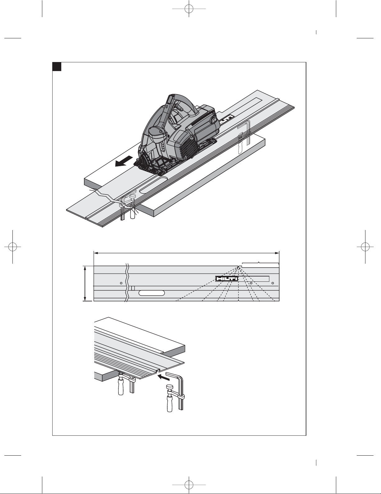
7.8 Using the saw on the guide rail 8
7.8.1 Longitudinal cuts at 0 °
Place the saw on the guide rail so that the rib fits into
the groove in the base plate.
7.8.2 Longitudinal cuts at up to 50 °
Guide the saw so that the outer edge of the base plate
runs along the rib on the guide rail. The saw blade
will otherwise come into contact with the guide rail.
7.8.3 Cuts at an angle across the surface of the
workpiece
NOTE
The cutting angle indicated is the angle of deviation
from a straight, right-angled cut.
1. Position the guide rail with the zero mark at the
edge of the workpiece and then pivot the rail until
the desired angle shown on the angle scale is
opposite the zero mark.
2. Use the two screw clamps to secure the guide
rail.
7.9 Using the saw with a dust and chip removal
system 9
NOTE
The hand-held circular saw is equipped with a hose
connector suitable for use with conventional vacuum
cleaner hoses with a diameter of 27 mm.
CAUTION
Dusts are hazardous to the health and can cause
respiratory or skin diseases and allergic reactions.
WARNING
Certain dusts are considered to be carcinogenic
(cause cancer). These include mineral dust as well as
oak and/or beech wood dust, particularly in conjunction with additional substances used for the treatment
of wood (chromate, wood preservatives).
CAUTION
Wherever possible, use a suitable mobile vacuum
dust removal system such as the WVC 40ತM(wood)
or VCU 40ತM (wood and mineral materials) for the
application concerned. Use a respiratory protector of
the P2 filter class with half-mask facepiece if no dust
removal system is available or its use is impossible.
In addition, to keep the concentration of dust low,
always ensure good ventilation.
CAUTION
Commercial and industrial users must consult the
responsible trade association to clarify the situation
regarding special requirements applicable to working
on other materials.
7.10 Using the saw without a dust and chip
removal system
NOTE
Thepowertoolcanalsobeusedwithapush-onchip
deflector nozzle.
Turn the nozzle to the desired direction of ejection so
that the chips and dust are deflected away from you.
28
Page 18

8. Care and maintenance
CAUTION
Before beginning cleaning, remove the battery from
the power tool in order to prevent unintentional
starting.
8.1 Care of insert tools
Clean off dirt and dust deposits adhering to the insert
tools and protect them from corrosion by wiping the
insert tools from time to time with an oil-soaked rag.
8.2 Care of the power tool
The outer casing of the power tool is made from
impact-resistant plastic. Sections of the grip are made
from a synthetic rubber material.
Never operate the power tool when the ventilation
slots are blocked. Clean the ventilation slots carefully
using a dry brush. Do not permit foreign objects to
enter the interior of the power tool. Clean the outside
of the power tool at regular intervals with a slightly
damp cloth. Do not use a spray, steam pressure
cleaning equipment or running water for cleaning.
This may negatively affect the electrical safety of the
power tool. Always keep the grip surfaces of the
power tool free from oil and grease. Do not use
cleaning agents which contain silicone.
8.3 Care of the NiCd battery
Keep the electrical contacts free from dust, oil and
grease. If necessary, use a clean cloth to clean the
contact surfaces. The battery must be recharged as
soon as the power tool’s performance drops noticeably or when the deep discharge prevention system
becomes active.
NOTE
Please refer to the operating instructions for the
charger for further information about charging the
battery.
8.4 Care of the Li-ion battery
Avoid entrance of moisture.
Charge the battery fully before using it for the first
time.
In order to achieve maximum battery life, stop discharging the battery as soon as a significant drop in
performance is noticed.
NOTE
If use of the power tool continues, further battery
discharge will be stopped automatically before the
battery cells suffer damage.
Charge the battery with the Hilti charger approved for
use with Li-ion batteries.
NOTE
- A conditioning charge (as is required with NiCd or
NiMH batteries) is not necessary.
- Interruption of the charging procedure has no neg-
ative effect on battery life.
- Charging can be started at any time with no negative
effect battery life. There is no memory effect (as with
NiCd or NiMH batteries).
- For best results, batteries should be stored fully
charged in a cool dry place. Avoid charging the battery
in places subject to high ambient temperatures (e.g.
at a window) as this has an adverse effect on battery
life and increases the rate of self-discharge.
- If the battery no longer reaches full charge, it may
have lost capacity due to aging or overstressing. It
is possible to continue working with a battery in this
condition but it should be replaced in good time.
8.5 Maintenance
WARNING
Repairs to the electrical section of the power tool
may be carried out only by trained electrical specialists.
Check all external parts of the power tool for damage
at regular intervals and check that all controls operate
faultlessly. Do not operate the power tool if parts
are damaged or when the controls do not function
faultlessly. Have the power tool repaired by Hilti
Service.
8.6 Checking the power tool after care and
maintenance
After carrying out care and maintenance work on
the power tool, check that all protective and safety
devices are fitted and that they function faultlessly.
en
29
Page 19

9. Troubleshooting
Fault Possible cause Remedy
The power tool
doesn’t run.
en
The on / off switch
can’t be pressed,
i.e. the switch is
locked.
Running speed
suddenly drops
considerably.
The battery runs
down more quickly
than usual.
The power tool
doesn’t restart by
itself after the saw
blade has stalled.
The battery doesn’t
engage with an
audible double
click.
The tool or the
battery become
very warm.
The battery is discharged or fitted
incorrectly.
Electrical fault. Remove the battery from the power tool
The battery is discharged/hot. Deep discharge prevention / the elec-
Not a fault (safety function).
The battery is discharged or excessive
working pressure is applied to the power
tool.
Battery condition is not optimal.
The deep discharge prevention system
switches off afterthe blade stalls a second
time.
The retaining lugs on the battery are dirty.
Electrical fault. Switch the power tool off immediately,
The power tool has been overloaded
(application limits exceeded).
Thebatteryneedstobechargedor,
respectively, it must be heard to engage
with a double click.
and contact Hilti.
tronics switch off. Fit the battery into the
charger.
Press the switch-on interlock.
Change the battery and recharge the
discharged battery. Reduce the working
pressure applied to the power tool.
Only NiCd batteries should be given a
conditioning charge. (Please refer to the
operating instructions for the charger.)
Press the switch-on interlock and the
control switch again.
Clean the retaining lugs and check that
the battery engages securely. Contact
Hilti Service if the problem persists.
remove the battery and contact Hilti
Service.
Use the right power tool for the job (don’t
use a low-powered tool for heavy work).
10. Disposal
CAUTION
Improper disposal of the equipment may have serious consequences: The burning of plastic components
generates toxic fumes which may present a health hazard. Batteries may explode if damaged or exposed to
very high temperatures, causing poisoning, burns, acid burns or environmental pollution. Careless disposal
may permit unauthorized and improper use of the equipment. This may result in serious personal injury, injury
to third parties and pollution of the environment.
CAUTION
Dispose of defective batteries without delay. Keep them out of reach of children. Do not attempt to open or
dismantle batteries and do not dispose of them by incineration.
30
Page 20

CAUTION
Dispose of the batteries in accordance with national regulations or return them to Hilti.
Most of the materials from which Hilti tools or machines are manufactured can be recycled. The materials must
be correctly separated before they can be recycled. In many countries, Hilti has already made arrangements
for taking back your old tools for recycling. Please ask your Hilti customer service department or Hilti
representative for further information.
For EC countries only
Disposal of electric tools together with household waste is not permissible.
In observance of European Directive 2002/96/EC on waste electrical and electronic equipment
and its implementation in accordance with national law, electric tools that have reached the end
of their life must be collected separately and returned to an environmentally compatible recycling
facility.
11. Manufacturer’s warranty - tools
Hilti warrants that the tool supplied is free of defects
in material and workmanship. This warranty is valid
so long as the tool is operated and handled correctly,
cleaned and serviced properly and in accordance with
the Hilti Operating Instructions, and the technical
system is maintained. This means that only original
Hilti consumables, components and spare parts may
be used in the tool.
This warranty provides the free-of-charge repair or
replacement of defective parts only over the entire
lifespan of the tool. Parts requiring repair or replacement as a result of normal wear and tear are not
covered by this warranty.
Additional claims are excluded, unless stringent national rules prohibit such exclusion. In particular,
Hilti is not obligated for direct, indirect, incidental
or consequential damages, losses or expenses in
connection with, or by reason of, the use of, or
inability to use the tool for any purpose. Implied
warranties of merchantability or fitness for a particular purpose are specifically excluded.
For repair or replacement, send the tool or related
parts immediately upon discovery of the defect to
the address of the local Hilti marketing organization
provided.
This constitutes Hilti's entire obligation with regard
to warranty and supersedes all prior or contemporaneous comments and oral or written agreements
concerning warranties.
en
31
Page 21

12. EC declaration of conformity
Designation:
Type:
Year of design:
en
We declare, on our sole responsibility, that this
product complies with the following directives and
standards: 89/336/EEC, 98/37/EC, 91/157/EEC,
93/86/EEC, EN 60745ತ1, EN 60745ತ2ತ5, EN 55014ತ1,
EN 55014ತ2.
Cordless circular saw
WSC 70ತA36 /
WSC 55ತA24
2006
Hilti Corporation
keine Unterschrift keine Unterschrift
erfolgt erst erfolgt er st
nach Abnahme nach Abnahme
05 2006 05 2006
32
Page 22

00_Cover_WSC70_A36_P1.qxd 1.6.2006 10:23 Seite 3
Hilti Corporation
LI-9494 Schaan
Tel.: +423 / 234 2111
Fax: +423/234 29 65
www.hilti.com
Hilti = registered trademark of Hilti Corp., Schaan W 3125 0606 00-Pos.1 1 Printed in Liechtenstein © 2006
Right of technical and programme changes reserved S. E. & O.
236297 / A
*236297*
236297
 Loading...