

Page 1

WSC 267-E
Operating instructions en
Mode d’emploi fr
Manual de instrucciones es
Printed: 07.07.2013 | Doc-Nr: PUB / 5071326 / 000 / 00
Page 2
1
1
2
9
3
21
4
9
19
13
11
14
12
5
20
6
15
21
17
16
6
11
7
18
8
Printed: 07.07.2013 | Doc-Nr: PUB / 5071326 / 000 / 00
4
Page 3

Este producto està contenido en la list UL y tiene la certificación CSA
Ce produit est homologué UL et certifié CSA
Printed: 07.07.2013 | Doc-Nr: PUB / 5071326 / 000 / 00
This product is UL listed and CSA certified
Page 4
2
3
5
2
Printed: 07.07.2013 | Doc-Nr: PUB / 5071326 / 000 / 00
1
6
4
3
Page 5
4
1
2
55 in (1400 mm)
9
5
7
7.8 in (200 mm)
3
Printed: 07.07.2013 | Doc-Nr: PUB / 5071326 / 000 / 00
10
60° 45° 45°30° 30°22.5° 22.5°0°
6
4
8
2
Page 6

WSC 267-E hand-held circular saw
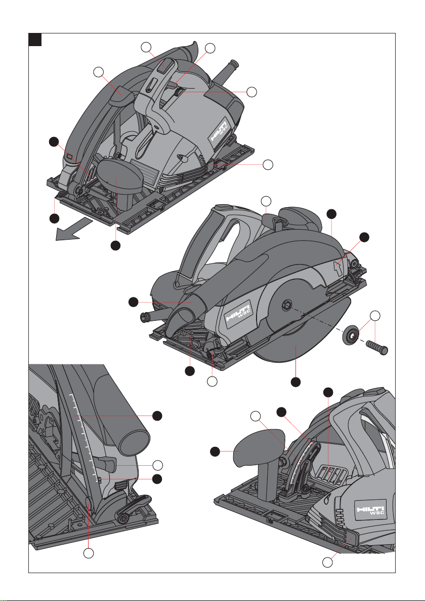
Operating controls and parts of the WSC267-E
It is essential that the operating
instructions are read before the
tool is operated for the first time.
Always keep these operating
instructions together with the tool.
Ensure that the operating
instructions are with the tool when
it is given to other persons.
햲 Switch interlock
햳 On / off switch
햴 Speed pre-selection thumbwheel
햵 Clamping lever
햶 Clamping screw and clamping flange
햷 Cutting angle adjustment clamp
햸 Cutting depth locking lever
햹 Cutting depth selector
햺 Manual control for pivoting guard
Parts of the WSC 267-E
쐈 Auxiliary grip
쐉 Pivoting chip ejector nozzle
씈 Chip ejector cover
씉 Blade guard
씊 Pivoting guard
씋 Cutting angle scale
씌 Cutting depth scale
씍 Pre-set cutting depth
씎 Cutting line indicator
씏 Hex. socket wrench
쏹
21
Viewing grill
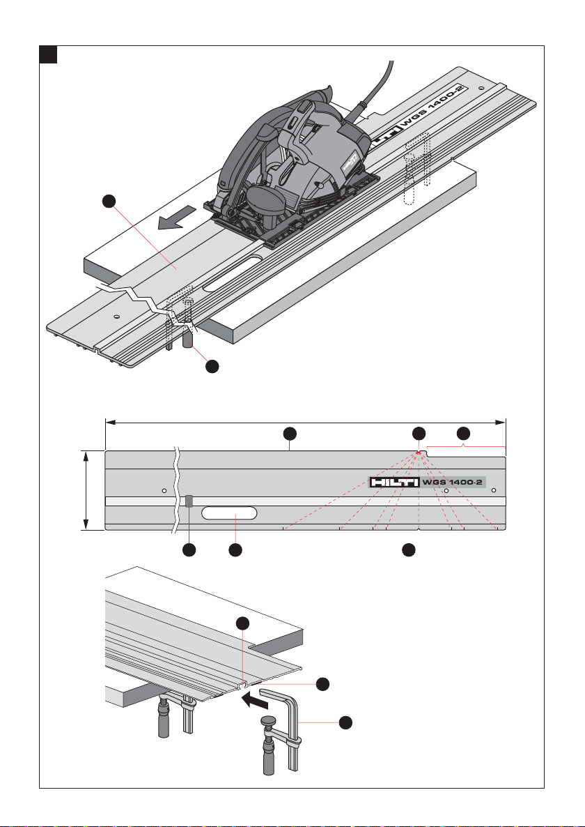
Parts of the WGS 1400-2 guide rail (Accessories)
쐃 Guide rail
쐇 Screw clamps (accessories)
쐋 Stop
쐏 Channel for screw clamps
쐄 0° indicator mark
쐂 Lateral cutting angle scale (up to 60°)
쐆 Saw positioning / starting section
쐊 Non-slip strips
쐎 Guide rail cutting edge
쐅 Grip opening
Contents Page
1. General information 2
2. Technical data 2
3. General safety rules 3
4. Specific safety ruels 4
5. Additional specific safety rules and symbols 5
6. Functional description 6
7. Assembly 6
8. Operation 6
9. Care and maintenance 8
10. Accessories 9
11. Manufacturer's warranty – tools 10
12. Disposal 11
13. Troubleshooting 11
Printed: 07.07.2013 | Doc-Nr: PUB / 5071326 / 000 / 00
Parts of the WPG 265 parallel guide (Accessory)
Parallel guide
Hex. screw
Pressure spring
Clamping piece
Hex. nut
Clamping lever
1
Page 7

1. General information
1.1 Indication of danger
-WARNING-
The word WARNING is used to draw attention to a potentially dangerous situation which could lead to severe
personal injury or death.
-CAUTION-
This word is used to draw attention to a potentially dangerous situation which could lead to minor personal injury
or damage to the equipment or other property.
1.2 Pictograms
Warning signs
Symbols
The numbers refer to the illustrations. The illustrations can be found on the fold-out cover pages. Keep
these pages open while you read the operating instructions.
“The tool” referred to in these operating instructions is
always the WSC 267-E circular saw.
Location of identification data on the tool
The type designation and serial number can be found
on the type plate of the tool. Make a note of this data in
your operating instructions and always refer to it when
making an enquiry to your Hilti representative or service department.
Type:
General
warning
Warning:
electricity
Read the operat-
ing instructions
before use.
Serial no:
Obligation signs
Wear eye
protection
Wear breathing
protection
Wear ear
protection
Wear
protective
gloves
2. Technical data WSC267-E (constant-speed Electronics)
Rated power: 1500 W
Power output: 800 W
Nominal voltage: ~120 V AC
Nominal current input: 13.5 A
Spindle speed under no load: 4300 r.p.m. (setting 6)
Spindle speed under load (settings1–6): 1900–3900 r.p.m.
Cutting depth at 0°: 0–67 mm 0–25/8″
Cutting depth at 45°: 0–54 mm 0–2″
Angular adjustment: 0°–45°
Saw blade specification:
– Maximum saw blade diameter: 184 mm 7
– Minimum saw blade diameter: 165 mm 6
– Blade mounting hole diameter:
– Steel disc core thickness: 1.2–1.5 mm
– Maximum kerf width: 1.9–2.4 mm
– Minimum rated blade speed when idling (n): n ≥ 6500 r.p.m
Dust extraction connector internal dia.: 35 mm 13/8″
Machine weight: 4.5 kg 10 Pounds
Electrical protection class: Z / II (double insulated)
Right of technical changes reserved.
1
/4″
1
/2″
5
/8″
3
/64″–1/16″
1
/16″–3/32″
2
Printed: 07.07.2013 | Doc-Nr: PUB / 5071326 / 000 / 00
Page 8

3. General safety rules
1. WARNING!
Read and understand all instructions.
Failure to follow all instructions listed below may
result in electric shock, fire and/or serious personal
injury.
SAVE THESE INSTRUCTIONS
2. Work Area
2.1 Keep your work area clean and well lit. Cluttered benches and dark areas invite accidents.
2.2 Do not operate power tools in explosive
atmospheres, such as in the presence of flammable liquids, gases, or dust. Power tools create
sparks which may ignite the dust or fumes.
2.3 Keep bystanders, children and visitors away
while operating a power tool. Distractions can
cause you to lose control.
tention while operating power tools may result in
serious personal injury.
4.2 Dress properly. Do not wear loose clothing or
jewelry. Contain long hair. Keep your hair, clothing, and gloves away from moving parts. Loose
clothes, jewelry, or long hair can be caught in moving parts.
4.3 Avoid accidental starting. Be sure switch is off
before plugging in. Carrying tools with your finger
on the switch or plugging in tools that have the
switch on invites accidents.
4.4 Remove adjusting keys or wrenches before
turning the tool on. A wrench or a key that is left
attached to a rotating part of the tool may result in
personal injury.
4.5 Do not overreach. Keep proper footing and bal-
ance at all times. Proper footing and balance
enables better control of the tool in unexpected situations.
3. Electrical Safety
3.1 Double Insulated tools are equipped with a polarized plug (one blade is wider than the other.) This
plug will fit in a polarized outlet only one way. If the
plug does not fit fully in the outlet, reverse the plug.
If it still does not fit, contact a qualified electrician to
install a polarized outlet. Do not change the plug in
any way. Double Insulation Z eliminates the need for
the three wire grounded power cord and grounded power
supply system. Applicable only to Class II tools.
3.2 Avoid body contact with grounded surfaces
such as pipes, radiators, ranges and refrigerators.
There is an increased risk of electric shock if your
body is grounded.
3.3 Do not expose power tools to rain or wet con-
ditions. Water entering a power tool will increase
the risk of electric shock.
3.4 Do not abuse the cord. Never use the cord to
carry the tools or pull the plug from an outlet.
Keep cord away from heat, oil, sharp edges or
moving parts. Replace damaged cords immediately. Damaged cords increase the risk of electric
shock.
3.5 When operating a power tool outside, use an
outdoor extension cord marked «W-A» or «W».
These cords are rated for outdoor use and reduce
the risk of electric shock.
4. Personal Safety
4.1 Stay alert, watch what you are doing and use
common sense when operating a power tool. Do
not use a tool while tired or under the influence of
drugs, alcohol, or medication. A moment of inat-
4.6 Use safety equipment. Always wear eye protection. Dust mask, non-skid safety shoes, hard hat
or hearing protection must be used for appropriate
conditions.
5. Tool Use and Care
5.1 Use clamps or other practical way to secure
and support the workpiece to a stable platform.
Holding the work by hand or against your body is
unstable and may lead to loss of control.
5.2 Do not force tool. Use the correct tool for your
application. The correct tool will do the job better
and safer at the rate for which it is designed.
5.3 Do not use tool if the switch does not turn it on
or off. Any tool that cannot be controlled with the
switch is dangerous and must be repaired.
5.4 Disconnect the plug from the power source be-
fore making any adjustments, changing accessories, or storing the tool. Such preventive safety
measures reduce the risk of starting the tool accidentally.
5.5 Store idle tools out of reach of children and
other untrained persons. Tools are dangerous in
the hands of untrained users.
5.6 Maintain tools with care. Keep cutting tools
sharp and clean. Properly maintained tools with
sharp cutting edges are less likely to bind and are
easier to control.
5.7 Check for misalignment or binding of moving
parts, breakage of parts and any other condition
that may affect the tools operation. If damaged,
Printed: 07.07.2013 | Doc-Nr: PUB / 5071326 / 000 / 00
3
Page 9

have the tool serviced before using. Many accidents are caused by poorly maintained tools.
5.8 Use only accessories that are recommended
by the manufacturer for your model. Accessories
that may be suitable for one tool may become hazardous when used on another tool.
6. Service
6.1 Tool service must be performed only by qualified repair personnel. Service or maintenance per-
formed by unqualified personnel could result in a risk
of injury.
6.2 When servicing a tool, use only identical
replacement parts. Follow instructions in the Maintenance section of this manual. Use of unauthorized
parts or failure to follow Maintenance Instructions
may create a risk of electric shock or injury.
4. Specific safety rules
G DANGER! Keep hands away from cutting area and
blade. Keep your second hand on auxiliary handle, or
motor housing. If both hands are holding the saw, they
cannot be cut by the blade.
G Keep your body positioned to either side of the saw
blade, but not in line with the saw blade. KICKBACK
could cause the saw to jump backwards (see ”Causes
and Operator Prevention of Kickback”).
G Do not reach underneath the work. The guard can
not protect you from the blade below the work.
G Check lower guard for proper closing before each
use. Do not operate saw if lower guard does not move
freely and close instantly. Never clamp or tie the lower guard into the open position. If saw is accidentally
dropped, lower guard may be bent. Raise the lower guard
with the Retracting Handle and make sure it moves freely
and does not touch the blade or any other part, in all
angles and depths of cut.
G Check the operation and condition of the lower guard
spring. If the guard and the spring are not operating
properly, they must be serviced before use. Lower
guard may operate sluggishly due to damaged parts,
gummy deposits, or a buildup of debris.
G Lower guard should be retracted manually only for
special cuts such as ”Pocket Cuts” and ”Compound
Cuts”. Raise lower guard by Retracting Handle. As
soon as blade enters the material, lower guard must
be released. For all other sawing, the lower guard should
operate automatically.
G Always observe that the lower guard is covering the
blade before placing saw down on bench or floor. An
unprotected, coasting blade will cause the saw to walk
backwards, cutting whatever is in its path. Be aware of
the time it takes for the blade to stop after switch is
released.
4
Printed: 07.07.2013 | Doc-Nr: PUB / 5071326 / 000 / 00
G NEVER hold piece being cut in your hands or across
your leg. It is important to support the work properly to
minimize body exposure, blade binding or loss of control.
G Hold tool by insulated gripping surfaces when performing an operation where the cutting tool may contact hidden wiring or its own cord. Contact with a ”live”
wire also make exposed metal parts of the tool ”live” and
shock the operator.
G When ripping always use a rip fence or straight edge
guide. This improves the accuracy of cut and reduces
the chance for blade binding.
G Always use blades with correct size and shape (diamond vs. round) arbor holes. Blades that do not match
the mounting hardware of the saw will run eccentrically, causing loss of control.
G Never use damaged or incorrect blade washers or
bolts. The blade washers and bolt were specially designed
for your saw, for optimum performance and safety of
operation.
Causes and Operator Prevention of Kickback:
– Kickback is a sudden reaction to a pinched, bound or
misaligned saw blade, causing an uncontrolled saw
to lift up and out of workpiece toward the operator.
– When the blade is pinched or bound tightly by the kerf
closing down, the blade stalls and the motor reaction
drives the unit rapidly back toward the operator.
– If the blade becomes twisted or misaligned in the cut,
the teeth at the black edge of the blade can dig into the
top surface of the wood causing the blade to climb out
of the kerf and jump back toward operator.
– Kickback is the result of tool misuse and/or incorrect
operating procedures or conditions and can be avoided by taking proper precautions as given below:
G Maintain a firm grip with both hands on the saw and
position your body and arm to allow you to resist KICKBACK forces. KICKBACK forces can be controlled by the
operator, if proper precautions are taken.
G When blade is binding, or when interrupting a cut
for any reason, release the trigger and hold the saw
motionless in the material until the blade comes to a
complete stop. Never attempt to remove the saw from
the work or pull the saw backward while the blade is
in motion or KICKBACK may occur. Investigate and take
corrective actions to eliminate the cause of blade binding.
G When restarting a saw in the workpiece, center the
saw blade in the kerf and check that saw teeth are not
engaged into the material. If saw blade is binding, it
may walk up or KICKBACK from the workpiece as the
saw is restarted.
G Support large panels to minimize the risk of blade
pinching and KICKBACK.
under their own weight. Supports must be placed under
the panel on both sides, near the line of cut and near the
edge of the panel.
G Do not use dull or damaged blade. Unsharpened or
improperly set blades produce narrow kerf causing excessive friction, blade binding and KICKBACK.
Large panels tend to sage
Page 10

G Blade depth and bevel adjusting locking levers must
be tight and secure before making cut. If blade adjust-
ment shifts while cutting, it may cause binding and KICKBACK.
G Use extra caution when making a ”Pocket Cut” into
existing walls or other blind areas. The protruding blade
may cut objects that can cause KICKBACK.
5. Additional specific safety rules and
symbols
Basic information concerning safety
In addition to the information relevant to safety given in
each of the sections of these operating instructions, the
following points must be strictly observed at all times:
Correct use
G The tool is designed for cutting through, cutting grooves
and cutting into wood, wood-like materials, plaster- and
cement-bonded fibre materials (no asbestos) and plastics.
G The working environment may be on a construction
site or in a workshop and may consist of renovation, conversion or new building work.
G The tool may be operated only when connected to a
power supply providing a voltage and frequency in compliance with the information given on the type plate.
Incorrect use (misuse)
G Sawing metals is not permissible.
G The tool may be operated only when held and guided
by both hands.
G No changes or modifications may be made to the tool
and its protective equipment and it must not be manipulated in any way other than as described in the operating instructions.
G To avoid the risk of injury, always use only Hilti original accessories.
G Do not use the tool for cutting branches off trees or
for cutting logs.
G Avoid cutting nails. Inspect for and remove all nails
from workpiece before cutting.
Observe the information given in the operating instructions concerning operation, care and maintenance.
State of the art
The tool is designed and manufactured in accordance
with state of the art technology and thus provides a high
level of operating safety. Nevertheless, the tool and its
accessories may present hazards when used incorrectly by untrained personnel or when misused.
Take the necessary precautions to make the workplace
safe
G Take care to avoid tripping over the supply cord or
extraction hose.
G Whenthetoolisinuse,alwaysguidethesupplycord
and extraction hose away from the tool to the rear.
G Keep the area above and below the cutting line free of
obstacles.
G Place the wider portion of the tool guide plate on the
part of the workpiece which is supported, not on the part
that will drop when the cut is made. If the workpiece is
small, clamp it down before cutting.
G Never attempt to clamp the tool down and move the
workpiece into the tool.
General hazards presented by the tool
G The tool may be used only for the purposes for which
it was designed, when in faultless condition and when
used correctly.
G Keep the grips clean, dry and free of oil and grease.
G Always hold the tool securely in both hands.
G Never place your hands in front of the circular saw
blade.
G Always switch on the tool and allow it to reach full
operating speed before bringing it into contact with the
workpiece.
G Operate the tool only together with the applicable protective equipment.
G The rotating saw blade must not be touched while sawing. The part of the saw blade projecting below the workpiece, the clamping flange and the clamping screw must
not be touched.
G When not in use, the tool must be locked away in a
dry place, out of reach of children.
G Do not allow the saw to brush against your leg or other part of your body. The pivoting guard could catch on
your clothing and expose the blade.
G Proposition 65 warning: This product contains or produces an exposure to chemicals known to the State of
California to cause cancer and birth defects (or othe reproductive harm).
G Children must be instructed not to play with the tool.
G The tool is not intended for use by children, by debil-
itated persons or those who have received no instruction or training.
G WARNING: Some dust created by grinding, sanding, cutting and drilling contains chemicals known to
cause cancer, birth defects, infertility or other reproductive harm; or serious and permanent respiratory or
other injury. Some examples of these chemicals are:
lead from lead-based paints, crystalline silica from bricks,
concrete and other masonry products and natural stone,
arsenic and chromium from chemically-treated lumber.
Your risk from these exposures varies, depending on
how often you do this type of work. To reduce exposure
to these chemicals, the operator and bystanders should
work in a well-ventilated area, work with approved
safety equipment, such as respiratory protection appropriate for the type of dust generated, and designed to
Printed: 07.07.2013 | Doc-Nr: PUB / 5071326 / 000 / 00
5
Page 11

filter out microscopic particles and direct dust away
from the face and body. Avoid prolonged contact with
dust. Wear protective clothing and wash exposed areas
with soap and water. Allowing dust to get into your
mouth, eyes, or to remain on your skin may promote
absorption of harmful chemicals.
Electrical
G Concealed electric cables or gas and water pipes present a serious hazard if damaged while you are working. Accordingly, check the area in which you are working beforehand, e.g. by using a metal detector.
G External metal parts of the tool may become live, for
example, when the saw cuts inadvertently into an electric cable.
G Do not touch the supply cord if it has become damaged while working. Disconnect the supply cord plug
from the mains socket immediately.
G Dust or dampness on the surface of the tool make it
slippery and difficult to hold and may, under unfavourable
conditions, present a risk of electric shock.
Conditions to be fulfilled by the user
G The tool is designed for professional use.
Personal protective equipment
Protective devices
Do not switch on the tool when the saw blade, the blade
guard, the pivoting guard are not fitted correctly.
G The pivoting guard must be able to move freely. It must
not be fixed in an open position.
Symbols used on the tool:
V volts n
~ alternating current /min rev olution sp er minute
no load speed
0
Hz hertz ∅ diameter
A amperes Z double insulated
7. Assembly
-CAUTION-
I The cutting edges of the saw blade
are sharp.
I The cutting edges may present a risk
of injury.
I Wear protective gloves.
It is essential that the safety precautions printed in these
operating instructions are read and observed.
G Disconnect the plug from the mains socket.
G Check that the saw blade is mounted securely and that
it runs freely.
G Check all safety equipment for correct functionality.
If extension cords are used: only extension cords of a
type approved for the intended use and of adequate cross
section may be used. Failure to observe this point may
result in reduced performance of the tool and over heating of the cord. Check the extension cord for damage at
regular intervals. Damaged extension cords must be
replaced.
Recommended minimum cross sections and max. cord
lengths:
Extension Cord Table
Volts Total Length of Cord inFeet
120 V 0–25 26– 50 51–100 101–150
240 V 0–50 51–100 101–200 201–300
Ampere Rating AWG
More Than Not More Than
0 6 18 16 16 14
610 18161412
10 12 16 16 14 12
12 16 14 12 Not recommended
Extension cords for outdoor use
For outdoor work use only extension cords approved and
correspondingly marked as suitable for outdoor use.
Pay attention at all times
Always concentrate on the job. Proceed carefully and do
not use the tool if you are distracted from your work.
6. Functional description
The WSC 267-E is an electrically powered hand-held tool
designed for the sawing of wood, plastics and composite
materials by professional users.
The following items are supplied: power tool with saw
blade, operating instructions, pivoting chip ejector and
toolbox.
6
Printed: 07.07.2013 | Doc-Nr: PUB / 5071326 / 000 / 00
8. Operation
-CAUTION-
I The cutting edges of the saw blade
are sharp.
I The cutting edges may present a risk
of injury.
I Wear protective gloves.
Page 12

-CAUTION-
I The sawing operation creates up dust
and wood chips.
I The dust and wood chips may be
harmful to the eyes and lungs.
I Wear protective goggles and respi-
ratory protection.
-CAUTION-
I Operation of the tool creates noise.
I Noise may damage the hearing.
I Wear ear protection.
System
G Always direct the tool away from the body when working.
G Lay the tool down only when the pivoting guard is
closed.
G Do not work overhead with the tool.
G Do not brake the saw blade by applying lateral pres-
sure.
G Use only saw blades in good condition in order to
achieve good cutting performance and to minimise wear
and tear on the tool.
G Use of the following is not permissible:
- Blunt saw blades
- Unsuitable saw blades
- Cracked saw blades
- Cutting discs (designed for use with angle grinders
etc.)
- Saw blades made from high-alloyed, high-speed
steel (HSS steel)
G Always disconnect the supply cord plug from the mains
socket before disassembling or adjusting the tool.
G Do not switch the tool on before it has been brought
into position where the cut is to be made.
G Do not overload the tool.
Cutting along a line
A cutting line indicator (0° / 22.5° / 45°), is located on
the front section of the baseplate of the tool. This permits
precise cuts to be made at the selected cutting angle. The
viewing grill provides a better view of the cutting line,
thus making it easier to check the progress of the cut.
If required, the cutting depth can be pre-set to any value
within the 0–65 mm (0–2
Best results will be obtained when the saw blade projects
approx. 5–10 mm (
5
/8″) depth range.
1
/4–1/2″) beyond the underside of the
workpiece.
G Check that the control switch on the tool is in the OFF
position.
G Connect the supply cord plug to the mains socket.
G Position the tool with the baseplate on the workpiece
so that the saw blade is not in contact with the workpiece.
G Switch the tool on by pressing the switch interlock
and the on/off switch.
G Guide the saw at a suitable speed through the workpiece while following the cutting line.
Mitre cuts
Adjusting the cutting angle
G Release both cutting angle clamping levers.
G Pivot the mechanism until the desired cutting angle
of 0°–45° is indicated by the cutting angle scale.
G Retighten both clamping levers.
G Make the cut while observing the cutting line indica-
tor at the front section of the baseplate.
Returning the saw to the 0° position
G Clean the baseplate to remove wood chips or other
foreign material from the pivoting section before returning the saw to its original position.
Plunge cutting
To reduce the risk of kick-back when starting a plunge
cut, a wooden batten or similar stop should be securely
fastened to the workpiece behind the rear of the tool
baseplate.
When cutting to the full depth, the length of the cut can
be checked at the plunge cut marks located on the baseplate.
G Check that the switch on the tool is in the OFF position.
G Connect the supply cord plug to the mains socket.
G Place the tool on a suitable surface.
G Release the cutting depth locking lever.
G Lift the tool by the grip. Use the pivoting guard man-
ual control to open the pivoting guard.
G Position the tool at the point where the plunge cut is
to be made.
G Switch on the tool by pressing the switch interlock
and the on / off switch and then plunge the blade into the
workpiece carefully until the cut has been made to the
desired length.
Setting the cutting depth
The cutting depth can be set to any value within the 0–
65 mm (0–2
5
/8″) range.
G Place the tool on a suitable suface.
G Release the cutting depth adjusting lever.
G Lift the tool as far as it will go and lock in position at
the maximum height.
G Adjust the cutting depth by releasing the screw, moving along the scale to the desired position and then fixing the cutting depth at this point.
G Release the cutting depth locking lever and return the
tool to the pre-set height.
Except when plunge cutting it is advisable, for safety reasons, to lock the cutting depth at this height. Nevertheless, as deviations may occur due to various factors (e.g.
worn or resharpened saw blade etc.), it is recommended that the cutting depth is checked again exactly before
Printed: 07.07.2013 | Doc-Nr: PUB / 5071326 / 000 / 00
7
Page 13

beginning sawing by measuring the projection of the saw
blade from the baseplate.
Constant speed electronics / speed pre-selection
The WSC 267-E is equipped with constant speed electronics.
The speed regulator can be used to adjust the speed of
the saw blade to any value within the 2200–4300 r.p.m.
range. The numbers on the speed regulator represent the
following approximate saw blade speeds:
1 2200 r .p.m.
2 2600 r .p.m.
3 3000 r .p.m.
4 3500 r .p.m.
5 3900 r .p.m.
6 4300 r .p.m.
The built-in constant speed electronics maintain the preselected speed at an almost constant level even when the
tool is under load. The recommended speeds and information concerning choice of the correct saw blade can
be found in the product information and corresponding
table of applications.
Smooth starting
The tool is equipped with a starting current limitation
device which ensures optimum working comfort. The
tool thus starts and runs up to speed without an unpleasant jolt.
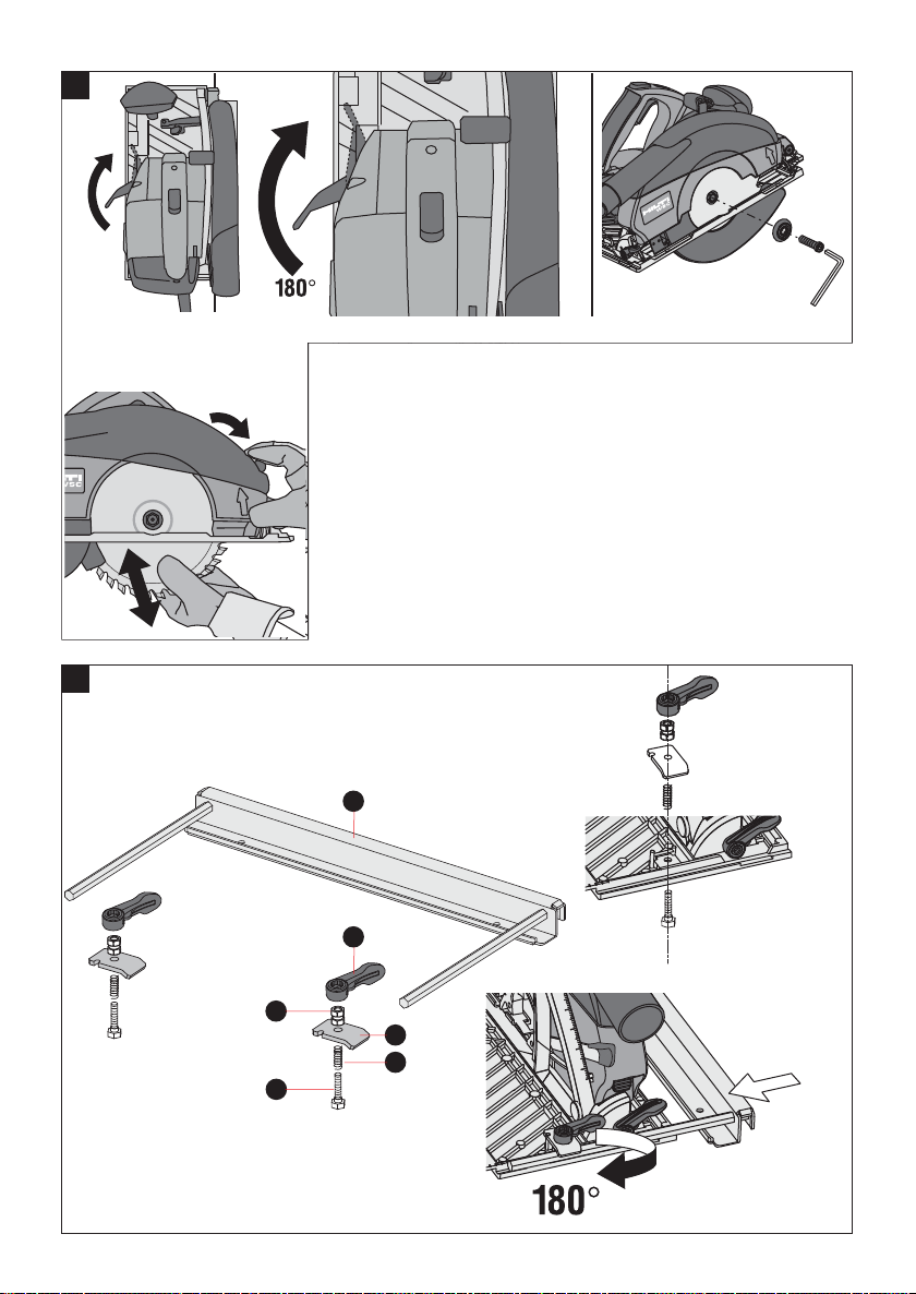
Changing saw blades without the use of tools
-CAUTION-
I The saw blade becomes hot when
used for long periods.
I There is a risk of burning if the blade
is touched.
I Wear protective gloves.
G Disconnect the supply cord plug from the mains socket.
G Place the tool on its baseplate, on a suitable surface.
G Open the clamping lever as far as it will go.
G Tip the tool onto the supporting rib provided at the
motor side, so that the saw blade faces upwards and is
easily accessible.
G Release the clamping sccccrew and clamping flange
by turning in a counter-clockwise direction.
G Use the manual control to swing the pivoting guard
back and remove the saw blade.
G Clean the saw blade contact surfaces to remove wood
chips and other foreign material.
G Check again that the data for the saw blade complies
with the information given in these operating instructions.
G The saw blade must meet the specification for the tool
with regard to spindle speed, spindle size and shape, disc
core thickness, kerf width and blade diameter.
Use of other saw blades is not permissible.
G When fitting the new saw blade, take care to ensure
that the direction of rotation arrow on the saw blade corresponds to the direction of rotation arrow on the guard.
G Check that the saw blade is seated correctly.
G Use the wrench included to tighten the clamping screw
and flange securely in a clockwise direction.
G Stand the tool on its baseplate.
G Bring the clamping lever back to its original position.
The following design aspects were incorporated in the
tool for more safety when changing saw blades:
G The clamping lever cannot be opened when the switch
interlock is depressed, i.e. when the tool is running.
G The switch interlock cannot be depressed when the
clamping lever is open, i.e. the tool cannot be started.
G Do not attempt to overcome the interlock by using
tools or applying excessive force.
9. Care and maintenance
Care
G Used saw blades should be cleaned to remove resin
deposits at regular intervals as clean blades achieve a
much higher cutting performance. Resin deposits can
be removed by placing the saw blades in a bath of petroleum (paraffin, kerosene) or commercially available resin
remover.
G Carbide-tipped circular saw blades
must no longer be used when the
remaining height or thickness of the
brazed-on tips is less than 1 mm
1
(
/16″).
G The tool was lubricated adequately when it was manufactured. After long periods of heavy use, it is recommended that the tool is inspected at a Hilti repair center.
This will increase the life expectancy of the tool and avoid
unnecessary repair costs.
G Repairs to the electrical section of the tool may be carried out only by a trained electrical specialist.
CAUTION
Keep the power tool, especially its grip surfaces, clean
and free from oil and grease. Do not use cleaning
agents which contain silicone.
The outer casing of the power tool is made from impactresistant plastic. Sections of the grip are made from a
synthetic rubber material.
Never operate the power tool when the ventilation slots
are blocked. Clean the ventilation slots carefully using
a dry brush. Do not permit foreign objects to enter the
interior of the power tool. Clean the outside of the power tool at regular intervals with a slightly damp cloth. Do
1/16″
1/16″
8
Printed: 07.07.2013 | Doc-Nr: PUB / 5071326 / 000 / 00
Page 14

not use a spray, steam pressure cleaning equipment or
running water for cleaning. This may negatively affect
the electrical safety of the power tool.
Maintenance
Regularly check all external parts of the tool for damage
and check that all controls operate faultessly. Don’t operate the tool when parts are damaged or when the controls do not function faultessly. Have your tool repaired
by a Hilti service center.
Repairs to the electrical selections of the tool may be
carried out only by trained electrical specialists.
10. Accessories
Guides
Sawing using the parallel guide
G The parallel guide (accessory) is used to make precise
cuts along the edge of the workpiece, thus making it possible to cut strips of even width. In addition, it can be
used as an extension to the saw baseplate.
Fitting the parallel guide
G When fitting the parallel guide, better access can be
achieved by releasing the cutting depth locking lever and
raising the tool as far as it will go. The locking lever should
then be re-engaged to lock the tool at its maximum height.
G Insert the hex. screws through the holes in the baseplate from the contact surface side so that the threaded
sections of the screws are visible from above
G Place the pressure springs and then the clamping
plates on the screws.
G Screw the hex. nuts onto the screws. Do not tighten
the nuts.
G Slide the rods of the parallel guide into the guide channels provided in the baseplate until they are under the
clamping plates.
G Tighten the hex. nuts by hand until they are free of play.
G Push the clamping lever onto the hex. nut while press-
ing the tab located on the inside of the lever. This should
be done so that the concave surface of the lever faces to
the right and the hex. nut is thus tightened when the
clamping lever is brought into the closed position.
G The parallel guide can now be fixed in position by turning the clamping levers. If a secure hold cannot be obtained
by turning the clamping levers, the clamping levers should
be removed from the nuts, repositioned, and then re-tightened. The clamping levers can be removed by pressing
the tab positioned on the inside of the lever. Replace the
clamping levers as previously described (at the outset position or in the middle, depending on the clamping movement necessary) and then tighten the levers securely.
Printed: 07.07.2013 | Doc-Nr: PUB / 5071326 / 000 / 00
G The parallel guide can be removed at any time by releasing the clamping levers (the clamping levers and other
clamping parts may remain attached to the tool).
Using the parallel guide
G Release both clamping levers.
G Slide the guide to the desired position (dimension)
G Tighten the clamping levers securely.
The cutting dimension between the circular saw blade
and the parallel guide can be pre-set by making use of
the two notches in the guide rods and the corresponding scale. The parallel guide can be fitted on either side
of the baseplate. When reversed (edge of the guide facing upwards), the parallel guide serves as an extension
to the baseplate.
Sawing using the guide rail
The guide rail is designed for making precise mitre cuts
at up to 45° and cuts across the surface of the workpiece at angles of up to 60°. The guide rail must be in
faultless condition in order to ensure good results. The
non-slip strips located on the underside prevent the rail
slipping out of position and also protect the surface of
the workpiece. It is, however, recommended that screw
clamps are used to secure the guide rail. All parts are
manufactured from materials which ensure smooth operation. The cut is made approx. 1 mm from the edge of
the rail at all angle settings. Use of the guide rail reduces
the set cutting depth by approx. 5 mm. The tool must
be placed on the guide rail so that the rail profile and the
channel in the baseplate of the tool correspond and thus
provide a smooth guide. Two adjustable play compensators are provided on the baseplate of the circular saw.
These can be used to adjust play between the circular
saw and the guide rail, thus ensuring optimum guidance.
Cutting / trimming
G Use two screw clamps fitted from below to attach the
rail so that the section of the rail for positioning the tool
projects beyond the workpiece.
G Position the tool on the corresponding section of the
guide rail and ensure that the saw blade is not in contact
with the workpiece.
G Switch the tool on and slide it evenly towards the workpiece. The pivoting guard opens when it contacts the
edge of the rail and closes again when the saw is pushed
off the far end of the guide rail.
Cuts at an angle across the surface of the workpiece
G Position the guide rail with the zero mark at the edge
of the workpiece and pivot the rail until the desired angle
shown on the angle scale is opposite zero.
G Use two screw clamps to secure the guide rail in this
position and then make the cut as described above. The
cutting angle indicated is the angle of deviation from a
straight, right-angled cut.
Plunge cutting
G Use two screw clamps to fasten the guide rail to the
workpiece.
9
Page 15

G Lock the tool at the maximum cutting height position
and use the manual control to open the pivoting guard.
G Place the tool on the guide rail, taking care to ensure
that the baseplate lies flat on the rail.
G Use the stop piece to increase safety when making the
plunge cut. It should be fixed in position at the rear edge
of the baseplate so that the rear plunge cut mark on the
circular saw coincides with the point at which the cut is
to begin.
G Set the cutting depth to maximum depth unless a predefined cutting depth is required.
G Switch the tool on and plunge the blade evenly into
the workpiece.
External dust and chip extraction
Extraction of dust and chips reduces the amount of dust
in the working environment and helps to keep the workplace clean. Connect the external extraction system when
you are using the saw for a long period or when working with materials which produce harmful dust when cut.
The hand-held circular saw is equipped with a hose connector suitable for use with conventional extraction hoses
with a diameter of ≥ 27 mm (1
3
/8″). The direction of chip
ejection can be selected simply by turning the pivoting
chip ejector until it engages in the desired position.
Cleaning the chip ejection channel
G Ensure that the tool is disconnected from the mains
socket.
G Press the plastic tab on the rear lower side of the guard
and remove the guard.
G Clean the chip ejection channel in the guard and then
replace the guard, ensuring that the plastic tab is engaged.
Ensure that only a safety vacuum cleaner of the “M” class
(wood) is used and that its equipment is of the anti-static type. We recommend use of the Hilti WVC 40-M safety vacuum cleaner.
11. Manufacturer's warranty – tools
Hilti warrants that the tool supplied is free of defects
in material and workmanship. This warranty is valid so
long as the tool is operated and handled correctly,
cleaned and serviced properly and in accordance with
the Hilti Operating Instructions, and the technical system is maintained. This means that only original Hilti
consumables, components and spare parts may be
used in the tool.
This warranty provides the free-of-charge repair or
replacement of defective parts only over the entire lifespan of the tool. Parts requiring repair or replacement
as a result of normal wear and tear are not covered by
this warranty.
Additional claims are excluded, unless stringent
national rules prohibit such exclusion. In particular,
Hilti is not obligated for direct, indirect, incidental
or consequential damages, losses or expenses in
connection with, or by reason of, the use of, or inability to use the tool for any purpose. Implied warranties
of merchantability or fitness for a particular purpose
are specifically excluded.
For repair or replacement, send tool or related parts
immediately upon discovery of the defect to the address
of the local Hilti marketing organization provided.
This constitutes Hilti's entire obligation with regard to
warranty and supersedes all prior or contemporaneous comments and oral or written agreements concerning warranties.
10
Printed: 07.07.2013 | Doc-Nr: PUB / 5071326 / 000 / 00
Page 16

12. Disposal
Most of the materials from which Hilti power tools are manufactured can be recycled. The materials must be correctly separated before they can be recycled. In many countries, Hilti has already made arrangements for taking
back your old electric tools for recycling. Please ask your Hilti customer service department or Hilti sales representative for further information.
Should you wish to return the electric tool yourself to a disposal facility for recycling, proceed as follows: Dismantle
the tool as far as possible without the need for special tools. Use absorbent paper to wipe lubricated parts clean
and to collect the grease that runs out (total quantity approx. 50 ml). This paper should also be disposed of correctly. On no account should grease be allowed to enter the waste water system or to find its way into the
ground.
The individual parts should be separated as follows:
Part / assembly Main material Recycling
Toolbox Plastic Plastic
Outer casing Plastic / elastomer Plastic
Gear housing, baseplate,
hoop Magnesium Scrap metal
Grip Plastic Plastic
Electronics module and switch Various Electronics scrap
Fan Plastic Plastic
Motor (rotor and stator) Steel and copper Electronic scrap
Supply cord Copper, elastomer sheath Electronic scrap
Gearing parts Steel Scrap metal
Screws, small parts Steel Scrap metal
Guide rail Aluminium Scrap metal
13. Troubleshooting
Symptom Possible cause Possible solution
The tool doesn’t start Fault in the electric power supply Plug in another electric tool and
check whether it starts.
Defective supply cord or plug Have it checked by an electric
specialist and replace if necessary.
Switch defective Have it checked by an electric
specialist and replace if necessary.
Tool doesn’t provide full Cross-section of the Use an extension cord of adequate
power extension cord is inadequate cross-sectional.
See section «Preparation for use»
Speed preselection thumbwheel Set the speed preselection thumbweel
is not set to position 6 to position 6
Blade clamping nut cannot Lever not moved the full distance With the blade clamping lever opened
be released when the blade was changed as far as it will go, use a suitable
previously, or contrary to wrench to release the clamping nut.
instructions, a tool was used to The clamping nut should be tightened
tighten the clamping nut. by hand only.
Printed: 07.07.2013 | Doc-Nr: PUB / 5071326 / 000 / 00
11
Page 17

Hilti Corporation
LI-9494 Schaan
Tel.:+423 / 234 21 11
Fax: +423/2342965
www.hilti.com
Hilti = registered trademark of Hilti Corp., Schaan W 2530 0608 00-Pos. 3 1 Printed in Liechtenstein © 2008
Right of technical and programme changes reserved S. E. & O.
Printed: 07.07.2013 | Doc-Nr: PUB / 5071326 / 000 / 00
304422 / D
*304422*
304422
 Loading...