

Page 1

TE MD20LST
Bedienungsanleitung de
Operating instructions en
Manual de instrucciones es
Printed: 20.04.2017 | Doc-Nr: PUB / 5136141 / 000 / 00Printed: 20.04.2017 | Doc-Nr: PUB / 5136141 / 000 / 01
Page 2
1
ꛈ
ꛐ
ꛍ
ꛋ
ꛌ
ꛎ
ꛏ
ꛑ
ꛉ
ꛊ
Printed: 20.04.2017 | Doc-Nr: PUB / 5136141 / 000 / 00Printed: 20.04.2017 | Doc-Nr: PUB / 5136141 / 000 / 01
Page 3
ꛛꛜꛚ
ꛒ
ꛔ
ꛗ
ꛙ
ꛕ
ꛓ
ꛘ
ꛖ
2
ꛛꛜꛚ
ꛔ
ꛝ
ꛞ
ꛕ
ꛖ
ꛒ
3
Printed: 20.04.2017 | Doc-Nr: PUB / 5136141 / 000 / 00Printed: 20.04.2017 | Doc-Nr: PUB / 5136141 / 000 / 01
Page 4
4
ꛡ
ꛢꛣꛠ
5(6(7
7(67
ꛟ
5
Printed: 20.04.2017 | Doc-Nr: PUB / 5136141 / 000 / 00Printed: 20.04.2017 | Doc-Nr: PUB / 5136141 / 000 / 01
Page 5
ORIGINAL OPERATING INSTRUCTIONS
TE MD20LST rotary hammer drill
It is essential that the operating
instructions are read before the
tool is operated for the first time.
Always keep these operating
instructions together with the tool.
Ensure that the operating instructions are with the tool when it is
given to other persons.
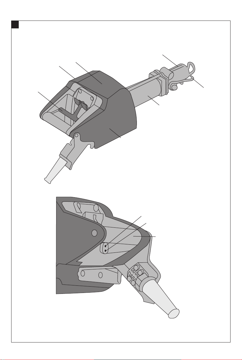
Operating controls and parts of the tool
햲 ON / OFF switch
햳 Fault indicator (red LED)
햴 Ready and service indicator (green LED)
햵 Chuck
햶 Drill bit lock
햷 Rotary hammer drill
햸 Hammering mechanism
햹 Electronics
햺 Gearing section
햻 Grip
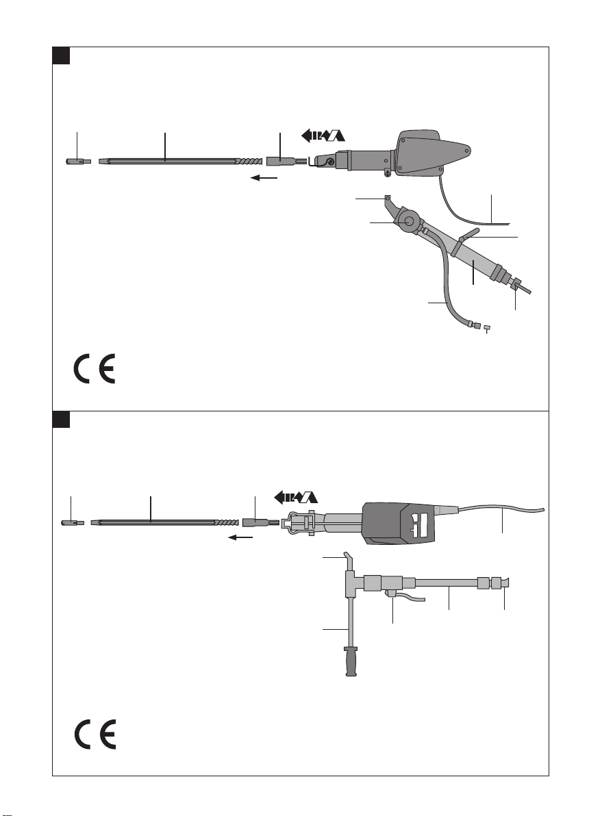
Tool with water leg
햽 Connecting cable
햾 Water leg
햿 Connecting pin
헀 Water hose
헁 Water hose protective sleeve
헂 Regulating valve
헃 Support base
헄 Carrying handle
헅 Connection end
헆 Drill bit
쎻
21
Drill steel
Tool with side handle
햽 Connecting cable
햿 Connecting pin
헀 Water hose
헁 Water hose connection sleeve
헅 Connection end
헆 Drill head
쎻
21
Drill rod
쎻
22
Side handle
쎻
23
Ball valve
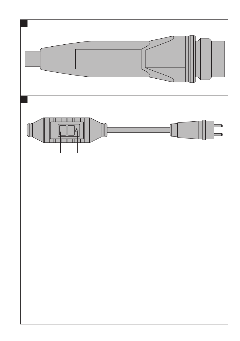
Plug and PRCD (no explosion protection!)
Tool versions: TE MD20 LS T PRCD /
TE MD20 LS T HA PRCD / TE MD20 LS T EM PRCD
24
Plug
쎻
쎻
25
PRCD ground fault circuit interrupter
쎻
26
TEST button
쎻
27
RESET button
쎻
28
Indicator lamp
Contents Page
1. Generalinformation 15
2. Description 16
3. Insert toolsand accessories 16
4. Technical data 17
5. Safety rules 18
6. Before use 21
7. Operation 23
8. Care and maintenance 24
9. Troubleshooting 24
10. Disposal 26
11. Manufacturer's warranty – tools 26
12. Declaration of conformity (original) 27
1. General information
1.1 Indication of danger
-WARNING-
Draws attentionto a potentially dangeroussituation that
could lead to serious personal injury or fatality.
-CAUTION-
This wordis used to draw attentionto a potentiallydangerous situationwhich could lead tominor personal injury
or damage to the equipment or other property.
-NOTE-
Draws attention to an instruction or other useful information.
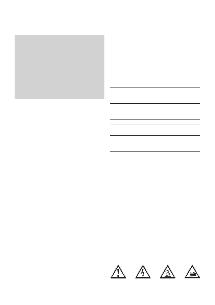
1.2 Pictograms
Warning signs
Plug with approvalfor use in environments wherethere
is a risk of explosion as per 5.8.1
Tool versions: TE MD20 LS T EM / TE MD20 LS T /
TE MD20 LS T HA / TE MD20 LS T IM
Printed: 20.04.2017 | Doc-Nr: PUB / 5136141 / 000 / 00Printed: 20.04.2017 | Doc-Nr: PUB / 5136141 / 000 / 01
General
warning
Warning:
electricity
Warning:
hot surface
Warning:
avoid hand
injuries
15
Page 6
Obligation signs
Wear eye
rotection
p
Wear a
afety
s
helmet
Wear ear
rotection
p
Wear ear
rotection
p
Wear safety
ootwear
f
Symbols
ead the
R
operating
instructions
efore use
b
These numbers refer to the corresponding illustrations. The illustrations can be foundonthefold-out cover pages. Keep thesepages open whilestudying theoperating instructions.
In these operating instructions, the designation "the tool"
alwaysrefers to the TEMD20LS T rotary hammer drill.
If the tool is used in areas where there is risk of explosion, the information printed on a grey background in
these operating instructions must be observed. No
changesormodifications maybemade to thetool without consentfromthe approval authority.
Location of identification data on the tool
The type designation andserialnumbercanbefound on
thetype plate onthe tool. Make a noteofthis data in your
operating instructionsand always refer to it when making an enquiry to your Hilti representative or service
department.
Type:
Serial no.:
2. Description
The tool is a water-cooled, electrically-powered rotary
hammer drill with pneumatic hammering mechanism.
Handheld use is only allowed with the following tools in
combination withthe sidehandleTE-MAG. Theletter„T“
in the nameofthe tools indicates thatthetool is equiped
with a „dead-man switch“.
The tool is available in various versions:
TE MD20 LS T (FFE: 2004397)
TE MD20 LS T HA (FFE: 2008150)
TE MD20 LS T IM (FFE: 2008151)
TE MD20 LS T PRCD (FFE: 2008152)
TE MD20 LS T HA PRCD (FFE: 2008153)
TE MD20 LS T EM (FFE: 2051680)
TE MD20 LS T EM PRCD (FFE: 2008154)
The TE MD20 LS T / TE MD20 LS T HA /
TE MD20 LS T EM /TE MD20 LS T IM are suitable for
use in areas where there is a risk ofexplosion and in
miningenvironments.
3. Insert tools and accessories
TE-MCEconnection end
TE-MDRdrill steel, in various lengths
TE-MDHdrill bit head, in various versions
TE-MEC extension cordfor use in areaswhere thereis a
risk of explosion.
TE-MAC PRCD adapter cable for useonly in areas where
no explosion protection is necessary; only applicable in
electric circuits wherethe nominal voltage is 220-230 V.
For rig-guided drilling:
TE-MW waterleginvariouslengthsused in conjunction
with the TE MW 2G or TE MW 4G support base (and,
where necessary, with TE MW E water leg extension in
various lengths).
For handheld drilling:
Side handleTE-MAG
Pleas contact Hilti Customer Service for more information about accessories.
16
Printed: 20.04.2017 | Doc-Nr: PUB / 5136141 / 000 / 00Printed: 20.04.2017 | Doc-Nr: PUB / 5136141 / 000 / 01
Page 7

4. Technical data
TE MD20 LS T TE MD20 LS T PRCD
TE MD20 LS T HA TE MD20 LS T HA PRCD
TE MD20 LS T EM TE MD20 LS T EM PRCD
TE MD20 LS T IM
Rated voltage 220–240 V single phase 220–230 V single phase
Rated current 15 A 15 A
Mains frequency 50–60 Hz 50–60 Hz
Torque 100 Nm 100 Nm
Revolutions (counter-clockwise) 205 r.p.m. 205 r.p.m.
Impactenergy 28 J 28 J
Dimensions 770×210×230 770×210×230
Drill bit head diameter 28–51 mm 28–51 mm
Drill steellength up to 2,4 m up to 2,4 m
Protection class I Protection class I Protection class I
Storage temperature without coolingwater –20°C to +55°C –20°C to +55°C
Noise and vibration information
(measured in accordance with EN 60745-2-6) under load
Typical A-weighted soundpower level: 109 dB (A) 109 dB (A)
Typical A-weighted emission sound pressure level: 98 dB (A) 98 dB (A)
Wear ear protection!
For the given noise level in accordance with EN 60745-2-6,
measurement uncertainty is3 dB.
a
Typical weighted vibration TE MD20 in concrete
h, HD
: 11 m/s
Uncertainty (K) 2 m/s² 2 m/s²
Weight according to EPTA-Procedure 01/2003 27,7 kg 27,7 kg
Protection against entry of water or foreign objects Plug: IP 66, IP 67 Plug: IP 44
Explosion protection I M2 / II2 G 94/9/EG No explosion
Right oftechnical changes reserved.
-NOTE-
The vibration emission level given in this information sheet has been measured in accordance with a standardised
test given in EN 60745 and may be used to compare one tool withanother.It may be used for a preliminaryassessmentof exposure.The declared vibrationemissionlevel represents the main applications of the tool. However if the
tool is used for different applications, with different accessories or poorly maintained, the vibration emission may
differ. This may significantly increase the exposure level over the total working period. An estimation of the level of
exposure to vibration should also takeinto account the timeswhenthe tool is switched off or when it is running but
not actually doing the job. This may significantly reduce the exposure level over the total working period. Identify
additional safety measures to protect the operator from the effects of vibration such as: maintain the tool and the
accessories, keep the hands warm, organisation of work patterns.
2
11 m/s
2
Tool: IP 66 PRCD: IP 55
Tool: IP 66
EEx d I/IIA T4 protection
Printed: 20.04.2017 | Doc-Nr: PUB / 5136141 / 000 / 00Printed: 20.04.2017 | Doc-Nr: PUB / 5136141 / 000 / 01
17
Page 8

5. Safety rules
In addition tothesafetyrules listed in the individual sections of these operating instructions, thefollowing points
must be strictly observed at all times.
-WARNINGRead all safety warnings and instructions.
Failure to follow the warnings andinstructionsmay result
in electric shock, fire and/or serious injury.
Save allwarnings andinstructions for future reference.
The term “power tool” in the warnings refers to your
mains-operated(corded) power tool or battery-operated (cordless) power tool.
5.1 Work area safety
a) Keep work area clean and well lit. Cluttered or dark
areas invite accidents.
b) Do not operatepowertoolsin explosive atmospheres,
such as in the presence of flammable liquids, gases ordust. Power tools create sparkswhich mayignite
the dust or fumes.
c) Keep childrenand bystanders away while operating
a power tool.Distractions cancause you to losecon-
trol.
5.2 Electrical safety
a) Power toolplugs mustmatch the outlet. Never mod-
ifythe plug inany way. Do notuse anyadapterplugs
with earthed (grounded) power tools. Unmodified
plugsandmatching outlets will reduce risk of electric
shock.
b) Avoid body contact with earthed or grounded sur-
faces, such as pipes, radiators, ranges and refrigerators.There is an increased risk of electric shock if
your body is earthed or grounded.
c) Do notexposepower toolstorain orwet conditions.
Water entering a power tool will increase the risk of
electric shock.
d) Do not abuse the cord. Never use the cord for car-
rying, pulling or unplugging the power tool. Keep
cord away from heat, oil, sharp edges or moving
parts. Damagedor entangled cordsincrease the risk
of electric shock.
e) When operating apower tool outdoors,use an exten-
sion cord suitable for outdoor use. Use ofacord suit-
able for outdoor usereduces therisk ofelectricshock.
f) Use of the power tool is permissible only in con-
junction withanAC/DCsensitivegroundfault circuit
breaker with aratingofmax. 10 mA (typeA or B, as
per IEC 61008) or an equivalentor better protective
system(insulationorearth/ground leakage sensor).
Use of a protective system of this kind reduces the
risk of electric shock.
5.3 Personal safety
a) Stay alert, watch what you are doing and use com-
monsense when operatinga power tool. Do notuse
a power tool while you are tired or under the influence of drugs, alcohol or medication. A moment of
inattention whileoperating powertools may result in
serious personal injury.
b) Use personal protective equipment. Always wear
eye protection. Protective equipment such as dust
mask, non-skidsafety shoes, hard hat, or hearing protection used for appropriate conditions will reduce
personal injuries.
c) Prevent unintentional starting. Ensure the switch is
d) Remove any adjusting key or wrench before turning
e) Do not overreach. Keep proper footing and balance
f) Dress properly. Do not wear loose clothing or jew-
g) If devices are provided for the connection of dust
5.4 Power tool use and care
a) Do not force the power tool. Use the correct power
b) Do not use the power tool if the switch does not turn
c) Disconnect the plug from the power source and/or
d) Store idle power tools out of the reach of children
inthe off
and/or battery pack, picking up or carrying the tool.
Carrying power tools with your finger on the switch
or energising power tools that have the switch on
invites accidents.
the power tool on. A wrench or a key left attached to
a rotating part of the power tool may result in personal
injury.
at all times. This enables better control of the power
tool in unexpected situations.
ellery. Keep your hair, clothing and gloves away
from moving parts. Loose clothes, jewellery or long
hair can be caught in moving parts.
extraction and collection facilities, ensure these are
connected and properly used. Use of dust collection
can reduce dust-related hazards.
tool for your application. The correct power tool will
do the job better and safer at the rate for which it was
designed.
it on and off. Any power tool that cannot be controlled
with the switch is dangerous and must be repaired.
the battery pack from the power tool before making
any adjustments, changing accessories, or storing
power tools. Such preventive safety measures reduce
the risk of starting the power tool accidentally.
and do not allow persons unfamiliar with the power tool or these instructions to operate the power
tool. Power tools are dangerous in the hands of
untrained users.
position before connecting to power source
18
Printed: 20.04.2017 | Doc-Nr: PUB / 5136141 / 000 / 00Printed: 20.04.2017 | Doc-Nr: PUB / 5136141 / 000 / 01
Page 9

e) Maintain power tools. Check for misalignment or
binding of moving parts, breakage of parts and any
other condition that may affect the power tool’s operation. If damaged, have the power tool repaired
before use. Many accidents are caused by poorly
maintained power tools.
f) Keep cutting tools sharp and clean. Properly main-
tained cutting tools with sharp cutting edges are less
likely to bind and are easier to control.
g) Use the power tool, accessories and tool bits etc.
in accordance with these instructions, taking into
account the working conditions and the work to be
performed. Use of the power tool for operations dif-
ferent from those intended could result in a hazardous
situation.
5.7 Safety rules for rotary hammers and breakers
● TWear ear protectors. Exposure to noise can cause
hearing loss.
● Use the side handle supplied with the tool. Loss of
control can cause personal injury.
● Hold power tool by insulated gripping surfaces when
performing an operation where the accessory may
contact hidden wiring or the power tool's own cord.
Contact with a “live” wire may make exposed metal
parts of the power tool “live” and could give the operator an electric shock.
5.8.1 Correct use
5.5 Service
a) Have your power tool serviced by a qualified repair
person using only identical replacement parts. This
will ensure that the safety of the power tool is maintained.
5.6 General safety rules for supporting or securing
devices
WARNING Read all safety rules and instructions supplied with the supporting / securing device or power
tool. Failure to follow the warnings and instructions may
result in electric shock, fire and/or serious injury.
Save all warnings and instructions for future reference.
The term “power tool” in the warnings refers to your
mains-operated (corded) power tool or battery-operated (cordless) power tool.
● Disconnect the plug from the power source and/or
the battery pack from the power tool before making
any adjustments, changing accessories, or storing
power tools. Power tools starting inadvertently are
the cause of many accidents.
● Set up the supporting or securing device properly
before fitting the power tool. Correct assembly is
important in order to avoid risk of collapse.
● Mount the power tool securely on the supporting /
securing device before use. Movement of the power
tool on the supporting / securing device may lead to
a loss of control.
● Set up the supporting / securing device on a solid,
even and level surface. The power tool cannot be
guided smoothly and safely if the supporting / securing device is unsteady or moves out of place.
● Do not overload the supporting / securing device and
do not use it as a substitute for a ladder or working
platform. Overloading or standing on the supporting
/ securing device may raise its point of balance and
cause it to topple over.
a) Environmental conditions
Amendment to 5.1.b
TE MD20 LS T / TE MD20 LS T HA / TE MD20 LS T IM
Use of the TE MD20 LS T / TE MD20 LS T HA /
TE MD20 LS T IM / TE MD20 LS T EM tools in areas
where there is a risk of explosion is permissible.
These tools comply with the requirements of 94/9/EC
(ATEX) for
Group I cat. M2 → Mining and in atmospheres where
there is a risk of explosion
Group II cat. 2G → Other areas where there is a risk of
explosion, where gasses and vapors of the Group IIA
(at the request of the customer also gasses and vapors
of the Group IIB) with ignition temperatures above 135°C
may occur.
TE MD20 LS T PRCD / TE MD20 LS T HA PRCD /
TE MD20 LS T EM PRCD
Do not work with these tools in areas where there is a
risk of explosion in which flammable liquids gases or
dusts are present.
Electric tools generate sparks which could ignite the dust
or vapors.
Amendment to 5.2.c
The tool must only be used under environmental conditions where the single parts (tool, plugs, if applicable PRCD) are adequately protected against ingress of
water or other foreign matter according to their rated
IP-protection class.
Printed: 20.04.2017 | Doc-Nr: PUB / 5136141 / 000 / 00Printed: 20.04.2017 | Doc-Nr: PUB / 5136141 / 000 / 01
19
Page 10

Amendment to 5.2.e
Use only extension cords which are approved to be
used under the existing environmental conditions.
b) The tool is designed for drilling in rock (not in rein-
forced concrete) with drill bits of 28–51 mm diameter to depths of up to 2.4 m.
c) Use the power tool correctly for its intended applica-
tion and only when it is in good condition.
d) Tampering with or modification of the power tool, its
switch or grips is not permissible.
e) The tool and its ancillary equipment may present haz-
ards when used incorrectly by untrained personnel or
not as directed.
f) To avoid the risk of injury, use only genuine Hilti acces-
sories and ancillary equipment.
g) Observe the information printed in the operating instruc-
tions concerning operation, care and maintenance.
5.8.2 General hazards presented by the tool
● Keep the grips dry, clean and free from oil and grease.
● Do not touch or hold rotating parts.
● Never leave the tool unsupervised.
● When not in use, the tool must be stored in a dry place,
locked up or where out of reach of unauthorised persons
and children.
● Ensure that the workplace is well ventilated.
● Objects which could cause injury should be removed
from the working area.
● Keep other persons in particular children outside the
area affected while you are working.
● To avoid tripping while working, always lead the sup-
ply cord, extension cord and water hose away to the
rear of the tool.
ATTENTION!
● Use only the original accessories or items of additional
equipment listed in the operating instructions. The use
of other drill heads or accessories may present a risk
of injury.
Mechanical hazards
Electrical hazards
● Ensure that the tool is earthed and that the earth con-
nection has been checked for correct functionality.
Operation of the tool without an earth connection presents a risk of fatal accident.
-WARNING-
● Use the tool only when connected to an electric sup-
ply equipped with a pulse-controlled ground fault circuit interrupter (type A or B as per IEC 61008) or a corresponding PRCD with a max. sensitivity rating of 10
mA. Check to ensure that the ground wire circuit is not
broken when the ground fault circuit interrupter or
PRCD is triggered. Equivalent or superior protective
systems may be used (e.g. ground leakage sensor for
the AC/DC circuit).
● Check the condition of the electric supply and exten-
sion cords and plug connectors at regular intervals.
Replace damaged extension cords.
● To avoid safety hazards repairs to Hilti power tools and
their electric supply cords and plugs must be carried
out only by a trained repair specialist certified by Hilti.
● To avoid safety hazards repairs to Hilti extension cords
and their plugs and and couplers electric supply cords
and plugs must be carried out only by a trained repair
specialist certified by Hilti.
● Do not touch the supply cord in the event of it becom-
ing damaged while working. Disconnect the supply
cord plug from the socket.
● Do not use the supply cord or extenison cord for pur-
poses for which they were not intended.
● Never carry the tool by the supply cord.
● Check that the ON / OFF switch works correctly each
time before using the power tool. The power tool must
switch off automatically when the switch is released.
Have switches repaired by a suitably trained repair specialist authorized by Hilti.
Thermal hazards
● Follow the instructions concerning care and mainte-
nance and change drill bits in good time.
-NOTE-
The following information printed on the grey background
has to be generally respected for all tools and in all environsments.
The drill steel connection end and chuck are coordinated components that form an integral part of the explosion protection system. Ensure that genuine Hilti insert
tools are used and that they are correctly fitted and
secured in the chuck.
20
Printed: 20.04.2017 | Doc-Nr: PUB / 5136141 / 000 / 00Printed: 20.04.2017 | Doc-Nr: PUB / 5136141 / 000 / 01
● Operate the tool only when water is flowing in order
to prevent overheating of the power tool, the drill head
and the drill steel.
5.8.3 Requirements to be met by users
● The tool is intended for professional use.
-NOTE-
The following information printed on the grey background
has to be generally respected for all tools and in all environsments.
Page 11

The tool may be operated, serviced and repaired only
by authorised, trained personnel. This personnel must
be informed of any special hazards that may be encountered.
5.8.4 Personal protective equipment
The user and persons in the immediate vicinity must wear
suitable eye protection, a safety helmet, ear protection, protective gloves and safety footwear when the tool is in use.
6. Before use
It is essential that safety rules printed in these operating
instructions are read and observed.
-CAUTION-
The tool must be disconnected from the mains supply
while being set up and made ready for use.
6.1 Fitting the drill bit
Parts used: TE-MDR and TE-MDH
Push the drill bit head onto the front end of the drill steel
and tap it lightly until it holds securely.
-CAUTION-
■ The tool, drill bit and drill support are
heavy.
■ There is a risk of pinching parts of the
body.
■ Wear a safety helmet, protective gloves
and safety footwear.
-CAUTION-
■ The drill bit may become hot during use.
■ There is a risk of burning the hands.
■ Wear protective gloves when changing
drill bits.
6.2 Fitting the drill steel
Use TE-MDR drill steels or drill steels according Hilti
specification with appropriate fit to the tool only.
(Comment: Hilti rods differ in length and shape of the
connecting part to standard rods)
1. Clean away any dirt adhering to the connection end
and apply a little grease to it.
2. Screw the drill steel fully into the connection end.
3. Guide the connection end into the chuck and rotate it
until the grooves and splines are in alignment and then
push it in as far as it will go.
4. Close the chuck locking mechanism and check that
the connection end is held securely.
6.3 Fitting the water leg/side handle
Use only the TE-MW water leg (with fitted TE-MW 2G or
TE-MW 4G support base) intended for use with the power
tool, or the TE-MAG side handle as water supply is assured only when these parts are used.
1. Clean off any dirt adhering to the connecting pin on
the water leg / side handle.
2. Position the guide on the underside of the front housing of the tool on the water leg / side handle and insert
the connecting pin in the hole provided.
3. Secure the connection by inserting the retaining pin
in the hole in the connecting pin.
4. The securing plate on the connecting pin must be
released before separating the tool from the water leg
/ side handle (e.g. for transport). The water leg / side
handle can then be pulled away fromthe tool.
6.4 Water connection
-NOTE-
The following information printed on the grey background
has to be generally respected for all tools and in all environsments.
The tool and drill bit are water-cooled and the water has
a flushing function during drilling.
– Water pressure: min. 3 bar, max. 5 bar
– Water temperature: approx. 10–20°C
– Cooling water flow rate: approx. 10 l/min
– Permissible degree of water pollution: <40 µm.
-NOTE-
In order to ensure that the maximum permitted water
pressure of 5 bar at the power tool is not exceeded, a
pressure reduction valve is incorporated in the the TEMW water leg and in the TE-MAG side handle. The maximum water pressure in the supply line to the pressure
reduction valve in the water leg or side handle must not
exceed p
max
= 20 bar.
The cooling water is supplied to the tool through a stud
on the water leg saddle/ side handle which is connected
to the water supply.
If the Hilti TE-MW water legs or TE-MAG side handles
are used, connection to them is by way of a 1" tapered
sleeve.
Check the flow of water. Water must spray out of the
bores in the drill bit.
6.5 Electrical connection
6.5.1 General points
The tool must be powered by an alternating current sup-
Printed: 20.04.2017 | Doc-Nr: PUB / 5136141 / 000 / 00Printed: 20.04.2017 | Doc-Nr: PUB / 5136141 / 000 / 01
21
Page 12

ply that complies with the information given on the type
plate.
The tool must be connected to an adequately dimensioned earth conductor by way of the mains plug. The
earth connection must be checked at regular intervals to
ensure correct functionality.
The electric supply must be equipped with a pulse-controlled / DC-sensitive ground fault circuit breaker (type
A or B as per IEC 61008) with a sensitivity of max. 10
mA. This device must be checked at regular intervals in
accordance with the manufacturer’s instructions.
Equivalent or superior protective systems may be used
(e.g. ground leakage sensor for the AC/DC circuit).
6.5.2 Connecting the TE MD20 LS T /
TE MD20 LS T HA / TE MD20 LS T EM /
TE MD20 LS T IM to the electric supply
If operated in atmospheres where there is a risk of
explosion
Only approved plug/socket systems (EEx d I/IIA, IP66)
in accordance with 94/9/ EC may be used, e.g. Hilti
TE-MPH with intrinsically safe pilot contact, monitored
earth/ground, 220–240 V phase, neutral conductor. Disconnection from the power supply must be by way of
an isolating switch.
-CAUTION-
Check to ensure that the tool is switched off before connecting it to the electric supply.
-NOTE-
The plug is equipped with a pilot contact which allows
use of an external ground connection monitoring system
(pilot contact switching). In addition, in the TE MD20 LS
T, TE MD20 LS T EM and TE MD20 LS T HA, a diode is
fitted between the pilot contact and the ground lead. A
line terminator is incorporated in the TE MD20 LS T IM.
The monitoring circuit must be self-testing (intrinsically safe) in accordance with EN/IEC 60079-11.
6.5.3 Connecting the TE MD20 LS T PRCD /
TE MD20 LS T HA PRCD / TE MD20 LS T EM
PRCD to the electric supply
Ground fault circuit interrupters of the PRCD type are
incorporated in the supply cords of the TE MD20 LS T
PRCD / TE MD20 LS T HA PRCD / TEMD20 LS T EM
PRCD. When making one of these tools ready for use,
proceed as follows:
-CAUTION-
Check to ensure that the tool is switched off before connecting it to the electric supply.
1. Plug the tool's supply cord into the electric supply
socket.
2. Press the "RESET" button on the PRCD ground fault
circuit interrupter (the indicator lamp must then light).
3. Press the "TEST" button on the PRCD ground fault
circuit interrupter (the indicator lamp must then go
out).
-WARNING-
If the indicator lamp continues to light, further use of the
tool is not permissible. Have the tool repaired by a qualified specialist using genuine spare parts.
4. Press the "RESET" button on the PRCD ground fault
interrupter (the indicator must then light).
The tool is then ready for operation.
6.6 Use of extension cords and connecting cables
Use only extension cords and adapter cords of adequate
cross section which have been approved for use in the
application concerned. The cord may otherwise overheat
or a drop in performance may occur.
The recommended conductor cross-section is 2.5 mm
over a length of max. 60 m.
Check that the extension cord and plug are adequately
protected by a suitably-rated fuse in the electric supply.
To avoid overheating, always unroll the full length of the
extension cord from the drum even when only a short
length is required.
Connect the tool to the electric supply only once it has
been set up ready for use.
-NOTE-
When the tool is operated in areas where there is a risk
of explosion, only approved extension cords or supply
cords may be used, the plugs or connectors (TE-MPH)
of which must be approved for use in damp areas and
designed to ensure safe connection and disconnection
in areas where there is a risk of explosion (please also
refer to section 6.5).
-NOTE-
When the tool is operated in areas where there is no risk
of explosion, extension cords which are at least approved
for use in damp areas / outdoors must be used. The plug
on the tool's supply cord and the connector on the extension cord must be fully compatible and ensure the specified degree of protection against ingress of water or other foreign matter.
6.7 Use of a generator or transformer
When the tool is powered by a generator or transformer,
the following conditions must be fulfilled:
● AC voltage, output power at least 7000 VA.
● The operating voltage must be within +5% and –10%
of the rated voltage at all times.
● Frequency range 50–60 Hz.
● Automatic voltage regulation with starting boost.
● The unit must be correctly earthed.
● A ground fault circuit breaker as described at section
6.5 must be used. Equivalent or superior protective
systems may be used (e.g. ground leakage sensor for
the AC/DC circuit).
Never operate other machines or appliances from the
generator or transformer at the same time. Switching
other machines or appliances on and off may cause
undervoltage and / or overvoltage peaks, resulting in
damage to the tool.
2
22
Printed: 20.04.2017 | Doc-Nr: PUB / 5136141 / 000 / 00Printed: 20.04.2017 | Doc-Nr: PUB / 5136141 / 000 / 01
Page 13

7. Operation
It is essential that the safety precautions printed in these
operating instructions are read and observed.
-CAUTION-
■ The tool and the drilling operation emit
noise.
■ Excessive noise may damage the hearing.
■ Wear ear protection
-CAUTION-
■ Drilling may cause hazardous splintering of the material.
■ Splintering material may injure parts of
the body and the eyes.
■ Wear eye protection and a safety helmet.
-CAUTION-
Take care to ensure that you are in a secure, stable position before switching the tool on. Check that you are able
to operate the ON / OFF switch with the hand on the rear
grip reliably at all times.
7.1 Drilling
-NOTE-
The following information printed on the grey background
has to be generally respected for all tools and in all environsments.
1. Open the water valve on the water leg. Make sure that
water flows continuously while drilling.
2. Bring the tool with the water leg into the drilling position.
3. Switch on at the ON / OFF switch.
4. Regulate the contact pressure at the water leg so that
the drill bit runs centrally in the hole being drilled. The
tool should hammer evenly without kicking back.
5. Move the water leg as necessary, as the drilling operation continues.
-NOTE-
● In the event of the drill bit head jamming in the hole
while drilling, proceed as follows:
● Leave the power tool switched on and hold it secure-
ly as the forces that occur may be higher than during
normal operation (this is due to activation of the slip
clutch - the mechanical device that disconnects the
motor from the gearing).
● Free the jammed drill bit by altering the drilling advance
pressure through adjustment of the control valve on
the water leg.
● If this fails to free the jammed drill bit, switch off the
power tool, separate the power tool from the drill steel
and then use a suitable tool to extract the drill bit from
the hole.
-CAUTION-
When retracting the water leg, take care to ensure that
no parts of the body are pinched between the moving
part and the fixed part of the water leg.This presents a
risk of injury!
7.1.2 Drilling with the side handle
-NOTE-
From ergonomic point of view handheld drilling with the
side handle can only be recommended vertical down. For
applications sideways or upwards the tool may be used
with the water leg.
1. Open the ball valve on the side handle. Make sure that
water flows continuously while drilling.
2. Bring the tool into the drilling position.
3. Switch on at the ON / OFF switch.
4. Guide the tool in a way that the drill bit runs centrally
in the hole being drilled.
5. Press the tool against the underground that the tool
hammers evenly without kicking back.
-NOTE-
To handle the tool safely the maximum length of the drill
rod has to be adapted to the existing working conditions
(drilling angle, size of user, etc.). Drill deep holes where
required with drill rods with increasing lengths or work
on suitable platforms with changeable heights.
-NOTE-
In the event of the drill head jamming in the hole while
drilling, proceed as follows:
● Leave the power tool switched on and hold it secure-
ly as the forces that occur may be higher than during
normal operation (this is due to activation of the slip
clutch - the mechanical device that disconnects the
motor from the gearing).
● Free the jammed drill bit by altering the drilling advance
pressure through adjustment of the control valve on
the water leg.
● If this fails to free the jammed drill bit, switch off the
power tool, separate the power tool from the drill steel
and then use a suitable tool to extract the drill bit from
the hole.
7.2 Finishing drilling
1. Pull the drill steel and drill head out of the hole while
the tool is still running.
2. Switch off at the ON / OFF switch.
3. Close the water valve on the water leg / side handle.
Removing the drill bit: Lay the drill steel down flat on a
hard surface so that the full length of the drill bit is in contact with this surface. Strike the side of the drill bit with
a hammer several times while rotating the drill steel
between each hammer blow. The hammer blows should
cause the drill bit to be released from the drill steel. Take
care to avoid damage to the drill steel.
Printed: 20.04.2017 | Doc-Nr: PUB / 5136141 / 000 / 00Printed: 20.04.2017 | Doc-Nr: PUB / 5136141 / 000 / 01
23
Page 14

-CAUTION-
Take care to ensure that no persons in the vicinity are
injured when removing the drill bit.
8. Care and maintenance
Disconnect the supply cord plug from the mains socket.
8.1 Care of insert tools
Remove any dirt adhering to the surface of the insert
tools and protect them from corrosion by rubbing them
with an oily cloth from time to time.
8.2 Care of the tool
The outer casing of the tool is manufactured from impactresistant plastic. The grip section is manufactured from
synthetic rubber.
-NOTE-
The following information printed on the grey background
has to be generally respected for all tools and in all environsments.
Check all external parts of the tool for damage at regular intervals and check that all controls operate faultlessly. Damaged plastic parts of the housing must be
replaced immediately due to their explosion protection
function.
Use a slightly damp cloth to clean the outside of the tool
at regular intervals. Always keep the grip sections of the
tool free from oil and grease. Do not use cleaning agents
or polishes, etc., containing silicone.
Keep the chuck clean. Check the drill steel for damage
and wear at the grooves and ensure that the water passage is not obstructed.
Do not operate the tool when parts are damaged or when
the controls do not operate faultlessly. If necessary, have
the tool repaired at a Hilti service centre.
Electrical sections of the tool may be repaired only by
trained electrical specialists.
8.3 Maintenance of the tool
Regular maintenance is necessary in order to ensure that
the tool remains ready for use when required. After a preset number of operating hours, the operating status lamp
(green lamp) begins to blink. The tool may continue to
be operated for some time in this state. The tool will finally switch itself off after the set service interval is exceeded by more than 10%.
The tool must be serviced at an authorized Hilti service
center.
Repairs to the power tool and plug connector system
are subject to restrictions concerning electrical safety
and approval / explosion protection requirements and
may thus be carried out only by suitably trained specialists authorized by Hilti.
8.4 Checking the tool after care and maintenance
After care and maintenance work, the specified checks
and inspections must be carried out and documented
accordingly.
9. Troubleshooting
9.1 Explanation of the operating status / service indicator lamps
The tool is equipped with two lamps which indicate its operating status or faults by lighting in different ways:
Fault indicator Ready and Tool status Cause / action required
(red lamp) service indicator
Off Off The tool is not ready. No electric power.
Off Lights The tool is ready for operation.
Lights Lights The tool has overheated. The tool has switched itself off.
Blinks Lights Fault in the tool or electric supply The tool has switched itself off.
Off Blinks Servicing is due. Have the tool serviced at a Hilti
24
Printed: 20.04.2017 | Doc-Nr: PUB / 5136141 / 000 / 00Printed: 20.04.2017 | Doc-Nr: PUB / 5136141 / 000 / 01
(green lamp)
See “Troubleshooting”
The red lamp remains lit until the
tool has cooled down.
The tool does not restart automatically after cooling down (switch
must be operated).
voltage. See “Troubleshooting”
service center.
Page 15

9.2 Troubeshooting
Fault Possible cause Remedy
The tool doesn’t start and the green No voltage from the electric supply. Plug in a different power tool of the
ready indicator doesn’t light. type (TE MD20) and check whether
it works. If the fault persists: Check
the electric supply (fuses, circuit
interrupters or equivalent protective systems or pilot contact circuit). If necessary, have the power
tool repaired by a qualified electrical specialist.
Fault or poor contact in the extension Replace the extension cord and
cord or plug connectors. check whether the tool works.
Return defective parts to Hilti
Service.
The tool doesn’t start and the fault The tool has overheated. Check the water supply. Allow the
indicator (red lamp) lights. tool to cool down. The tool is ready
for further use when the red lamp
no longer lights.
The tool doesn’t start and the fault The tool is faulty or an internal Switch the tool off and then on
indicator (red lamp) blinks. safety function has been activated. again (reset). If the fault persists:
Switch the power tool off and disconnect it from the electric supply.
Reconnect it to the electric supply
after approx. 20 sec. and switch
back on at the ON / OFF switch.
If the fault persists, have the pow-
er tool repaired by a qualified
electrical specialist.
If the fault persists, have the power tool checked by Hilti Service.
The connection end is broken off in 1. Disconnect the tool from the
the chuck. electric supply.
2. Open the locking mechanism.
3. Remove the broken piece of the
connection end.
No water flows. Check the water supply to the
water leg / side handle.
Check that the connecting pin and
drill steel are seated correctly.
Check that water can flow through
the drill bit head.
Printed: 20.04.2017 | Doc-Nr: PUB / 5136141 / 000 / 00Printed: 20.04.2017 | Doc-Nr: PUB / 5136141 / 000 / 01
25
Page 16

10. Disposal
Return waste material for recycling
Most of the materials from which Hilti power tools are manufactured can be recycled. The materials must be correctly separated before they can be recycled. In many countries, Hilti has already made arrangements for taking back
your old electric tools for recycling. Please ask your Hilti customer service department or Hilti sales representative
for further information.
Disposal of drilling slurry
With regard to environmental aspects, allowing drilling slurry to flow directly into rivers, lakes or the sewerage system without suitable pre-treatment is problematical. Ask the local authorities for information about applicable regulations.
We recommend the following pre-treatment:
● Collect the drilling slurry (e.g. use an industrial vacuum cleaner).
● Allow the slurry to settle and dispose of the solid material at a construction waste disposal site (the addition of a
flocculent may accelerate the settling process).
● Water from the drilling slurry should be neutralised by adding a neutralising agent or large quantity of water before
it is allowed to flow into the sewerage system.
Only for EU countries
Disposal of electric tools together with household waste is not permissible!
In observance of European Directive on waste electrical and electronic equipment and its implemen-
tation in accordance with national law, electric tools that have reached the end of their life must be collected separately and returned to an environmentally compatible recycling facility.
11. Manufacturer's warranty – tools
Hilti warrants that the tool supplied is free of defects
in material and workmanship. This warranty is valid so
long as the tool is operated and handled correctly,
cleaned and serviced properly and in accordance with
the Hilti Operating Instructions, and the technical system is maintained. This means that only original Hilti
consumables, components and spare parts may be
used in the tool.
This warranty provides the free-of-charge repair or
replacement of defective parts only over the entire lifespan of the tool. Parts requiring repair or replacement
as a result of normal wear and tear are not covered by
this warranty.
Additional claims are excluded, unless stringent
national rules prohibit such exclusion. In particular,
Hilti is not obligated for direct, indirect, incidental
or consequential damages, losses or expenses in
connection with, or by reason of, the use of, or inability to use the tool for any purpose. Implied warranties
of merchantability or fitness for a particular purpose
are specifically excluded.
26
Printed: 20.04.2017 | Doc-Nr: PUB / 5136141 / 000 / 00Printed: 20.04.2017 | Doc-Nr: PUB / 5136141 / 000 / 01
For repair or replacement, send tool or related parts
immediately upon discovery of the defect to the address
of the local Hilti marketing organization provided.
This constitutes Hilti's entire obligation with regard to
warranty and supersedes all prior or contemporaneous comments and oral or written agreements concerning warranties.
Page 17

12. EC declaration of conformity
((original)
Designation: Rotary hammer
Type: TE MD20 LS T, TE MD20 LS T HA
Year of design: 2002
We declare, on our sole responsibility, that this product
complies with the following directives and standards:
94/9/EC, 2011/65/EU, 2006/42/EC,EN ISO 12100, EN
60079-0, EN 60079-1, EN 60745-1, EN 60745-2-6.
Certificate number: DMT 02 ATEX E 208 X
Issued by: EXAM BBG
Prüf- und Zertifizier GmbH
Dinnendahlstr. 9
D-44809 Bochum
Germany
Designation: Rotary hammer
Type: TE MD20 LS T EM, TE MD20 LS T IM
Year of design: 2002
We declare, on our sole responsibility, that this product
complies with the following directives and standards:
94/9/EC, 2011/65/EU, 2006/42/EC, 2004/108/EC, EN ISO
12100, EN 60079-0, EN 60079-1, EN 60745-1, EN 607452-6.
Certificate number: DMT 02 ATEX E 208 X
Issued by: EXAM BBG
Prüf- und Zertifizier GmbH
Dinnendahlstr. 9
D-44809 Bochum
Germany
Hilti Corporation Feldkircherstrasse 100,
FL-9494 Schaan
elmut Haas Lars Tänzer
H
Quality Manager Head of Natural Recourses
06/2012 06/2012
Technical documentation filed at:
Hilti Entwicklungsgesellschaft mbH
Zulassung Elektrowerkzeuge
Hiltistrasse 6
86916 Kaufering
Deutschland
Designation: Rotary hammer
Type: TE MD20 LS T PRCD,
TE MD20 LS T HA PRCD
Year of design: 2002
We declare, on our sole responsibility, that this product
complies with the following directives and standards:
2011/65/EU, 2006/42/EC, EN ISO 12100, EN 60745-1,
EN 60745-2-6.
Designation: Rotary hammer
Type: TE MD20 LS T EM PRCD
Year of design: 2002
We declare, on our sole responsibility, that this product
complies with the following directives and standards:
2011/65/EU, 2006/42/EC,204/108/EC, EN SO 12100, EN
EN 60745-1, EN 60745-2-6.
Printed: 20.04.2017 | Doc-Nr: PUB / 5136141 / 000 / 00Printed: 20.04.2017 | Doc-Nr: PUB / 5136141 / 000 / 01
27
Page 18

28
Printed: 20.04.2017 | Doc-Nr: PUB / 5136141 / 000 / 00Printed: 20.04.2017 | Doc-Nr: PUB / 5136141 / 000 / 01
Page 19

Hilti Corporation
LI-9494 Schaan
Tel.:+423/2342111
Fax:+423/ 2342965
www.hilti.com
Hilti = registered trademark of Hilti Corp., Schaan
W 3891 | 0113 | 00-Pos. 1 | 1
Printed in Liechtenstein © 2013
Right of technical and programme changes reserved S. E. & O
Printed: 20.04.2017 | Doc-Nr: PUB / 5136141 / 000 / 00Printed: 20.04.2017 | Doc-Nr: PUB / 5136141 / 000 / 01
*2009360*
.
2009360 / A3
2009360
 Loading...