

Page 1
TE905-A VR
*376551*
376551
Operating instructions en
Mode d’emploi fr
Manual de instrucciones es
Manual de instruções pt
Page 2
2 47
6
3
9
1
8
5
10
TE 905
1
Page 3

UL listed to US and Canadian safety standards
Homologué UL (conforme aux normes de sécurité américaines et canadiennes)
Producto homologado según normas de seguridad americanas y canadienses
Produto homologado de accordo com as normas de segurança americanas e canadianas
CUS
R
Page 4
2
3
4 5
Page 5

1
en
It is essential that the operating instructions
are read before the tool is operated for the
first time.
Always keep these operating instructions
together with the tool.
Ensure that the operating instructions
are with the tool when it is given to other
persons.
TE905-A VR breaker
1. General information
1.1 Signal words and their meaning
-CAUTION-
Used to draw attention to a potentially dangerous situation which could lead to minor personal injury or damage to the equipment or other property.
-NOTE-
Used to draw attention to an instruction or other useful
information.
1.2 Pictograms
Contents Page
1. General information 1
2. General safety rules 2
3. Specific safety rules and symbols 3
4. Functional description 3
5. Assembly 4
6. Operation 5
7. Care and maintenance 6
8. Tools and accessories 7
9. Troubleshooting 7
10. Disposal 8
11. Warranty 8
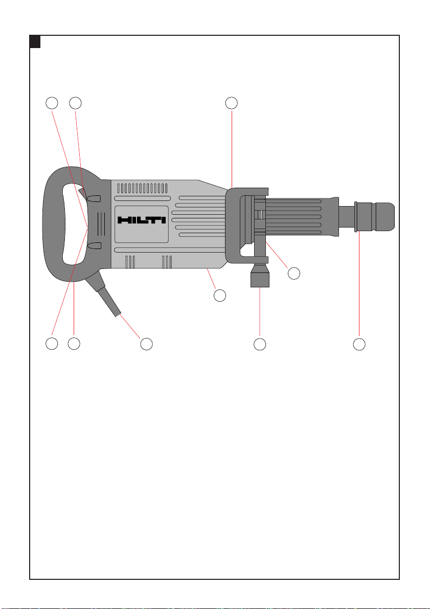
Operating controls and components
Chuck
On/off switch
Grip
Side handle
Side handle clamp
Screw
Service indicator
Activation indicator (theft protection system)
(available as option)
Supply cord
Ventilation slots
These numbers refer to the corresponding illustrations. The illustrations can be found on the fold-out cover
pages. Keep these pages open while studying the operating instructions.
In these operating instructions, the TE905-AVR breaker
is referred to as "the tool".
Location of identification data on the tool
The type designation can be found on the rating plate
and the serial number on the side of the motor housing.
Make a note of this data in your operating instructions
and always refer to it when making an enquiry to your
Hilti representative or service department.
Type: TE905-AVR
Serial no.:
Warning signs
General
warning
Warning:
electricity
Warning:
hot surface
Obligation signs
Wear
a safety
helmet
Wear
breathing
protection
Wear
ear
protection
Wear
protective
gloves
Wear
eye
protection
Read the
operating
instructions
before use.
Symbols
Equipped with
theft protection
system
Page 6

2
en
2. General safety rules
1. WARNING!
Read and understand all instructions.
Failure to follow all instructions listed below may
result in electric shock, fire and/or serious personal
injury.
SAVE THESE INSTRUCTIONS
2. Work Area
Keep your work area clean and well lit. Cluttered
benches and dark areas invite accidents.
Do not operate power tools in explosive atmospheres, such as in the presence of flammable
liquids, gases, or dust. Power tools create sparks
which may ignite the dust or fumes.
Keep bystanders, children and visitors away while
operating a power tool. Distractions can cause you
to lose control.
3. Electrical Safety
Grounded tools must be plugged into an outlet properly installed and grounded in accordance with all codes
and ordinances.Never remove the grounding prong or
modify the plug in any way.Do not use any adaptor
plugs.Check with a qualified electrician if you are in
doubt as to whether the outlet is properly grounded.If
the tools should electrically malfunction or break down,
grounding provides a low resistance path to carry electricity away from the user.
Applicable only to Class I (grounded) tools.
Avoid body contact with grounded surfaces such as
pipes, radiators, ranges and refrigerators. There is
an increased risk of electric shock if your body is
grounded.
Don’t expose power tools to rain or wet conditions.
Water entering a power tool will increase the risk of
electric shock.
Do not abuse the cord. Never use the cord to carry
the tools or pull the plug from an outlet. Keep cord
away from heat, oil, sharp edges or moving parts.
Replace damaged cords immediately. Damaged
cords increase the risk of electric shock.
When operating a power tool outside, use an outdoor extension cord marked «W-A» or «W». These
cords are rated for outdoor use and reduce the risk of
electric shock.
4. Personal Safety
Stay alert, watch what you are doing and use common sense when operating a power tool. Do not
use a tool while tired or under the influence of
drugs, alcohol, or medication. A moment of inatten-
tion while operating power tools may result in serious
personal injury.
Dress properly. Do not wear loose clothing or
jewelry. Contain long hair. Keep your hair, clothing,
and gloves away from moving parts. Loose clothes,
jewelry, or long hair can be caught in moving parts.
Avoid accidental starting. Be sure switch is off
before plugging in. Carrying tools with your finger
on the switch or plugging in tools that have the
switch on invites accidents.
Remove adjusting keys or wrenches before
turning the tool on. A wrench or a key that is left
attached to a rotating part of the tool may result in
personal injury.
Do not overreach. Keep proper footing and balance
at all times. Proper footing and balance enables bet-
ter control of the tool in unexpected situations.
Use safety equipment. Always wear eye protection.
Dust mask, non-skid safety shoes, hard hat, or hearing protection must be used for appropriate conditions.
5. Tool Use and Care
Use clamps or other practical way to secure and
support the workpiece to a stable platform. Holding
the work by hand or against your body is unstable
and may lead to loss of control.
Do not force tool. Use the correct tool for your
application. The correct tool will do the job better
and safer at the rate for which it is designed.
Do not use tool if the switch does not turn it on or
off. Any tool that cannot be controlled with the switch
is dangerous and must be repaired.
Disconnect the plug from the power source before
making any adjustments, changing accessories, or
storing the tool. Such preventive safety measures
reduce the risk of starting the tool accidentally.
Store idle tools out of reach of children and other
untrained persons. Tools are dangerous in the hands
of untrained users.
Maintain tools with care. Keep cutting tools sharp
and clean. Properly maintained tools with sharp
cutting edges are less likely to bind and are easier to
control.
Check for misalignment or binding of moving parts,
breakage of parts and any other condition that may
affect the tools operation. If damaged, have the
tool serviced before using. Many accidents are
caused by poorly maintained tools.
Use only accessories that are recommended by the
manufacturer for your model. Accessories that may
be suitable for one tool may become hazardous when
used on another tool.
Page 7

3
en
6. Service
Tool service must be performed only by qualified
repair personnel. Service or maintenance performed
by unqualified personnel could result in a risk of
injury.
When servicing a tool, use only identical replacement parts. Follow instructions in the Maintenance
section of this manual. Use of unauthorized parts or
failure to follow Maintenance Instructions may create
a risk of electric shock or injury.
3. Specific safety rules and symbols
Hold tools by insulated gripping surfaces when performing an operation where the cutting tool may contact hidden wiring or its own cord.Contact with a “live”
wire will make exposed metal parts of the tool “live” and
shock the operator.
Wear ear protectors when using the tool for extended
periods. Prolonged exposure to high intensity noise can
cause hearing loss.
Personal protective equipment
The user and any other persons in the vicinity must wear
suitable eye protection, a safety helmet, ear protection,
protective gloves and breathing protection.
Symbols used on the tool:
V volts A amperes
W watts n
0
no load speed
~ alternating current /minrevolutions per minute
Hz hertz ∅ diameter
Wear
a safety
helmet
Wear
breathing
protection
Wear
ear
protection
Wear
protective
gloves
Wear
eye
protection
4. Functional description
The TE 905-AVR is a heavy-duty breaker . It is equipped
with a TE-S chuck. The tool features an active vibration
reduction system that reduces vibration by about 50%.
The tool can be equipped with an optional theft protection function. This function operates on a radio / transponder principle. When equipped with this function, the tool
can be activated and operated only by authorized users.
Correct use
The TE 905-AVR is a hand-held electric tool for chiseling.
The tool is suitable for chiseling and demolition work on
concrete, masonry, stone or asphalt. The working environment may be on a construction site of any kind.
The tool may be operated only when supplied with a voltage in compliance with the information given on its rating plate.
Chucks:
– TE-S chucks
Switches:
– On/off switch
Grips:
– Adjustable vibration-absorbing side handle.
– Vibration-absorbing grip.
Lubrication:
– Permanent lubrication.
Indicator lamps:
– Service indicator (red).
– Theft protection system indicator (available as option)
(blinks yellow).
The following items are supplied as standard:
– Tool
– Grease dispenser (50 ml)
– Operating instructions
– Toolbox
– Cleaning cloth
See figure and the explanations of operating controls
and components on page 1.
Page 8

4
en
Technical data
Tool TE 905-AVR
Rated voltage 120 V
Rated current input 15 A
Mains frequency 50–60 Hz
Weight of tool 11.3 kg (2.5 lbs)
Dimensions (l×w×h) 680×110×240 mm (26.8×4.3×9.4 in)
Chuck TE-S
Hammering speed under load 2200 blows/min
Single impact energy 20 joules
Chiseling performance in medium-hard concrete 1300 cm3/min (79.3 in3/min)
Permanent lubrication
Adjustable side handle
Foam rubber padded grip and side handle
Electronic speed (r.p.m.) limitation
On/off switch
Vibration reduction with built in AVR-system
Service indicator
Right of technical changes reserved
5. Assembly
Ensure that the tool is disconnected from the mains
supply.
5.1 Use of extension cords
Use only extension cords of a type approved for the application and with conductors of adequate cross section.
Recommended minimum conductor cross section and
max. cable lengths:
Mains voltage Conductor cross section AWG
1.5 mm22.0 mm22.5 mm23.5 mm214 12
100 V – 20 m – 30 m – –
110–120 V 20 m 25 m 30 m – 75 ft 125 ft
220–240 V 50 m – 100 m – – –
Do not use extension cords with 1.25 mm2or 16 AWG
conductor cross sections.
5.2 Use of a generator or transformer
This tool may be powered by a generator or transformer
which fulfils the following conditions:
– AC voltage output, power output at least 2600 W
– The operating voltage must be within +5% and –15%
of the rated voltage at all times.
– Frequency range 50–60 Hz, never above 65 Hz
– Automatic voltage regulation with starting boost
Never operate other tools or appliances from the generator
or transformer at the same time. Switching other tools
or appliances on and off may cause undervoltage and /
or overvoltage peaks, resulting in damage to the tool.
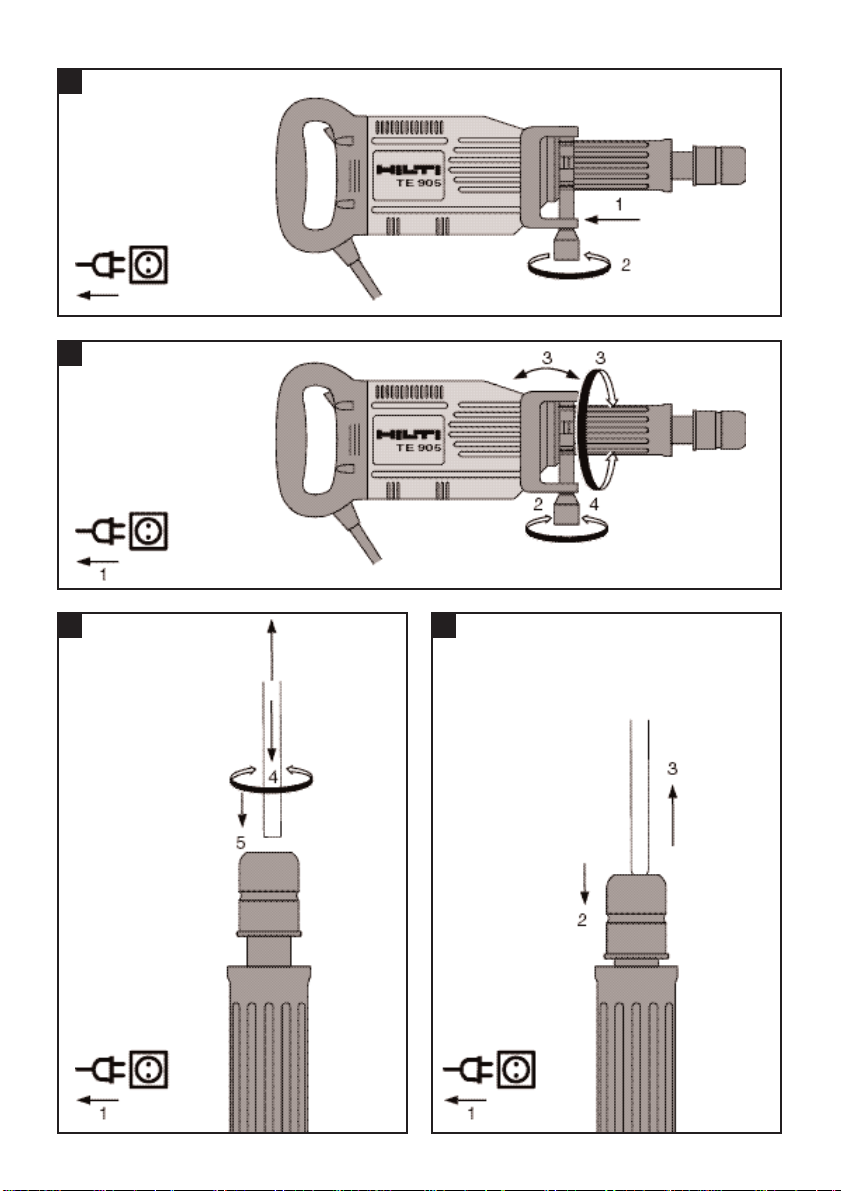
5.3 Fitting the side handle
1. Fit the side handle and side handle clamp onto the
tool.
2. Secure the side handle by tightening the screw knob.
Page 9
5
en
6. Operation
Never use the tool without the side handle.
Use a vice or clamp to secure loose workpieces.
-CAUTION-
● The insert tool may become hot during
use.
● There is a risk of burning the hands.
● Wear protective gloves when changing
insert tools.
6.1 Adjusting the side handle
1. Unplug the supply cord from the mains socket.
2. Slacken the screw knob on the side handle.
3. Bring the side handle into the desired position.
4. Tighten the screw knob to secure the side handle in
the desired position.
6.2 Fitting the insert tool
-NOTE-
The chisel can be locked in the chuck in 6 different positions (in 60°increments).
Flat and shaped chisels can thus always be brought into
the optimum position for the job on hand.
1. Unplug the supply cord from the mains socket.
2. Check that the insert tool connection end is clean and
lightly greased. Clean and grease the connection end
if necessary.
3. Check that the sealing lip on the dust cap is clean and
in good condition. Clean the dust cap if necessary or
replace it if the sealing lip is damaged.
4. Push the insert tool into the chuck and rotate it while
applying light pressure until it engages in the guide
grooves.
5. Push the insert tool into the chuck until it is heard to
engage.
6. Check that the insert tool is held securely by attempting to pull it out of the chuck.
6.3 Removing the insert tool
1. Unplug the supply cord from the mains socket.
2. Open the chuck by pulling back the locking sleeve.
3. Pull the insert tool out of the chuck.
6.4 Chiseling
-NOTE-
When working at low temperatures: The hammering
mechanism works only when the tool has reached a minimum operating temperature. Bring the drill bit into contact with the base material and allow the tool to run under
no load until the minimum operating temperature is
reached. If necessary, repeat this procedure until the
hammering mechanism begins to operate.
6.4.1 Switching on
1. Plug the supply cord into the electric socket.
2. Press the on/off switch.
6.4.2 Switching off
Press the on/off switch.
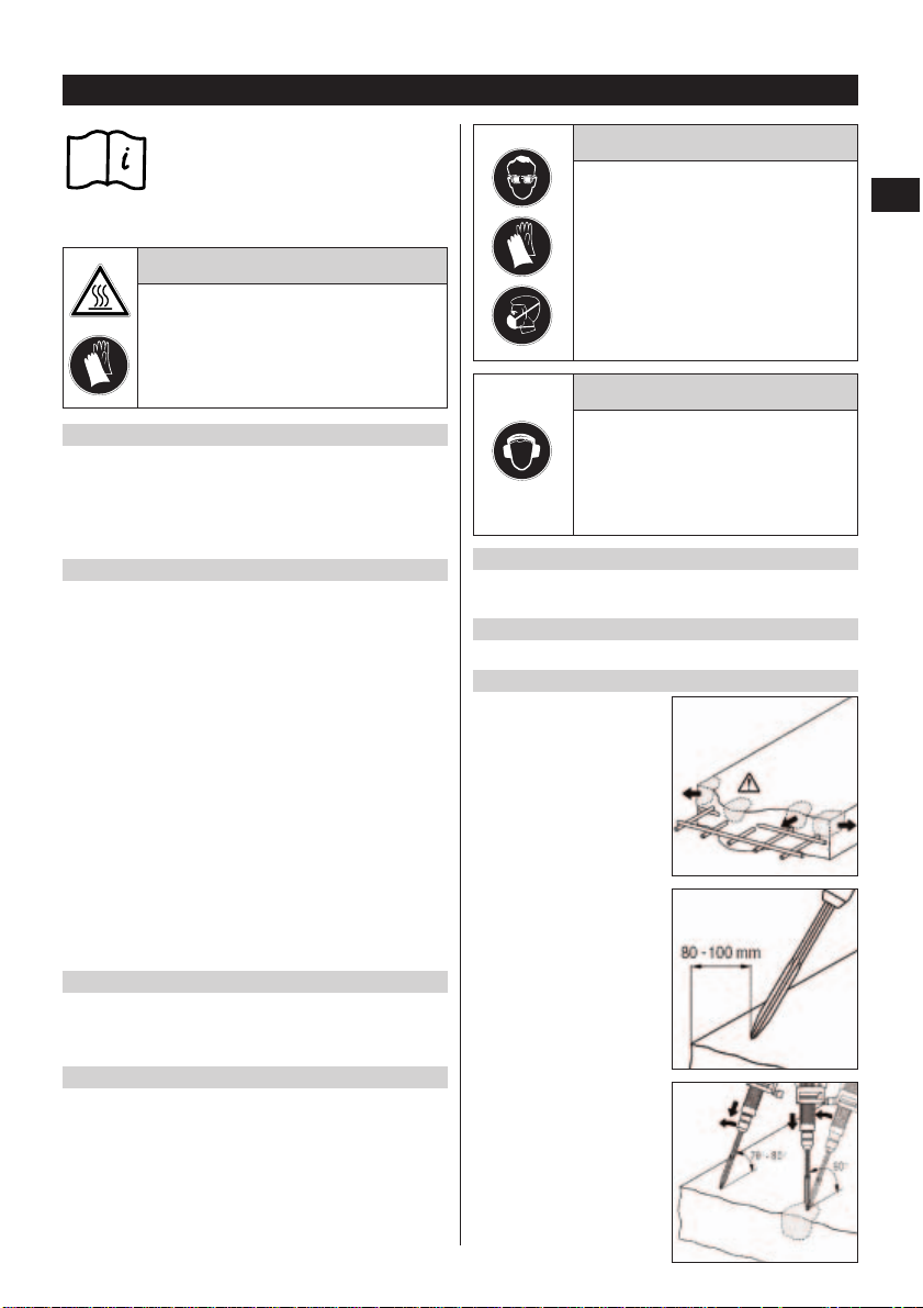
6.4.3 Chiseling tips
Reinforcing bars
Always guide the chisel toward the edge of the material and not toward the reinforcing bar .
Starting chiseling
Position the point of the
chisel approx. 80–100 mm
(3.1–3.9 in) from the edge
of the material.
Chiseling direction
Begin chiseling at an angle
of 70–80° to the concrete
surface, with the tip of the
chisel pointing toward the
edge. Increase the angle to
90°as the chisel penetrates,
thus breaking away material.
-CAUTION-
● Drilling may cause splintering of the
material.
● Splinters may cause injury to parts
of the body and eyes.
● Wear eye protection, protective gloves
and breathing protection if no dust
removal system is used.
-CAUTION-
● The tool and the drilling operation
emit noise.
● Excessive noise may damage the hear-
ing.
● Wear ear protection.
Page 10

Contact pressure
Contact pressure too low:
Chisel jumps about.
Contact pressure too high:
Lower chiseling performance.
Self-sharpening process
Rotate the chisel in the chuck
at regular intervals (ensures
even wear and assists the
self-sharpening process).
Depth of penetration
Polygon chisels break up
and crush the material even
at considerable depth.
6
en
60 - 100 mm
12–15 kg
7. Care and maintenance
Unplug the supply cord from the mains socket.
7.1 Care of insert tools
Clean off dirt and dust deposits and protect your insert
tools from corrosion by wiping them from time to time
with an oil-soaked rag.
7.1.1 Regrinding insert tools
Pointed, flat and wide-flat chisels can be reground when
slightly worn at the tip or cutting edge.
-NOTE-
Avoid overheating the surface of the chisel during grinding (no discoloration).
7.2 Care of the electric tool
The outer casing of the tool is made from impact-resistant plastic. Sections of the grip are made from an elastomer material.
Never operate the tool when the ventilation slots are
blocked. Clean the ventilation slots carefully using a dry
brush. Do not permit foreign objects to enter the interior
of the tool. Clean the outside of the tool at regular intervals
using a slightly damp cloth. Do not use a spray, steam
pressure cleaning equipment or running water for cleaning.
This may negatively affect the electrical safety of the tool.
Always keep the grip surfaces of the tool free from oil and
grease. Do not use cleaning agents which contain silicone.
7.3 Service indicator
The tool is equipped with a service indicator.
7.3.1 The service indicator lights
The carbon brushes have reached the end of their life.
The tool can be operated for a further approx. ten hours
after the service indicator lights, after which the automatic cut-out will be activated. Please return the tool to
a Hilti service center in good time so that it is ready for
use when required.
7.3.2 The service indicator blinks
An electrical fault has occurred.
The tool has been rendered inoperable and should be
returned to a Hilti repair center for servicing.
7.4 Maintenance
Check all external parts of the tool for damage at regular
intervals and check that all controls operate faultlessly.
Do not operate the tool if parts are damaged or when the
controls do not function faultlessly. If necessary , your
electric tool should be repaired at a Hilti repair center.
Repairs to the electrical section of the tool may be carried out only by trained electrical specialists.
7.5 Checks after care and maintenance
After carrying out care and maintenance on the tool, check
that all protective equipment has been refitted and that
all items function faultlessly.
Page 11
7
en
Fault Possible cause Remedy
The tool doesn't start Fault in mains supply Plug in another electric appliance and
check whether it works
Supply cord or plug defective The cord should be checked and, if neces-
sary, replaced by an electrical specialist
On/off switch defective The cord should be checked and, if neces-
sary, replaced by an electrical specialist
No hammering action The tool is too cold Allow the tool to warm up to the minimum
operating temperature (see 6.4 “Chiseling”)
The tool does not achieve Extension cord with inadequate cross Use an extension cord with adequate cross
full power section used section (see 5.1 “Use of extension cords”)
9. T roubleshooting
8. T ools and accessories
TE 905-AVR
TE-S chuck ●
Pointed chisel
Flat chisel
Wide flat chisel
Asphalt chisel
Flexible chisel
Bushing tool
Tamping tool
Earth rod rammer
HSS hanging support system ●
TPS = theft protection system with
TPS-K activation key ●
Page 12

8
en
11. Warranty
Hilti warrants that the tool supplied is free of defects
in material and workmanship. This warranty is valid
so long as the tool is operated and handled correctly,
cleaned and serviced properly and in accordance with
the Hilti Operating Instructions, all warranty claims
are made within 12 months from the date of the sale
(invoice date), and the technical system is maintained. This means that only original Hilti consumables, components and spare parts may be used in
the tool. This warranty provides the free-of-charge
repair or replacement of defective parts only. Parts
requiring repair or replacement as a result of normal
wear and tear are not covered by this warranty.
Under no circumstances will Hilti be obligated for
direct, indirect, incidental or consequential dam-
ages, losses or expenses in connection with, or by
reason of, the use of, or inability to use the tool for
any purpose. Hilti specifically excludes the implied
warranties of merchantability and fitness for a particular purpose.
For repair or replacement, send tool and/or related
parts immediately upon discovery of the defect to the
address of the local Hilti marketing organization provided.
This constitutes Hilti’s entire obligation with regard to
warranty and supersedes all prior or contemporaneous comments and oral or written agreements
concerning warranties.
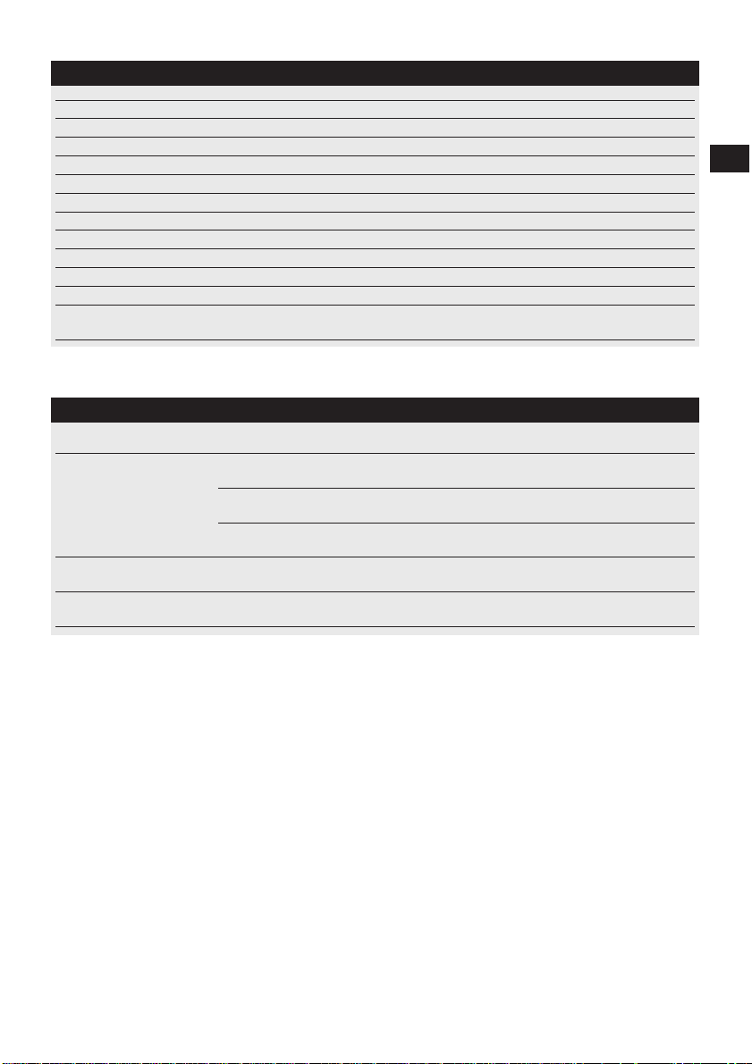
10. Disposal
Most of the materials from which Hilti electric tools are manufactured can be recycled. The materials must be
correctly separated before they can be recycled. In many countries, Hilti has already made arrangements for taking
back your old electric tools for recycling. Please ask your Hilti customer service department or Hilti representative for further information.
Should you wish to return the electric tool yourself to a disposal facility for recycling, proceed as follows:
Dismantle the electric tool as far as possible without the need for special tools. Use absorbent paper to wipe oily
parts clean and to collect any grease that runs out (total quantity approx. 50 ml). This paper should also be disposed
of correctly. On no account should oil or grease be allowed to enter the waste water system or to find its way
into the ground.
The individual parts should be separated as follows:
Part / assembly Main material Recycling
Toolbox Plastic Plastics recycling
Gear housing Plastic with magnesium alloy / brass parts Scrap metal
Bearing plate Magnesium alloy / brass Scrap metal
Grip, side handle Plastic Plastics recycling
Motor housing Plastic Plastics recycling
Fan Plastic Plastics recycling
Motor (rotor and stator) Steel and copper Scrap metal
Supply cord Copper, elastomer Scrap metal
Hammering mechanism parts Steel Scrap metal
Screws, small parts Steel Scrap metal
Page 13

Hilti Corporation
FL-9494 Schaan
Tel.:+423/2342111
Fax: +423/2342 965
www.hilti.com
Hilti = registered trademark of Hilti Corp., Schaan W 2799 1103 25-Pos. 3 1 Printed in Liechtenstein © 2003
Right of technical and programme changes reserved S. E. & O.
376551/B
 Loading...