

Page 1
SDT25
SDT25-15
*304447*
304447
Bedienungsanleitung de
Operating instructions en
Mode d’emploi fr
00 Cover SDT25 P.1 2.4.2004 10:38 Seite 4
Page 2
00 Cover SDT25 P.1 2.4.2004 10:38 Seite 5
1
10
1
2
9
3
4
8
5
6
7
Page 3
00 Cover SDT25 P.1 2.4.2004 10:38 Seite 1
2
3
3
2
3
2
3
3
1
11
4
4
2
3
5
4
5
2
3
7
4
2
6
5
1
1
Page 4
00 Cover SDT25 P.1 2.4.2004 10:38 Seite 7
6
3
1
2
7
11
8
1
2
4
3
Page 5

00 Cover SDT25 P.1 2.4.2004 10:38 Seite 8
9
11
22
10
3
1
1
2
1
3
4
4
Page 6

7
en
It is essential that the operating instructions
are read before the tool is operated for the
first time.
Always keep these operating instructions
together with the tool.
Ensure that the operating instructions
are with the tool when it is given to other
persons.
SDT25 / SDT25-15 decking tool
1. General information
1.1 Signal words and their meaning
-CAUTION-
Used to draw attention to a potentially dangerous situation which could lead to minor personal injury or damage
to the equipment or other property.
-NOTE-
Used to draw attention to an instruction or other useful
information.
1.2 Pictograms
Contents Page
1. General information 7
2. Description 8
3. Tools and accessories 8
4. Technical data 8
5. Safety precautions 9
6. Before use 10
7. Operation 11
8. Care and maintenance 12
9. Disposal 12
10. Warranty 12
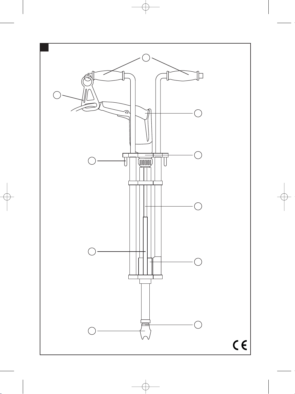
Operating controls and parts
Grips
ST 1800 or ST 18
Clamping bar
Main module
Breach
Nosepiece
Jaws
Magazine
Clamping lever
Supply cord strain relief clasp
These numbers refer to the corresponding illustrations. The illustrations can be found on the fold-out cover
pages. Keep these pages open while studying the operating
instructions.
In these operating instructions, the SDT 25 / SDT 25-15
decking tool is referred to as "the tool".
In addition to these operating instructions, the operating instructions for the electric screwdriver used with
the decking tool must be observed.
Location of identification data on the tool
The type designation can be found on the rating plate
and the serial number on the side of the motor housing.
Make a note of this data in your operating instructions
and always refer to it when making an enquiry to your
Hilti representative or service department.
Type:
Serial no.:
Warning signs
General
warning
Warning:
electricity
Obligation signs
Wear
ear
protection
Wear
eye
protection
Symbols
Read the
operating
instructions
before use.
02 BA SDT25/SDT2515 en 2.4.2004 10:19 Seite 7
Page 7

8
en
2. Description
2.1 Use of the tool as directed
The decking tool is an accessory for the ST 1800 and
ST 18 electric screwdrivers.
The unit (electric screwdriver and decking tool) is used
to drive the recommended metal construction screws
in sheet metal.
Decking tool for self-drilling screws with 10 mm
metal washer (SDT 25) or with 15 mm metal washer
(SDT 25-15).
The working environment may be a construction site of
any kind where metal construction work is taking place.
Use only the specified accessory items.
The general safety precautions listed in the operating
instructions must be observed.
3. Insert tools and accessories
SDT 25 SDT 25-15
Bit holder S-BH 435 DT S-BH 435 DT
Nut set drivers S-NSD 8 DT or S-NSD 5/16 DT S-NSD 10 DT
Magazine Magazine Magazine 15
Bag for collated screws
4. Technical data
Tool SDT 25 SDT 25-15
Weight of tool without screwdriver and screws 3.9 kg 4.0 kg
Weight of tool with screwdriver, without screws 5.7 kg 5.8 kg
ST 1800 / ST 18 screwdriver chuck type
1
/4″ hex. socket
Bit holder / nut set driver connection end
1
/4″ hexagon
Torque settings on the ST 1800 or ST 18 (1–22 Nm)
Height adjustment from 76 cm to 118 cm
Forward / reverse rotation setting on the ST 1800 or ST 18
Screw capacity max. 50 screws max. 40 screws
(2 strips of 25) (2 strips of 20)
Right of technical changes reserved!
2.2 Main applications / torque settings for the ST1800 / ST18 screwdriver
SDT 25
Application Screw drilling capacity Screw type: Europe Torque setting
Sheet metal / sheet metal 2.75 mm S-MD 01Z 4.8×19 M 6–8
Sheet metal / beam 5.5 mm S-MD 03Z 5.5×25 M 8–10
Application Screw drilling capacity Screw type: USA / Canada Torque setting
Sheet metal / sheet metal max. 0.100 in. S-MD 12-14 × 1 M HHWH 15–18
Sheet metal / sheet metal max. 0.100 in. S-MD 10-16 × 7/8 M HHWH 12–18
Sheet metal / sheet metal max. 0.110 in. S-MD 10-16 × 3/4 M HWH #2 5–14
Sheet metal / beam max. 0.175 in. S-MD 10-16 × 3/4 M HWH #3 5–14
Sheet metal / beam max. 0.312 in. S-MD 12-24 × 7/8 M HWH #4 10–12
SDT 25-15
Application Screw drilling capacity Screw type Torque setting
Sheet metal / beam 6 mm S-MD 2310Y 6.3×22 M 10–12
2.3 Items supplied
– SDT 25 or SDT 25-15 decking tool
– Bit holder
– Nut set driver for hex. screws
– Operating instructions
– Packed in a cardboard box
02 BA SDT25/SDT2515 en 2.4.2004 10:19 Seite 8
Page 8

9
en
5. Safety precautions
5.1 Basic information concerning safety
In addition to the information relevant to safety given in
each of the sections of these operating instructions, the
following points must be strictly observed at all times.
When used with an electric tool, the safety precautions
listed in the operating instructions for the corresponding electric tool must be observed.
5.2 Take the necessary precautions to make the
workplace safe
● Ensure that the workplace is well lit.
● Ensure that the workplace is well ventilated.
● Keep the workplace tidy. Objects which could cause
injury should be removed from the working area. Untidiness at the workplace can lead to accidents.
● Use clamps or a vice to secure the workpiece. The
workpiece is thus held more securely than by
hand and both hands remain free to operate the
tool.
● Wear eye protection.
● Wear suitable working clothing. Do not wear loose
clothing, loose long hair or jewelry as these can become
caught up in moving parts. Wear suitable headgear if
you have long hair.
● It is recommended that rubber gloves and shoes or
boots with non-slip soles are worn when working outdoors.
● When working, keep other persons, particularly chil-
dren, outside the range of the tool. Do not permit other
persons to touch the tool. Keep other persons away
from the area in which you are working.
● Avoid unfavorable body positions when working. Work
from a secure stance and always stay in balance.
● To avoid tripping and falling when working, always lead
the supply cord, extension cord and extraction hose
away to the rear.
● Concealed electric cables or gas and water pipes pre-
sent a serious hazard if damaged while you are working.
Accordingly, check the area in which you are working
beforehand (e.g. using a metal detector). Avoid contact between your body and earthed / grounded objects,
such as pipes or radiators. External metal parts of the
tool may become live, for example, when an electric
cable is drilled into inadvertently.
5.3 General safety precautions
● Use the right electric tool for the job. Do not use the
tool for purposes for which it was not intended. Use
the tool only as directed and when it is in faultless condition.
● Avoid contact with rotating parts.
● Use only the original accessories or ancillary equip-
ment listed in the operating instructions. Use of other
insert tools or accessories may present a risk of personal injury.
● Take the influences of the surrounding area into account.
Do not expose the tool to rain or snow and do not use
it in damp or wet conditions. Do not use the tool where
there is a risk of fire or explosion.
● Keep the grips dry, clean and free from oil and grease.
● Always hold the tool with both hands on the grips pro-
vided.
● Operate the tool only as directed and only when it is in
faultless condition.
● When not in use, the tool must be stored in a dry place,
locked up or out of reach of children.
● Take care of your insert tools. You will be able to work
more efficiently and more safely if the insert tools are
kept sharp and clean. Observe instructions on care and
maintenance and on changing insert tools.
● Check that moving parts function faultlessly and that
they are not sticking or damaged. All parts must be
correctly fitted and fulfil all requirements in order to
ensure that the tool operates faultlessly.
● Check the electric tool for possible damage. Protec-
tive devices and any parts that may have suffered slight
damage should be checked for correct operation and
functionality before further use of the electric tool.
Damaged safety devices or other damaged parts should
be replaced or repaired properly by an authorized repair
workshop unless otherwise indicated in the operating
instructions.
● Ensure that all parts of the tool are secured before
transport. Check that all locking mechanisms are tightened.
5.3.1 Mechanical hazards
● The tool may jump back if released suddenly when
under tension (pressed down), presenting a risk of
injury (especially bruising). Release the tool in a controlled manner.
● Take care when the nosepiece is under tension and
the tool is turned upside down. Keep well away from
the tool nosepiece. The nosepiece may jump back suddenly, presenting a considerable risk of injury.
● Follow the instructions concerning care and mainte-
nance.
● Check that the insert tools used are compatible with
the chuck system and that they are secured in the chuck
or gear housing correctly.
02 BA SDT25/SDT2515 en 2.4.2004 10:19 Seite 9
Page 9

10
en
6. Before use
5.4 Requirements to be met by users
● The tool is intended for professional use.
● The tool may be operated, serviced and repaired only
by authorized, trained personnel. This personnel must
be informed of any special hazards that may be encountered.
● Always concentrate on the job you are doing. Proceed
carefully and do not use the tool if your full attention
is not on the job.
5.5 Personal protective equipment
● The operator and other persons in the immediate vicinity
must always wear eye protection and ear protection
while the tool is in use.
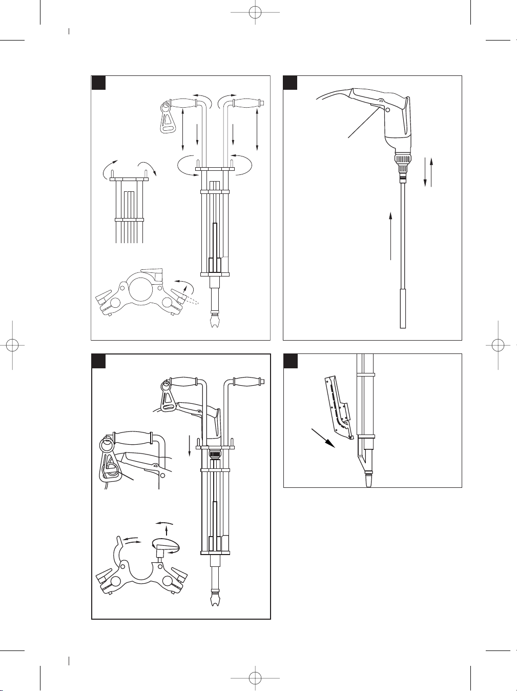
6.1 Assembling the tool and electric screwdriver
6.1.1 Fitting the grips
1. Open the two clamping levers on the main module.
2. Push the two grips into the lower tubular sections
(the grip with the supply cord strain relief clasp on
the right-hand side).
3. Adjust the height and angle of the grips. In order to
ensure that the grips can be clamped securely in position, the grips should not be extended beyond a length
of 118 cm.
4. Secure the grips by closing the clamping levers.
5. Pull the clamping levers out to the front and rotate
them into a position where they will not get caught
on things (preferably pointing toward the inside).
6.1.2 Preparing the electric screwdriver for use
1. Set the ST 1800 or ST 18 to forward rotation (-NOTE-
Screws cannot be driven when the tool is set to the
wrong direction of rotation).
2. Remove the depth gauge from the ST 1800 or ST 18.
3. Fit the bit holder and nut set driver to the ST 1800 or
ST 18.
6.1.3 Mounting the electric screwdriver on the tool
1. Open the clamping lever on the clamping bar of the
main module.
2. Swing the clamping bar into the open position.
3. Guide the front end of the ST 1800 or ST 18 into the
barrel of the main module. The grip must point to the
right so that the supply cord is directed toward the
strain relief clasp.
4. Close the clamping bar.
5. Secure the ST 1800 or ST 18 by closing the clamping lever.
6. Pull the clamping lever out to the front and rotate it
to a position where it will not catch on things or get
in the way.
7. Pass the supply cord through the strain relief clasp
on the grip on the right (feed a loop through from
below and then pass it over the clip).
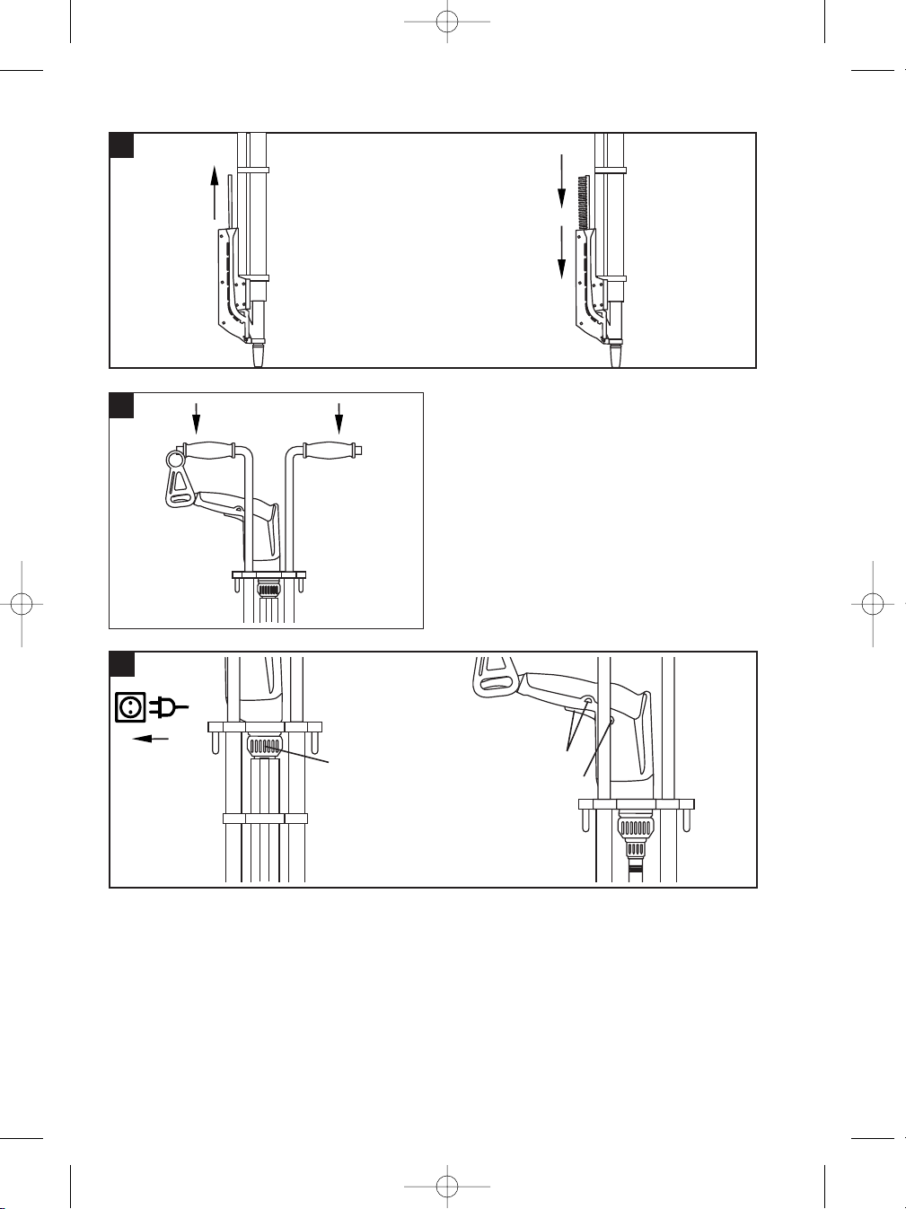
6.1.4 Fitting the magazine
1. Bring the magazine into position at the breach from
behind and then engage it with the upper and lower
tubular sections.
Wear ear
protection
Wear eye
protection
02 BA SDT25/SDT2515 en 2.4.2004 10:19 Seite 10
Page 10

11
en
7. Operation
-NOTE-
Secure the workpiece. Use clamps or a vice to hold the
workpiece securely in position. It is then held more safely and both hands remain free for holding and operating the tool.
7.1 Loading screws into the tool
1. Insert the magazine strip into the magazine from above.
2. Push the magazine strip firmly into the magazine until
all screws have fallen into the magazine. (Two magazine strips of delete 25 screws can be inserted. The
second strip must remain in the tool.)
3. Remove the empty magazine strip from the tool.
7.2 Initial loading operation
1. Press the tool down fully (a screw will become visible at the nosepiece).
7.3 Switching on the electric screwdriver
1. Plug the supply cord into the electric socket.
2. Set the required torque on the ST 1800 or ST 18. (See
section 2.2 - Applications / torque settings). The torque
settings listed are intended as a guideline. The exact
setting should be determined by making test fastenings.
3. Set the ST 1800 or ST 18 to forward rotation (-NOTE-
Screws cannot be driven when the tool is set to the
wrong direction of rotation).
4. Switch on the ST 1800 or ST 18 in sustained operating mode.
7.4 Driving screws
1. Bring the tool nosepiece to the position where the
screw is to be driven.
2. Drive the screw by pressing the tool down fully. (The
tool must be pressed down fully again each time a
screw is to be driven).
3. The tool returns to its outset position under spring
pressure. Always hold the tool securely with both
hands on the grips in order to ensure safe operation.
-CAUTION-
● The screwdriving procedure may
cause the material to splinter.
● Splintering material may injure the
eyes.
● Wear eye protection.
7.5 Driving screws in positions where access is
restricted
1. The tool nosepiece can be rotated through 90° in order
to permit screws to be driven in positions where access
is difficult (tight corners etc.).
7.6 Removing screws from the magazine
1. Push the empty magazine strip back into the tool.
2. Turn the tool upside down (nosepiece pointing upwards).
The screws then slide back into the magazine strip (it
may be necessary to shake the tool).
3. Pull the magazine strip out of the tool.
4. One screw may remain in the tool nosepiece. It can
be removed by opening the retaining jaws in the nosepiece.
7.7 Disassembling and assembling the nut set
driver
Bit holder and nut set driver for hex. head screws.
7.7.1 Disassembly
1. Use a pointed object to press in the pin in the hole in
the nut set driver.
2. Pull the bit away from the bit holder.
7.7.2 Assembly
1. Press in the pin in the bit holder.
2. Push the nut set driver onto the bit holder and check
that it engages (the hole must be in alignment with
the pin in the bit holder).
02 BA SDT25/SDT2515 en 2.4.2004 10:19 Seite 11
Page 11

12
en
8. Care and maintenance
Unplug the supply cord from the electric socket.
Remove the ST 1800 or ST 18 electric screwdriver, bit
holder and bit from the decking tool.
8.1 Care of screwdriving bits
Remove any dirt adhering to the screwdriving bits and
drive spindle and rub these parts with an oily cloth at
regular intervals to protect them from corrosion.
8.2 Care of the tool
The tool can be washed under running water if it has
become very dirty. The tool must then be dried and rubbed
with an oily cloth to prevent corrosion. Always keep the
grip sections of the tool free from oil and grease. Do not
use cleaning agents or lubricants containing silicone.
8.3 Maintenance
Check all external parts of the tool for damage at regular
intervals and check that all controls operate faultlessly.
Do not operate the tool if parts are damaged or when the
controls do not function faultlessly. If necessary, your
electric tool should be repaired at a Hilti repair center.
Repairs to the electrical section of the tool may be carried out only by trained electrical specialists
8.4 Checks after care and maintenance
Check that the tool functions correctly (drive and remove
a screw) after carrying out care and maintenance.
10. Warranty
Hilti warrants that the tool supplied is free of defects in
material and workmanship. This warranty is valid as long
as the tool is operated and handled correctly, cleaned
and serviced properly and in accordance with the Hilti
operating instructions, all warranty claims are made within
12 months (unless other mandatory national regulations
prescribe a longer minimum period) from the date of the
sale (invoice date), and the technical system is maintained. This means that only original Hilti consumables,
components and spare parts may be used in the tool.
This warranty provides the free-of-charge repair or replacement of defective parts only. Parts requiring repair or
replacement as a result of normal wear and tear are not
covered by this warranty.
Additional claims are excluded, unless mandatory
national rules prohibit such exclusion. In particular,
Hilti is not obligated for direct, indirect, incidental or
consequential damages, losses or expenses in connection with, or by reason of, the use of, or inability to
use the tool for any purpose. Implied warranties of
merchantability or fitness for a particular purpose are
specifically excluded.
Send the tool and/or related parts immediately upon discovery of a defect to the local Hilti marketing organisation for repair or replacement.
This constitutes Hilti’s entire obligation with regard to
warranty and supersedes all prior or contemporaneous
comments and oral or written agreements concerning
warranties.
9. Disposal
Most of the materials from which Hilti electric tools are manufactured can be recycled. The materials must be
correctly separated before they can be recycled. In many countries, Hilti has already made arrangements for taking
back your old electric tools for recycling. Please ask your Hilti customer service department or Hilti representative for further information. Should you wish to return the electric tool yourself to a disposal facility for recycling,
proceed as follows: Dismantle the electric tool as far as possible without the need for special tools.
The individual parts should be separated as follows:
Part / assembly Main material Recycling
Grips Plastic Plastics recycling
Magazine Plastic Plastics recycling
Main module Steel, aluminium and plastic Scrap metal / plastics recycling
Screws, small parts Steel Scrap metal
02 BA SDT25/SDT2515 en 2.4.2004 10:19 Seite 12
Page 12

*304447*
Hilti Corporation
FL-9494 Schaan
Tel.: +423/ 2342111
Fax: +423 /23429 65
www.hilti.com
Hilti = registered trademark of Hilti Corp., Schaan W 2824 1203 0,5-Pos. 1 1 Printed in Liechtenstein © 2003
Right of technical and programme changes reserved S. E. & O.
304447 / C
00 Cover SDT25 P.1 2.4.2004 10:38 Seite 3
 Loading...