

Page 1
1
2
3
PD 25 quick-start instructions
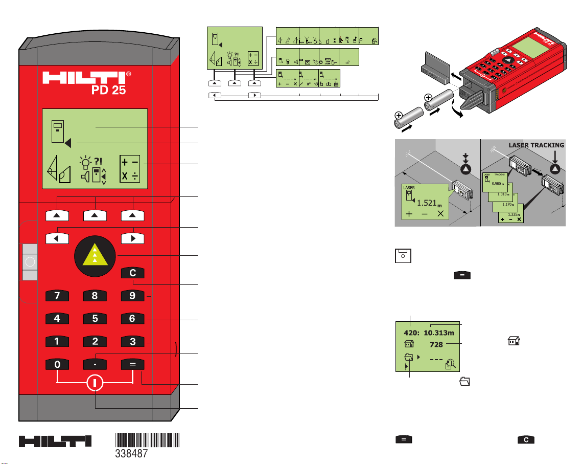
Display and control panel
Button functions
Memory functions
Display functions
Type AA
“Clear” button
for clearing the display (also
individual place values) and for cancelling a function
(press briefly to go back step by step,
press long to go back to start menu)
Button for
switching on and taking measurements
Press twice briefly: T ake measurement
Press once (long press): Begin continuous
measurement (tracking)
Main menu
Graphical display
Buttons for menu selection
Show menu / select function
Status indicator (measuring reference point)
Scroll forward / back in the selected menu
Switch the tool off
“Equals” button,
for executing a calculation,
confirming an entry or accening the memory menu
Numeric keypad (0...9) for entering identification
codes and values used in calculations
“Decimal value” button for entering decimal values
or for setting units to entered values
The measurement can be saved and
identified (tagged).
On pressing the button (after taking a
measurement or, additionally, after a calculation), the
memory menu is shown in the display:
The group and measurement codes can be entered
using the numeric keypad (0...9).
The memory operation is confirmed by pressing the
button or cancelled by pressing .
Group code
e.g. for identification of the
jobsite (max. 3-digit number)
Measurement
Memory locations 0-999 (assigned by the PD 25)
Measurement code e.g. type of measurement
(max. 3-digit number)
*338487*
338487
Page 2
active
inactive
active
inactive
Note the CODE!
Enable data saving
Disable data saving
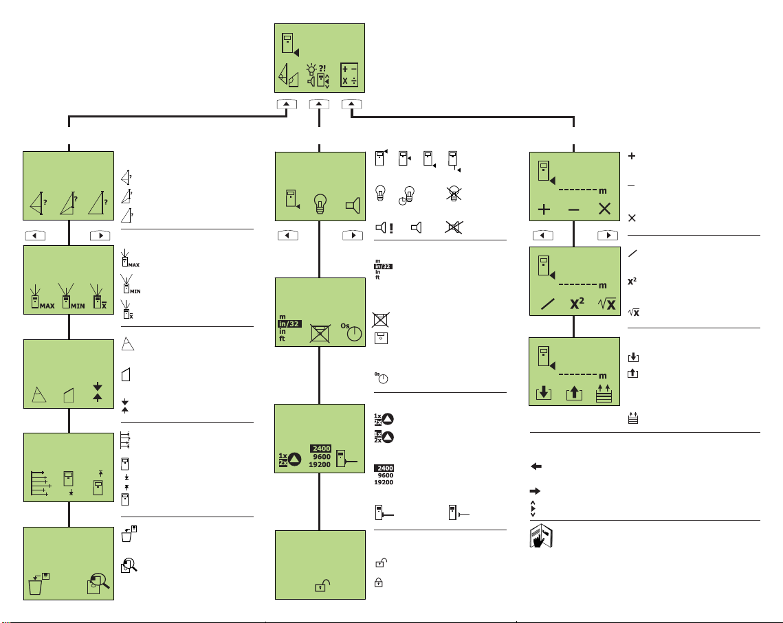
PD 25 menu overview
Special measuring functions Settings Calculation and memory functions
Determine lengths of sides, or
parts of sides, of a triangle
Triangle calculations
(height, angle, area)
Set out distances
Pitched roof calculations
(length of inclined section,
angle, area of gable end)
“MIN / MAX” function
Total length
Part length
Opposite side
Determine maximum
distance
Mean value measurement
Determine shortest
distance
Mean value from several
measurements (max. 99)
Shift measuring reference
point back
Shift measuring reference
point forward
Delete all data from
memory
Show or delete memory
contents (max. 1000
memory locations with
identification tags)
Addition
Subtraction
Multiplication
Reference point on tool
Display illumination
Beep signal during operation
Units displayed
[m] / Feet [’] Inch [’’] /
Inch [in] / Feet [ft]
Memory with identification tags
(max. 1000 values)
Self-timer
(0 / 2 / 5 / 10 / 20 sec.)
Division
Squares
Square roots
Scroll (0-8)
Manual intermediate memory
Last 10 distance
measurements
Save (0-9)
Recall (0-9)
15s
only when measuring
permanently
Laser beam on
Log function
Switch-on lock
Baud rate
for data transfer
Navigation aids
Scroll back
Scroll forward
Scroll up or down within a function
For further information, please refer to the PD
25 operating instructions.
Hilti = registered trademark of Hilti Corp., Schaan
Right of technical and programme changes reserved
W2403 0500 6 english 9 Printed in Liechtenstein © 2000 S.E.&O.
Page 3

PD25
Operating instructions
GB
*334080*
334080
Page 4
2
1
2
3
ON
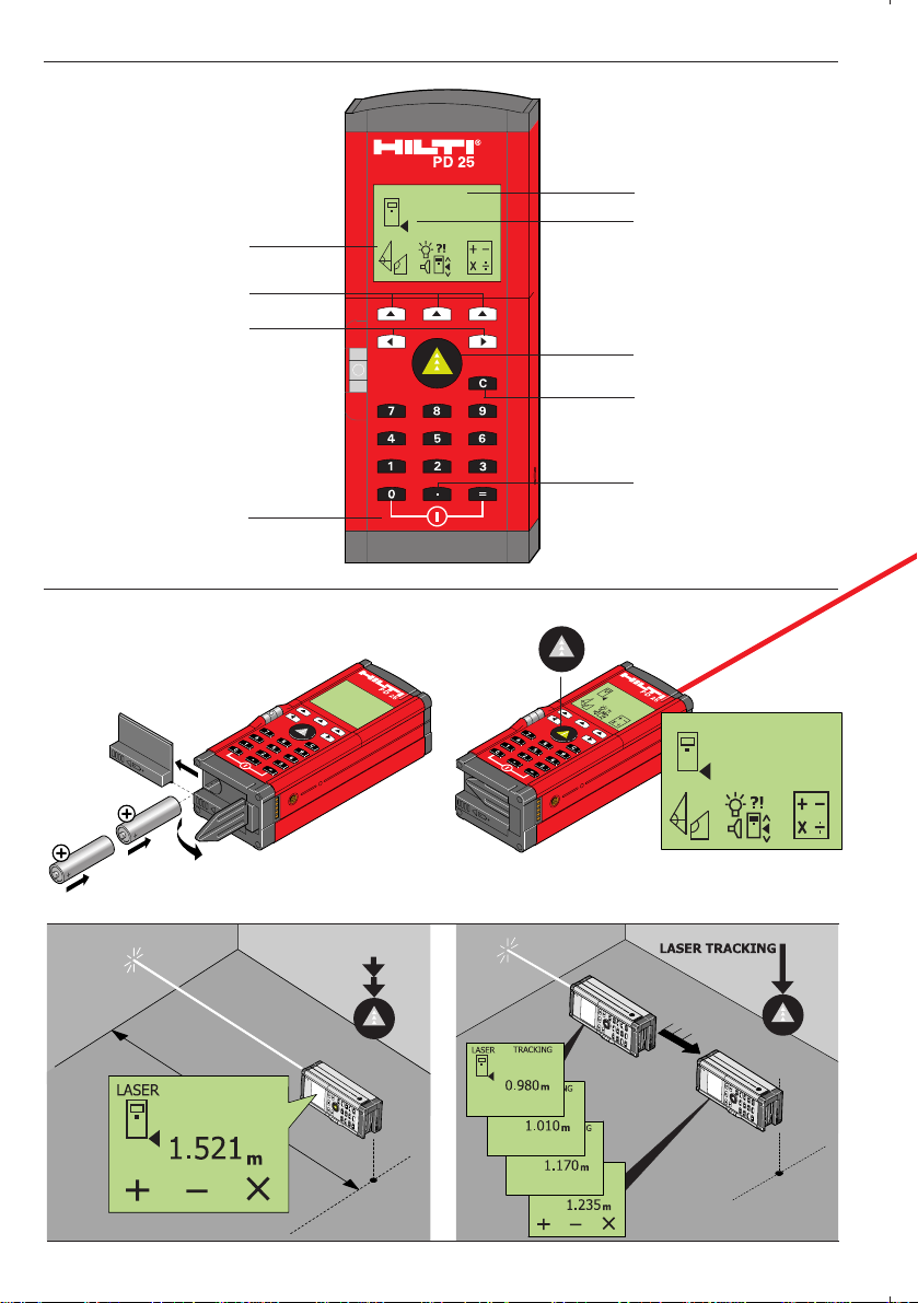
PD 25 quick-start instructions
“Clear” button
“Decimal value”
button
Switch off
Switch on and take
measurement
Main menus
Scroll through menu
Graphical display
Select menu
Reference point
indicator
(Measurement
reference)
Page 5
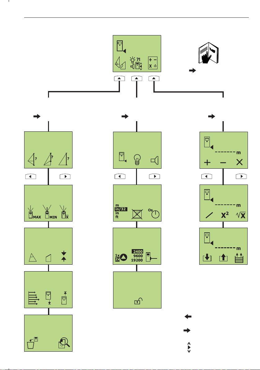
PD 25 menu overview
3
PD 25 quick-start instructions
Page 22
Special measuring
functions
Settings
Calculation and
memory functions
Page 23 Page 25 Page 31
Navigation aids
Scroll forward
Scroll back
Scroll up or down
Page 6
4
PD 25 laser range meter
PD25 operation instructions
In addition to the instructions for use, this manual also contains
important safety information (see “Safety precautions” section).
Please read these instructions carefully before using the tool and
give them to all other persons to read before they use the tool for
the first time.
We recommend that the operating instructions are kept together
with the tool.
Symbols used
Product identification
The type designation and serial number can be found on a nameplate attached to the rear of the product. Make a note of this information in the operating instructions and always refer to it when
addressing any enquiries to our agents or service department.
Type: PD 25
Serial no.: ____________________
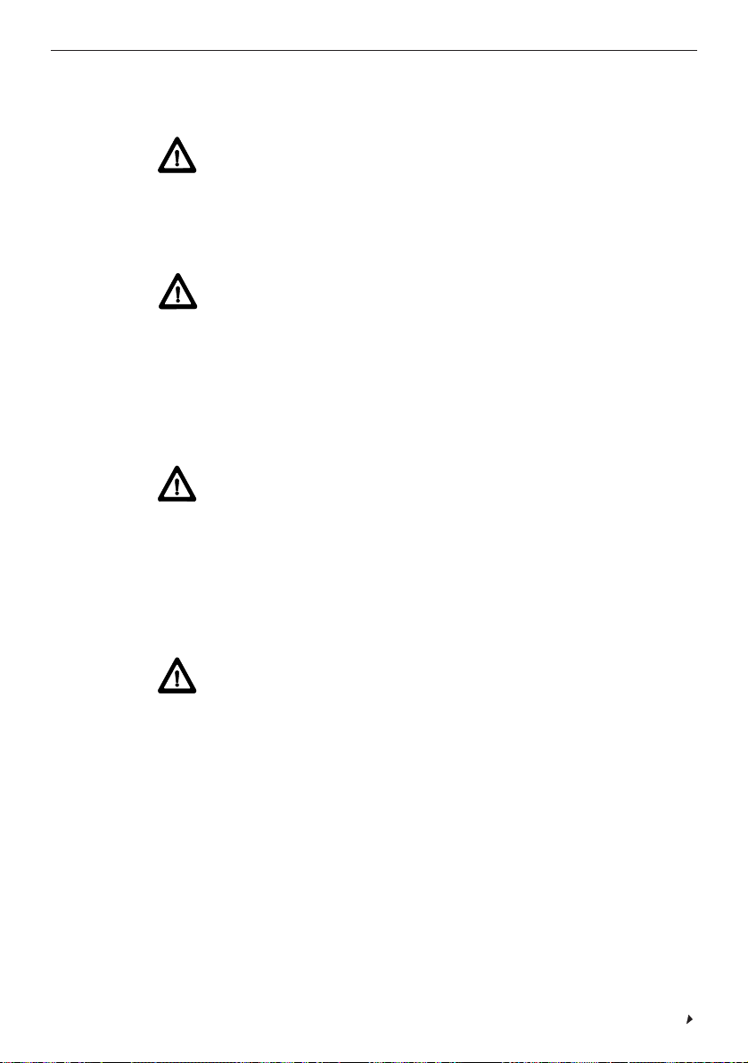
The symbols used in these operating instructions have the following
meanings:
Warning
Operating risk or misuse which may lead to serious personal injury
or death.
Operating risk or misuse which may lead to only minor personal
injuries, but to serious material, property or environmental damage.
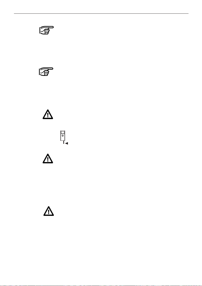
Information to help the operator use the product in a technically
correct and efficient manner.
Page 7

5
Contents
Contents
Continued
1. Product information ..................................................................7
Description of functions ....................................................................7
Features of the PD 25 ......................................................................8
Display and control panel..................................................................9
Button functions ................................................................................9
Technical data ................................................................................10
Items supplied ................................................................................12
2. Safety information....................................................................13
Please read this now!......................................................................13
Purpose ..........................................................................................13
Intended uses..................................................................................13
Examples of misuse ........................................................................13
Operating limits................................................................................14
Environment ....................................................................................14
Division of responsibilities................................................................14
Operating risks ................................................................................14
Disposal ..........................................................................................18
Laser classification..........................................................................19
Information plate..............................................................................20
Electromagnetic compatibility (EMC)..............................................21
3. Operation.................................................................................. 22
Inserting the batteries......................................................................22
Menu selection and settings............................................................22
Special measuring functions............................................................23
Setting preferences..........................................................................25
Calculation and intermediate memory functions..............................31
Entering numerical values ..............................................................32
4. Working with the PD 25 .......................................................... 33
Measuring distances ......................................................................33
Measuring using the folding pointer ................................................34
Measuring using the self-timer ........................................................35
Measuring with the aid of a target object..........................................36
Taking measurements from various surfaces ..................................36
Continuous measurement (tracking) ..............................................37
Calculation......................................................................................38
Addition / subtraction (distances) ....................................................38
Multiplication (areas / volumes) ......................................................39
Page 8

6
Contents
Contents, continued
Measuring distances indirectly........................................................40
Determining the total length of the side of a triangle........................40
Measuring part of the length of the side of a triangle ......................41
Determining the length of the opposite
side of a triangle according to the Pythagoras principle ..................42
Continuous measurement “tracking MAX” ......................................44
Continuous measurement “tracking MIN”........................................45
Measuring the mean value ..............................................................46
Triangle calculations ......................................................................46
Determining the height, angle or area of a triangle..........................46
Pitched roof calculations..................................................................48
Setting out distances ......................................................................49
Calculating the mean value from several measurements................51
Shifting the measuring reference point............................................52
Memory ..........................................................................................53
Deleting memorised values ............................................................53
Searching for, identifying or deleting
measurements saved in memory ....................................................54
5. PD25 server (option) ................................................................55
PD25 server menu overview ..........................................................55
Description of PD 25 server functions..............................................55
Installing and setting up the PD 25 server software ........................57
Connecting the PD 25 to a PC ........................................................58
The PD 25 server software in use ..................................................59
PD 25 server software troubleshooting ..........................................60
Uninstalling the PD 25 server software ..........................................60
6. Care, transportation and storage............................................61
Cleaning and drying........................................................................61
Storage ..........................................................................................61
Transportation ................................................................................61
7. Symbols displayed ..................................................................62
8. Measuring equipment inspection............................................63
9. Accessories ..............................................................................64
10. FCC statement (applicable in US) ........................................66
11. EC declaration of conformity ................................................66
12. Warranty..................................................................................67
Page 9
7
1. Product information
1. Product information
Description of functions
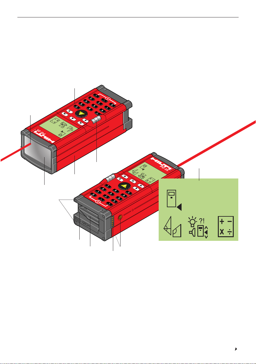
The Hilti PD 25 is a laser range meter. It uses a laser beam to measure distances within the 0.3 m - 100 m range with high precision.
1 Laser exit aperture
2 Numeric keypad
3 Receiving optics
4 Plastic casing
5 Bubble
6 Battery compartment
7 Spike (folding)
8 RS 232 interface
9 Two tripod mounting threads
10 Menu-driven graphical display
11 Four metal contact points for precise measurements
Continued
1
2
5
4
11
6
3
7
9
8
10
Page 10
8
1. Product information
Description of functions, continued
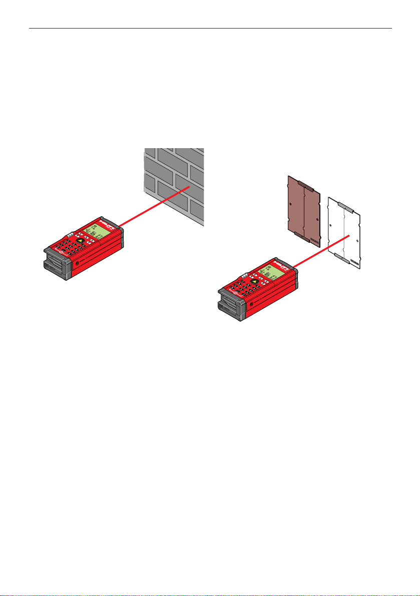
The point from which the measurement is taken is clearly identified
by the red spot. The range of the tool depends on the reflectance
and finish of the target surface.
When reflectance of the target is good:
- Target the object directly
When reflectance of the target is unsuitable:
Use the P A411 target plate.
- White side, when reflectance is
excessive.
- Brown side, when reflectance is too low.
- Compact and functional design
- Simple, self-explanatory menu selection and menu settings
- One-man, hand-held operation for speed of use
- Large display (can be illuminated)
- The last nine measurements can be memorised.
- Addressable, intermediate memory (10 values)
- Memory capacity for 1000 values, with group codes and identification tags
- Numeric keypad
- Built-in calculation functions
- Function menus with various special measuring functions
(triangle calculations, mean values, tracking, etc.)
- RS 232 interface for transferring data to a PC, etc.
- Built-in theft deterrent
- Switches off automatically
- Built-in bubble level
- Tripod mount
(Optional: P A450 tripod adaptor with fine adjustment of the Xand Y -axes)
Features of the PD 25
Page 11
9
1. Product information
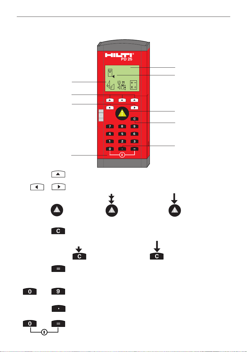
Button functions
Select menu or function
Scroll through active menu
“Clear” button for resetting the display (also individual place values) and for cancelling a function
Switch the
tool on
Short press: One step
back
Long press: Back to main
menu
Press twice (short
press): Take
measurement
Press once (long
press):
Continuous
measurement
(tracking)
Execute calculation, confirm entry or show memory menu
Numeric keypad (0...9) for entering value identification tags and
values used in calculations
“Decimal value” button for entering decimal values or calculations
using other units or without units.
Switch the tool off
Display and control panel
...
“Clear” button
“Decimal value”
button
Switch off
Switch on and take
measurement
Main menus
Scroll through menu
Graphical display
Select menu
Measuring reference point indicator
Page 12

10
1. Product information
T echnical data
Measuring range
0.3 to over 100 m (1 to over 300 ft)
Typical measuring range without target plate:
Drywall panel, white 70 m (210 ft)
Concrete, dry 50 m (150 ft)
Brick, dry 50 m (150 ft)
The maximum range depends on:
- Reflectance of the target surface
- Brightness of ambient light
Use the Hilti P A411 target plate if measurement is impossible.
Accuracy
± 3 mm for individual measurement @ 23° C
(± 0.1 in for individual measurement @ 73° F)
± 5 mm @ 0° C ... +50° C (± 0.2 in @+32° F ... 122° F)
± 7 mm @ –10° C ... +50° C (± 0.3 in @14° F ... 122° F)
Smallest unit displayed 1mm (1/32 in)
Beam diameter
< 6 mm @ 10 m (< 0.2 in @ 30 ft)
< 30 mm @ 50 m (< 1.2 in @ 150 ft)
< 60 mm @ 100 m (< 2.4 in @ 300 ft)
Operating modes
• Individual measurement
• Continuous measurement
• Calculation
Operating status indicator
Liquid crystal display indicating individual operating modes and
operating status
Laser
Visible, 620-690 nm, laser class 2 (IEC825-1), class II (FDA21
CFR); output power: <1 mW
Power supply (3 V DC)
Type: AA (LR6, AM3, mignon)
Standard: 2 alkaline primary cells
Optional: rechargeable NiCd, NiMH
Battery condition
Awarning is displayed when battery voltage is low.
Continued
Page 13
11
1. Product information
T echnical data, continued
Automatic cut-out Laser: 25 sec. Tool: 5 min
Battery life at 25° C [+ 77° F]
Max. no. of measurements with a duration of 5 seconds
Alkaline: 4000 NiCd: 2000 NiMH: 3000
Operating temperature
–10° C ... +50° C (14° F ... 122°F)
Storage temperature
–30° C ... +70° C (–22° F ... 158°F)
Protection class
Dust and splash-proof, IP54 as per IEC 529 standard
Mounting points
1/4‘‘ Whitworth internal thread
1 on the side and 1 underneath (standard camera tripod thread)
Weight
380 g (without batteries)
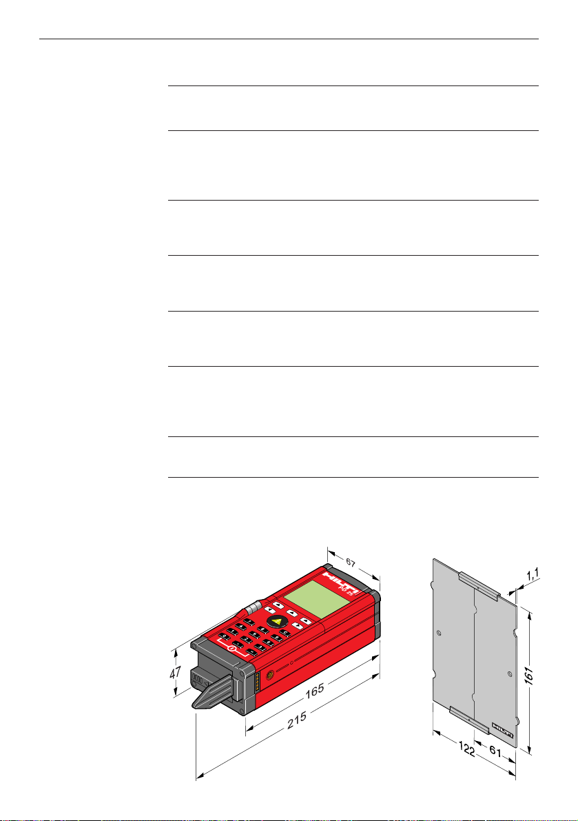
Dimensions
165 x 67 x 47 mm (6.5" x 2.6" x 1.8")
P A411 target platePD25Illustration
showing
dimensions [mm]
Page 14
12
1. Product information
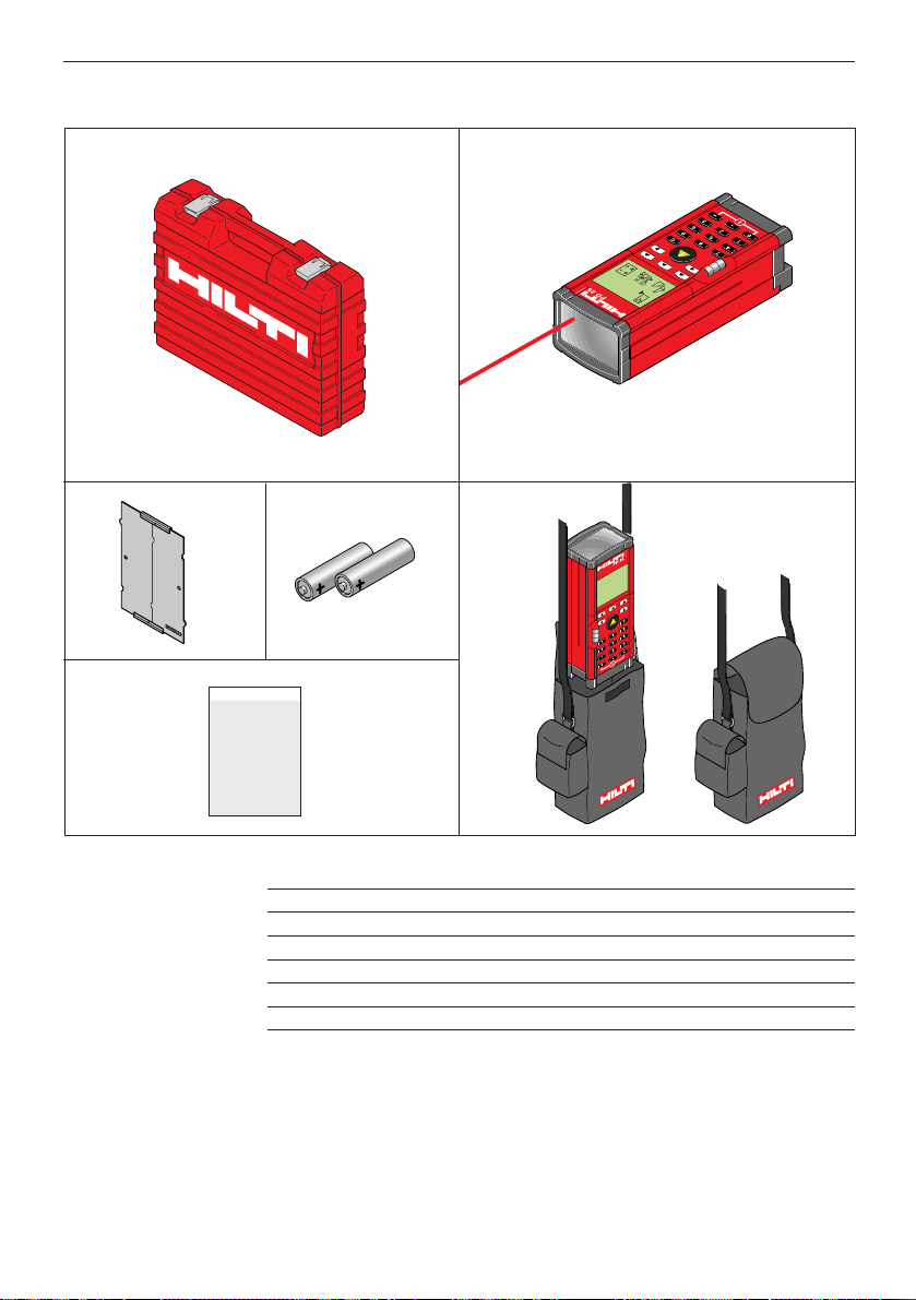
Items supplied
No. Qty. Designation
1 1 PD 25 toolbox
2 1 PD 25 laser range meter
3 1 P A411 target plate
4 2 Type AAbatteries
5 1 PD 25 carrying case
6 1 Operating instructions
PD 25
12
3
4
6
5
Page 15

13
2. Safety information
2. Safety information
Please read this now!
This information is intended to enable owners and users of the Hilti
PD 25 to identify any operating risks in good time, i.e. to eliminate
any such risks in advance where possible.
The owner of the tool must ensure that these instructions are understood and followed by all users.
Purpose
The Hilti PD 25 is intended for the following range of applications:
• Measuring distances
• Calculation of areas, volumes, hypotenuse and angles
• Addition and subtraction of lengths
• Multiplication, division, squares and square roots of measured
values
• Setting out distances
• Saving measurement data
• Special measuring functions
Intended uses
• Use of the product without prior instruction
• Use of the product outside its operating limits
• Rendering safety devices ineffective or removing notices and
warning signs
• Opening the product unless expressly permitted in certain cases
(e.g. to replace the batteries)
• Making conversions or modifications to the product, unless
expressly approved by Hilti
• Deliberately dangerous or careless behaviour on scaffolding,
when climbing ladders or when taking measurements in the vicinity of operating machinery or the exposed parts of machines or
other equipment
• Aiming directly at the sun or other powerful source of light
• Deliberately dazzling other persons
• Use of remote mode with a personal computer that is not earthed
/ grounded (e.g. battery-powered laptop that is not earthed /
grounded)
Examples of misuse
WARNING
Misuse may lead to injury , malfunction and damage to property.
The owner must inform the user of the operating risks associated
with the equipment and the corresponding safety precautions.
The PD 25 laser range meter may be operated only when the user
has received prior instruction.
Page 16

14
Operating risks
WARNING
Use of the product without instruction or with incomplete instruction
may lead to errors by the operator or misuse and thus to accidents
resulting in serious personal injury , pecuniary damage or damage to
property and the environment.
Preventative measures
All users must observe the safety information issued by the manufacturer and the owner’s instructions.
Continued
2. Safety information
Intended uses, continued
Operating limits
WARNING
The owner is responsible for the correct use of the equipment, the
use of the equipment by his employees, their instruction and the
operating safety of the equipment.
The owner has the following obligations:
• To ensure that he has understood the safety information on the
product and the information contained in the operating instructions.
• To be aware of the locally applicable industrial accident prevention regulations.
• To notify Hilti immediately of any safety-related defects or deficiencies in the equipment.
The product is suitable for use in atmospheres permanently habitable by humans. It must not be used in corrosive or explosive environments. Exposure to rain for short periods during use is permissible.
See “Technical data” section.
Environment
Responsibility of the manufacturer of the original equipment,
Hilti Corporation, FL-9494 Schaan (subsequently referred to as
“Hilti”)
Hilti is responsible for supplying a technically safe product in faultless
condition, including operating instructions and original accessories.
Examples of misuse
Page 17
15
2. Safety information
Intended uses, continued
Operating limits, continued
WARNING
Care must be taken to avoid incorrect measurements.
Preventative measures
Keep the receiving lens clean. It should be cleaned at regular intervals.
See: “Cleaning and drying”.
WARNING
Take care to avoid incorrect measurements caused by using a
defective product or a product which has been dropped or subjected
to any other inadmissible stresses or changes.
Preventative measures
Take measurements periodically to check the accuracy of the product, particularly after it has been exposed to excessive stresses
and before and after important measuring tasks.
WARNING
Failure to adequately cordon off the area in which you are measuring may lead to dangerous situations in road traffic, on building
sites or in industrial plants, etc.
Preventative measures
Always ensure that the area in which you are carrying out measuring work is properly cordoned off. Observe the statutory accident
prevention regulations and road traffic regulations of the applicable
country.
WARNING
Taking measurements from surfaces with low reflectance surrounded by areas with high reflectance may lead to measurement errors.
Preventative measures
Take measurements from the brown side of the Hilti P A411 target
plate when the PD 25 is used at the limit of its range.
Continued
Page 18
16
2. Safety information
Operating limits, continued
Note
Opening the product without authorisation will not only invalidate the
warranty , it may also cause malfunctions and measuring errors.
Preventative measures
Do not open the product. Only the battery compartment cover
should be opened (slid to the side) when replacing the batteries.
Note
If the equipment is not used for lengthy periods, there is a risk of it
being damaged by leaking batteries.
Preventative measures
Remove the batteries if you do not intend to use the equipment for
some time.
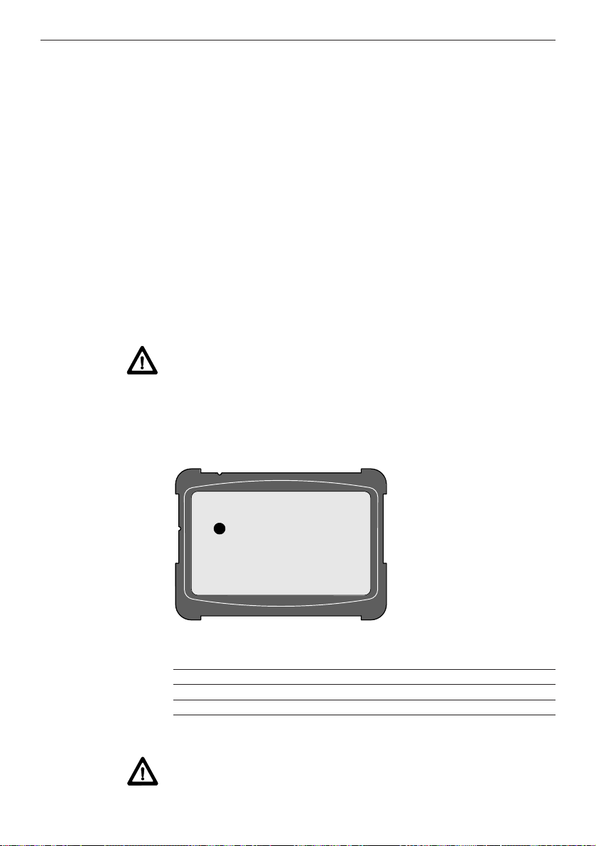
Warning
At regular intervals or before measuring, check that the folding pointer functions correctly .
The symbol illustrated is shown in the display .
Warning
Using the P A421 telescopic sight to view the directly reflected beam
from the PD 25 is hazardous to the eyes when the tool is aimed at
surfaces with mirror-like reflectance or which cause unexpected
reflections (e.g. mirror, metal surfaces, window panes, prisms).
Preventative measures
Do not aim the telescopic sight at surfaces with mirror-like reflectance or which cause unexpected reflections.
Warning
The laser beam can be set to “laser beam permanently on”, thus
possibly dazzling other persons when the tool is switched on unintentionally or handled without due care.
Preventative measures
When the tool is used in this operating mode, ensure that other persons cannot be dazzled.
Page 19
17
2. Safety information
Operating limits, continued
Note
The tool has an accuracy of ± 3 mm at room temperature. In order
to achieve this accuracy , also with calculations, measurements
should be taken carefully .
Note
Different measuring reference points can be selected. To achieve
accurate results, ensure that the correct measuring reference point
on the tool has been selected.
Warning
When taking measurements from a tripod in directly opposite directions (pivoting the tool through 180°), failure to select the correct
measuring reference point may be a cause of error.
Preventative measures
Set the measuring reference point to the tripod axis.
Check the symbol shown in the display:
Page 20

18
2. Safety information
Disposal
WARNING
Improper disposal of the equipment may lead to the following:
• Burning of plastic components generates toxic fumes which may
present a health hazard.
• If damaged or exposed to very high temperatures, batteries may
explode, causing poisoning, burns, acid burns or environmental
pollution.
• Careless disposal enables unauthorised persons to make improper use of the equipment, which may lead to serious injury to
themselves or a third party and to pollution of the environment.
Preventative measures
Most of the materials from which Hilti tools are manufactured can be
recycled.
The materials must be correctly separated before they can be recycled.
In many countries, Hilti has already made arrangements for taking
back old tools for recycling.
Ask your Hilti customer service department or Hilti representative
for further information. Please help to protect our environment.
Part, assembly Main material Recycling
Casing, keypad Plastic Plastics recycling
toolbox, target plate,
carrying case
Measuring module, V arious Electronics scrap
electronics or scrap metal
Screws, small parts Steel Scrap metal
Batteries V arious Disposal centre
Page 21
19
2. Safety information
Laser classification
The Hilti PD 25 generates a visible laser beam which is emitted from
the front side of the tool.
The product conforms to laser class 2 as per:
• IEC825-1: 1993 “Safety of laser equipment”
• EN60825-1: 1994 “Safety of laser equipment”
The product conforms to laser class II as per:
• FDA21CFR Ch.I §1040 :
1988 (US Department of Health and Human Service, Code of
Federal Regulations)
Laser class 2 / II products
Do not look into the laser beam and never aim it at other persons.
Protection of the eyes is normally ensured by defensive reactions
including the eyelid closure reflex.
WARNING
Looking directly into the beam with optical aids (e.g. binoculars or
telescopes) can be dangerous.
Preventative measures
Never look into the beam using optical aids.
Applicable standard: IEC825-1:1993 FDA 21CFR
EN60825-1:1994 Ch.I §1040:1988
Beam divergence: 0.16 x 0.6 mrad 0.16 x 0.6 mrad
Pulse duration: 1x10⁻⁹s 1x10⁻⁹s
Max. power output: 0.95 mW ±5% 0.95 mW ±5%
Warning
The product should be repaired at a Hilti-approved service centre
only.
Laser exit aperture
Page 22

20
2. Safety information
Information plate
All product identification data and warnings concerning the use of
the product can be found on the rear of the Hilti PD 25.
Page 23

21
2. Safety information
Electromagnetic compatibility (EMC)
Electromagnetic compatibility refers to the ability of the Hilti PD 25
to function correctly in an environment where it is exposed to electromagnetic radiation and electrostatic discharge, without causing
electromagnetic interference to other devices.
WARNING
There may be a possibility of interference with other equipment due
to electromagnetic radiation.
Although the Hilti PD 25 complies with the strict requirements of the
relevant directives and standards, Hilti cannot entirely rule out the
possibility of interference with other equipment.
WARNING
Measurements may exceed tolerances in the event of interference
caused by electromagnetic radiation.
Although the Hilti PD 25 complies with the strict requirements of the
relevant directives and standards, Hilti cannot entirely rule out the
possibility of the Hilti PD 25 being subject to interference caused by
very intense electromagnetic radiation, e.g. in the immediate vicinity
of radio transmitters, radio communications equipment, diesel generators, etc.
Check the readings for plausibility when measuring under these
conditions.
Page 24

22
Menu selection and settings
Navigation aids
3. Operation
3. Operation
Inserting the batteries
Symbol
displayed
Low battery voltage - insert new batteries
2x type AA(LR6 / AM3 / Mignon)
Always replace the complete set of batteries.
- Do not mix old and new batteries.
- Do not mix batteries of different makes or types.
- Use only undamaged batteries of an approved type.
When rechargeable batteries are used, each pair of batteries must
be:
- of the same make and the same type.
- of the same age and charged to the same level.
When one of the navigation symbols is dis-
played, the button positioned below it can
be used to navigate through the correspon-
ding menu.
1
2
3
Buttons for selecting
menu items
Scroll through
selected menu
Indication of reference point selected
Main menu
Take measurement
Reset display /
cancel function
Scroll back
Scroll forward
Scroll up or down
Page 25

23
Special measuring functions
Measuring distances indirectly
Triangle calculations
«MIN / MAX» function
Determining
mean
values
Measuring the complete length of a side of a triangle
e.g. measuring a height indirectly
Measuring part of the length of a side of a triangle
e.g. measuring the height of a floor level of a building
Using Pythagoras to determine the length of the opposite side of a
triangle
e.g. measuring the height of a building
To determine the maximum distance
e.g. diagonals
To determine the shortest distance
e.g. normal distance (i.e. at right angles to the distance to be determined) or, respectively, determining right angles
When measurement is started, eight measurements are taken one
after the other and the mean value then indicated.
Determining the height, angle and area of a triangle
Pitched roof calculations
Determining the length of the sloping section, its angle and the area
of the gable end
Continued
3. Operation
Page 26

24
Special measuring functions, continued
Setting out distances
For setting out distances
Mean value from several measurements
Calculates the mean value from measurements taken consecutively
(max. 99 measurements)
Shifting the measuring reference point
Erasing memory
Indicating the memory capacity in use or deleting from memory
To the front
The set value or measured value serves as the new reference
(i.e. zero point shift). All measurements are then taken from the reference point set as long as the tool is used as indicated in this menu.
To the rear
Deletes all data from memory
Memory location
0-999
(assigned by the
PD 25)
Measurement
Group code, e.g. for identification of the jobsite (max. three-digit number)
Measurement code, e.g. type of measurement (max. three-digit number)
3. Operation
Used to display memory contents or to delete values held in
memory (memory capacity for 1000 values). Measurement values
can be identified by customer’s defined identification tags in the
form of max. three-digit group and / or measurement codes.
The numeric keypad (0 ... 9) is used to enter the group codes and
measurement identification codes.
Page 27

25
Setting preferences
Measuring reference point on the tool
Units shown in display
Front edge of tool
Tripod axis
Rear edge (i.e. standard)
End of pointer
This is indicated when the pointer is
folded out (e.g. for taking measurements from the corner of a room).
Display illumination
On permanently
Off
The display illumination switches itself off automatically 15 seconds
after:
- the last press of a button, or
- a measurement is taken.
[m] metric system
Feet [‘] inches [“] and fractions in increments of 1/32
Inches [in] with decimal place
Feet [ft] with decimal place
Beep signal when operated
Abeep signal is
emitted when:
- a measurement is
taken,
- an error occurs
Off
Abeep signal is
emitted when:
- a button is pressed,
- a measurement is
taken,
- an error occurs
Continued
3. Operation
Page 28

26
Setting preferences, continued
Memorised values (max. 1000 values)
- The value can be saved and identified.
- On pressing the button (after taking a measurement or
after a calculation) the memory menu is shown in the display.
- Do not save in memory.
Memory settings
- The numeric keypad (0 ... 9) can be used to enter the group
code and measurement code. Press the button to confirm
that the value is to be memorised or press the button to
cancel the operation.
- The group code is adopted automatically from the previous
identification operation.
This can be kept as it is or redefined using the navigation button .
- When using the “triangle” and “pitched roof” special measuring
functions, three memory locations with the same group and
measurement identification codes are assigned automatically for
the results.
- Memory locations (0 ... 999) are assigned automatically by
the PD 25 as consecutive numbers.
- When all memory locations are occupied, the functions in
the menu must be used to delete all data from memory.
The selected setting ( / ) applies to every measurement
taken.
3. Operation
Memory location 0-999
(assigned by the PD 25)
Measurement
Group code
e.g. for identification of the jobsite
(max. 3-digit number)
Measuring identification code
e.g. type of measurement (max. 3-digit number)
Continued
Page 29

27
Setting preferences, continued
The measured value can be saved and identified.
The numeric keypad can be used to enter:
- the jobsite identification (i.e. Strukturcode) and
- the measurement identification (i.e. measurement code).
Enter a 1 - 3 digit number.
Confirm the entry
Alternatively:
Take next measurement
Cancel memory procedure
Or, select the search function to recall (or delete) previously saved
values
Return to the memory display
After a measurement has been taken, the value is displayed:
Press the button to activate the memory function.
The display shows the following:
3. Operation
...
Example 1: Saving a value from an individual measurement (memory setting: )
Continued
Memory settings, continued
The assignment of identification tags (codes) to memorised values
makes the task easier and prevents:
- loss of data due poor indexing or a lack of a means of indexing.
- errors due to use of incorrect values.
Note
Page 30

28
Memory settings, continued
3. Operation
Example 2:Add measurements and save the result
(Memory setting )
Press the “measure” button.
The laser beam switches on. Aim the range
meter at the target.
Press the “measure” button again.
The first distance is measured and the result
displayed (laser beam switches off).
Press the “+” button for addition.
Press the “measure” button. The laser beam
switches on. Aim the range meter at the target.
Press the “measure” button again.
The second distance is measured and the
result displayed (the laser beam switches
off).
Press the “=” button.
Press the “=” button to access the memory
function.
The value displayed can be saved and
identified. The numeric keypad can be used
to enter:
- the jobsite identification code (i.e.
group code) e.g. 729, and
- the measurement identification code
(i.e. measurement code) e.g. 745.
Enter a 1 - 3 digit number.
Confirm the entry .
...
Page 31

29
The group code, i.e. the jobsite identification code, can be selected
as desired.
The measurement code, i.e. the measurement identification code,
can be selected as desired.
The examples given (1 - 4) are simply a suggestion. The user
should create a system to suit individual requirements.
Room
Floor
Jobsite
at floor level
1st diagonal
diagonal
e.g.:
Memory settings, continued
Example 3:
Example 4:
3. Operation
Group code
Measurement
code
Room
Jobsite
Floor level
or
Window sill
Height
e.g.:
or
Page 32

30
Memory settings, continued
3. Operation
Laser beam on only when a measurement is taken
First press of button = Aim at target
Second press of button = Take measurement
Laser beam on permanently
Single press of button = Take measurement
Self-timer
Laser beam
Baud rate
Log mode
Switch-on lock
After pressing the “measure” button, the measurement is taken
automatically after the set delay (e.g. for taking measurements from
inaccessible places).
The following delay times can be set:
When the beep signal is activated:
- Several consecutive beeps are emitted approx. 5 sec. before the
measurement is taken.
(=Off)
Possible baud rates, for example, for data transfer to a PC:
When log mode is active, all measurements are transferred directly
to the RS232 interface.
When measurements are transferred to a PC, the measurements
are also saved in memory , provided data saving is active.
active
not active active
not active
Can be activated to prevent unauthorised use of the tool, as a theft
deterrent or to ensure that data is stored safely .
It is essential that the 4-digit code entered is noted down and
kept in a safe place separate from the tool.
If you forget the numerical code:
- The tool can be unlocked at your Hilti service centre.
If the tool is stolen:
- Please contact your Hilti service centre.
Page 33

31
3. Operation
Calculation and intermediate memory functions
Addition
Subtraction
Multiplication
Division
Square
Square root
Scroll through the last 9 measured values (0-8).
Calculations can be made using:
- values measured directly
- values recalled from intermediate memory
- values entered (using the numeric keypad)
Calculation functions
Measured or calculated values can be saved by entering a memory
location number (0-9).
Measured or calculated values can be recalled by entering the
applicable memory location number (0-9).
Note
When a value is saved in an already occupied memory location, the
existing value will be overwritten.
Manual intermediate memory function (max. 10 values)
Automatic intermediate memory function (max. 9 values)
Save
Recall
Scroll
Page 34

32
Entering numerical values
3. Operation
Calculation and intermediate memory functions, continued
By pressing the “decimal value” button several times, the unit displayed can be changed, for example, from m to m
2
, m3, in, in2, in3, ft,
ft2, ft3or “no unit”.
When the entry made is unrealistic, the PD 25 reacts by causing the display to blink.
Example 1: Measured value [m] + value entered [m], e.g. 1.155 m + 5.2575 m
Example 2:Area [m
2
] + area entered [m2], e.g. 3.078 2 m2+ 91 m
2
Example 3: Measured value [in 1/32] x value entered [in 1/32], e.g. (7´ 4” 29/31) x (8” 5/32)
The value entered is set to the unit “m”.
1x
1x
1x
3x
The entries can be made in the same way when the unit is set
to ft or in.
...
...
...
...
Page 35

33
4. Working with the PD 25
Measuring distances
4. Working with the PD 25
Enter the 4-digit code and confirm by pressing the
button.
The following is shown in the display:
After switching on the tool, the measuring
reference point is always set to the rear
edge of the tool (symbol).
Switch the tool on.
If the theft deterrent is active, the following is shown in the display:
Press the “measure” button. The laser beam is switched on.
Position the tool with its rear edge against the desired starting point
for the measurement and aimed towards the target.
Press the “measure” button again.
The measured value is shown in the display .
ON
Page 36

34
Measuring using the folding pointer
Fold out the pointer when measurements are to be taken across the
diagonal of a room or from the corner of a room where access is
difficult.
Measuring from the corner of a room
Measuring from an outside corner
The measuring
reference point is
altered automatically .
Check the measu-
ring reference point.
The tool takes the extended measuring reference into account and
automatically corrects the distance measured by this value.
The measuring procedure is as previously described.
4. Working with the PD 25
Page 37

35
4. Working with the PD 25
Measuring using the self-timer
The use of an extension rod can be of great assistance for measuring with the PD 25 from points where access is difficult or even
impossible to reach without some form of aid.
One of the two threaded bushings (1/4” tripod thread) on the PD 25
can be used for attaching an extension rod.
When an extension rod is used, the delay between pressing the
“measure” button and the moment at which the measurement is
taken can be set with the assistance of the self-timer (delay) function.
Set the delay time
The measurement is taken after:
0/2/5/10/20 seconds
Press the arrow button repeatedly until the
desired delay has been set.
Page 38

36
T aking measurements from various surfaces
Plants and trees
As a rule, it is not possible to take measurements from plants and
trees, even over very short distances. Matt green surfaces decrease
the range of the PD 25.
Rough surfaces
On rough surfaces, (e.g. rough plaster), the measurement obtained
is a weighted average, whereby the centre of the laser beam receives a higher weighting than the surrounding area.
Measuring with the aid of a target object
Aboard, bricks or other suitable objects can be used as the target
when taking a measurement from an outside edge (e.g. outside
walls of houses, perimeter fences etc).
4. Working with the PD 25
Page 39

37
4. Working with the PD 25
Continuous measurement (tracking)
Switch the tool on.
Press the “measure” button once (long press) (=tracking).
The words “LASER TRACKING” appear in the display:
Move the tool to another position and read
the current distance from the display .
To cancel tracking mode, press the
button.
Page 40

38
4. Working with the PD 25
Calculation
Addition / subtraction (distances)
Individual distances can be added or subtracted easily .
The following example shows how 2 individually measured
distances can be added together.
When a tripod is used:
Set the measuring reference to the tripod axis.
Distances of over 100 m can be measured
in this way .
Pivot the tool through 180° between measurements 1 and 2.
Press the “measure” button. The laser switches on. Point the range meter at the target.
Press the “measure” button again.
The first distance is measured and indicated
(laser switches off).
Press the “+” button for addition.
Press the “measure” button. The laser switches on. Point the range meter at the target.
Press the “measure” button again.
The second distance is measured and indicated (laser switches off).
Press the “equals” button.
The total distance can then be read from the
display.
1)
2)
1)
2)
Page 41

39
4. Working with the PD 25
Calculation, continued
Multiplication (areas / volumes)
Measure the width of the room.
Measure the length of the room.
Press “x” for multiplication.
Press the “equals” button.
The floor area can then be read
from the display .
Example 1: Calculating the floor area of a room
Example 2: Calculating the volume of a room
After calculating the floor area of the room:
Press “x” for multiplication.
Measure the height of the room.
Press the
“equals” button.
The volume can
then be read from
the display .
Consecutive calculations can also be made without pressing the
“equals” button.
e.g. distance x distance x distance = m
3
or
(distance x distance) + (distance x distance) = m
2
The subtraction, square and square root functions can be used
in the same way .
Manually entered values or values from intermediate memory
can also be used for all calculation functions.
When the calculation is unrealistic (e.g. m
2
x m3) the display begins
to blink.
x
Consecutive
calculations
Page 42

40
2 < 1!
2 < 3!
4. Working with the PD 25
Measuring distances indirectly
Determining the total length of the side of a triangle
Select the applicable symbol from the menu.
The display requests you to
measure the 1st distance:
The display requests you to measure the 2nd distance
(at right angles to the distance to be determined):
Take the measurement (1st distance)
Take the measurement (2nd distance)
or, alternatively:
Take the measurement in tracking mode
MIN, in order to determine the right angle
(90°) exactly .
The sequence of the measuring operations described must be
adhered to. When the measurements are unrealistic, this is
indicated by the PD 25 which causes the display to blink.
In a right-angled triangle, the distance to
be determined is calculated by the PD 25
according to the Pythagoras principle.
Application
- Determining the height of a building or
other distance which cannot be measured directly .
Continued
A
A
1
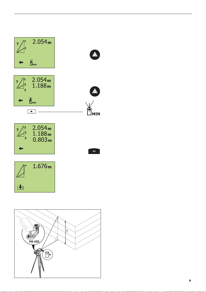
Three measurements are taken in sequence
from the fixed point A (preferably using a
tripod with the reference point set accordingly), whereby the second distance measured must be a “normal” distance (i.e. at right
angles to the distance to be determined).
The total distance is calculated by the PD 25.
Applications
- Determining a distance which cannot be
measured directly
- Measuring heights of buildings
2
3
Page 43

41
4. Working with the PD 25
Measuring distances indirectly , continued
Determining the total length of the side of a triangle, continued
The three measured values are shown in the display .
The result is shown in the display (i.e. the total distance calculated).
Calculate the total distance.
Continued
The display requests you to measure
the 3rd distance:
Take the measurement.
Measuring part of the length of the side of a triangle
Select the applicable symbol from the menu.
The display requests you to
measure the 1st distance:
Take the measurement.
A
A
Three measurements are taken in
sequence from the fixed point A (preferably
using a tripod equipped with the P A450 tripod adaptor), whereby the third distance
measured must be a “normal” distance
(i.e. at right angles to the distance to be
determined).
The distance is calculated by the PD 25.
Applications
- Determining the height of part of a facade
- Determining a distance which cannot be
measured directly
1
2
3
3 < 1!
3 < 2!
Page 44
42
Determining the length of the opposite side of a triangle according to the
Pythagoras principle
Two measurements are taken in succession
from the fixed point A (preferably using a tripod with the P A450 tripod adaptor), whereby the second distance measured must be
a “normal” distance (i.e. at right angles to
the distance to be determined).
The PD 25 calculates the distance to be
determined.
Applications
- Determining the heights of buildings
- Determining a distance which cannot be
measured directly
A
1
2
2 < 1!
4. Working with the PD 25
Measuring distances indirectly , continued
The display requests you to
measure the 2nd distance:
Take the measurement.
The display requests you to measure the 3rd distance (shortest
distance / at right angles to the distance to be determined):
Take the measurement.
or, alternatively:
Take the measurement in tracking mode
MIN in order to determine the right angle
(90°) exactly .
The three measured values are shown in the display .
The result is shown in the display (i.e. the length of part of the side
of the triangle).
Calculate the distance.
Measuring part of the length of the side of a triangle, continued
Continued
Page 45

43
Measuring distances indirectly , continued
4. Working with the PD 25
Measuring the length of the opposite side of a triangle according to the
Pythagorus principle, continued
The two measured values are shown in the display .
Calculate the distance.
Select the applicable symbol from the display . The display requests
you to measure the 1st distance:
The display requests you to measure the 2nd distance (at right
angles to the distance to be determined):
Take the measurement.
Take the measurement
or, alternatively:
Take the measurement in tracking mode
MIN in order to determine the right angle
(90°) exactly .
The result is shown in the display .
A
Notes concerning the button functions
Measured or calculated values can be saved by entering an intermediate memory location (0-9).
Measured or calculated values can be recalled by entering the
applicable intermediate memory location number (0-9).
Save
Recall
Scroll forward or back
Page 46

44
4. Working with the PD 25
The measurement is shown in the display .
Select the applicable symbol from the menu. The display then
requests you to take the
measurement:
Initiate tracking mode.
Move the tool slowly until the maximum measured value is shown in
the display .
Continuous measurement “tracking MAX”
With the “tracking MAX” function, the greatest or max. measured distance is always
shown in the display (e.g. for measuring a
diagonal).
The measured value indicated changes only
when the distance is increased.
Application
- Measuring the greatest distance between
two objects without having to target the
spot exactly .
Continued
Page 47

45
4. Working with the PD 25
The measurement is shown in the display .
Continuous measurement “tracking MIN”
Select the applicable symbol from the menu. The display then
requests you to take the measurement:
Initiate tracking mode.
With the “tracking MIN” function, the shortest or min. measured distance is always
shown in the display (e.g. for determining
the shortest distance).
The measured value indicated changes only
when the distance is decreased.
Applications
- Determining the shortest distance between two objects without having to target
the spot exactly .
- Determining a “normal” distance (at right
angles).
Move the tool slowly until the minimum measured value is shown in
the display .
Page 48

46
Select the corresponding symbol from the menu.
The display requests you to
measure the 1st distance:
Take the measurement.
4. Working with the PD 25
Measuring the mean value
After pressing the button only once,
8 measurements are taken consecutively.
Applications
- Measuring on uneven surfaces (plaster
etc.)
- Increasing accuracy
- Measuring equipment inspection
Select the corresponding symbol from the menu. The display then
requests you to take a measurement:
Initiate “mean value” measurement mode.
After the 8 measurements, the mean distance is displayed.
When the beep function is activated, the beep signal sounds each
time a measurement is taken.
Triangle calculations
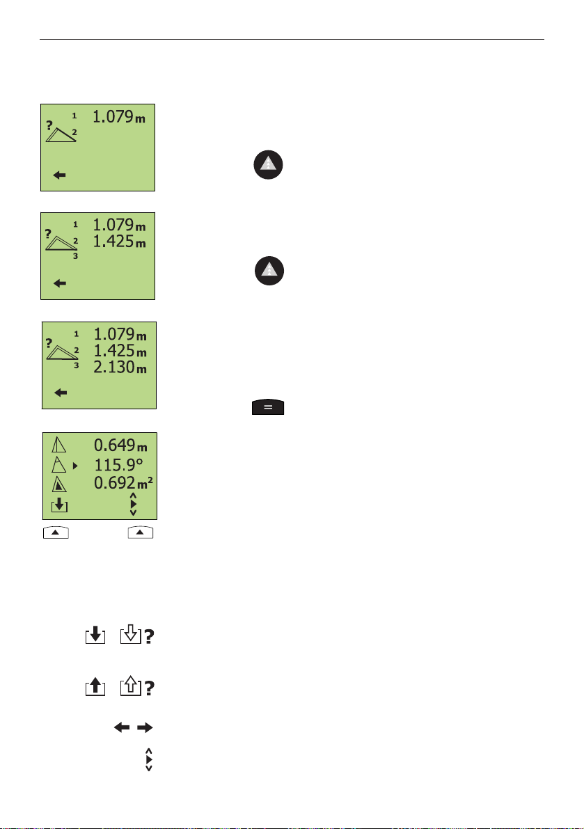
Determining the height, angle or area of a triangle
By measuring the lengths of the sides of a
triangle, the PD 25 can calculate:
- The angle between the first two measured sides
- The height and area of the triangle
Continued
Page 49
47
4. Working with the PD 25
Triangle calculations,continued
Determining the height, angle or area of a triangle, continued
The display requests you to
measure the 3rd distance:
Take the measurement.
The measured values for distances 1, 2 and 3 are shown
in the display .
Execute the calculation.
The display shows the:
- height
- angle
- area
of the triangle.
Select the desired value to be saved in intermediate memory .
The display requests you to
measure the 2nd distance:
Take the measurement.
Notes concerning the button functions
Save
Recall
Scroll forward or back
Scroll up or down
Measured or calculated values can be saved by entering an intermediate memory location (0-9).
Measured or calculated values can be recalled by entering the
applicable intermediate memory location number (0-9).
Page 50

48
Execute the calculation.
The display then shows:
- the length of the sloping section
- the angle of inclination
- the area of the gable end
of the pitched roof.
Triangle calculations,continued
Select the corresponding symbol from the menu.
The display requests you to
measure the 1st distance:
Pitched roof calculations
Take the measurement
Take the measurement
The display requests you to
measure the 2nd distance:
4. Working with the PD 25
The display requests you to
measure the 3rd distance:
Take the measurement
The measured values for distances 1, 2 and 3 are shown in the
display.
By measuring the height if the eaves, the
length of the base and the height of the
ridge, the tool is capable of calculating:
- The length of the sloping section
- The angle of inclination
- The area of the gable end
Applications
- Pitched roof calculations (gable end)
Select the desired value to be saved in intermediate memory .
Page 51

49
Setting out distances
4. Working with the PD 25
Adistance is divided into several individual distances.
The PD 25 can be used to measure the individual distances consecutively , i.e. set out the distances.
When the beep signal is activated, the frequency of the beeps
increases as the tool is moved closer to the point at which the
distance is to be marked.
Applications
- Setting out distances for drywall profiles
Select the corresponding symbol from the menu.
Enter the distance to be set out:
Use the numeric keypad to enter the following:
- Distance 1 (i.e. constant value for first
measurement)
- Distance 2 (i.e. individual, repetitive
distance)
...
Example 1: Fixed constant for 1st measurement
Move the tool slowly and set out (mark) the distances consecutively.
Move the PD 25 along the previously positioned profile until “0”
appears in the display .
Repeat the procedure until all distances to be set out have been
determined and marked.
Distances 1 and 2 can be measured, entered using the numeric
keypad or recalled from intermediate memory .
Page 52

50
Symbols shown in the display
Setting out distances, continued
4. Working with the PD 25
Increase distance
V alue displayed «-»
Distance to be set out has been reached.
Display indicates «0»
Decrease distance
V alue displayed «+»
Enter the distance to be set out
Use the numeric keypad:
- to set distance value 1 to “0”.
- distance value 2 to the desired value.
...
Example 2: Individual measurement repeated as many times as desired
Set out the distances as described previously .
Notes concerning the button functions
Save
Recall
Scroll forward or back
Scroll up or down
Measured or calculated values can be saved by entering an intermediate memory location (0-9).
Measured or calculated values can be recalled by entering the
applicable intermediate memory location number (0-9).
Page 53

51
Calculating the mean value from several measurements
4. Working with the PD 25
Select the corresponding symbol from the menu.
The display requests you to take the measurements.
Take the measurements consecutively
(max. 99).
The number of measurements taken and the corresponding mean
value are displayed continuously .
Saving the mean value or resetting the display
This function calculates the mean value from the measurements
taken (max. 99 consecutive measurements are possible).
Applications
- Continuous calculation of the mean value from several measurements.
The value displayed can be saved at a defi-
ned memory location (0....9) for use in furt-
her calculations or reset to “0” by pressing
the button.
...
Page 54

52
4. Working with the PD 25
Select the corresponding symbol from the menu.
2x
Shifting the measuring reference point to the rear
If desired, recall a predefined value from a
memory location (0...9), or
Use the numeric keypad to enter a value,
e.g. 1.500 m
Accept the value shown in the display .
Take the measurements.
The display shows the following
...
/
Shifting the measuring reference point
The measuring reference point used by the PD 25 can be shifted
forward or back by a manually entered or measured value. The set
value is then added or subtracted automatically to or from the rear
measuring reference point (standard) each time a measurement is
taken.
All measurements are then taken from this measuring reference point as long as the tool is used in this menu.
Applications
- Measuring from a relative reference point.
- Zeroing the tool in any position.
Continued
Page 55

53
Memory
Deleting memorised values
4. Working with the PD 25
Select the corresponding symbol from the menu.
Press button
to confirm.
All data is deleted
from memory .
Return to the special functions menu.
Shifting the measuring reference point, continued
Select the corresponding symbol from the menu.
Shifting the measuring reference point, continued
If desired, recall a predefined value from a
memory location (0...9), or
Use the numeric keypad to enter a value,
e.g. 1.500 m
Accept the value shown in the display .
Take the measurements.
ALL measurements saved in memory (max. 1000 memory
locations) are deleted.
...
Continued
/
/
The display shows the following:
2x
Page 56

54
Searching for, identifying or deleting measurements saved in memory
This function is used to recall or delete individual measurements
saved in memory (max. 1000 memory locations).
Measurements are identified by a max. 3-digit group and / or measurement code assigned by the user:
After selecting
the last memory location to which a value has been assigned is displayed.
Select
to scroll through memory and select, e.g.
Then press the
button to delete the measurement indicated from memory .
The value indicated is then deleted.
When deleted, a memory location is not available for further use
until all data has been deleted from memory .
Memory, continued
4. Working with the PD 25
Memory location
0-999
Measurement
Measurements can only be saved in memory (after each measurement is taken) when the memory function has been activated.
Please also refer to the section “3. Operation / setting preferences /
memory settings”.
Group code, e.g. for identification of the job
site (max. 3-digit number)
Measurement code
e.g. type of measurement (max. 3-digit
number)
Page 57

Connect (or disconnect) to/from the PD 25 for data communication.
Microsoft Excel®is started automatically when a connection has
been established successfully . Anew spreadsheet “table x” is opened in Excel®.
55
5. PD 25 server (option)
PD 25 server menu overview
5. PD 25 server (option)
The PD 25 server software permits the following:
- Transferring measurement data saved in memory to a PC
- Further processing of data in Microsoft Excel
®
When the PD 25 server software is installed, individual measurement or continuous measurement (tracking) can be carried out
directly from the PC.
- WIN95 / WIN98 / WIN NT 4.0 / WIN 2000 operating system
- RS232 interface (COM 1, 2, 3 or 4)
- Microsoft Excel
®
(version 5.0 or higher) for further processing of
data
PC requirements
Indication of
connection status
Connect
Download
Delete
Individual
remote
measurement
Downloads the measurement data from the PD 25 to the PC.
The measurement data is inserted in individual cells in the Microsoft
Excel
®
spreadsheet. Aconnection to the PD 25 is established when
this button is clicked.
Deletes all data from memory in the PD 25.
Takes an individual measurement.
The measurement is written directly into the Microsoft Excel
®
spreadsheet.
Dialog window
Log
Menus and
functions
Description of PD 25 server functions
Easy installation
using the installation
assistant
Remote
tracking
Initiates continuous measurement (tracking).
Measured values are written continuously into the Microsoft Excel
®
spreadsheet.
Continued
Page 58

56
5. PD 25 server (option)
Status indicators
Stop
Delete log
Stops the transmission of data from the PD 25 or the “tracking”
function.
Deletes all data from the log in the dialog window.
Measurement unit to
be used (m / in)
Connection with the PD 25 is active
Connection with the PD 25 is inactive
Unfavourable signal characteristics
Batteries almost exhausted
Record PD 25 data
transfer in the log in
the dialog window
(yes / no)
Preferences
Interface used
Data transfer rate
Info
Exit
Opens the preferences dialog window (settings).
The following settings can be made as long as no connection to the
PD 25 has been established:
- Baud rate
- Interface used (COM 1...4)
Opens the info dialog window showing the
PD 25 server software version number
Exit from PD 25 server software
Description of PD 25 server functions, continued
Page 59

57
5. PD 25 server (option)
Installing and setting up the PD 25 server software
1 Insert the 3 1/2” diskette in the floppy
drive and double-click with the mouse on
the symbol for the floppy drive.
2 Double-click the file “Setup.exe” to start
the installation.
3 Follow the instructions displayed on the
screen by the installation assistant.
End the installation
after entering your name and
name of company ,
target folder and programme
group.
Standard installation
Always click on “continue” in the installation assistant to install the PD 25 server
software with the standard settings or
when you are unsure of the installation
procedure.
4 When the installation has been succes-
sfully completed:
Start the server software from the programme group “Hilti PD 25”.
Amenu appears on the screen.
5 Click the symbol.
The preferences window (PD 25 server
settings) appears on the screen.
6 Check or alter the settings and confirm
the information by clicking “OK”.
Important:Activate the correct interface
(COM 1...4) to which the PD 25 is
connected for data transfer to your PC.
7 See “Connecting the PD 25 to a PC”.
Quick-start instructions (MS Word)
1
2
Installation assistent
PD 25 server dialog window
Einstellungen durchführen
Hilti PD 25 server setup is preparing the
Installshield®Assistant which will guide you
through the setup procedure. Please wait.
Page 60

58
5. PD 25 server (option)
Connecting the PD 25 to a PC
RS232
EIN
COM1 ... 4
1. Use the Hilti interface cable to connect
the PD 25 to the PC.
Tighten the screw on the PD 25
connector.
2. Switch on the PD 25.
3. Switch on the PC and the start the PD 25
server software.
4. The data transfer rate must be set to the
same baud rate in the settings menu on
the PD 25 and in the preferences window
of the PD 25 server software.
5. The other settings (COM 1...4 / metres,
inches / display data) in the PD 25 server
preferences window should be checked
and adapted if necessary .
7
C
9
8
4
5
6
1
0
2
3
.
=
l
max.
= 10m
Continued
4
1
2
3
ON
Page 61

59
5. PD 25 server (option)
The PD 25 server software in use, continued
Other functions
The PD 25 server software in use
- The PD 25 is connected to the PC
- The PD 25 and the PC are switched on
- The PD 25 server software is installed on the PC
The correct settings have been made in the “preferences” menu.
2. Click the symbol.
The connection from the PC to the PD 25 is activated.
3. Click the symbol. Measurement data is transferred from
the PD 25 and written directly in individual, consecutive lines in
Microsoft Excel.
®
4. The measurement data is then available for further processing by
the user in Microsoft Excel®.
1. Start the PD 25 server software.
The PD 25 server dialog window and Microsoft Excel®are
opened automatically .
Before beginning,
check that
Procedure
PD 25 Server MS Excel
®
Date, time (end of transfer)
Memory location number
Group code
Measurement
code
Measurement
Unit in decimal form (m / in)
Remoter
individual
measurement
Takes an individual measurement.
The measurement is written directly into Microsoft Excel
®
.
Remote
tracking
Begins continuous measurement (tracking).
Measurements are written continuously into Microsoft Excel
®
.
Stop
Stops the transmission of data from the PD 25 or the “continuous
measurement” function.
Page 62

60
Uninstalling the PD 25 server software
PD 25 server software troubleshooting
Select Preferences / Control Panel / Software / Install / Uninstall. Mark PD 25 server software and click on Add / Remove.
The PD 25 server software will then be removed from your PC.
5. PD 25 server (option)
The PD 25 server software in use, continued
Unfavourable conditions affecting the signal
Batteries almost exhausted
No connection to the PD 25
- Observe the minimum measuring distance (>300 mm).
- Clean the lens.
- Take the measurement from
a different surface (use the
P A411 target plate).
- Shield the target spot from
bright sunlight.
- Insert new batteries.
- Set the baud rate for the PD
25 (tool) and PD 25 server
software (PD 25 server preferences) to the same value
(must be identical).
- Check the plug connections.
Display Fault Remedy
Page 63

61
6. Care, transportation and storage
6. Care, transportation and storage
Cleaning and drying
• Blow dust off the lenses.
• Do not touch the glass with your fingers.
• Use only clean, soft cloths for cleaning. If necessary , moisten
slightly with pure alcohol or water.
Do not use any other liquids as these may damage the plastic components.
Observe the temperature limits when storing your equipment. This
is particularly important in summer if the equipment is kept inside a
motor vehicle (storage temperatures: -30°C to +70°C / -22°F to
+158°F)
Storage
Remove the tool from its case if it has become wet. The tool, its
carrying case, foam insert and accessories should be cleaned and
dried.
Put the equipment back into its case only when it is completely dry .
Check the accuracy of the equipment before it is used after a long
period of storage or transportation.
Transportation
Y our equipment should be shipped in the Hilti toolbox.
Always remove the batteries before shipping.
Page 64

62
7. Symbols displayed
T emperature too high
(> +50°C), in tracking mode and
in setting-out mode
(> +45°C)
T emperature too low
(< -10°C)
Unfavourable reception
conditions
General hardware fault
Batteries almost exhausted
Ambient light at target too
bright
Allow the tool to cool.
Warm the tool.
Observe the min. measuring
distance (> 300mm).
- Clean the lens.
- Take the measurement from
a different surface (target
plate).
- Shade the target point from
background light.
Switch the tool off and on
again. If the fault persists,
please contact a service
centre.
Insert new batteries.
Shade the target point from
bright light.
7. Symbols displayed
Symbol Information / fault Remedy
Page 65

63
8. Measuring equipment inspection
8. Measuring equipment inspection
Measuring equipment inspection of the PD 25 for users certified
according to ISO 900...
Y ou may carry out the measuring equipment inspection required by
ISO 900... on the PD 25 linear measuring device yourself (see DIN
18723-6; Procedures for checking the accuracy of geodetic instru-
ments in the field: Part-6, opto-electronic range meters for short
distances).
To do this, select a measuring distance which remains constant over
a period of time and which is easily accessible. It should have a
known length of approx. 1 to 5 m (e.g. a window opening or the
width of a room) and 10 measurements should be made.
Determine the deviation of the readings from the nominal measuring
distance and calculate the standard deviation on this basis.
Make a note of this value and the date or time for the next inspection.
Repeat these verification measurements at regular intervals as well
as before and after important measuring tasks.
Apply a measuring equipment inspection sticker to the PD 25 and
document the entire inspection procedure.
Y our PD 25 conforms to the specified accuracy if the standard
deviation remains less than or equal to 3mm.
APD 25 which has been tested / inspected over the test distance
will operate with the accuracy specified in the operating instructions
over the entire specified length and temperature range. Please refer
to the technical data contained in the operating instructions and to
the explanation of the accuracy values.
Recommendation
Test the tool, or have it tested, once a year. Contact your Hilti representative for further information. The tool can also be tested at one
of our repair / service centres where confirmation of inspection can
be given and, when necessary , a certificate issued for your documentation.
Page 66

64
9. Accessories
9. Accessories
P A411 target plate
With two different target surfaces
- White, for use when reflection is excessive
- Brown, when reflection is too low
P A970 sighting glasses
The sighting glasses improve visibility of the laser target spot (by
the factor 4-5).
P A440 data set for the PD 25
- RS232 serial interface cable for connecting the PD 25 to a PC
(for data transfer)
- 31/2” diskette containing the PD 25 server software
P A450 tripod adaptor
With fine adjustment of the X- and Y-axis for working accurately
from a tripod.
(The measuring reference point must be set to .)
Continued
Page 67

65
P A421 telescopic sight
Used to position the target spot exactly on objects from which measurements are taken.
9. Accessories
9. Accessories, continued
Do not aim the P A421 telescopic sight at objects with highly
reflective surfaces.
Page 68

66
10. FCC statement (applicable in US)
10. FCC statement (applicable in US)
WARNING
This equipment has been tested and found to comply with the limits
for a Class II digital device, pursuant to part 15 of the FCC Rules.
These limits are designed to provide reasonable protection against
harmful interference in a residential installation. This equipment
generates, uses and can radiate radio frequency energy and, if not
installed and used in accordance with the instructions, may cause
harmful interference to radio communications. However, there is no
guarantee that interference will not occur in a particular installation.
If this equipment does cause harmful interference to radio or television reception, which can be determined by turning the equipment
off and on, the user is encouraged to try to correct the interference
by one or more of the following measures:
• Reorient or relocate the receiving antenna.
• Increase the separation between the equipment and receiver.
• Connect the equipment into an outlet on a circuit different from
that to which the receiver is connected.
• Consult the dealer or an experienced radio/TV technician for
help.
11. EC declaration of conformity
Designation: PD 25
Serial number: 00000001 - 50000000
Y ear of design: 2000
-konform
We declare, on our sole responsibility , that this product complies
with the following standards or standardisation documents:
EC directive 89/336/EWG and the applicable standards DIN EN
50081-1 (03.93), DIN EN 50082-2 (03.95), certificate no. 010b/00-d
issued by the departement responsible.
Hilti Corporation
Armin Spiegel
Leiter Positioning Systems
Head of Business Unit
Bodo Baur
Leiter Qualität Positioning
Systems
Quality Manager of Business Unit
Positioning Systems 04/2000
Page 69

67
12. Warranty
12. Warranty
Hilti warrants that the tool supplied is free of defects in material and
workmanship. This warranty is valid so long as the tool is operated
and handled correctly , cleaned and serviced properly and in accordance with the Hilti operating instructions, all warranty claims are made
within 12 months from the date of the sale (invoice date), and the technical system is maintained. This means that only original Hilti consumables, components and spare parts may be used in the tool. This
warranty provides the free-of-charge repair or replacement of defective parts only . Parts requiring repair or replacement as a result of normal wear and tear are not covered by this warranty .
Additional claims are excluded, unless stringent national rules
prohibit such exclusion. In particular, Hilti is not obligated for
direct, indirect, incidental or consequential damages, losses or
expenses in connection with, or by reason of, the use of, or inability to use the tool for any purpose. Implied warranties of merchantability or fitness for a particular purpose are specifically
excluded.
For repair or replacement, send the tool and/or related parts immediately upon discovery of the defect to the address of the local Hilti
marketing organisation provided.
This constitutes Hilti’s entire obligation wiht regard to warranty and
supersedes all prior or contemporaneous comments and oral or written agreements concering warranties.
Page 70

Hilti Corporation Headquarters
FL-9494 Schaan
Tel.:+423/ 236 2111
Fax: +423 / 2362965
www.hilti.com
Hilti = reg. trademark of Hilti Corp., Schaan W2402 0500 1 englisch 9 Printed in Liechtenstein © 2000
Right of technical and programme changes reserved S.E.&O.
334080
 Loading...