

Hilti D-LP 32, DS-TS 32 Operating Instructions Manual
Operating instructions en
D-LP 32/
DS-T S 32
Printed: 08.07.2013 | Doc-Nr: PUB / 5069667 / 000 / 01
2
D-LP32/DS-TS32
Hydraulic unit
Remote control unit
Rail
Saw blade
Blade guard
Hydraulic hoses
End stop
Rail support
Printed: 08.07.2013 | Doc-Nr: PUB / 5069667 / 000 / 01

3
Contents
1. General information 4
2. Description 5
3. System components, tools and accessories 13
4. Technical data 17
5. Safety precautions 21
6. Before use 27
7. Operation 35
8. Care and maintenance 43
9. Troubleshooting 45
10. Disposal 50
11. Manufacturer's warranty – tools 51
12. EU declaration of conformity (original) 52
Printed: 08.07.2013 | Doc-Nr: PUB / 5069667 / 000 / 01
4
1. General information
It is essential that the operating instructions are read
before the equipment is operated for the first time.
Always keep these operating instructions together
with the equipment.
Ensure that the operating instructions are with the
equipment when it is given to other persons.
Safety notices and their meaning
1.1
DANGER
Draws attention to imminent danger that will lead to
serious bodily injury or fatality.
WARNING
Draws attention to a potentially dangerous situation that
could lead to serious personal injury or fatality.
CAUTION
Draws attention to a potentially dangerous situation that
could lead to slight personal injury or damage to the
equipment or other property.
NOTE
Draws attention to an instruction or other useful information.
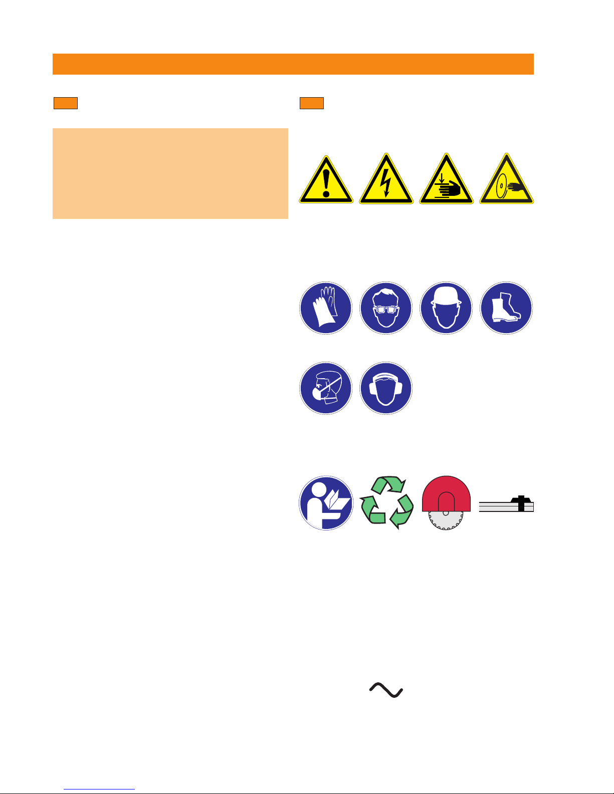
Explanation of the pictograms and
other information
1.2
General warning Warning:
electricity
Warning:
avoid hand injuries
Warning signs
Obligation signs
Warning:
Risk of cutting
injury
Wear protective
gloves.
Wear safety
footwear.
Wear respiratory
protection.
Wear eye
protection.
Wear a hard hat.
Wear ear
protection.
Symbols
Return waste
material for recy-
cling Return waste
material for
recycling
Always fit the blade
guard
Always fit the rail
end stops
Read the operating
instructions before
use
A
Amps
V
Volts
kW
Kilowatts
Hz
Hertz
mm
Millimeters
/min
Revolutions
per minute
l/min
Liters per minute
rpm
Revolutions
per minute
bar
Bar
ii
Alternating current
Printed: 08.07.2013 | Doc-Nr: PUB / 5069667 / 000 / 01

5
2. Description
Description 2.1 Areas of application 6
2.2 D-LP32/DS-TS32 hydraulic saw system components 6
2.3 Parts and operating controls 8
Printed: 08.07.2013 | Doc-Nr: PUB / 5069667 / 000 / 01

6
2. Description
Areas of application
TheD-LP 32/DS-TS32 is a medium to heavy-duty, high-
performance wall saw system for use with saw blades
of up to 1600 mm dia. It is capable of cutting to a depth
of 73 cm.
The D-LP 32 hydraulic unit has a nominal power of
32 kW at 63 amps but can also be operated on 32 amp
mains supplies.
Its modular design permits rapid assembly and use for
many different applications. The DS-TS32 saw head, for
example,can be used to power the Hilti DS-WSS 30 high-
performance wire saw system.
Using the D-RC-LP32digital remotecontrol unit to adjust
the infinitely variable oil flow rate, the operator canselect
the optimum speed and most suitable rate of advance.
This feature ensures optimum efficiency for wall sawing, hydraulic coring, plunge sawing or wire sawing.
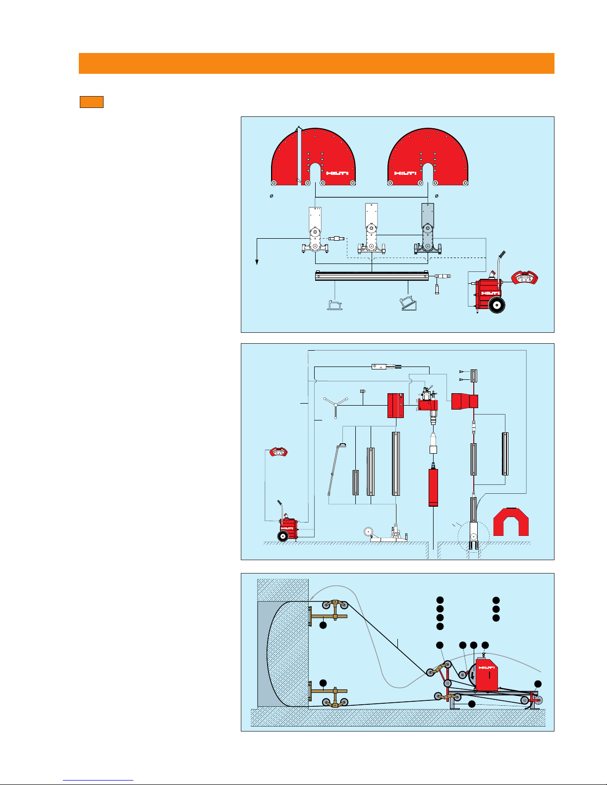
2.1
D-LP32 /DS-TS32 hydraulic saw
system components
The basic diamond saw system consists of the following components:
D-LP32 hydraulic unit
D-RC-LP32 remote control unit
DS-TS 32 saw head
D-R 200L rail
DS-C...H saw blade
DS-BG blade guard
D-PH/FH hydraulic hoses and water supply hose
DS-ES-L end stop (2 end stops supplied with each
D-R..L rail)
D-LP32/ DS-TS 32 tool set
2.2
9
1
2
7
3
5
4
6
8
Printed: 08.07.2013 | Doc-Nr: PUB / 5069667 / 000 / 01
7
2. Description
D
-LP
3
2
D
-R 50-230L
DS-TS 32
DS-RF DS-RFP
D-EP-ML
DS-TS 22
D-CO-ML
D
S-ES-L
DS-BG
800 - 1600
mm
DS-BGF
800 - 1600
mm
D-FH14/14-10
D
-LP15
D-PH58-10 (2x)
D-PH34-10 (2x)
D-FH4/14-10
3/4" - 5/8"
(2x)
D-RC-LP 32
DS-TS 30
D
S-ES-L
D-LP32/DS-TS 32
Wall saws
2x DS-WS-SPP
7
DS-WSWS
6
2x DS-WSRF
5
DS-WSRP
4
DS-WSWD
3
DS-WSTA
2
DS-WSW500
1
DS-W11
7
6
5
7
4
123
D-LP 32/DD-750 HY/DS-PS 30
Hydraulic core drilling rig
Plunge saw
D-LP32/DS-TS32/DS-WSS 30
Wire saw
D-LP32/DS-TS, PS, WSS and DD modular system
2.2.1
D-R 150-L
D-S 150
D-R 200-L
DD-BA 6/DD-BA 3-70
DD-AF-HY
D-RC-LP 32
DD-CA-L
DD-MF-ML
DD-750HY
DD-BU-202
DD-R 100-M
DD-R 40-M
D-CO-ML
DS-CA-L/M
DD-R 130-M
DS-PS30
D-LP32
DD-FH
DS-B
O
600 - 1200
D
S-BG 12-PS
PH
FH
D-R 100-L
Printed: 08.07.2013 | Doc-Nr: PUB / 5069667 / 000 / 01
8
2. Description
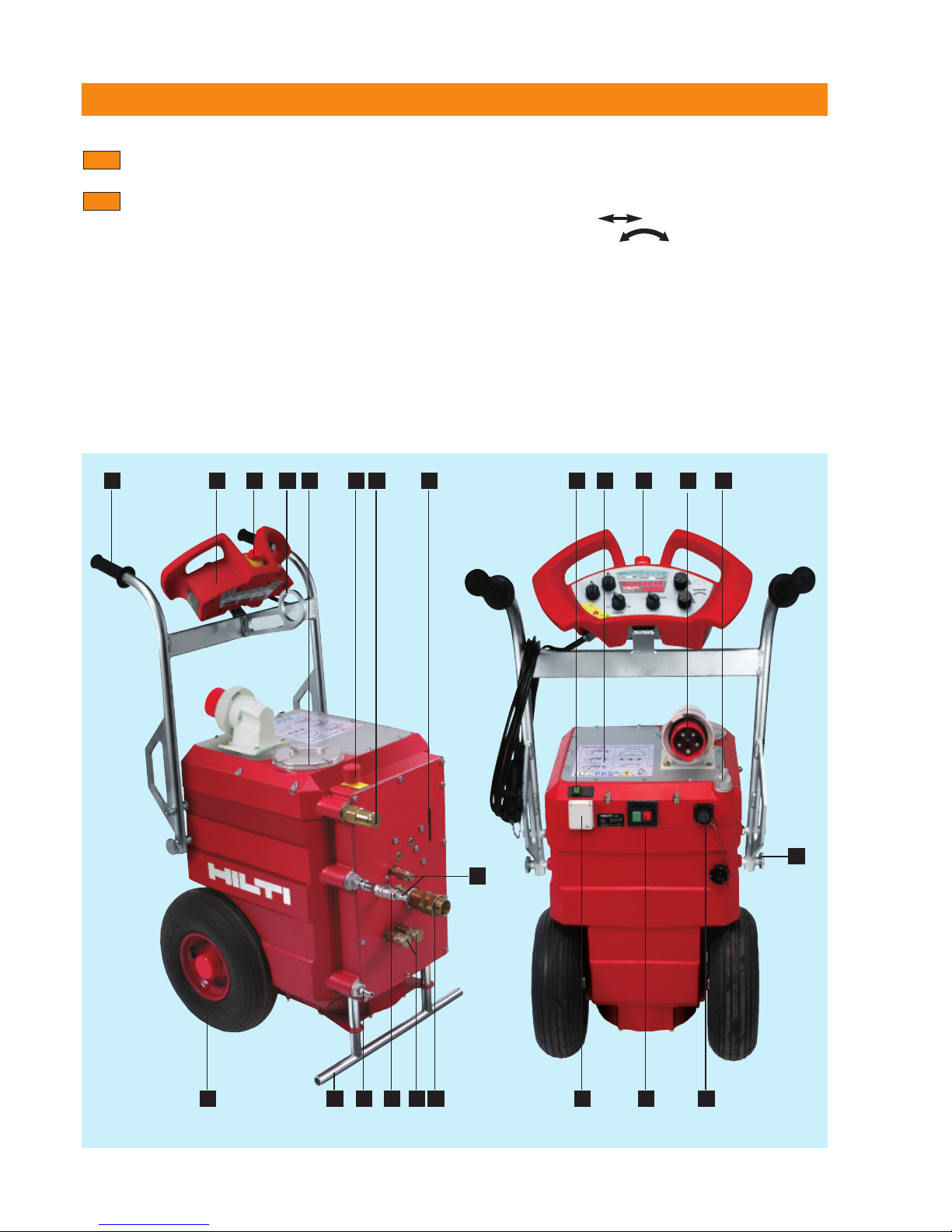
Parts and operating controls
D-LP32 hydraulic unit
Transport handle, hinged
Lifting point for transport by crane
400 V 63 A socket, mains supply (Euro standard
socket as per EN CEE63)
230 V socket
Socket for D-RC-LP32 remote control unit
Oil level sight glass
Oil filter cover
Emergency off switch
Guidelines for use (sticker)
2.3
2.3.1
Wheels with puncture-proof tyres
PH
3
/4˝ coupling for pressure hose
PH3/4˝ coupling for return hose
FH1/4˝ couplings for advance control hoses
FH1/4˝ couplings for saw arm
Coupling for water supply from the site
Water supply to saw head (with water flow rate reg-
ulation)
D-RC-LP32 remote control unit
On / off control switch
Cap / oil filler neck
230 V socket overload reset button
Front support
Hinged transport handle locking mechanism
28171 7 68 12
10 1521 16 14 11
13
9 820
3
19
184 5
22
Printed: 08.07.2013 | Doc-Nr: PUB / 5069667 / 000 / 01

9
2. Description
Guidelines for use (sticker on D-LP32 hydraulic unit)
2
.3.2
®
Guideline • Richtlinie • Guide
D-LP 32 /DS-TS 32
356749
D-LP 32 /DS-TS 32 /WSS 30
45-50 Ampere
100 l/min
D-LP 32 /DD 750-HY
32-45 Ampere
40–60 l/min
32-63 Ampere
80–100 l/min
D-RC-LP 32
Start
Ampere
II
I
3
263
45
1
0
0
1600
1
2
0
0
1
0
0
0
9
0
0
8
0
0
m
m
D-RC-LP 32
Start
Ampere
II
I
32 63
45
1
0
0
1600
1200
1000
9
0
0
8
0
0
m
m
220
k
g
D-RC-LP 32
Start
Ampere
II
I
32 63
4
5
1
0
0
1
6
0
0
1
2
0
0
1
0
0
0
9
0
0
8
0
0
m
m
6
0
4
0
8
0
6
0
4
0
80
6
0
4
0
80
Printed: 08.07.2013 | Doc-Nr: PUB / 5069667 / 000 / 01
10
2. Description
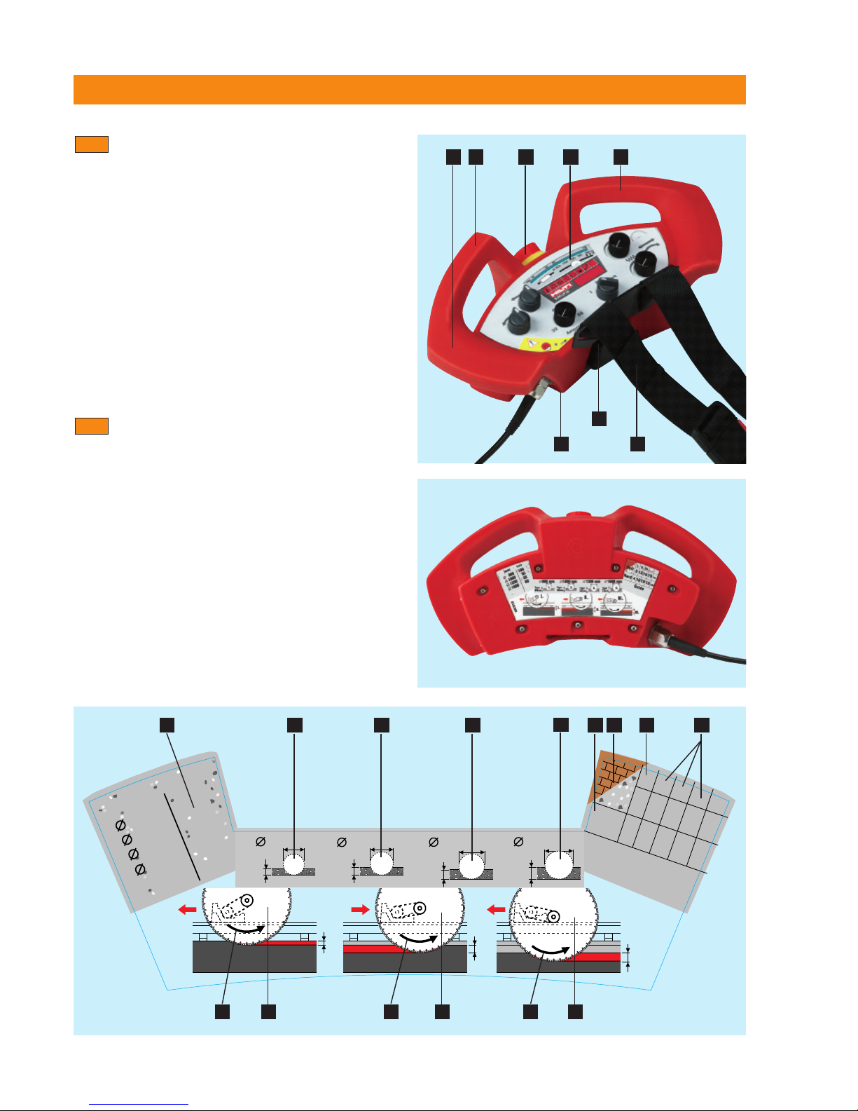
D-RC-LP32 remote control
Remote control unit casing
Grips / control panel protection bars
Display and operating controls
Attachment point for belt fastener
Shoulder belt with fastener
Rear side of remote control unit: Sawing guidelines
Emergency OFF switch
2
.3.3
Sawing guidelines
See sticker on the rear of the D-RC-LP32 remote con-
trol unit.
Cutting depth for soft concrete / masonry
Cutting depth for hard concrete
Optimum blade diameter sequence
Plunge depth for initial guide cut
Plunge depth for subsequent cuts
Cut no. I - saw arm trailing
Cut no. II - saw arm leading
Cut no. III - saw arm trailing
Direction of blade rotation (counterclockwise, as
seen from side where blade is fitted)
Recommended oil flow rate in l/min. (speed) for
corresponding blade dia. (mm)
2.3.4
1 2 7
4
56
3 2
l.
ll.
lll.
lll.
ll.
l.
15
15
15
l.
ll.
lll.
....
cm
Hard
Guide
cm
T
max
33cm
800 mm
1.
T
max
43cm
1000 mm
2.
T
max
53cm
1200 mm
3.
T
max
73cm
1600 mm
356751/8
4.
800
100
1000
95
1200
85
1600
80
(mm)
l/m
i
n
Soft
5
4
10
10
10
310 3 5413
3
2
69 7 89 9
Printed: 08.07.2013 | Doc-Nr: PUB / 5069667 / 000 / 01
D-RC-LP 32
Start
Ampere
II
I
32 63
45
1
0
0
1
6
0
0
1
2
0
0
1
0
0
0
900
8
0
0
mm
8
0
6
0
4
0
11
2. Description
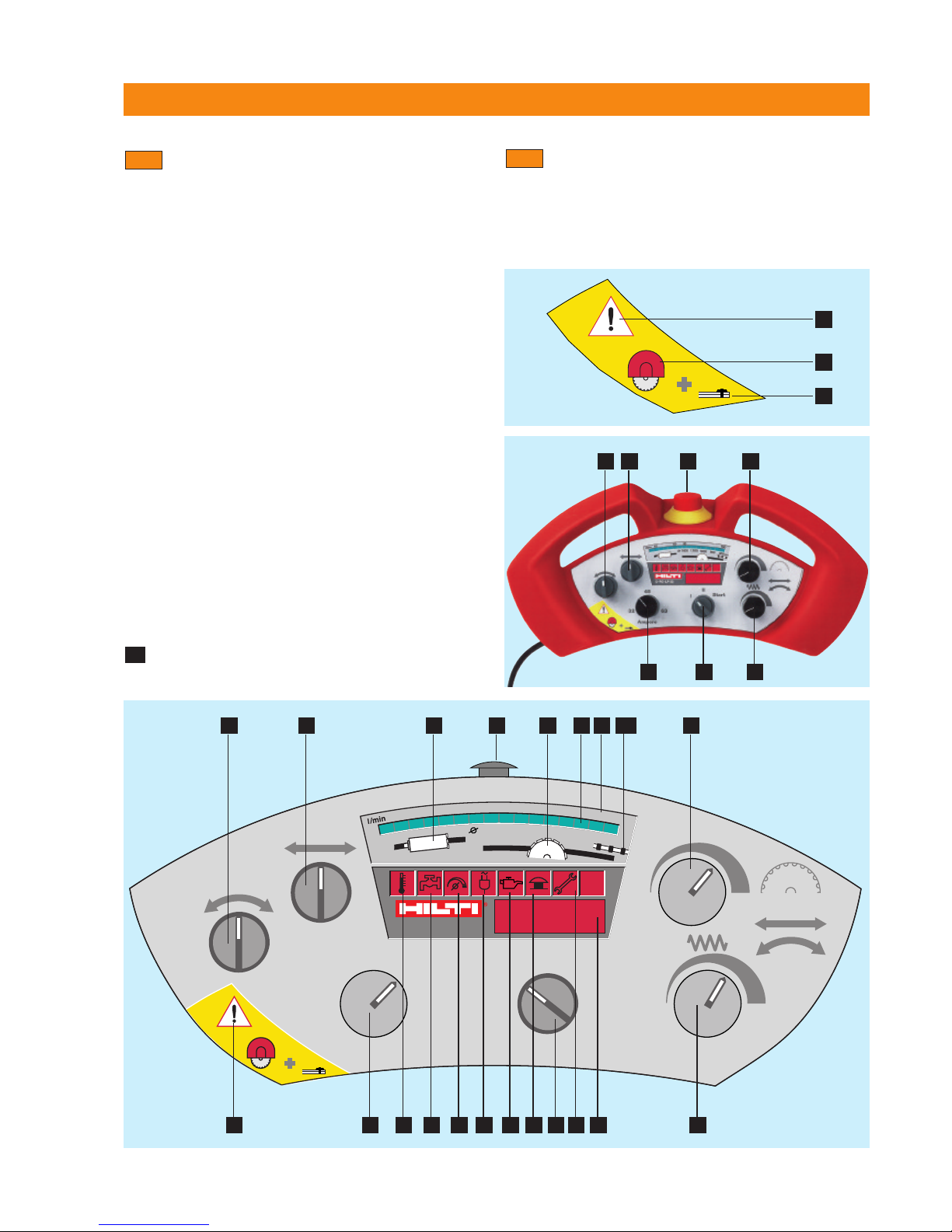
Display, symbols and warning lamps on the
D-RC-LP 32
Hydraulic unit starting switch (OFF/ON/Start)
Oil flow rate (blade drive speed) 30–100 l/min.
(green spot lights up)
Direction of blade plunge movement (right / left)
Direction of advance (left / right or up / down)
Speed control for and
Power control (amps), depending on mains supply
Emergency OFF switch
Oil flow rate indicator
Position of green spot corresponding to saw blade
diameter
Temperature indicator, lights briefly before cut-out
on overheating
Water cooling: lights when unit is inadequately cooled
Zero position: lights when one of the control knobs
is not in the "zero" or "neutral" position
Mains supply / warning lamp
Oil level: lights when oil level is too low
Emergency OFF: lights when button is pressed in
Service indicator: lights when service is due
Operating hours indicator / working pressure (bar)
Operating range for sawing
Operating range for wire sawing
Operating range for core drilling
2
.3.5
18A
Warnings
Warnings
General warning
Always fit the blade guard
Always fit the rail end stops
2.3.6
3 4 19 7 18 9 8 2
21
22
23
20 6 10 11 12 13 14 15 1 16 17 5
3 4 7
6 1 5
2
18A
Printed: 08.07.2013 | Doc-Nr: PUB / 5069667 / 000 / 01
12
2. Description
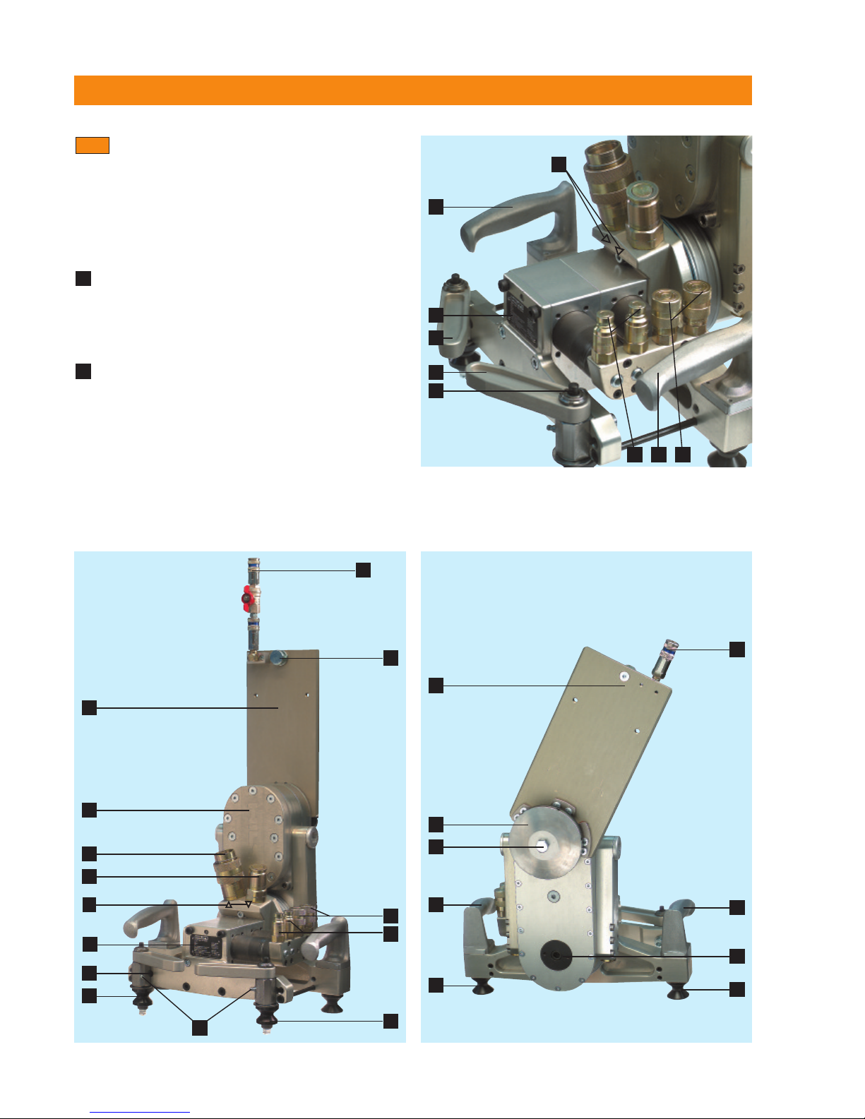
DS-TS32 saw head
Saw arm with built-in motor
Blade guard holder (moves with the saw arm)
Carriagewithwear-resistantcam-action steelrollers
Cam-action roller locking lever
Hydraulic coupling (PH
3
/4˝) – pressure hose
Direction of oil flow
Hydraulic coupling (PH
3
/4˝) – return hose
Hydraulic couplings (FH
1
/4˝) – advance
Hydraulic couplings (FH
1
/4˝) – saw arm pivot
Water supply
Water control valve: may be fitted at blade guard or
at hydraulic unit
Sawblademountingflange with specialM12×25 / 10.9
grade steel screw
Grips
Cam-action rollers
Clamping screw for positioning blade guard holder
and blade guards
Cam-action roller lockbutton
2.3.7
5
A
9A
11 87
17
9A
9
11
13
12
8
7
12
11
15
4
4
14
2
1
6
5
5A
15
3
12
16
2
10
18
11
12
Rating plate
Grease nipple for cam-action roller bearing
Holder for blade guard rubber
Special M12×25 / 10.9 screw
5
A
Printed: 08.07.2013 | Doc-Nr: PUB / 5069667 / 000 / 01

13
3. System components, tools and accessories
System components, 3.1 Hydraulic hoses and hydraulic hose set 14
tools and accessories 3.2 D-R..L rails, DS-ES-L end stops, DS-RF rail supports
and DS-RFP angular cutting plate 14
3.3 DS-BG / BGF blade guard 14
3.4 DS-FCA-110 flush-cutting flange 15
3.5 Diamond saw blades 15
3.6 Accessories, D-LP32/DS-TS32 tool set 16
Printed: 08.07.2013 | Doc-Nr: PUB / 5069667 / 000 / 01

14
3. System components, tools and accessories
Hydraulic hoses and hydraulic hose set
3.1
DS-PH34-10 DS-FH4/14-10
hydraulic hose set hydraulic hose set (with water supply hose)
D-R50L rail
D-R100L rail
D-R150L rail
D-R200L rail
D-R230L rail
DS-ES-L end stop
D-R..L rails, DS-ES-L end stop, DS-RF rail support and
DS-RFP angular cutting plate
3.2
Accessories for securing and operating the saw
DS-BG / BGF blade guard
3.3
DS-ES-L DS-RFPDS-RF
Item no. Designation Use
238000 DS-BG65 blade guard Bladeguard for blades up to650 mm dia.
238002 DS-BG80 center section Blade guard for 600 to 900mm dia. saw blades *
238003 DS-BG80 side section Bladeguard for 600 to 900 mmdia. saw blades
238004 DS-BG120 center section Bladeguard for 1000 to 1200 mm dia. saw blades *
238005 DS-BG120 side section Bladeguard for 1000 to 1200 mm dia. saw blades
333883 DS-BG16 blade guard Bladeguard for 1200 to 1600 mm dia. saw blades
Item no. Designation Use
238006 DS-BGF80 center section Bladeguard for 600 to 900 mmdia. saw blades for flush cutting *
238007 DS-BGF80 side section Bladeguard for 600 to 900 mmdia. saw blades for flush cutting
238008 DS-BGF120 center section Bladeguard for 1000 to 1200 mm dia. saw blades for flush cutting *
238009 DS-BGF120 side section Blade guard for 1000 to 1200 mm dia. saw blades for flush cutting
256237 DS-BGF16 blade guard Blade guard for 1200 to 1600 mm dia. saw bladesfor flush cutting
* Only to be used with the corresponding side sections!
DS-BG DS-BGF
D-R..L
Printed: 08.07.2013 | Doc-Nr: PUB / 5069667 / 000 / 01
15
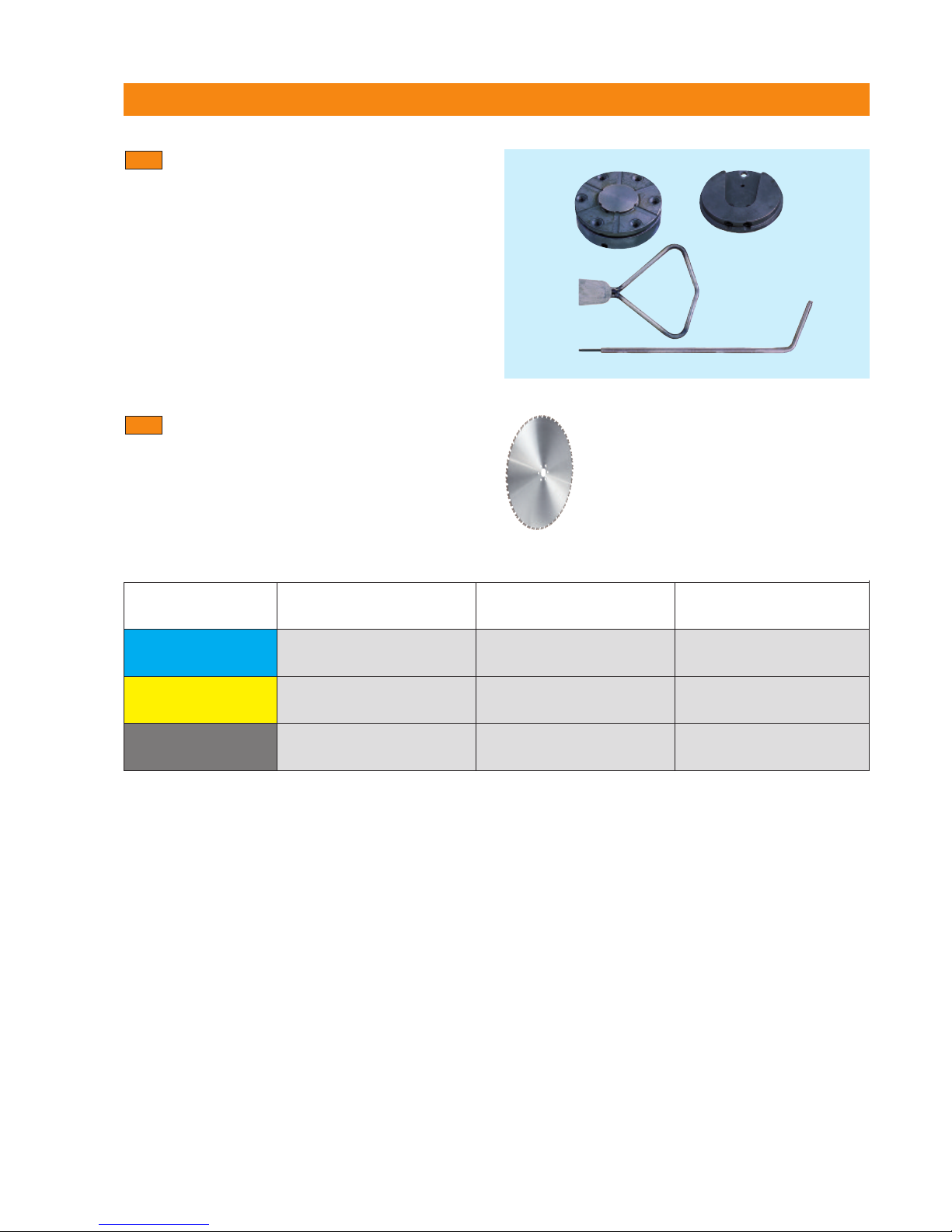
3. System components, tools and accessories
Recommendations for use: Which specification for which material?
Diamond saw blades
We recommend Hilti CS-H, CM-H or CH-H saw blades
for use with the D-LP32/DS-TS32. The saw blades can
be selected from the following table, taking material,
steel content and dimensions into account.
3.5
Important
■ Sawing at a lower speed (reduced saw blade r.p.m.) is usually advantageous when difficult conditions such as
high steel content or hard aggregates etc. are encountered.
■ Safety precaution: Keep to the recommended settings in order to ensure that blade peripheral speed remains
within the safe range for the saw blade used.
DS-FCA-110 flush-cutting flange
3.4
Specification Cutting characteristics Type of concrete Reinforcement
CS-H / UP Fast-cutting Soft aggregates Normal to high
CM-H / UP Well-balanced, good speed and life Hard aggregates Normal
CH-H / SP Fast-cutting and long life Soft to very hard aggregates Normal to high
Printed: 08.07.2013 | Doc-Nr: PUB / 5069667 / 000 / 01
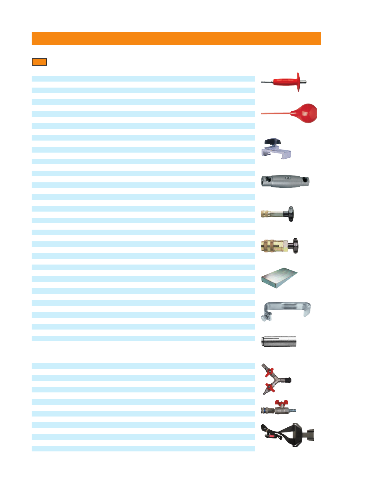
3. System components, tools and accessories
D-LP32 / DS-TS32 tool set
3.6
16
O
rdering designation Qty. Use
D-LP32/DS-TS32 tool set 1 LP 32/TS32 hydr. saw system
comprising:
Hilti plastictoolbox with insert 1 Operator
Accessories,listofcontents and theiruse 1 Operator
F
olding rule, 2 m 1 Operator
STOFcleaningcloth 1 Operator
Flatbrush 1 Operator
Hilti spray 1 Operator
Hilti grease dispenser 1 Operator
Ear protectors 1 Operator
S
afety goggles 1 Operator
HSD-G M12 settingtool 1
Setting anchors
BB blow out pump 1
Anchor holes
Spirit level 1 Assemblingrails
Open-end/ ring wrench,19 mm 1 Assemblingrails
Open-end/ ring wrench,18 mm 1 Assemblingrails
Screwdriver 1 Assembly
Hammer 1
1
/2kg 1 Setting anchors
Socket, 19 mm AF 1 Assemblingrails
Extension,
1
/2˝ square drive 1 Assembling rails
Ratchet,1/2˝ square drive 1 Assemblingrails
D lever with
1
/2˝ square drive 1 Assemblingrails
D-CP-ML rail clamp 1
Mountingrails
Hex.screw,M12×40/8.8 8 Fastening rail support
Hex.screw,M12×70/8.8 8 Fastening rail support
Washer 8 Fastening rail support
Clampingpiece 1 Sparepartrailsupport
Washer,12×18×1 3 Spare part rail support
Spring, 1×12×25 3 Spare part rail support
M12nut with collar 8 Angular cutting plate
D-EP-ML1/2˝ eccentric pin 3 Rail extension
D-CO-ML taper 1
Railextension
Rubber 2 Blade guard holder
Gripnut 1 Fastening blade guard
Hex.key, 4 mm 2 Eccentric rollers / covers
Hex.key, 10 mm 1 Fastening blade guard holder
DS hex. key with T-grip 1 Eccentric rollers
D-PRT pressure releasevalve FH
1
/4˝ 1
Pressurerelease FH1/4˝
D-PRT pressure releasevalve PH3/4˝ 1
Pressurerelease PH3/4˝
D-steel wedge130×70×20 6
Securingconcreteblock
Copper ring 5 Core bit extension
Special M10 countersunk-head srew (6 screws) 1 Spare part,DS-FCA flange
Set of 3 seals 1 Spare part, DS-FCA flange
Special hex. screw, M12×25/10.9 2 Spare part,mountingsaw blade
Hosecoupling, 15–24 mm 2 Attaching water hose
Additional accessoriesfor the D-LP32/DS-TS32 (not includedin the toolset)
Ordering designation Qty. Use
DS-ES-L end stop 2
SecuringcarriageL
HKD-D M12×50 flushanchor 50
16 mm dia. hole
Water valve Y-piece 1
Water supply
Water valve 1
Water supply
Water connector for saw head 1 Spare part for saw head
Hydraulic coupling, FH
1
/4˝ (female) 1 Spare part for FH1/4˝
Hydraulic coupling, FH1/4˝ (male) 1 Sparepartfor FH1/4˝
Hydraulic coupling, PH
3
/4˝ (female) 1 Sparepartfor PH3/4˝
Hydraulic coupling, PH3/4˝ (male) 1 Spare part for PH3/4˝
HVLP46 hydraulic oil (25 litres) 1 Hydraulic unit
Sharpening plate,319 × 319× 18 mm 1 Sawblades, core bids
D-RC-Ext10 extension cable, 10 m 1 For remote controlunit
CEE 63 A plug socket (female) 1 Power extensioncable
ShoulderbeltwithfastenerRC-LP 32/TS5-E 1
Spare part for remote control unit
Shoulderbelt 1
Spare part for 373243/5
Printed: 08.07.2013 | Doc-Nr: PUB / 5069667 / 000 / 01

17
4. Technical data
Technical data 4.1 Power supply 18
4.2 Dimensions and weights 18
4.3 IP enclosure protection code 18
4.4 Climatic conditions for operation and storage 18
4.5 Technical data 19
4.6 Noise information 19
4.7 Rating plates 20
Printed: 08.07.2013 | Doc-Nr: PUB / 5069667 / 000 / 01
 Loading...