

Page 1

Rail Network Video Recorder
User Manual
UD.6L0204D1165A01
Page 2

Rail Network Video Recorder User Manual
1
User Manual
COPYRIGHT © 2016 Hangzhou Hikvision Digital Technology Co., Ltd.
ALL RIGHTS RESERVED.
Any and all information, including, among others, wordings, pictures, graphs are the properties of Hangzhou
Hikvision Digital Technology Co., Ltd. or its subsidiaries (hereinafter referred to be “Hikvision”). This user manual
(hereinafter referred to be “the Manual”) cannot be reproduced, changed, translated, or distributed, partially or
wholly, by any means, without the prior written permission of Hikvision. Unless otherwise stipulated, Hikvision
does not make any warranties, guarantees or representations, express or implied, regarding to the Manual.
About this Manual
This Manual is applicable to Rail NVR (Network Video Recorder).
The Manual includes instructions for using and managing the product. Pictures, charts, images and all other
information hereinafter are for description and explanation only. The information contained in the Manual is
subject to change, without notice, due to firmware updates or other reasons. Please find the latest version in the
company website (http://overseas.hikvision.com/en/).
Please use this user manual under the guidance of professionals.
Trademarks Acknowledgement
and other Hikvision’s trademarks and logos are the properties of Hikvision in various jurisdictions.
Other trademarks and logos mentioned below are the properties of their respective owners.
Legal Disclaimer
TO THE MAXIMUM EXTENT PERMITTED BY APPLICABLE LAW, THE PRODUCT DESCRIBED, WITH ITS HARDWARE,
SOFTWARE AND FIRMWARE, IS PROVIDED “AS IS”, WITH ALL FAULTS AND ERRORS, AND HIKVISION MAKES NO
WARRANTIES, EXPRESS OR IMPLIED, INCLUDING WITHOUT LIMITATION, MERCHANTABILITY, SATISFACTORY
QUALITY, FITNESS FOR A PARTICULAR PURPOSE, AND NON-INFRINGEMENT OF THIRD PARTY. IN NO EVENT WILL
HIKVISION, ITS DIRECTORS, OFFICERS, EMPLOYEES, OR AGENTS BE LIABLE TO YOU FOR ANY SPECIAL,
CONSEQUENTIAL, INCIDENTAL, OR INDIRECT DAMAGES, INCLUDING, AMONG OTHERS, DAMAGES FOR LOSS OF
BUSINESS PROFITS, BUSINESS INTERRUPTION, OR LOSS OF DATA OR DOCUMENTATION, IN CONNECTION WITH
THE USE OF THIS PRODUCT, EVEN IF HIKVISION HAS BEEN ADVISED OF THE POSSIBILITY OF SUCH DAMAGES.
REGARDING TO THE PRODUCT WITH INTERNET ACCESS, THE USE OF PRODUCT SHALL BE WHOLLY AT YOUR OWN
RISKS. HIKVISION SHALL NOT TAKE ANY RESPONSIBILITES FOR ABNORMAL OPERATION, PRIVACY LEAKAGE OR
OTHER DAMAGES RESULTING FROM CYBER ATTACK, HACKER ATTACK, VIRUS INSPECTION, OR OTHER INTERNET
SECURITY RISKS; HOWEVER, HIKVISION WILL PROVIDE TIMELY TECHNICAL SUPPORT IF REQUIRED.
SURVEILLANCE LAWS VARY BY JURISDICTION. PLEASE CHECK ALL RELEVANT LAWS IN YOUR JURISDICTION BEFORE
USING THIS PRODUCT IN ORDER TO ENSURE THAT YOUR USE CONFORMS THE APPLICABLE LAW. HIKVISION
SHALL NOT BE LIABLE IN THE EVENT THAT THIS PRODUCT IS USED WITH ILLEGITIMATE PURPOSES.
IN THE EVENT OF ANY CONFLICTS BETWEEN THIS MANUAL AND THE APPLICABLE LAW, THE LATER PREVAILS.
Page 3

Rail Network Video Recorder User Manual
2
Regulatory information
FCC information
FCC compliance: Please take attention that changes or modification not expressly approved by the party
responsible for compliance could void the user’s authority to operate the equipment.
Note: This product has been tested and found to comply with the limits for a Class B digital device, pursuant to
Part 15 of the FCC Rules. These limits are designed to provide reasonable protection against harmful interference
in a residential installation. This product generates, uses, and can radiate radio frequency energy and, if not
installed and used in accordance with the instructions, may cause harmful interference to radio communications.
However, there is no guarantee that interference will not occur in a particular installation. If this product does
cause harmful interference to radio or television reception, which can be determined by turning the equipment
off and on, the user is encouraged to try to correct the interference by one or more of the following measures:
—Reorient or relocate the receiving antenna.
—Increase the separation between the equipment and receiver.
—Connect the equipment into an outlet on a circuit different from that to which the receiver is connected.
—Consult the dealer or an experienced radio/TV technician for help.
This equipment should be installed and operated with a minimum distance 20 cm between the radiator and your
body.
FCC conditions
This device complies with part 15 of the FCC Rules. Operation is subject to the following two conditions:
1. This device may not cause harmful interference.
2. This device must accept any interference received, including interference that may cause undesired operation.
EU Conformity Statement
This product and - if applicable - the supplied accessories too are marked with "CE" and comply therefore with
the applicable harmonized European standards listed under the under the Radio Equipment
Directive 2014/53/EU , the EMC Directive 2014/30/EU, the LVD Directive 2014/35/EU, the RoHS
Directive 2011/65/EU.
2012/19/EU (WEEE directive): Products marked with this symbol cannot be disposed of as unsorted
municipal waste in the European Union. For proper recycling, return this product to your local
supplier upon the purchase of equivalent new equipment, or dispose of it at designated collection
points. For more information see: www.recyclethis.info.
2006/66/EC (battery directive): This product contains a battery that cannot be disposed of as
unsorted municipal waste in the European Union. See the product documentation for specific
battery information. The battery is marked with this symbol, which may include lettering to indicate
cadmium (Cd), lead (Pb), or mercury (Hg). For proper recycling, return the battery to your supplier
or to a designated collection point. For more information see: www.recyclethis.info.
Industry Canada ICES-003 Compliance
This device meets the CAN ICES-3 (B)/NMB-3(B) standards requirements.
Page 4

Rail Network Video Recorder User Manual
3
This device complies with Industry Canada licence-exempt RSS standard(s). Operation is subject to the following
two conditions:
1) this device may not cause interference, and
2) this device must accept any interference, including interference that may cause undesired operation of the
device.
Le présent appareil est conforme aux CNR d'Industrie Canada applicables aux appareils radioexempts de licence.
L'exploitation est autorisée aux deux conditions suivantes :
1) l'appareil ne doit pas produire de brouillage, et
2) l'utilisateur de l'appareil doit accepter tout brouillage radioélectrique subi, même si le brouillage est
susceptible d'en compromettre le fonctionnement.
Under Industry Canada regulations, this radio transmitter may only operate using an antenna of a type and
maximum (or lesser) gain approved for the transmitter by Industry Canada. To reduce potential radio interference
to other users, the antenna type and its gain should be so chosen that the equivalent isotropically radiated power
(e.i.r.p.) is not more than that necessary for successful communication.
Conformément à la réglementation d'Industrie Canada, le présent émetteur radio peut
fonctionner avec une antenne d'un type et d'un gain maximal (ou inférieur) approuvé pour l'émetteur par
Industrie Canada. Dans le but de réduire les risques de brouillage radioélectrique à l'intention des autres
utilisateurs, il faut choisir le type d'antenne et son gain de sorte que la puissance isotrope rayonnée équivalente
(p.i.r.e.) ne dépasse pas l'intensité nécessaire à l'établissement d'une communication satisfaisante.
Page 5
Rail Network Video Recorder User Manual
4
Safety Instruction
These instructions are intended to ensure that user can use the product correctly to avoid danger or property
loss.
The precaution measure is divided into “Warnings” and “Cautions”
Warnings: Serious injury or death may occur if any of the warnings are neglected.
Cautions: Injury or equipment damage may occur if any of the cautions are neglected.
Warnings
● Proper configuration of all passwords and other security settings is the responsibility of the installer and/or
end-user.
● In the use of the product, you must be in strict compliance with the electrical safety regulations of the nation
and region. Please refer to technical specifications for detailed information.
● Input voltage should meet both the SELV (Safety Extra Low Voltage) and the Limited Power Source with
100~240 VAC, 48 VDC or 12 VDC according to the IEC60950-1 standard. Please refer to technical specifications
for detailed information.
● Do not connect several devices to one power adapter as adapter overload may cause over-heating or a fire
hazard.
● Please make sure that the plug is firmly connected to the power socket.
● If smoke, odor or noise rise from the device, turn off the power at once and unplug the power cable, and then
please contact the service center.
Preventive and Cautionary Tips
Before connecting and operating your device, please be advised of the following tips:
● Make sure that all the related equipment is power-off during the installation.
● Do not place the product in high-temperature or damp environment, and do not expose it to high
electromagnetic radiation.
● If the product does not function properly, please contact your dealer or the nearest service center. Do not
disassemble the product for repair or maintenance by yourself.
● Only use the battery, power adapter and assembly parts specified by the manufacturer.
● Consult the authorized dealer or technician from Hikvision for any question and request for product using.
Warnings Follow these safeguards
to prevent serious injury or death.
Cautions Follow these precautions
to prevent potential injury or
material damage.
Page 6
Rail Network Video Recorder User Manual
5
Applicable Models
This manual is applicable to the models listed in the following table.
Series
Model
DS-MP3516-RS Series
DS-MP3516-RS
DS-MP3516-RS/GW
Conventions
Words Conventions
Words
Description
Rail NVR
Refers to Rail Network Video Recorder.
Device
Click
Refers to pressing the mouse’s left button for once.
Right Click
Refers to pressing the mouse’s right button for once.
Double Click
Refers to quickly pressing the mouse’s left button for twice.
Main Menu
To show Main Menu, you need to right click on live view first
and then click Menu.
IPC
Refers to IP camera.
Symbol Conventions
The symbols that may be found in this document are defined as follows.
Symbol
Description
Provides additional information to emphasize or supplement
important points of the main text.
Page 7

Rail Network Video Recorder User Manual
6
TABLE OF CONTENTS
Chapter 1Introduction ................................................................................................................................ 9
1.1 Interfaces ......................................................................................................................................... 9
1.2 SIM Card Installation...................................................................................................................... 10
1.3 HDD Installation ............................................................................................................................. 12
1.4 Wiring ............................................................................................................................................ 16
Chapter 2Getting Started and Basic Operations .........................................................................................18
2.1 Start-up .......................................................................................................................................... 18
2.2 Right-Click Menu and Main Menu ................................................................................................. 18
2.2.1 Right-Click Menu ............................................................................................................... 18
2.2.2 Main Menu ....................................................................................................................... 19
2.3 Setting Admin Password ................................................................................................................ 20
2.4 IP Camera Management ................................................................................................................ 20
2.4.1 Activating IP Camera ......................................................................................................... 21
2.4.2 Adding IP Camera .............................................................................................................. 22
2.4.3 Managing IP Camera ......................................................................................................... 23
2.4.4 Editing IP Camera .............................................................................................................. 24
Chapter 3Network Settings .......................................................................................................................25
3.1 Local Network Settings .................................................................................................................. 26
3.1.1 Network Settings............................................................................................................... 26
3.1.2 Time Synchronization ....................................................................................................... 26
3.2 Dialing ............................................................................................................................................ 27
3.3 Wi-Fi .............................................................................................................................................. 28
3.3.1 Wi-Fi Settings .................................................................................................................... 29
3.3.2 Wi-Fi AP Settings .............................................................................................................. 30
Chapter 4Record Settings ..........................................................................................................................31
4.1 Configuring Encoding Parameters.................................................................................................. 31
4.1.1 Initializing the HDD ........................................................................................................... 31
4.1.2 Configuring Record Settings .............................................................................................. 31
4.2 Configuring Motion Detection Record ........................................................................................... 33
4.3 Configuring Alarm Triggered Record .............................................................................................. 33
Chapter 5Video Search and Export ............................................................................................................35
5.1 Searching Videos ........................................................................................................................... 35
5.2 Playing Video ................................................................................................................................. 36
5.2.1 Playing by Time ................................................................................................................. 36
5.2.2 Playing by File ................................................................................................................... 36
5.2.3 Managing Playback Control Bar ........................................................................................ 37
5.3 Exporting Video ............................................................................................................................. 38
Chapter 6Basic Settings .............................................................................................................................39
6.1 Serial Port ...................................................................................................................................... 40
6.1.1 RS-232 ............................................................................................................................... 40
6.1.2 RS-485 ............................................................................................................................... 40
6.2 Start Control .................................................................................................................................. 41
Page 8

Rail Network Video Recorder User Manual
7
6.3 Position .......................................................................................................................................... 42
6.4 G-Sensor ........................................................................................................................................ 42
6.5 Platform ......................................................................................................................................... 43
Chapter 7Other Settings ............................................................................................................................45
7.1 Display Settings .............................................................................................................................. 46
7.2 Camera Settings ............................................................................................................................. 48
7.2.1 OSD Settings ...................................................................................................................... 48
7.2.2 Image Settings................................................................................................................... 49
7.2.3 Configuring Mask .............................................................................................................. 49
7.2.4 Configuring Video Tampering Alarm ................................................................................. 50
7.2.5 Configuring Motion Detection .......................................................................................... 51
7.2.6 Configuring Video Loss ..................................................................................................... 52
7.3 User Settings .................................................................................................................................. 53
7.3.1 Adding User ....................................................................................................................... 53
7.3.2 Modifying User .................................................................................................................. 54
7.3.3 Deleting User .................................................................................................................... 54
7.4 Preview Settings ............................................................................................................................ 54
7.5 Alarm Settings ............................................................................................................................... 56
7.5.1 Exception Settings ............................................................................................................. 56
7.5.2 Alarm Input Settings ......................................................................................................... 56
7.5.3 Alarm Output Settings ...................................................................................................... 58
7.6 Firewall Settings ............................................................................................................................ 59
7.7 PTZ Settings ................................................................................................................................... 61
7.7.1 Configuring PTZ Parameters .............................................................................................. 61
7.7.2 PTZ Control Panel .............................................................................................................. 61
Chapter 8HDD Settings ..............................................................................................................................63
8.1 Initializing the HDD ........................................................................................................................ 63
8.2 Advanced HDD Settings ................................................................................................................. 64
Chapter 9Status ........................................................................................................................................65
9.1 Record Status ................................................................................................................................. 66
9.2 Dialing Status ................................................................................................................................. 66
9.3 Platform Status .............................................................................................................................. 67
9.4 Position Status ............................................................................................................................... 67
9.5 G-Sensor Status ............................................................................................................................. 67
9.6 Alarm Status .................................................................................................................................. 68
9.7 Wi-Fi Status ................................................................................................................................... 68
Chapter 10Maintenance ............................................................................................................................ 70
10.1 System Upgrade ............................................................................................................................. 71
10.1.1 Local USB Flash Disk Upgrade ........................................................................................... 71
10.1.2 Remote FTP Server Upgrade ............................................................................................. 71
10.2 Log Search and Export ................................................................................................................... 72
10.3 Restoring System ........................................................................................................................... 73
10.4 Importing/Exporting Configuration Files ....................................................................................... 74
10.5 Viewing System Information ......................................................................................................... 74
Page 9

Rail Network Video Recorder User Manual
8
10.6 Storage........................................................................................................................................... 75
Chapter 11Shutdown and Reboot ............................................................................................................. 76
11.1 Shutdown ...................................................................................................................................... 76
11.2 Reboot ........................................................................................................................................... 76
AppendixⅠ Specifications .......................................................................................................................77
AppendixⅡ List of Compatible IP Camera ................................................................................................ 78
Page 10
Rail Network Video Recorder User Manual
9
Chapter 1 Introduction
Purpose:
Adopting embedded Linux operating system, Hikvision DS-MP3516-RS series dedicated rail NVR (Network Video
Recorder) provides powerful monitoring functionalities, including audio and video decoding, 3G & Wi-Fi wireless
network transmission, satellite positioning service, secure data storage, and hard drive vibration damping. It can
cooperate with other devices to build a comprehensive surveillance system.
Thanks to the features of high stability, easy-to-carry and low power consumption, the DS-MP3516-RS series rail
NVR is widely applied to the surveillance projects of rail transportations.
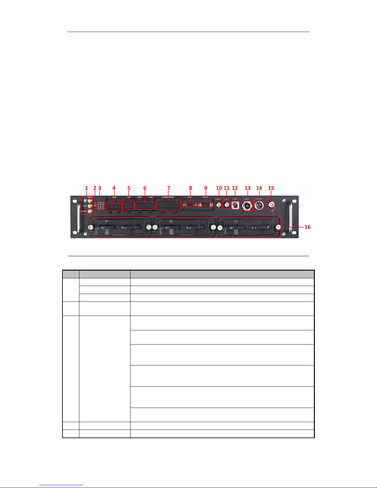
1.1 Interfaces
Figure 1. 1 Panel View
Table 1. 1 Interface’s Description
No.
Name
Description
1
GNSS
GNSS antenna interface
WIFI
Wi-Fi antenna interface. (only supported by the “/GW” devices)
M-ANT
3G antenna interface
2
IR
IR: IR receiver
Receive IR signal from remote control.
3
Indicators
PWR: Power indicator
Turns green after device starts up; Turns red when device stands by.
RDY: Ready indicator
Turns green when the device starts up
REC: Record indicator
Turns green when recording; The light is out when all recording processes are
abnormal.
GNSS: GNSS indicator
No light when GNSS module is abnormal; Turns green when the GNSS module
works normally; Blinks in green after the positioning successful.
ANT: 3G indicator
Turns green when 3G module works normally; Blinks slowly in 3G registration;
Blinks frequently after successful 3G registration.
ALM: Alarm indicator
Turns red when alarm occurs.
4
SIM
SIM card slot.
5
LAN1
RJ45 network interface for debugging.
Page 11
Rail Network Video Recorder User Manual
10
No.
Name
Description
6
USB1
USB 3.0 interface.
USB2
7
ALARM&RS422
2-ch relay signal output.
8-ch relay signal input.
1 RS-422 interface
8
VGA
VGA output.
9
RS232
Serial interface.
10
A OUT
Audio output.
11
V OUT
Video output.
12
LINE
Interface for mobile intercom.
13
LAN2
M12 network interface for connecting IP cameras and network transmission.
14
110 VDC
Power supply.
15
Lock
Hard drive lock.
16
Hard Drive Enclosure
3 hard drive caddies for 2.5 inch SATA HDDs/SSDs
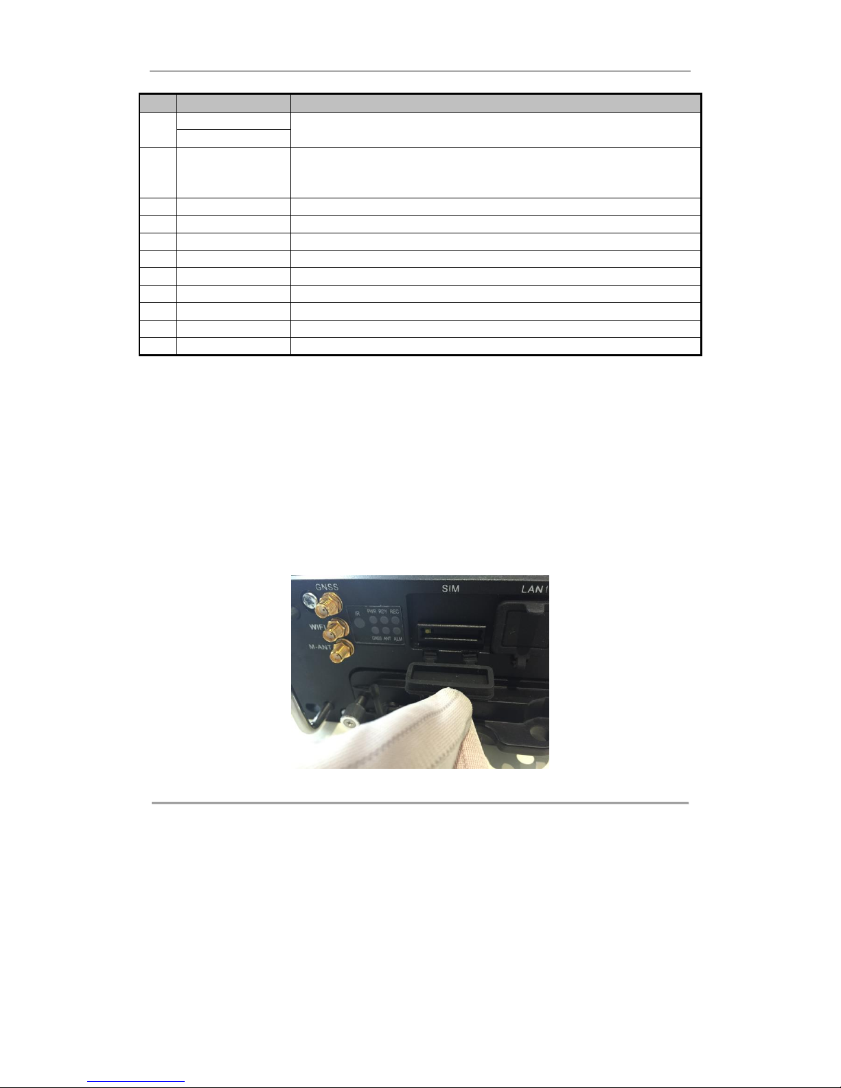
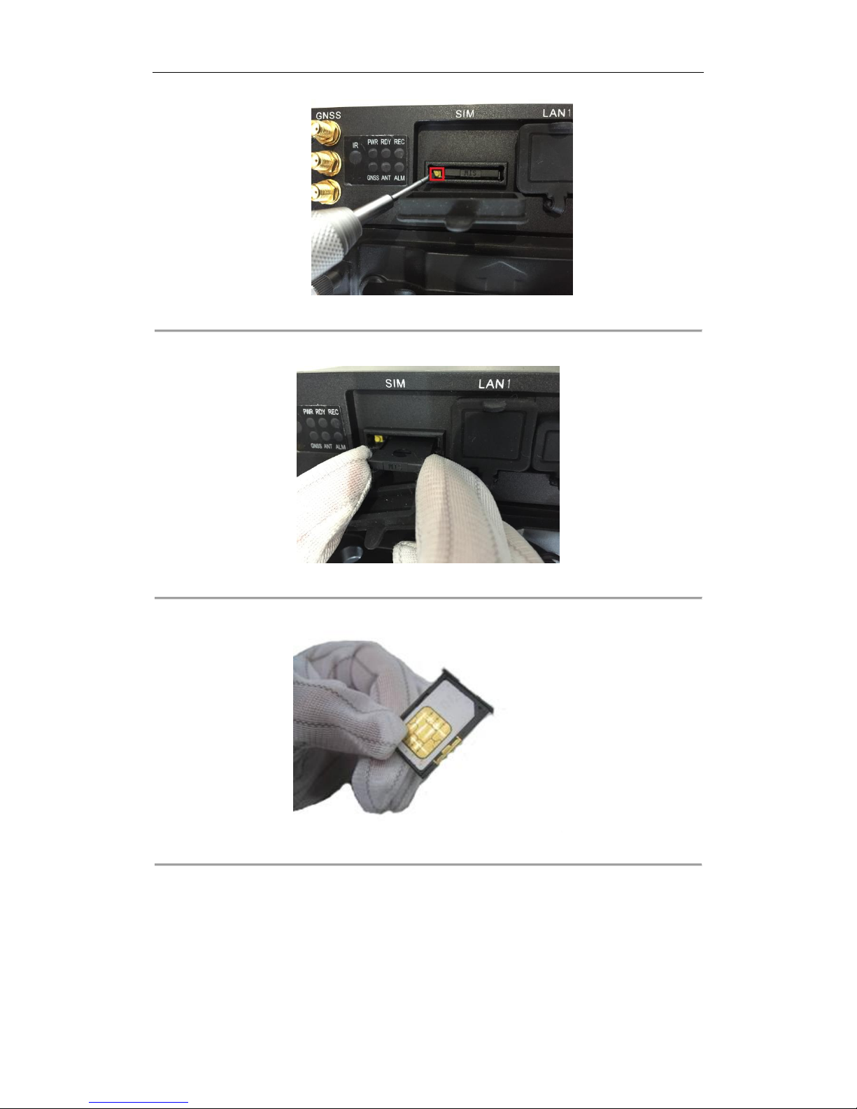
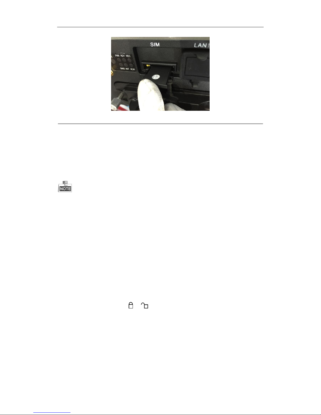
1.2 SIM Card Installation
Purpose:
Pluggable 3G module is designed for the Rail NVR and you should install the SIM card to realize the 3G function.
Perform the following steps to install the SIM card on the Rail NVR
Before you start:
Put on the antistatic gloves before the installation.
Steps:
1. Open the cover of SIM card slot.
Figure 1. 2 Open Cover
2. To pop up SIM card base, use a screw driver to press the yellow button marked by the red frame in the
following figure.
Page 12
Rail Network Video Recorder User Manual
11
Figure 1. 3 Press Yellow Button
3. Pull out SIM card base.
Figure 1. 4 Pull Out SIM Card Base
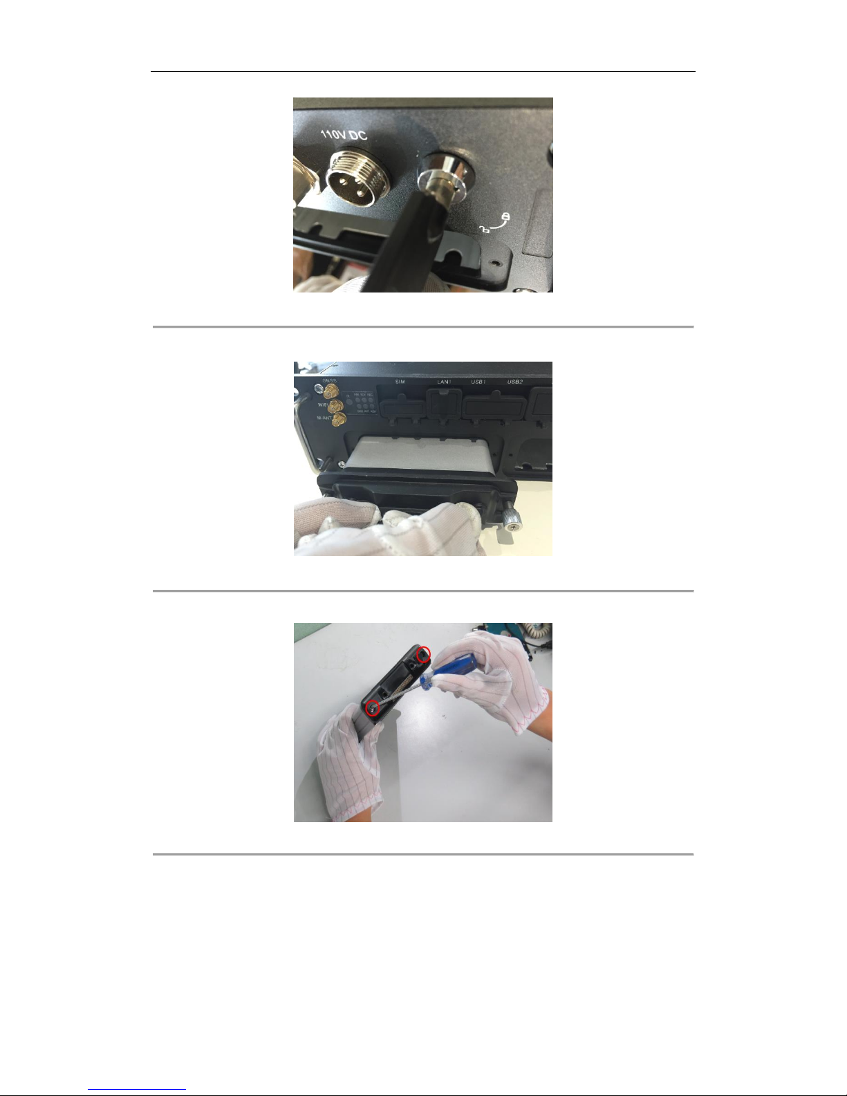
4. Place the SIM card into the SIM card base with the golden area facing up.
Figure 1. 5 SIM Card Base
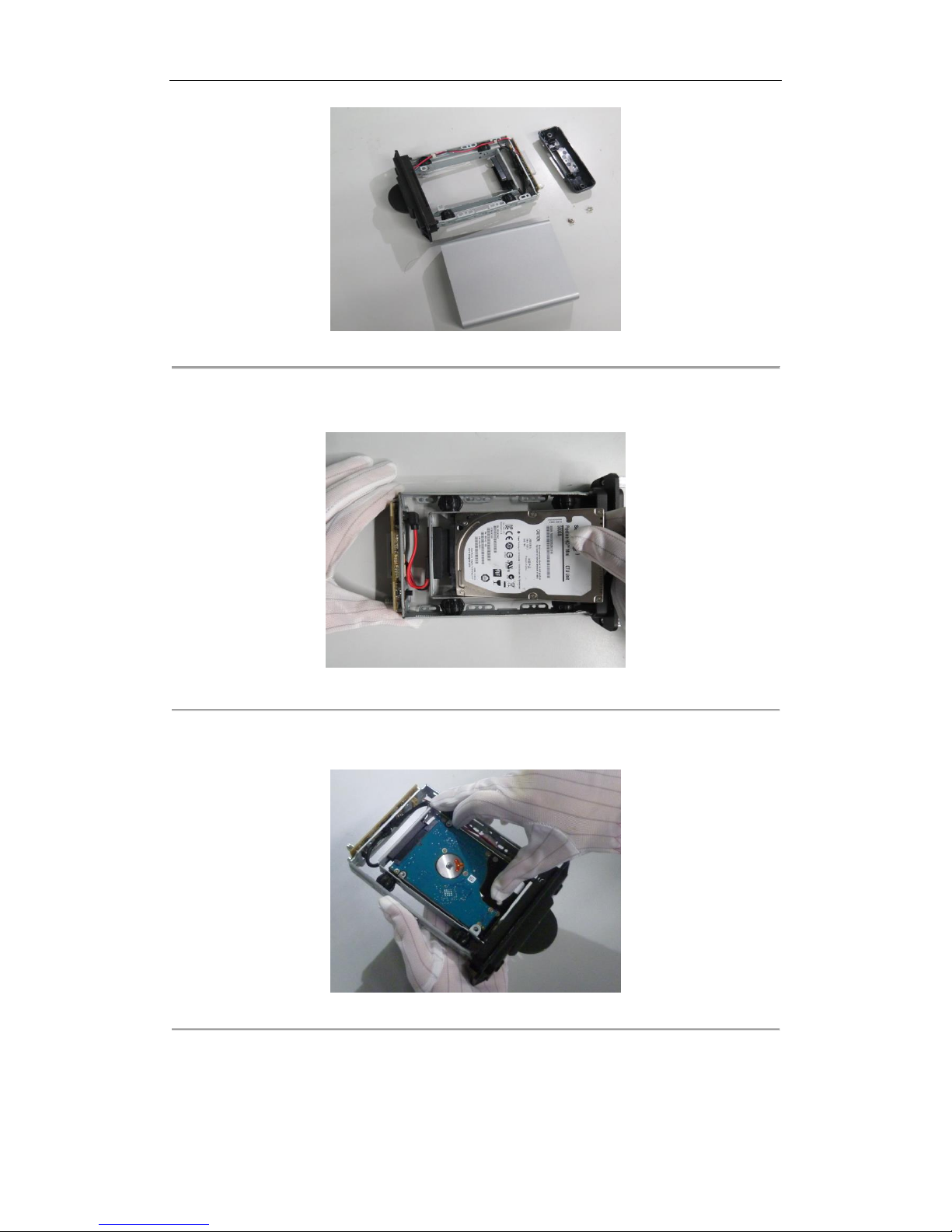
5. Push the SIM card base back into the SIM card slot bottom.
Page 13
Rail Network Video Recorder User Manual
12
Figure 1. 6 Push SIM Card Base into Slot
1.3 HDD Installation
Purpose:
3 HDD boxes are provied. You can install 2 HDDs for each HDD box. That is up to 6 HDDs can be installed. Perform
the following steps to install the HDD on the Rail NVR.
Use the factory recommended 2.5-inch HDD. You can ask technical support for information of factory
recommended.
For single HDD installation, the thickness of the HDD should be 9.5mm or 7mm; for double HDD installation,
the thickness of each HDD should be 7mm.
Initialize the HDD for recording after the installation. Otherwise, the system will give an audible warning for
HDD error. For details, see 4.1.1 Initializing the HDD.
Tools needed:
Two 2.5-inch SATA HDD
Antistatic gloves
Key of hard disk lock
Screwdriver
Screws
Steps:
1. Put on the anti-static gloves.
2. Insert the key and rotate it from to .
Page 14
Rail Network Video Recorder User Manual
13
Figure 1. 7 Unlock HDD Box
3. Pull out the HDD box.
Figure 1. 8 Pull HDD Box
4. Use a screwdriver to loosen and remove the two set screws marked in the figure.
Figure 1. 9 Loosen and Remove Screws
5. Separate the HDD box in to parts.
Page 15
Rail Network Video Recorder User Manual
14
Figure 1. 10 HDD Box Parts
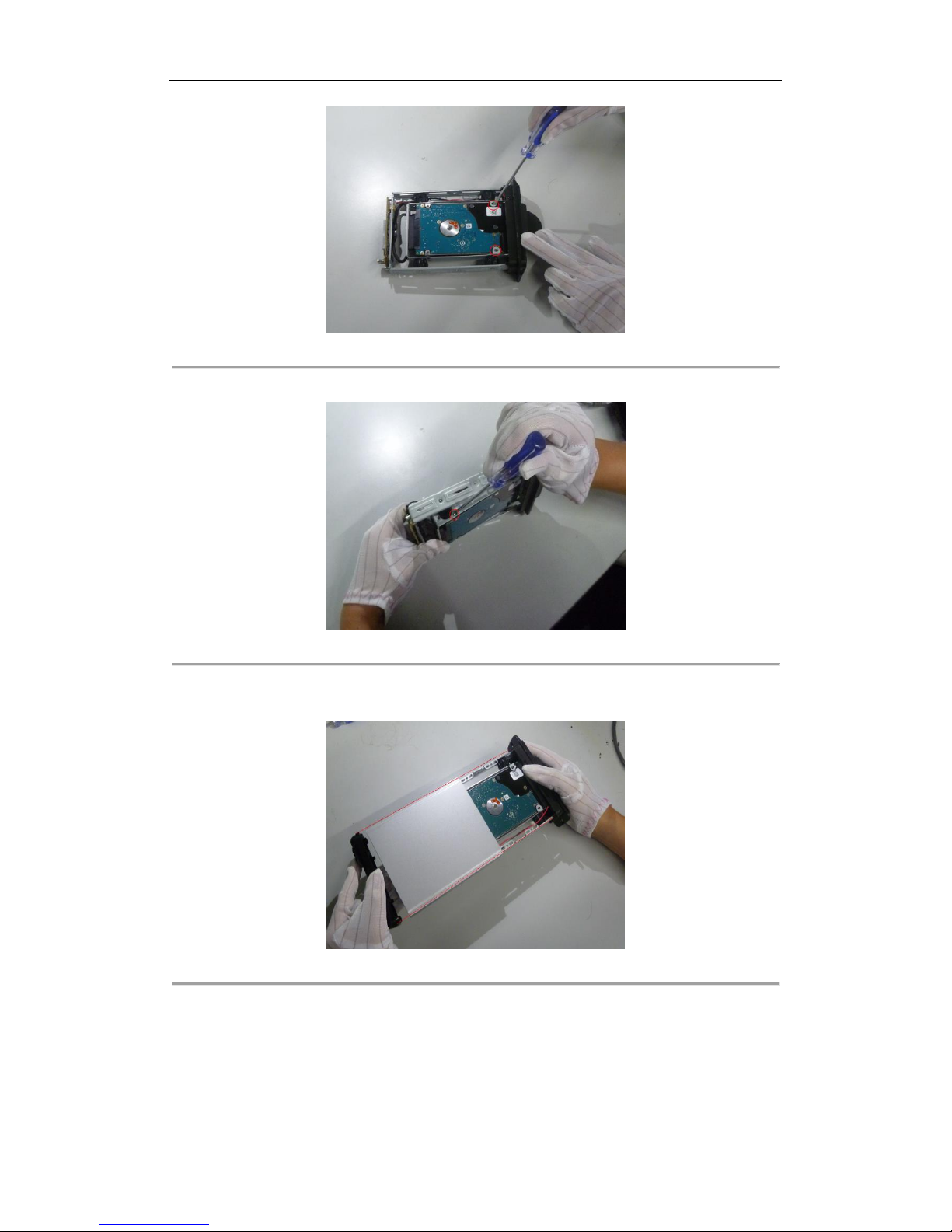
6. Place the first HDD into the HDD box and tightly insert the first HDD into the bottom, with the PCB facing
downward.
Figure 1. 11 Install the First HDD
7. Place the second HDD into the HDD box, with the PCB facing upward. After the HDD is totally placed into
the bracket, tightly insert the second HDD into the socket.
Figure 1. 12 Install the Second HDD
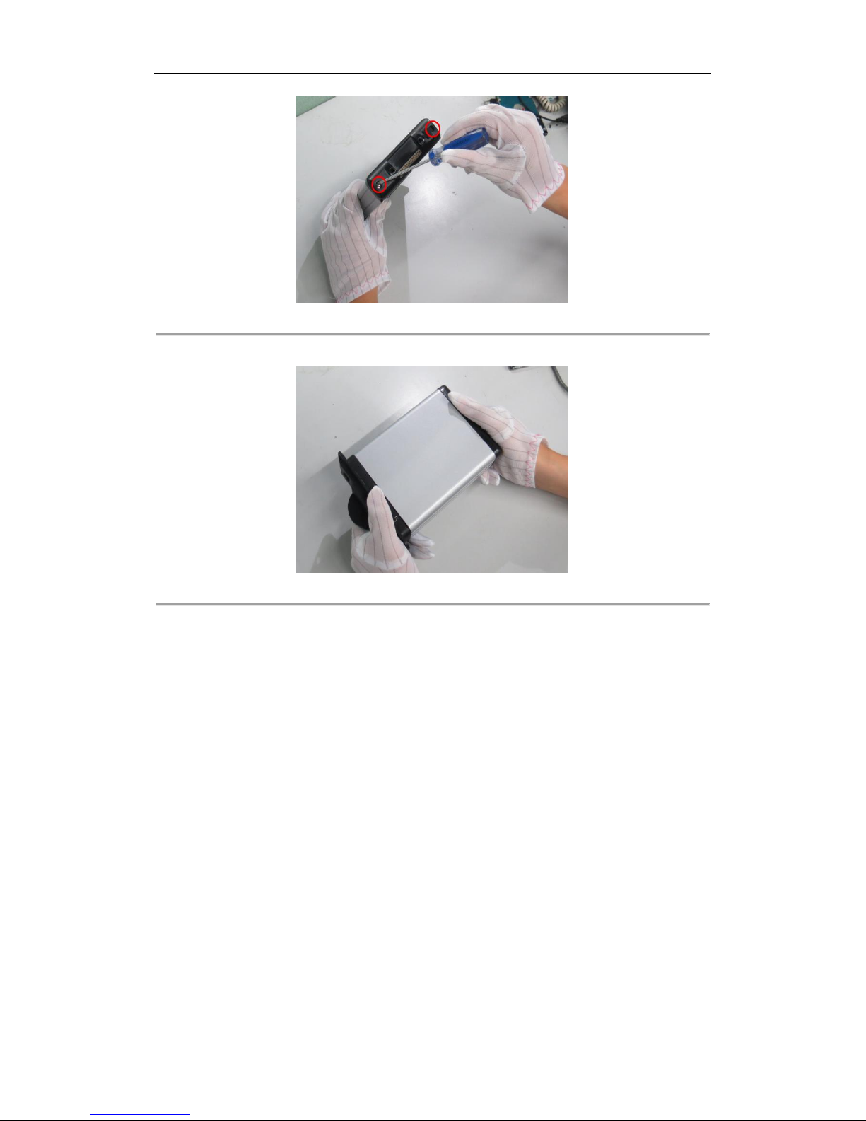
8. Tighten the two screws marked in the figure to fix the HDD. Do the same things to fix the other HDD at the
back side.
Page 16
Rail Network Video Recorder User Manual
15
Figure 1. 13 Fix HDDs
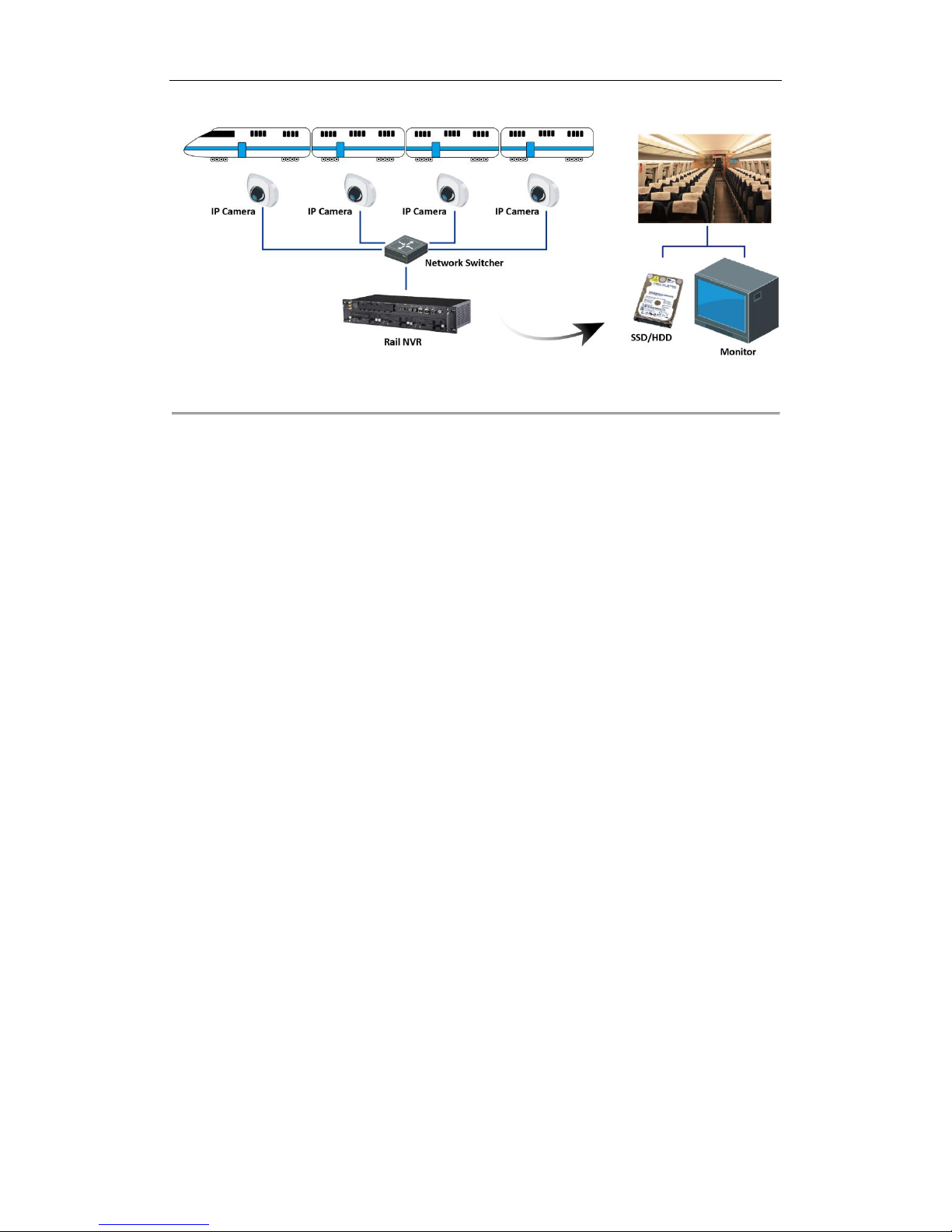
9. Tighten the 4 set screws on the side of the HDD box, shown as the following figure.
Figure 1. 14 Fix HDDs
10. Align the protective cover of the HDD box with the line marked in the figure, and assemble the whole HDD
box.
Figure 1. 15 Assemble HDD Box
11. Tighten the two set screws of the hard disk box, as shown in the figure.
Page 17
Rail Network Video Recorder User Manual
16
Figure 1. 16 Tighten Screws
12. Insert the HDD box back to the Rail NVR, and then tighten the screws clockwise.
Figure 1. 17 Insert HDD Disk Back to Rail NVR
1.4 Wiring
Purpose:
Wire and install your Rail NVR according to the following requirements.
Power supply
Rail NVR should connect with power supply which should be 110 VDC.
Network connection
LAN 2 is connected to a network switcher.
IP Camera
Make sure network communication between IP cameras to be added and your Rail NVR is well.
Video and audio output
If you want to operate Rail NVR via CVBS displayer, connect the A OUT and V OUT to a CVBS displayer.
If you want to operate Rail NVR via VGA displayer, before you start Rail NVR, connect the Rail NVR to
a VGA displayer via a VGA cable.
HDD
Install at least one HDD into the Rail NVR. For detailed steps, refer to 1.3 HDD Installation.
Mouse
Connect a mouse to one of the USB interface.
Page 18
Rail Network Video Recorder User Manual
17
Figure 1. 18 Wiring
Page 19
Rail Network Video Recorder User Manual
18
Chapter 2 Getting Started and Basic
Operations
Purpose:
Perform following sections to start and configure your Rail NVR. It makes you can perform basic operations,
including local menu operation, adding IP cameras, recording, etc.
2.1 Start-up
Before you start:
Wire your device according to 1.4 Wiring.
Step:
1. Insert the key into the Lock slot in front panel.
2. To start up device, rotate it from to . You will see the startup picture indicating device is starting.
Figure 2. 1 Startup Picture
2.2 Right-Click Menu and Main Menu
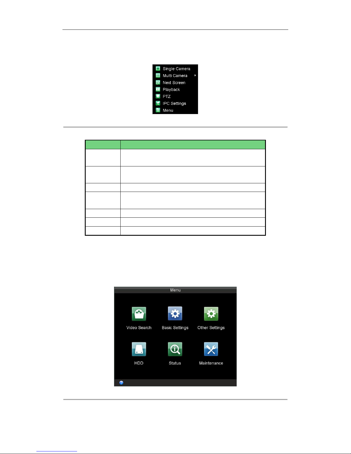
2.2.1 Right-Click Menu
Purpose:
Page 20
Rail Network Video Recorder User Manual
19
Right-click menu is a shortcut for several operations.
Step:
Right click on Live View. Then the right-click menu pops up.
Figure 2. 2 Right Click Menu
Table 2. 1 Right Click Menu Description
Item
Description
Single Camera
Switch to the single full screen by choosing camera number from the
drop-down list.
Multi Camera
Adjust the screen layout by choosing from the drop-down list. 2*2,
3*3, and 4*4 are provided.
Next Screen
Click to switch to the next screen.
Playback
Enter the playback interface and start playing back the video of the
selected channel immediately.
PTZ
Enter the PTZ control interface.
IPC Settings
You can add, edit, and delete IP cameras.
Menu
Enter the main menu of the system by right clicking the mouse.
2.2.2 Main Menu
Purpose:
To configure Rail NVR parameters, you need to enter main menu first.
Step:
Right click on Live View interface and click to select Menu item. Then Main Menu pops up.
Figure 2. 3 Main Menu
Page 21
Rail Network Video Recorder User Manual
20
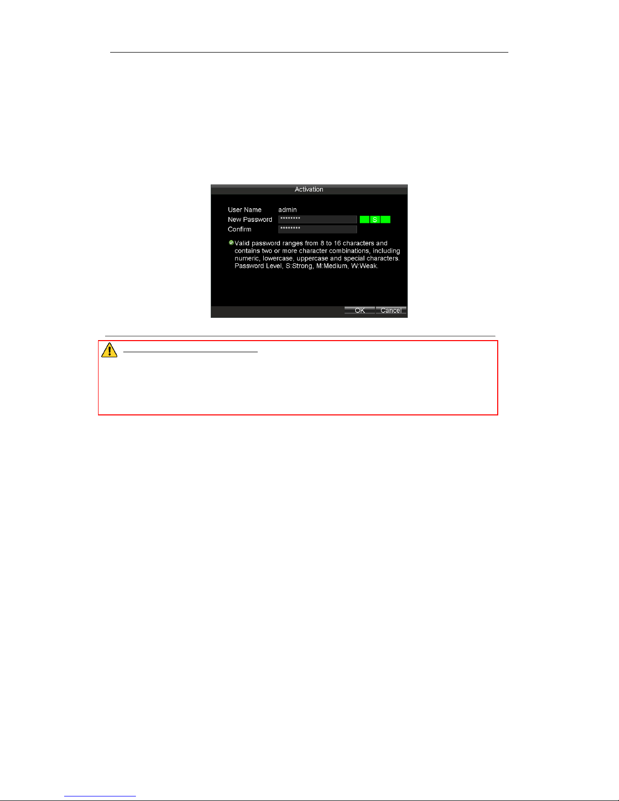
2.3 Setting Admin Password
Purpose:
For the first-time access, you need to activate the device by setting an admin password. No operation is allowed
before activation.
Steps:
1. Create the password by inputting the same password in the text field of New Password and Confirm.
Figure 2. 4 Settings Admin Password
STRONG PASSWORD RECOMMENDED– We highly recommend you create a strong password of your own
choosing (using a minimum of 8 characters, including upper case letters, lower case letters, numbers, and
special characters) in order to increase the security of your product. And we recommend you reset your
password regularly, especially in the high security system, resetting the password monthly or weekly can
better protect your product.
2. Click OK to save the password and activate the device.
2.4 IP Camera Management
Purpose:
You need to activate IP cameras first and then add them.
Before you start:
Ensure the network communication between IP camera and Rail NVR is well.
Steps:
To enter IP Camera Settings interface through main menu, do following steps:
Enter the Local Network Settings interface.
Main Menu > Other Settings > IPC Settings
To enter IP Camera Settings interface through right-click menu, do following step:
Right click on Live View interface and click to select IPC Settings in right-click menu.
Page 22
Rail Network Video Recorder User Manual
21
Figure 2. 5 IP Camera Settings
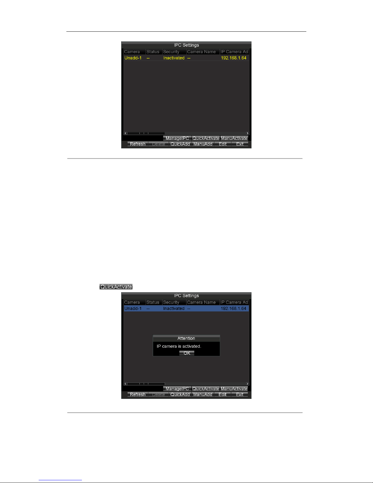
2.4.1 Activating IP Camera
Purpose:
Before adding the cameras, make sure the IP cameras to be added are in active status. Or you need to follow the
steps to activate it. Two methods are provided to activate IP camera, including quick activation and manual
activation.
Quick Activation
Purpose:
You can duplicate the Rail NVR’s password to IP camera by quick activation.
Steps:
1. Enter IPC Settings interface.
2. Click to select IPC you want to activate.
3. Click the button to start activation.
Figure 2. 6 Quick Activation
Page 23
Rail Network Video Recorder User Manual
22
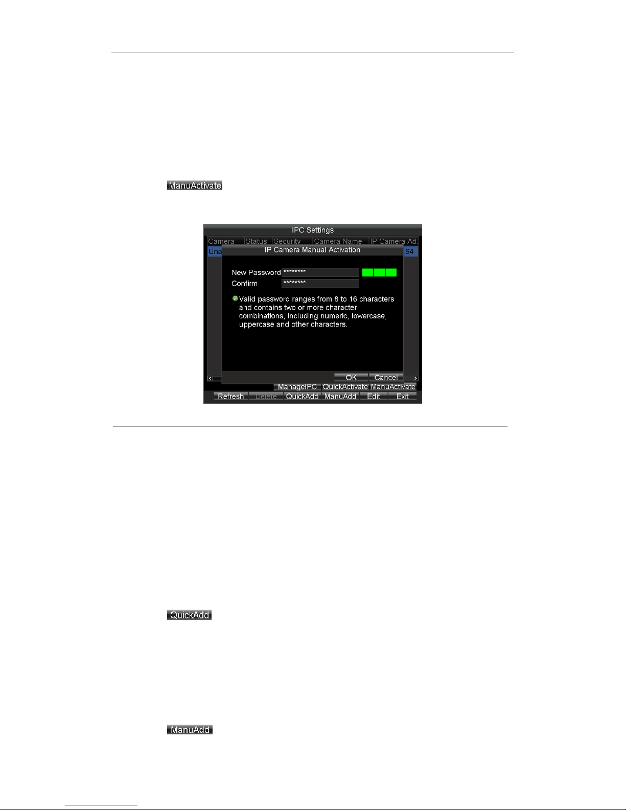
Manual Activation
Purpose:
You can activate the IP camera by setting your custom password.
Steps:
1. Enter IPC Settings interface.
2. Click to select IPC you want to activate.
3. Click the button to enter Manual Activation interface.
4. Create a password by inputting the same password in both New Password and Confirm.
5. Click OK to save the password and activate the password.
Figure 2. 7 Manual Activation
2.4.2 Adding IP Camera
Purpose:
The online IP cameras in the same network segment with the system would be displayed on a list.
Quick Adding
Purpose:
Quick adding is designed for the IPC with the same password with your Rail NVR.
Steps:
1. Enter IPC Settings interface.
2. Click to select the IPC you want to add.
3. Click the button to add it.
Manual Adding
Purpose:
You can manually add the IP cameras that are not in the same network segment with your Rail NVR.
Steps:
1. Enter IPC Settings interface.
2. Click the button to enter Add IP Camera Manually interface.
Page 24

Rail Network Video Recorder User Manual
23
3. Select the IP channel No. for the IP camera.
4. Input the required information, including the IP Address, Protocol, Port No., User Name, and Password.
5. Click the Protocol button, and you can customize the protocol according to the actual needs.
6. Click OK to add the IPC.
Up to 16 IP cameras can be added to the system.
The icon indicates the IP camera is offline.
The icon indicates the connected IP camera works properly.
Figure 2. 8 Manual Add
2.4.3 Managing IP Camera
Purpose:
You can modify IP address and password of IP cameras, including added IP cameras and unadded IP cameras.
You need to re-add the added IP cameras after you modify its password.
Steps:
1. Click to select an IP camera.
2. Click the button to enter Manage IPC Devices interface.
Page 25

Rail Network Video Recorder User Manual
24
Figure 2. 9 Manage IPC Devices
3. To modify IP address, do following steps:
1) Edit the IP Address.
2) Input Password (Old).
3) Click OK to save the new password.
4. To modify password, do following steps:
1) Input Password (Old).
2) Input the same password in Password (New) and Confirm.
3) Click OK to save the settings
2.4.4 Editing IP Camera
Purpose:
You can edit the added IP camera’s information. You needn’t re-add the IP camera after editing it.
Steps:
1. Click to select an added IP camera.
2. Click the button to enter Edit Added IP Camera.
3. Edit IP Address, Factory, Port, Sub Channel, User Name, or Password.
4. Click OK to save the settings.
Figure 2. 10 Edit IP Camera
Page 26

Rail Network Video Recorder User Manual
25
Chapter 3 Network Settings
Purpose:
You can configure local network, dialing, Wi-Fi parameters.
Figure 3. 1 Basic Settings
Table 3. 1 Sub-Menu Description
Sub-Menu Name
Description
Network
You can configure network parameters.
Dial
You can connect the device to the network and transmit the data after dialing to
internet.
WiFi
You can connect the device to the Wi-Fi networks and transmit the data via the
Wi-Fi.
Page 27

Rail Network Video Recorder User Manual
26
3.1 Local Network Settings
Purpose:
You can configure the basic network parameters and time synchronization parameters.
3.1.1 Network Settings
Purpose:
You need configure the basic network parameters to ensure well network communication.
Before you start:
Connect the LAN 2 to a network switch with network cable.
Port 1 and Port 2 respectively represent LAN 1 and LAN 2. LAN 1 is for debugging. LAN 2 is for connecting IP
cameras and network transmission.
Steps:
1. Enter the Local Network Settings interface.
Main Menu > Basic Settings > Network
2. Select Ethernet Port as Port 2.
3. Input the device IP address, Subnet Mask, Default Gateway, Preferred DNS Server, Alternate DNS Server in
the corresponding text fields.
Download Server IP: To upload videos to the Auto Backup Server, you need to input the IP address of
server, where the tool locates, in Download Server IP text field. You can ask technical support for the Auto
Backup Server.
IP address: LAN 2’s default IP address is 192.1.0.64.
4. Click OK to save the settings.
Figure 3. 2 Local Network Settings
3.1.2 Time Synchronization
Purpose:
You can synchronize Rail NVR’s time with NTP server.
Steps:
Page 28

Rail Network Video Recorder User Manual
27
1. Enter the Local Network Settings interface.
Main Menu > Basic Settings > Network
2. Click the Set button of NTP.
3. Check the checkbox of NTP to enable the NTP settings.
4. Input the Synchronization Interval.
5. Input the IP address of NTP Server.
6. Click OK to save the new settings and exit.
7. Click Apply to save the new settings and click OK to exit.
Figure 3. 3 NTP Settings
3.2 Dialing
Purpose:
You can connect the device to the network and transmit the data after dialing to internet.
Before you start:
Install a 3G SIM card on the Rail NVR. For details, refer to 1.2 SIM Card Installation.
Steps:
1. Enter the 3G Dialing Settings interface.
Main Menu > Basic Settings > Dial
Figure 3. 4 3G Dialing Settings
Page 29

Rail Network Video Recorder User Manual
28
2. Check the checkbox of Enable Dialing to enable the 3G dialing function of the device.
3. Select Network Mode as Auto, Adjust, or 3G Only.
Auto: the work mode is set as the detected stronger signal.
Adjust: the work mode is set as the 3G mode, as long as 3G signal is detected, even if it is weak.
3G Only: the network mode is set as 3G mode, that is 2G mode is not available.
4. Optionally, if you have a dedicated dialing network, you can configure the 3G VPDN (Virtual Private Dialup
Network) settings.
1) Click the Set button of More Settings.
2) Input the APN (access point name), Dialing Number, User Name, and Password.
3) Select the Verification Protocol.
4) Click OK to save the settings and exit the interface.
Figure 3. 5 APN
5. Click OK and reboot the device to activate the new settings.
6. You can view the dialing status on the Dialing Status interface (Main Menu > Status > Dial).
3.3 Wi-Fi
Purpose:
You can connect the device to the Wi-Fi networks and transmit the data via the Wi-Fi.
Step:
Enter the Wi-Fi Settings interface.
Main Menu > Basic Settings > WiFi
Page 30

Rail Network Video Recorder User Manual
29
Figure 3. 6 Wi-Fi Settings
3.3.1 Wi-Fi Settings
Steps:
1. Check the checkbox of Enable WiFi to turn on the Wi-Fi settings.
2. Select the Configuration file to which you want to connect.
Rail NVR can remember 5 Wi-Fi in the 5 configuration files. To connect Wi-Fi conveniently, configure Wi-Fi
parameters to which you connect frequently in these configuration files.
3. Input the network SSID (Service Set Identifier).
4. Configure the Security Type.
1) Select Security Type as None, WEP, WPA2-PSK, or WPA-PSK.
2) If Security Type is set as WEP, you need to configure Authentication, Key length, and so on.
If Security Type is set as WPA2-PSK or WPA-PSK, you need to configure Encryption Type and Key.
5. To configure automatically obtain Wi-Fi IP address and DNS server address, do following steps:
1) Click the Set button of More Settings.
2) Check the checkbox of DHCP and Auto-obtain DNS to obtain IP address and DNS server for Wi-Fi
network automatically. By default they are checked.
3) Click OK to save the settings and go back to upper menu.
6. Click OK to save the new settings and exit.
Page 31

Rail Network Video Recorder User Manual
30
Figure 3. 7 IP & DNS Settings for Wi-Fi
3.3.2 Wi-Fi AP Settings
Purpose:
To configure WiFi AP, WiFi Broadcast, and Wifi Hotspot, do following steps.
Steps:
1. To Click the Set button of WiFi AP.
2. Optionally, check the checkbox of Enable WiFi AP, Enable WiFi Broadcast, and Enable WiFi Hotspot.
To access internet via Rail NVR, check the checkboxes of Enable WiFi AP and Enable WiFi Hotspot.
3. Edit SSID and select Encrypt Type.
4. Click Settings of More to configure parameters of WiFi access point.
5. Click OK to save the settings and go back to upper menu.
6. Click OK to save the settings and exit.
Figure 3. 8 Wi-Fi Access Point Settings
Page 32

Rail Network Video Recorder User Manual
31
Chapter 4 Record Settings
4.1 Configuring Encoding Parameters
4.1.1 Initializing the HDD
Before you start:
Install at least one HDD on the Rail NVR for video data storage.
Steps:
1. Enter the HDD Management interface.
Main Menu > HDD
Figure 4. 1 HDD Management
2. Select the Hard Disk you want to format from the drop-down list.
3. Click the button and click OK in popup confirmation window to start formatting.
4.1.2 Configuring Record Settings
Purpose:
You can configure the transmission stream type, the resolution, frame rate, etc.
Steps:
1. Enter the Record Settings interface.
Main Menu > Basic Settings > Record
Page 33

Rail Network Video Recorder User Manual
32
Figure 4. 2 Record Settings
2. Select the camera from the drop-down list.
3. Configure the following settings:
Encoding Parameters
Main Stream (Normal): used for schedule recording;
Main Stream (Event): used for event recording;
Sub Stream: used for network transmission.
Stream Type
Video and Video & Audio are selectable.
Resolution
Select the resolution for the selected camera and stream type. WD1, 4CIF, 2CIF and CIF are selectable.
Bitrate Type
Variable and Constant are selectable.
The video quality is configurable when you select Variable to the bitrate type; and the video quality is
set as Medium by default and cannot be edited when you select Constant to the bitrate type.
Video Quality
If you select Variable to the bitrate type, you can set the video quality as Highest, Higher, Medium,
Low, Lower and Lowest.
Frame Rate
Frame rate refers to the frequency of the image frame after compression. With other parameters
constant, reduce the video frame rate, and you can lower the maximum bitrate to some extent.
Max. Bitrate(Kbps)
Select the fixed value provided by the system or customize the maximum bitrate as desired.
4. Click the Set button of Schedule to enter the record schedule interface.
1) Check the check box of Enable Schedule to enable the record schedule settings.
2) Select the day from the drop-down list for settings.
3) Check the checkbox of All Day to enable all-day recording, and then select the recording type from the
drop-down list.
You can also uncheck the checkbox of All Day, customize the time period for recording, and select the
recording type for each time period.
4) Click OK to save the new settings and exit.
Page 34

Rail Network Video Recorder User Manual
33
You can view the recording status on the Record Status interface (Main Menu>Status>Record).
5 recording types are selectable: Normal, Motion Detection, Alarm, Motion | Alarm and Motion
& Alarm.
Up to 8 time periods can be set for each day and each of the time periods cannot be overlapped.
Figure 4. 3 Record Schedule Settings
5. Click the Set button of More Settings to configure the pre-record and post-record time.
Pre-record: Normally used for the event (motion or alarm) triggered record, when you want to record
before the event happens. For example, when an alarm occurs at 10:00, if the pre-record time is set as
5 seconds, the camera records the alarm at 9:59:55.
Post-record: After the event finished, the video can also be recorded for a certain time. For example,
when an alarm ends at 11:00, if the post-record time is set as 5 seconds, the camera records till
11:00:05.
6. Optionally, you can select the camera and click Copy to copy the current settings to the selected camera.
7. Click Apply to save the settings and click OK to exit.
4.2 Configuring Motion Detection Record
Purpose:
In the motion detection record, once a motion event occurs, the device starts to record and multiple linkage
actions will be triggered.
Steps:
1. For detailed steps, you can refer to 7.2.5 Configuring Motion Detection.
2. Enter the Record Settings interface, and select Motion as the record type to set the arming schedule of
motion detection record.
Main Menu > Basic Settings > Record Settings > Schedule
4.3 Configuring Alarm Triggered Record
Purpose:
Page 35

Rail Network Video Recorder User Manual
34
Follow the procedure to configure alarm triggered recording.
Steps:
1. For detailed steps, refer to 7.5.2 Alarm Input Settings.
2. Enter the Record Settings interface to and select Alarm as the record type.
Main Menu > Basic Settings > Record Settings > Schedule
Page 36

Rail Network Video Recorder User Manual
35
Chapter 5 Video Search and Export
Purpose:
You can search and play back the videos stored on the device.
Step:
Enter the Video Search interface.
Main Menu > Video Search
Figure 5. 1 Video Search Interface
5.1 Searching Videos
Purpose:
You can search and play back the videos stored on the device.
Steps:
1. Enter the Video Search interface.
Main Menu > Video Search
2. Specify the Camera and Video Type from the drop-down list.
3. Specify the Start Time and End Time for search.
4. Click Search to search. If there are videos match the search conditions, they would be listed in the Search
Results interface. Or the prompt “No record file found.” appears.
Page 37

Rail Network Video Recorder User Manual
36
Figure 5. 2 Search Results.
5.2 Playing Video
Purpose:
You can play back the history videos.
5.2.1 Playing by Time
Purpose:
You can specify a period, and then start playing back all the video segments in the period continually.
Steps:
1. Enter the Video Search interface.
Main Menu > Video Search
2. Specify the search conditions, including Camera, Video Type, Start Time, and End Time.
3. Click Play to start playback. If there are videos match the search conditions, the playback window appears.
Or the prompt “No record file found.” appears.
5.2.2 Playing by File
Purpose:
You can specify a video file to playback.
Steps:
1. Search out the videos to play back. For details, refer to 5.1 Searching Video.
Page 38

Rail Network Video Recorder User Manual
37
Figure 5. 3 Search Results
2. Search Results
3. Click to select the videos to playback.
4. Click Play to start playing it.
Figure 5. 4 Playback Window
5.2.3 Managing Playback Control Bar
Purpose:
You can mute playback and clip videos during playback process.
Steps:
To exit playback, do following steps:
1. Right click the playback window.
2. Click Exit to exit playback process.
Figure 5. 5 Playback Right-Click Menu
To hide playback control bar, do following steps:
1. Right click the playback window.
Page 39

Rail Network Video Recorder User Manual
38
2. Click Control Panel to hide control bar.
3. Repeat step 1) to 2) to show control bar.
Figure 5. 6 Control Bar
To mute playback process, do following steps:
1. Click the icon in control bar to mute.
2. Click the icon again to turn on audio.
To clip videos, do following steps:
1. Connect a USB flash drive to the USB interface of Rail NVR.
2. Click the icon in control bar to start clip.
3. Click the icon again to stop clip.
4. Repeat step 2) to 3) to clip more.
5. When exit the playback, the prompt reminds you to export clips appears, click OK in the prompt to export
the video clips to USB flash drive.
Figure 5. 7 Export Clips
5.3 Exporting Video
Purpose:
To back up video, you can export videos to USB flash drive.
Steps:
1. Connect a USB flash drive to the USB interface of Rail NVR.
2. Search out videos you want to export. For details, refer to 5.1 Searching Video.
3. Check the checkboxes of videos you want to export.
4. Click Export to start exporting. The exported videos would be saved in the connected USB flash drive.
Figure 5. 8 Export Succeeded
Page 40

Rail Network Video Recorder User Manual
39
Chapter 6 Basic Settings
Purpose:
There are nine sub-menus provided in Basic Settings menu.
Figure 6. 1 Basic Settings
Table 6. 1 Sub-Menu Description
Sub-Menu Name
Description
Record
You can configure the parameter for videos.
Serial Port
Two types of serial ports are provided: RS-232 and RS-485.
Start
You can specify the startup/shutdown time for the Rail NVR.
Position
The built-in GNSS module supports GPS (Global Positioning System), contributing to
the device positioning and speed limit alarm.
G-Sensor
G-Sensor detects and records the acceleration speed information in 3-axial (X, Y, Z)
directions.
Platform
The Rail NVR can be remotely accessed via iVMS platform. Make sure the
parameters configured are valid for the platform.
Page 41

Rail Network Video Recorder User Manual
40
6.1 Serial Port
Purpose:
Two types of serial ports are provided: RS-232 and RS-485.
Step:
Enter the Serial Port Settings interface to configure the parameters.
Main Menu > Basic Settings > Serial Port
6.1.1 RS-232
Steps:
1. Select Serial Port Type as RS-232.
2. Select Parity.
3. Select Used As as Parameters Configuration or Transparent Channel.
Parameters Configuration: Connect a PC to the DVR through the PC serial port. DVR parameters can
be configured by using software such as HyperTerminal. The serial port parameters must be the same
as of the device when connecting with the PC serial port.
Transparent Channel: Connect a serial device directly to the device. The serial device will be
controlled remotely by the PC through the network and the protocol of the serial device.
4. Click OK to save the settings.
Figure 6. 2 RS-232
6.1.2 RS-485
Steps:
1. Select Serial Port Type as RS-485.
2. Configure Baudrate and Parity.
The RS-485 port can be used for transparent channel only.
3. Click OK to save the settings and exit.
Page 42

Rail Network Video Recorder User Manual
41
Figure 6. 3 RS-485
6.2 Start Control
Purpose:
You can specify the startup/shutdown time for the Rail NVR.
Steps:
1. Enter the Start Control interface.
Main Menu > Basic Settings > Start
2. Select Auto Work Type as Auto Working.
3. Select the Date on which you want to start up/shut down the device automatically.
4. Specify the Time Segment for the device to start up and shut down.
5. Optionally, you can copy the settings to other days in the week.
6. Click OK to save the new settings and exit.
Two periods can be configured for each day. And the time periods can’t be overlapped each other.
Figure 6. 4 Start Control-Auto Working
Page 43

Rail Network Video Recorder User Manual
42
6.3 Position
Purpose:
The built-in GNSS module supports GPS (Global Positioning System), contributing to the device positioning and
speed limit alarm.
Steps:
1. Enter the Satellite Positioning Settings interface.
Main Menu > Basic Settings > Position
Figure 6. 5 Satellite Positioning Settings
2. Select the mode of the Position Module. Only Built-in is provided.
Built-in: Obtain data from the satellite positioning module built in the Rail NVR.
3. Check the checkbox of Satellite Time Adjusting and then select the time zone in which the device locates.
4. Select the Speed Unit and input the Speed Limit value.
5. Set the linkage actions for speeding alarm, including Audio Alarm and Alarm Output. For details of alarm
output settings, see 7.5.3 Alarm Output Settings.
6. Click Set of Display Channel to configure display channel. The device positioning information would be
displayed on the selected channels.
7. Click OK to save the new settings and exit.
8. You can view the device positioning status on the Positioning Status interface (Main Menu > Status >
Position).
6.4 G-Sensor
Purpose:
G-Sensor detects and records the acceleration speed information in 3-axial (X, Y, Z) directions.
Before you start:
Connect an external sensor to the device for obtaining and providing the acceleration speed in 3-axial directions.
Steps:
1. Enter the G-Sensor Settings interface.
Main Menu > Basic Settings > G-Sensor
Page 44

Rail Network Video Recorder User Manual
43
Figure 6. 6 G-Sensor Settings
2. Select the mode of G-sensor Module. Only built-in module is provided.
Built-in: The G-sensor is built in the Rail NVR.
3. Set the limit value for acceleration alarm in X, Y and Z directions.
X, Y and Z represent the direction of acceleration and the unit of alarm value is G (G=9.8 m/s2).
4. Set the linkage actions for acceleration alarm, including Audio Alarm and Alarm Output. For details of alarm
output settings, see 7.5.3 Alarm Output Settings.
5. Click OK to save the new settings and exit.
6. You can view the G-sensor status on the G-sensor Status interface (Main Menu > Status > G-sensor).
6.5 Platform
Purpose:
The Rail NVR can be remotely accessed via iVMS platform. Make sure the parameters configured are valid for the
platform.
Before you start:
Create the device ID of Rail NVR on the iVMS platform.
Ensure the network communication between Rail NVR and platform is well.
Steps:
1. Enter the Platform Settings interface.
Main Menu > Basic Settings > Platform
Page 45

Rail Network Video Recorder User Manual
44
Figure 6. 7 iVMS Platform Settings
2. Select Platform as Platform iVMS or 3G_SDK.
Platform WVS: Reserved
Platform iVMS: It refers to iVMS-7200.
3G_SDK: It refers to platform developed by yourself based on the SDK provided by our company.
3. Configure the following parameters:
Server IP: Input the static IP address of iVMS server.
Port No.: Input the port No. of iVMS server.
Device Register ID: The ID of the Rail NVR registered on the iVMS platform.
Register Password: Only needed when Platform is selected as 3G_SDK.
4. Click OK and reboot the device to activate the new settings.
5. You can view the platform status on the Platform Status interface (Main Menu > Status > Plat).
Page 46

Rail Network Video Recorder User Manual
45
Chapter 7 Other Settings
Purpose:
There are ten sub-menus provided in Basic Settings menu.
Figure 7. 1 Other Settings
Table 7. 1 Sub-Menu Description
Sub-Menu Name
Description
Display
You can set the system time, select the CVBS output standard, enable the password,
configure the DST settings, etc.
Camera
You can configure the OSD (On Screen Display) settings which includes the display of
camera name, date and week, and the corresponding position information.
User
You can add and manage users here. The admin user has all the operation
permissions of the device.
Preview
You can configure the dwell time of live view window, set the camera order,
enable/disable the audio preview, etc.
Exception
You can configure the handle action for exceptions.
Alarm In
You can configure the settings for alarm input, including trigger level, arming
schedule, alarm linkage actions, etc.
Alarm Out
You can configure the arming schedule, alarm duration time, alarm name for alarm
output.
Firewall
You can enable SSH service and add white list for Rail NVR.
PTZ
You can set the parameters for PTZ.
Page 47

Rail Network Video Recorder User Manual
46
7.1 Display Settings
Purpose:
You can set the system time, select the CVBS output standard, enable the password, configure the DST settings,
etc.
Steps:
1. Enter the Display Settings interface.
Main Menu > Other Settings > Display
The system language is set as English by default and is not editable.
Figure 7. 2 Display Settings
Optionally, you can do following steps to configure the following parameters according to your needs.
Set the CVBS Output Standard as NTSC or PAL according to the actual video input standard.
Click and to Set the System Time.
Select the VGA Resolution from the drop-down list.
The VGA resolution is only configurable when the Rail NVR is connected to a VGA monitor. And you can set it
as 1024*768/60Hz, 1280*720/60Hz, 1280*1024/60Hz, 1600*1200/60Hz, or 1920*1080/60Hz.
Check the checkbox of Enable Password to enable the password authentication before operations.
Click the Set button of DST Settings, and you can configure the DST (Daylight Saving Time) for the system.
Perform the following steps to configure the DST settings.
1) Check the checkbox of Enable DST.
2) Set the start time and end time for the DST period.
3) Select the DST bias from the drop-down list.
4) Click Apply to save the settings and click OK to exit.
Page 48

Rail Network Video Recorder User Manual
47
Figure 7. 3 DST Settings
Click the Set button of Advance Settings, and you can configure the advanced parameters for display.
Device Name: Input the system name as desired in the text field.
Device No.: Edit the device No. for remote control. The device No. ranges from 1 to 255. The default
device No. is 255.
It is recommended not to modify the Device No.. Otherwise, you need to input the Device No. on the
remote control every time you use it.
Brightness of CVBS: Adjust the video output brightness.
Menu Transparency: The transparency proportion of the menu displayed on the live view interface.
You can set it as 1:3, 1:1, 3:1 or Non-transparent.
The smaller the proportion value is, the more transparent the menu is.
When the Not Transparent is selected, only the menu is displayed on the interface.
Operation Timeout: If no operations are done during the selected time, the live view interface will be
displayed automatically.
Figure 7. 4 Advanced Settings
Page 49

Rail Network Video Recorder User Manual
48
2. Click Apply to save the settings and click OK to exit.
7.2 Camera Settings
Purpose:
You can configure OSD, image, mask, video tamper-proof, motion detection, and video loss parameters.
7.2.1 OSD Settings
Purpose:
You can configure the OSD (On Screen Display) settings which include the display of camera name, date and week,
and the corresponding position information.
Steps:
1. Enter the Camera Settings interface.
Main Menu > Other Settings > Camera
Figure 7. 5 Camera Settings
2. Select the Camera from the drop-down list.
3. Input the Camera Name as desired in the text field.
4. Check the checkboxes of Display Camera Name, Display Date, or Display Week, thus to display camera
name, date, and week in the live view interface for the selected camera.
5. Select the Date Format and Time Format according to the actual needs, and then select the OSD property.
6. To adjust OSD Position, do following steps:
1) Click the OSD Position button
2) Drag the red bar which represents the Date/Time Position and place it in the position according to
your needs.
3) Right click and click to select Camera Name Position item.
4) Drag the red bar which represents the Camera Name Position and place it in the position according to
your needs.
5) Right click and click to select Exit item.
7. Click Apply to save the new settings and click OK to exit.
Page 50

Rail Network Video Recorder User Manual
49
Figure 7. 6 More Setting
7.2.2 Image Settings
Purpose:
Perform the following steps to adjust the video parameters, including Brightness, Contrast, Saturation and Hue.
Steps:
1. Enter Camera Settings interface.
Main Menu > Other Settings > Camera Settings
2. Click the Set button of More Settings.
3. Click the Set button of Image Settings to enter the Image Settings interface.
4. Drag the slider to adjust value.
5. You can click Default to restore the default video parameters.
6. Click OK to save the new settings.
Figure 7. 7 Image Settings Interface
7.2.3 Configuring Mask
Purpose:
The privacy mask can be set to prevent some certain spots in the surveillance area from being viewed or
recorded. Perform the following steps to set a privacy mask:
Steps:
1. Enter Camera Settings interface.
Main Menu > Other Settings > Camera Settings
2. Click the Set button of More Settings.
3. Check the checkbox of Mask to enable the privacy mask function.
4. Click the Area Settings button to set the mask area on the live view interface.
5. Drag to draw a rectangle.
6. Repeat step 3 to draw more rectangles.
7. Right click and select Exit.
Page 51

Rail Network Video Recorder User Manual
50
Up to 4 mask areas can be configured for each channel.
The mask area information of one channel cannot be copied to another one.
You cannot view the image of the mask area either from the live view interface or videos.
7.2.4 Configuring Video Tampering Alarm
Purpose:
A tampering alarm is triggered when the camera is covered and the monitoring area cannot be viewed. Linkage
actions including audible warning, alarm output, etc., can be set to handle it.
Steps:
1. Enter the Advanced Camera Settings interface.
Main Menu > Other Settings > Camera Settings
2. Click the Set button of More Settings.
3. Check the checkbox of Tamper-proof to enable the tamper-proof function.
4. To set tamper-proof Area, do following steps:
1) Click the Area Settings button.
The video tampering alarm can be triggered only when the view of the camera is fully covered. The
regional video tampering alarm function is reserved.
2) Draw a rectangle as the tamper-proof area.
3) To configure tamper-proof sensitivity, do following steps:
a) Right click and click to select Sensitivity.
b) Select Sensitivity as Low, Media, or High.
c) Click OK to exit
4) Right click and click to select Exit to exit area settings interface.
5. Click the Handle button of tamper-proof to set the arming schedule and alarm linkage actions.
1) Select the day from the drop-down list, and set the arming schedule for the alarm linkage actions.
2) Optionally, you can copy the current settings to other days in the week.
3) Check the checkboxes to enable the corresponding linkage actions.
Pop-up Image on Monitor
When an alarm is triggered, the local monitor displays the video image from the alarming channel
configured for full screen monitoring.
Audio Warning:
Trigger an audible beep when an alarm is detected.
Trigger Alarm Output:
Trigger an alarm output when an alarm is detected.
4) Click Apply to save the new settings and click OK to exit.
Page 52

Rail Network Video Recorder User Manual
51
Figure 7. 8 Linkage Action of Tamper-proof
6. Click Apply to save the new settings and click OK to exit.
7.2.5 Configuring Motion Detection
Purpose:
In the motion detection record, once a motion event occurs, the device starts to record and multiple linkage
actions will be triggered.
Steps:
1. Enter the Advanced Camera Settings interface.
Main Menu > Other Settings > Camera Settings
2. Click the Set button of More Settings.
Figure 7. 9 Motion Detection Settings
3. Check the checkbox of Motion Detection to enable the motion detection function.
4. To draw area for motion detection, do following steps:
1) Click the Area Settings button.
2) Drag to draw red frame which is motion detection area.
Optionally, you can right click and select Full-Screen Detection to draw a full-screen area.
3) To set Sensitivity of motion detection, do following steps:
a) Right click and select Sensitivity.
b) Select Sensitivity and click OK to save the settings.
4) Right click and click to select Exit.
Page 53

Rail Network Video Recorder User Manual
52
5. Click the Handle button of motion detection to set the arming schedule and alarm linkage actions.
1) Select the day from the drop-down list, and set the arming schedule for the alarm linkage actions.
2) Optionally, you can copy the current settings to other days in the week.
3) Check the checkboxes to enable the corresponding linkage actions.
Pop-up Image on Monitor
When an alarm is triggered, the local monitor displays the video image from the alarming channel
configured for full screen monitoring.
Audio Warning:
Trigger an audible beep when an alarm is detected.
Trigger Alarm Output:
Trigger an alarm output when an alarm is detected. For details of alarm output settings, see 7.5.3
Alarm Output Settings.
4) Click the Set button of Triggered Camera to select the channel to be triggered.
5) Click Apply to save the new settings and click OK to exit.
Figure 7. 10 Linkage Actions of Motion Detection
6. Click Apply to save the new settings and click OK to exit.
7.2.6 Configuring Video Loss
Purpose:
When the device cannot receive video signal from the front-end devices, the video loss alarm will be triggered.
Linkage actions including audible warning, alarm output, etc., can be set to handle it.
Steps:
1. Enter the Advanced Camera Settings interface.
Main Menu > Other Settings > Camera Settings
2. Click the Set button of More Settings.
3. Check the checkbox of Video Loss Detection to enable the video loss detection settings.
4. Click the Handle button of Video Loss Detection, and you can set the arming schedule and alarm linkage
actions for video loss alarm. For detailed steps, see step 5 of 7.2.4 Configuring Video Tampering Alarm.
5. Click Apply to save the new settings and click OK to exit.
Page 54

Rail Network Video Recorder User Manual
53
7.3 User Settings
Purpose:
You can add and manage users here. The admin user has all the operation permissions of the device.
7.3.1 Adding User
Steps:
1. Enter the User Management interface.
Main Menu > Other Settings > User
Figure 7. 11 User Management
2. Click the Add button to enter the Add User interface.
Figure 7. 12 Add User
3. Input the information of the new user, including User Name, Password, and Confirm Password.
STRONG PASSWORD RECOMMENDED–We highly recommend you create a strong password of your own
choosing (Using a minimum of 8 characters, including at least three of the following categories: upper
case letters, lower case letters, numbers, and special characters.) in order to increase the security of your
product. And we recommend you reset your password regularly, especially in the high security system,
resetting the password monthly or weekly can better protect your product.
Page 55

Rail Network Video Recorder User Manual
54
4. Select the user Level from the drop-down list.
Operator: The operator has permissions of Preview, Playback, Backup, Log Search, and Parameters
Settings.
Guest: The Guest has permission of Preview, Playback, Backup, and Log Search.
5. Click the OK button to save the settings and go back to the User Management interface.
6. You can click the Delete button to delete the selected user and click the Modify button to modify the user
information.
7.3.2 Modifying User
Steps:
1. Click to select the user you want to modify.
2. Click Modify.
3. Edit the Password and Confirm. For admin user, you need to input Current Password for authority.
4. Click OK to save the settings.
STRONG PASSWORD RECOMMENDED–We highly recommend you create a strong password of your
own choosing (Using a minimum of 8 characters, including at least three of the following categories:
upper case letters, lower case letters, numbers, and special characters.) in order to increase the security
of your product. And we recommend you reset your password regularly, especially in the high security
system, resetting the password monthly or weekly can better protect your product.
Figure 7. 13 Modify User
7.3.3 Deleting User
Steps:
1. Click to select the user you want to modify.
2. Click Delete.
3. Click OK in popup confirmation window to delete it.
7.4 Preview Settings
Purpose:
You can configure the dwell time of live view window, set the camera order, enable/disable the audio preview,
etc.
Page 56

Rail Network Video Recorder User Manual
55
Steps:
1. Enter the Preview Settings interface.
Main Menu > Other Settings > Preview
Figure 7. 14 Preview Settings
2. Select the Video Output from the drop-down list according to the actual needs.
3. Select the Preview Mode, Dwell Time for live view,
4. Check the checkbox of Enable Audio Output to enable the function.
Preview Mode: select the window division mode for live view.
Dwell Time: the switch interval of the live view screen. The screen will be switched to the next one
after the selected dwell time.
Enable Audio Output: Enables/disables audio output for the selected video output.
5. Click the Set button to set the Camera Order.
Perform the following steps to set the camera order for display:
1) Click and to adjust display channel for each window.
The character “X” means no camera will be displayed on the selected window.
2) Click OK to save the new settings and exit.
Figure 7. 15 Camera Order
Page 57

Rail Network Video Recorder User Manual
56
6. Click the Apply button to save the new settings and click OK to exit.
7.5 Alarm Settings
Purpose:
You can configure handling method for alarm events.
7.5.1 Exception Settings
Purpose:
Exception Settings refer to the handling methods of various exceptions, e.g.
HDD Full: The HDD is full.
HDD Error: Writing HDD error, unformatted HDD, etc.
Network Disconnected: Network cable is disconnected.
IP Conflicted: Duplicated IP address.
Illegal Login: Incorrect user id or password.
Video Exception: frame rate is too low.
Abnormal Recording: No space for saving recorded files.
Steps:
1. Enter the Exception interface.
Main Menu > Other Settings > Exception
2. Select the Exception Type.
3. Set the alarm linkage actions, including Audible Warning and Alarm Output.
4. Click Apply to save the new settings and click OK to exit.
Figure 7. 16 Exception
7.5.2 Alarm Input Settings
Purpose:
Configure the settings for alarm input, including trigger level, arming schedule, alarm linkage actions, etc.
Steps:
1. Enter the Alarm Input Settings interface.
Page 58

Rail Network Video Recorder User Manual
57
Main Menu > Other Settings > AlarmIn
Figure 7. 17 Alarm Input Settings
2. Select the Alarm Input No..
3. Input the Alarm Name as desired in the text field.
4. Set the Alarm Type as NO (Normally Open) or NC (Normally Closed) of the alarm input according to the
actual needs.
5. Click the Set button of Trig Record Channel to select the alarm triggered recording channel(s). The selected
channel(s) will start to record when a connected alarm input occurs.
6. To configure the Schedule, do following steps:
1) Click the Set button of Schedule to set the arming schedule for alarm inputs.
2) Optionally, you can click Copy to copy the current settings to other days in the week.
Up to 8 time periods can be set within each day. And the time periods can’t be overlapped each other.
Figure 7. 18 Arming Schedule
7. Check the checkbox of Handle Type and click the corresponding Set button, and you can configure the alarm
linkage actions, including Pop-up Image on Monitor, Audio Warning and Trigger Alarm Output.
Pop-up Image on Monitor
Page 59

Rail Network Video Recorder User Manual
58
When an alarm is triggered, the local monitor displays the video image from the alarming channel
configured for full screen monitoring.
Audio Warning:
Trigger an audible beep when an alarm input is detected.
Trigger Alarm Output:
Trigger an alarm output when an alarm when an alarm input is detected.
Figure 7. 19 Alarm Linkage Action
8. Click Apply to save the new settings and click OK to exit.
7.5.3 Alarm Output Settings
Purpose:
You can configure the arming schedule, alarm duration time, alarm name for alarm output.
Steps:
1. Enter the Alarm Output Settings interface.
Main Menu > Other Settings > AlarmOut
Figure 7. 20 Alarm Output Settings
2. Select the Alarm Output No..
3. Input the Alarm Name as desired in the text field.
Page 60

Rail Network Video Recorder User Manual
59
4. Set the Alarm Duration time.
5. To set Alarm Schedule, do following steps:
1) Click the Set button of Schedule to set the arming schedule for alarm outputs.
Up to 8 time periods can be set within each day. And the time periods can’t be overlapped with each
other.
2) Optionally, you can click Copy to copy the current settings to other days in the week.
Figure 7. 21 Arming Schedule Settings
6. Optionally, you can click Copy to copy the current settings to other alarm output.
7. Click Apply to save the new settings and click OK to exit.
7.6 Firewall Settings
Purpose:
The Rail NVR provides software-based firewall to protect the device against the threats from the public network.
A white list can be set, and only the trusted IP addresses on the white list can access the device via the network.
192.0.0.xxx are set as the default trusted IP addresses.
The IP address of the platform server to add the device is set as the trusted IP address.
Up to 16 IP addresses can be added on the white list.
Steps:
1. Enter the Firewall Settings interface.
Main Menu > Other Settings > Firewall
Page 61

Rail Network Video Recorder User Manual
60
Figure 7. 22 Firewall Settings
2. Optionally, you can select Enable SSH Service, thus to effectively prevent information leakage during remote
management.
3. Click the Add button to enter the Add IP Address dialog box, input the trusted IP address, and click OK.
Figure 7. 23 Add IP Address
4. The trusted IP address will be added on the white list.
Figure 7. 24 White List Settings
The configured white list will be cleared after you reboot the device.
Page 62

Rail Network Video Recorder User Manual
61
5. To delete the trusted IP address, you can select it on the white list and then click the Delete button.
Or you can also click the Clean All button to clear all the trusted IP address on the white list.
7.7 PTZ Settings
Purpose:
Follow the procedure to set the parameters for PTZ. The configuring of the PTZ parameters should be done
before you control the PTZ camera.
Before you start:
Connect the RS-485 cables of PTZ camera to EXT.DEV interface of the Rail NVR.
7.7.1 Configuring PTZ Parameters
Steps:
1. Enter the PTZ Settings interface.
Main Menu > Other Settings > PTZ
Figure 7. 25 PTZ Settings
2. Choose the camera for PTZ setting in the Camera drop-down list.
3. Set the parameters of the PTZ camera.
All the parameters should be exactly the same as the PTZ camera’s parameters.
4. Click OK button to save the settings.
7.7.2 PTZ Control Panel
Purpose:
If the connected camera is a speed dome, you can rotate it to desired view.
Step:
In live view interface, right click a speed dome and click PTZ on the right-click menu to enter the PTZ Control
panel.
Page 63

Rail Network Video Recorder User Manual
62
Figure 7. 26 PTZ Control Panel
Table 7. 2 Description of PTZ Control Panel
Icon
Description
Icon
Description
Icon
Description
Direction button and
the auto-cycle button
Zoom+/Focus+/Iris+
Zoom-/Focus-/IrisMoving speed
Light on/off
Wiper on/off
Page 64

Rail Network Video Recorder User Manual
63
Chapter 8 HDD Settings
Purpose:
You can initialize HDD and view HDD information.
Figure 8. 1 HDD Management
8.1 Initializing the HDD
Purpose:
Initialization will erase all data on the HDD.
Before you start:
Install at least one HDD on the Rail NVR for video data storage.
Steps:
1. Enter the HDD Management interface.
Main Menu > HDD
Figure 8. 2 HDD Management
Page 65

Rail Network Video Recorder User Manual
64
2. Select the Hard Disk from the drop-down list.
3. Click Format and click OK in popup confirmation window.
8.2 Advanced HDD Settings
Purpose:
You can enable/disable overwrite, configure the HDD property, and view the S.M.A.R.T information.
Steps:
1. Select the Hard Disk to configure in the drop-down list.
2. Select Overwrite as Yes or No.
If Overwrite is set as Yes, data would keep writing into the HDD when HDD is full by replacing the previous
data.
3. Select Property as R/W or Redundancy.
R/W: The HDD supports both read and writing operation.
Redundancy: Data would save in the R/W HDD as well as in the redundant HDD. Thus to effectively
enhance the data safety and reliability.
4. To view HDD S.M.A.R.T information, do following steps:
1) Click View of S.M.A.R.T Info.
2) Select Hard Disk to view in the drop-down list.
3) Click Exit to exit the S.M.A.R.T information interface.
5. Click OK to save the settings.
Page 66

Rail Network Video Recorder User Manual
65
Chapter 9 Status
Purpose:
You can view status for seven functions.
Figure 9. 1 Status
Table 9. 1 Sub-Menu Description
Sub-Menu Name
Description
Record
Recording status of each IP camera is listed.
Dial
Dialing status and information is listed.
Plat
The current platform, login status, and exception information are listed.
Position
Position status shows the positioning information and status.
G-Sensor
Vehicle’s acceleration speed information in 3-axial (X, Y, Z) directions.
Alarm
Whether alarm input/alarm output occurs is listed.
WiFi
Wi-Fil information is listed.
Page 67

Rail Network Video Recorder User Manual
66
9.1 Record Status
Purpose:
Recording status of each IP camera is listed.
Steps:
1. Enter the Record Status interface.
Main Menu > Status > Record
icon represents the IP camera is recording.
icon represents it is not recording.
2. To view record schedule, click Query.
Figure 9. 2 Record Status
9.2 Dialing Status
Purpose:
Dialing status and information is listed.
Steps:
1. Enter the Dial interface.
Main Menu > Status > Dial
Figure 9. 3 Dial Status
Page 68

Rail Network Video Recorder User Manual
67
9.3 Platform Status
Purpose:
The current platform, login status, and exception information are listed.
Step:
Enter the Platform interface.
Main Menu > Status > Plat
Figure 9. 4 Platform Registration Status
9.4 Position Status
Purpose:
Position status shows the positioning information and status.
Step:
Enter the Platform interface.
Main Menu > Status > Position
Figure 9. 5 Position Status
9.5 G-Sensor Status
Purpose:
Vehicle’s acceleration speed information in 3-axial (X, Y, Z) directions.
Page 69

Rail Network Video Recorder User Manual
68
Step:
Enter the Platform interface.
Main Menu > Status > G-Sensor
Figure 9. 6 G-Sensor Status
9.6 Alarm Status
Purpose:
Whether alarm input/alarm output occurs is listed.
Steps:
Enter the Platform interface.
Main Menu > Status > G-Sensor
icon represents alarm input/alarm output is occurring.
icon represents no alarm input/alarm output.
Figure 9. 7 Alarm Status
9.7 Wi-Fi Status
Purpose:
Wi-Fil information is listed.
Step:
Page 70

Rail Network Video Recorder User Manual
69
Enter the Platform interface.
Main Menu > Status > G-Sensor
Figure 9. 8 Wi-Fi Status
Page 71

Rail Network Video Recorder User Manual
70
Chapter 10 Maintenance
Purpose:
You can upgrade, search log, restore device, import/export configuration file, view device information, initialize
USB storage device, and reboot device.
Figure 10. 1 Maintenance
Table 10. 1 Sub-Menu Description
Sub-Menu Name
Description
Upgrade
You can upgrade the Rail NVR via local USB flash disk or remote FTP server.
Log Search
You can view and export the operation, alarm, exception, and information log files
Default
You can restore Rail NVR to default settings or factory settings.
Configuration
The configuration files of the Rail NVR can be exported to local device for backup;
and the configuration files of one device can be imported to other devices if they
are to be configured with the same parameters.
Information
You can view the system information including device name, model, serial No.,
firmware version, encoding version, and panel version.
Storage
You can view the status and the free space/capacity of the connected USB device.
Reboot
You can reboot system here.
Page 72

Rail Network Video Recorder User Manual
71
10.1 System Upgrade
Purpose:
The Rail NVR can be upgraded via local USB flash disk or remote FTP server. You’re recommended to upgrade Rail
NVR under the help of professional technical support.
10.1.1 Local USB Flash Disk Upgrade
Before you start:
Connect the USB device on which the upgrade firmware is stored to the Rail NVR.
The upgrade firmware should be stored in the root directory of the USB device.
Steps:
1. Enter the Upgrade interface.
Main Menu > Maintenance > Upgrade
Figure 10. 2 Upgrade Interface
2. Select Upgrade Type as USB Upgrade.
3. Click Upgrade to start upgrading and reboot the device to activate the new settings.
10.1.2 Remote FTP Server Upgrade
Before you start:
Ensure the network connection of the PC (running FTP server) and the DVR is valid and correct. Run the FTP
server on the PC and copy the firmware into the corresponding directory of your PC.
Refer to the user manual of the FTP server to set the FTP server on your PC and put the firmware file into the
directory as required.
Steps:
1. Enter the Upgrade interface.
Main Menu > Maintenance > Upgrade
Page 73

Rail Network Video Recorder User Manual
72
Figure 10. 3 Upgrade Interface
2. Select the Upgrade Type as FTP Upgrade.
3. Input the FTP Server Address in the text field.
4. Click Upgrade to start upgrading and reboot the device to activate the new settings.
10.2 Log Search and Export
Purpose:
The operation, alarm, exception, and information of the device can be stored in log files, which can be viewed
and exported at any time.
Steps:
1. Enter the Log Search interface.
Main Menu > Maintenance > Log Search
Figure 10. 4 Log Search Interface
2. Select the Major Type of the logs from the drop-down list, including Alarm, Exception, Operation, and
Information. You can also select All as the major type to search all the logs.
3. Select the Minor Type of the logs under the selected major type.
4. Specify the Start Time and End Time for the log search.
Page 74

Rail Network Video Recorder User Manual
73
5. Click the Search button. The logs matching the search conditions will be displayed on a list.
Figure 10. 5 Log Search Results
6. To view the detailed information of the selected log, double click a log, or select the log item and then click
Details.
7. Select the log item, and then click Play to play the related videos (If there is any video related).
8. Connect the USB device to the enforcement host, and then click Export to export the log file to the USB
device for backup.
10.3 Restoring System
Purpose:
You can restore Rail NVR to default settings or factory settings.
Steps:
1. Enter the Default interface.
Main Menu > Maintenance > Default
Figure 10. 6 Restore Default Settings
2. Select the restoring type from the following two options.
Default: Restore all parameters, except the network (including IP address, subnet mask, gateway, MTU,
Page 75

Rail Network Video Recorder User Manual
74
NIC working mode, default route, server port, etc.) and user account parameters, to the factory
default settings.
Factory: Restore all parameters to the factory default settings.
3. Click the OK button to restore the default settings.
10.4 Importing/Exporting Configuration Files
Purpose:
The configuration files of the Rail NVR can be exported to local device for backup; and the configuration files of
one device can be imported to other devices if they are to be configured with the same parameters.
Before you start:
Connect a USB storage device to the Rail NVR.
Steps:
1. Enter the Import/Export Configuration Files interface.
Main Menu > Maintenance > Configuration
Figure 10. 7 Import/Export Configuration Files
2. You can export or import configuration files.
To export the configuration file, do following step:
Click the Export button to export configuration files to the USB device.
To import the configuration file, do following steps:
1) Connect a USB device in which the configuration file is stored to the Rail NVR.
The configuration file should be stored on the root directory of the USB device.
2) Click the Import button.
3) Reboot the device to activate the new settings after the importing process is complete.
10.5 Viewing System Information
Purpose:
Page 76

Rail Network Video Recorder User Manual
75
You can view the system information including device name, model, serial No., firmware version, encoding
version, and panel version.
Step:
Enter the System Information interface.
Main Menu > Maintenance > Information
10.6 Storage
Purpose:
You can view the status and the free space/capacity of the connected USB storage device. And you can also
format the USB storage device if needed.
Steps:
1. Enter the Backup Device interface.
Main Menu > Maintenance > Storage
Figure 10. 8 Backup Device Interface
2. Select the Backup Device from the drop-down list, and you can view the status and the Free Space/Capacity
of the backup device.
3. Click Format, and you can format the selected USB storage device.
Page 77

Rail Network Video Recorder User Manual
76
Chapter 11 Shutdown and Reboot
11.1 Shutdown
Steps:
1. Insert the key into the Lock slot in front panel.
2. To shut down device, rotate it from to .
11.2 Reboot
Steps:
1. Enter Reboot interface.
Main Menu > Maintenance > Reboot
2. Click Maintenance to enter Maintenance menu.
3. Click Reboot and click Yes in popup dialog box to reboot device.
Figure 11. 1 Reboot Device
Page 78

Rail Network Video Recorder User Manual
77
AppendixⅠ Specifications
No.
Name
Description
1
GNSS
GNSS antenna interface
WIFI
Wi-Fi antenna interface. (only supported by the “/GW” devices)
M-ANT
3G antenna interface
2
IR
IR: IR receiver
Receive IR signal from remote control.
3
Indicators
PWR: Power indicator
Turns green after device starts up; Turns red when device stands by.
RDY: Ready indicator
Turns green when the device starts up
REC: Record indicator
Turns green when recording; The light is out when all recording processes are
abnormal.
GNSS: GNSS indicator
No light when GNSS module is abnormal; Turns green when the GNSS module
works normally; Blinks in green after the positioning successful.
ANT: 3G indicator
Turns green when 3G module works normally; Blinks slowly in 3G registration;
Blinks frequently after successful 3G registration.
ALM: Alarm indicator
Turns red when alarm occurs.
4
SIM
SIM card slot.
5
LAN1
RJ45 network interface for debugging.
6
USB1
USB 3.0 interface.
USB2
7
Alarm OUT
2-ch relay signal output.
RS-485
RS-485 interface
Alarm IN
8-ch relay signal input.
8
VGA
VGA output.
9
RS232
Serial interface.
10
A OUT
Audio output.
11
V OUT
Video output.
12
LINE
Two-way audio input.
13
LAN2
M12 network interface for connecting IP cameras.
14
110 VDC
Power supply.
15
Lock
Hard drive lock.
16
Hard Drive Enclosure
3 hard drive caddies for 2.5 inch SATA HDDs/SSDs
Page 79

Rail Network Video Recorder User Manual
78
AppendixⅡ List of Compatible IP Camera
Model
Version
Max. Resolution
Sub-stream
Audio
DS-2CD6510DT-I(O)
V5.4.0 Build 160401
1280 × 960
√ √ DS-2CD6520DT-I(O)
1920 × 1080
√ √ DS-2CD6510D-I(O)
1280 × 960
√ √ DS-2CD6520D-I(O)
1920 × 1080
√ √ DS-2CD6520ET-IO
1920 × 1080
√ × DS-2CD6510ET-IO
1280 × 960
√ × DS-2CD6533BT
V5.1.0 Build 150512
2048 × 1536
√ × DS-2CD6562PT
V5.0.9 Build 150901
3072×2048
√ × DS-2CD6332FWD-I
V5.3.5 Build20160106
2048 × 1536
√ √ DS-2CD6362FWD-I
3072 × 2048
√
√
Page 80

Rail Network Video Recorder User Manual
79
 Loading...