

Hikvision DS-7204HGHI-SH-1TB, DS-7204HGHI-SH-2TB, DS-7204HGHI-SH-3TB, DS-7204HGHI-SH-4TB, DS-7204HGHI-SH User Manual
...Page 1

DS-7200HGHI-SH Series
DS-7300HQHI-SH Series
DS-9000HQHI-SH Series
DVR USER’S MANUAL
Version 3.1.7
August 2015
Page 2

Hikvision® Network Digital Video Recorder User’s Manual
This manual, as well as the software described in it, is furnished under license and may be used or copied only in
accordance with the terms of such license. The content of this manual is furnished for informational use only, is subject to
change without notice, and should not be construed as a commitment by Hikvision Digital Technology Co., Ltd. (Hikvision).
Hikvision assumes no responsibility or liability for any errors or inaccuracies that may appear in the book.
Except as permitted by such license, no part of this publication may be reproduced, stored in a retrieval system, or
transmitted, in any form or by any means, electronic, mechanical, recording, or otherwise, without the prior written
permission of Hikvision.
HIKVISION MAKES NO WARRANTIES, EXPRESS OR IMPLIED, INCLUDING WITHOUT LIMITATION THE IMPLIED
WARRANTIES OF MERCHANTABILITY AND FITNESS FOR A PARTICULAR PURPOSE, REGARDING THE HIKVISION
SOFTWARE. HIKVISION DOES NOT WARRANT, GUARANTEE, OR MAKE ANY REPRESENTATIONS REGARDING
THE USE OR THE RESULTS OF THE USE OF THE HIKVISION SOFTWARE IN TERMS OF ITS CORRECTNESS,
ACCURACY, RELIABILITY, CURRENTNESS, OR OTHERWISE. THE ENTIRE RISK AS TO THE RESULTS AND
PERFORMANCE OF THE HIKVISION SOFTWARE IS ASSUMED BY YOU. THE EXCLUSION OF IMPLIED
WARRANTIES IS NOT PERMITTED BY SOME STATES. THE ABOVE EXCLUSION MAY NOT APPLY TO YOU.
IN NO EVENT WILL HIKVISION, ITS DIRECTORS, OFFICERS, EMPLOYEES, OR AGENTS BE LIABLE TO YOU FOR
ANY CONSEQUENTIAL, INCIDENTAL, OR INDIRECT DAMAGES (INCLUDING DAMAGES FOR LOSS OF BUSINESS
PROFITS, BUSINESS INTERRUPTION, LOSS OF BUSINESS INFORMATION, AND THE LIKE) ARISING OUT OF THE
USE OR INABILITY TO USE THE HIKVISION SOFTWARE EVEN IF HIKVISION HAS BEEN ADVISED OF THE
POSSIBILITY OF SUCH DAMAGES. BECAUSE SOME STATES DO NOT ALLOW THE EXCLUSION OR LIMITATION OF
LIABILITY FOR CONSEQUENTIAL OR INCIDENTAL DAMAGES, THE ABOVE LIMITATIONS MAY NOT APPLY TO YOU.
1
Page 3
Regulatory information
FCC information
FCC compliance: This equipment has been tested and found to comply with the limits for a digital device, pursuant to part 15 of
the FCC Rules. These limits are designed to provide reasonable protection against harmful interference when the
equipment is operated in a commercial environment. This equipment generates, uses, and can radiate radio frequency
energy and, if not installed and used in accordance with the instruction manual, may cause harmful interference to radio
communications. Operation of this equipment in a residential area is likely to cause harmful interference in which case the
user will be required to correct the interference at his own expense.
FCC conditions
This device complies with part 15 of the FCC Rules. Operation is subject to the following two conditions:
1. This device may not cause harmful interference.
2. This device must accept any interference received, including interference that may cause undesired operation.
EU Conformity Statement
This product and - if applicable - the supplied accessories too are marked with "CE" and comply therefore with the
applicable harmonized European standards listed under the Low Voltage Directive 2006/95/EC, the EMC Directive
2004/108/EC, the RoHS Directive 2011/65/EU.
2012/19/EU (WEEE directive): Products marked with this symbol cannot be disposed of as unsorted municipal waste in the
European Union. For proper recycling, return this product to your local supplier upon the purchase of equivalent new
equipment, or dispose of it at designated collection points. For more information see: www.recyclethis.info.
2006/66/EC (battery directive): This product contains a battery that cannot be disposed of as unsorted municipal waste in
the European Union. See the product documentation for specific battery information. The battery is marked with this symbol,
which may include lettering to indicate cadmium (Cd), lead (Pb), or mercury (Hg). For proper recycling, return the battery to
your supplier or to a designated collection point. For more information see: www.recyclethis.info.
Industry Canada ICES-003 Compliance
This device meets the CAN ICES-3 (A)/NMB-3(A) standards requirements (for 7200HGHI-SH series).
2
Page 4

Preventive and Cautionary Tips
Before connecting and operating your DVR, please be advised of the following tips:
• Ensure unit is installed in a well-ventilated, dust-free environment.
• Unit is designed for indoor use only.
• Keep all liquids away from the DVR.
• Ensure environmental conditions meet factory specifications.
• Ensure unit is properly secured to a rack or shelf. Major shocks or jolts to the unit as a result of dropping it may cause
damage to the sensitive electronics within the unit.
• Use the DVR in conjunction with an UPS if possible.
• Power down the unit before connecting and disconnecting accessories and peripherals.
• A factory recommended HDD should be used for this device.
• Improper use or replacement of the battery may result in hazard of explosion. Replace with the same or equivalent type
only. Dispose of used batteries according to the instructions provided by the battery manufacturer.
3
Page 5

CONTENTS
C H A P T E R 1 Introduction ....................................................................................................... 8
Overview .................................................................................................................................... 8
Product Features .................................................................................................................... 9
Rear Panel ........................................................................................................................... 12
Product Application Diagram ................................................................................................ 17
Operating Your DVR ................................................................................................................ 18
Using the Front Panel Controls ............................................................................................. 18
Using a USB Mouse ............................................................................................................. 23
Using the Soft Keyboard ....................................................................................................... 24
C H A P T E R 2 Activating Your DVR ....................................................................................... 25
C H A P T E R 3 Getting Started ................................................................................................ 44
Starting and Shutting Down Your DVR ..................................................................................... 44
Startup Your DVR ................................ ................................................................ ................. 44
Shutdown Your DVR ............................................................................................................ 44
Rebooting Your DVR ............................................................................................................ 45
Locking Your DVR ................................................................................................................ 45
Setting Date and Time ............................................................................................................. 46
Checking the Status of Your DVR ............................................................................................ 47
C H A P T E R 4 Live Feed ......................................................................................................... 52
Watching a Live Feed .............................................................................................................. 52
Understanding Live Feed Icons ............................................................................................ 52
Operating the Live Feed ....................................................................................................... 52
Using Display Menu ................................................................................................................. 57
Configuring Live Feed Displays ................................................................................................ 58
Setting Camera Order .............................................................................................................. 60
C H A P T E R 5 Record Settings .............................................................................................. 62
Configuring Settings for Recording ........................................................................................... 62
Configuring Recording Settings ............................................................................................ 62
Configuring Record Schedule ............................................................................................... 64
Configuring Holiday Settings .................................................................................................... 69
C H A P T E R 6 Playback .......................................................................................................... 70
Playing Back a Recording ........................................................................................................ 70
Understanding the Playback Interface .................................................................................. 70
Searching for Recorded Files ............................................................................................... 71
4
Page 6

Playing Back Recorded Files ................................................................................................ 71
Playing Back Multiple Channels ............................................................................................ 72
Smart Search ....................................................................................................................... 73
Playing Back Tags ................................................................ ................................................... 73
C H A P T E R 7 Backup ............................................................................................................ 76
Backing up Video Clips ............................................................................................................ 76
Selecting Video Clips ............................................................................................................ 76
Backing up Video Clips ......................................................................................................... 77
Backing up Recorded Files ...................................................................................................... 78
C H A P T E R 8 System Configuration ..................................................................................... 80
Configuring Network Settings ................................................................................................... 80
Configuring General Settings ................................................................................................ 80
Configuring DDNS ................................ ................................................................ ................ 81
Configuring SNMP ................................................................................................................ 82
Configuring UPnP ................................ ................................................................ ................. 82
Configuring More Settings .................................................................................................... 83
Managing User Accounts ......................................................................................................... 84
Changing Password ............................................................................................................. 84
Adding a New Remote/Local User ........................................................................................ 85
Changing the permission of User .......................................................................................... 86
Deleting a User ..................................................................................................................... 88
Editing a User ....................................................................................................................... 88
Create a Password Key ........................................................................................................ 89
Switch User .......................................................................................................................... 89
Reset admin user’s password with Password Key ................................................................ 90
Reset Password ....................................................................................................................... 92
Reference ................................................................................................................................ 95
Password Strength Levels ........................................................................................................ 95
Configuring PTZ Cameras ........................................................................................................ 98
Configuring Basic PTZ Settings ............................................................................................ 98
Customizing PTZ Presets, Patterns and Patrols ................................................................... 99
Configuring Alarms and Exceptions ....................................................................................... 101
Setting up Motion Detection ................................................................................................ 101
Configuring Alarm Inputs .................................................................................................... 104
Configuring Alarm Outputs ................................................................................................. 105
Configuring Exceptions ....................................................................................................... 106
5
Page 7

Configuring E-Mail Settings .................................................................................................... 108
C H A P T E R 9 Camera Management .................................................................................... 110
Configuring OSD Settings ...................................................................................................... 110
Configuring Privacy Mask....................................................................................................... 111
Configuring Tamper-proof ...................................................................................................... 111
Configuring Video Loss .......................................................................................................... 112
Configuring Video Quality Diagnosis ...................................................................................... 113
C H A P T E R 10 RAID Configuration ..................................................................................... 115
Configuring Array and Virtual Disk ......................................................................................... 115
One-touch Configuration ..................................................................................................... 115
Manually Creating Array and Virtual Disk............................................................................ 116
Rebuilding Array .................................................................................................................... 119
Automatically Rebuilding Array ........................................................................................... 119
Manually Rebuilding Array .................................................................................................. 120
Repairing Virtual Disk ............................................................................................................. 121
Deleting Array / Vitual Disk ..................................................................................................... 122
Deleting the Virtual Disk ..................................................................................................... 122
Deleting the Array ............................................................................................................... 122
Migrating and Expanding........................................................................................................ 122
Upgrading Firmware ............................................................................................................... 125
C H A P T E R 11 Disk Management ....................................................................................... 126
Managing Disks ..................................................................................................................... 126
Checking Disk Status.......................................................................................................... 126
Setting Network HDD ............................................................................................................. 126
Formatting Disk ...................................................................................................................... 127
Enabling HDD Overwrite ..................................................................................................... 128
Enabling HDD Sleeping ...................................................................................................... 128
Managing eSATA ................................................................................................................... 129
Configuring Quota Mode ................................................................................................ ........ 129
Managing HDD Group ............................................................................................................ 130
Managing Files ....................................................................................................................... 131
Searching for Recorded Files ............................................................................................. 131
Searching for Event Files .................................................................................................... 132
Locking and Unlocking Recorded Files .................................................................................. 133
C H A P T E R 1 2 DVR Management ...................................................................................... 134
Viewing System Logs ................................ ................................................................ ............. 134
6
Page 8

Exporting and Importing Configuration ................................................................................... 136
Managing System .................................................................................................................. 138
Upgrading the System Firmware ........................................................................................ 138
Restoring Default Settings .................................................................................................. 139
7
Page 9
C H A P T E R 1
Introduction
Overview
Thank you for purchasing our product. If there is any question or request, please do not hesitate to
contact your dealer.
This manual is applicable to the following models:
DS-7204HGHI-SH, DS-7208HGHI-SH, DS-7216HGHI-SH; DS-7308HQHI-SH, DS-7316HQHI-SH; DS9008HQHI-SH, 9016HQHI-SH
This manual may contain several technically incorrect places or printing errors, and the content is
subject to change without notice. The updates will be added into the new version of this manual. We
will readily improve or update the products or procedures described in the manual.
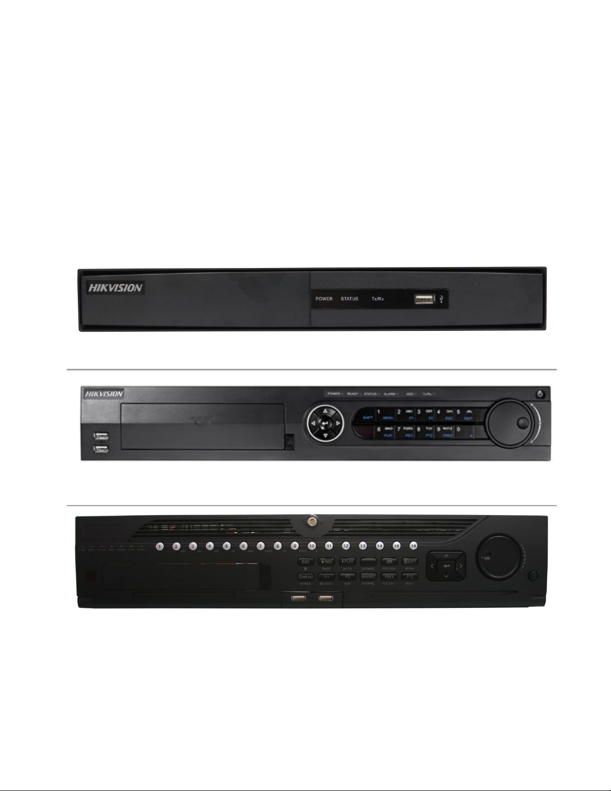
Figure 1 DS-7208/7216HGHI-SH DVR
Figure 2 DS-7308/7316HQHI-SH DVR
Figure 3 DS-9008/9016HQHI-SH DVR
8
Page 10

Product Features
General
Connectable to HD-TVI and analog cameras;
Connectable to the Coaxitron camera/dome with long transmission distance;
Connectable to IP cameras from Hikvision for HDVR series;
Each channel supports dual-stream. Main stream supports up to 1080P resolution and sub-
stream supports up to WD1 resolution;
Independent configuration for each channel, including resolution, frame rate, bit rate, image
quality, etc.
Encoding for both video stream and video & audio stream; audio and video synchronization
during composite stream encoding;
Watermark technology;
Local Monitoring
Simultaneous HDMI, VGA and CVBS outputs (no CVBS output for DS-7200 series);
HDMI output and VGA output at up to 1920*1080 resolution;
1/4/6/8/9/16 screen live view is supported, and the display sequence of screens is adjustable;
Live view screen can be switched in group and manual switch and automatic cycle live view
are also provided, the interval of automatic cycle can be adjusted;
Quick setting menu is provided for live view;
The selected live view channel can be shielded;
Motion detection, video-tampering detection, video exception alarm and video loss alarm
functions;
Privacy mask;
Several PTZ protocols supported; PTZ preset, patrol and pattern;
Zooming in/out by clicking the mouse and PTZ tracing by dragging mouse;
HDD Management
For DS-7200HGHI series, up to 2 SATA hard disks can be connected;
For DS-7300HQHI-SH series, 4 SATA hard disks and 1 eSATA disk can be connected;
For DS-9000HQHI-SH series, 8 SATA hard disks and 1 eSATA disk can be connected;
8 network disks (8 NAS disks, or 7 NAS disks+1 IP SAN disk) can be connected;
Support eSATA disks for recording or backup;
Support S.M.A.R.T. and bad sector detection;
Support HDD sleeping function;
HDD property: redundancy, read-only, read/write (R/W);
HDD group management;
HDD quota management; different capacity can be assigned to different channels;
9
Page 11

Recording and Playback
Holiday recording schedule configuration;
Cycle and non-cycle recording modes;
Normal and event video encoding parameters;
Multiple recording types: manual, continuous, alarm, motion, motion | alarm, motion & alarm;
8 recording time periods with separated recording types;
Pre-record and post-record for motion detection triggered recording, and pre-record time for
schedule and manual recording;
Searching record files by events (alarm input/motion detection);
Customization of tags, searching and playing back by tags;
Locking and unlocking of record files;
Local redundant recording;
Searching and playing back record files by camera number, recording type, start time, end
time, etc.;
Smart playback to go through less effective information;
Zooming in for any area when playback;
Reverse playback of multi-channel;
Supports pause, fast forward, slow forward, skip forward, and skip backward when playback,
locating by dragging the mouse on the progress bar;
Up to 16-ch synchronous playback at 1080P;
Backup
Export data by a USB, SATA or eSATA device;
Export video clips when playback;
Management and maintenance of backup devices;
Alarm and Exception
Configurable arming time of alarm input/output;
Alarm for video loss, motion detection, video tampering, abnormal signal, video
input/recording resolution mismatch, illegal login, network disconnected, IP confliction, record
exception, HDD error, and HDD full, etc.;
Alarm triggers full screen monitoring, audio alarm, notifying surveillance center, sending email
and alarm output;
Automatic restore when system is abnormal.
Other Local Functions
Manual and automatic video quality diagnostics;
Users can operate by mouse and remote control;
Three-level user management; admin user can create many operating account and define
their operating permission, which includes the permission to access any channel;
Completeness of operation, alarm, exceptions and log writing and searching;
10
Page 12

Manually triggering and clearing alarms;
Importing and exporting of configuration file of devices;
Getting cameras type information automatically.
Network Functions
1 self-adaptive 10M/100M network interface for DS-7204HGHI-SH; 1 self-adaptive
10M/100M/1000M network interface for other 7200/7300 series models; 2 self-adaptive
10M/100M/1000M network interface for 9000 series models;
IPv6 is supported;
TCP/IP protocol, PPPoE, DHCP, DNS, DDNS, NTP, SADP, SMTP, SNMP, NFS, iSCSI,
UPnP™ and HTTPS are supported;
Extranet access by HiDDNS.
Support access by EZVIZ Cloud P2P.
TCP, UDP and RTP for unicast;
Auto/Manual port mapping by UPnPTM
Remote search, playback, download, locking and unlocking the record files, and downloading
files broken transfer resume;
Remote parameters setup; remote import/export of device parameters;
Remote viewing of the device status, system logs and alarm status;
Remote keyboard operation;
Remote locking and unlocking of control panel and mouse;
Remote HDD formatting and program upgrading;
Remote system restart and shutdown;
Support upgrading via remote FTP server;
RS-232, RS-485 transparent channel transmission;
Alarm and exception information can be sent to the remote host;
Remotely start/stop recording;
Remotely start/stop alarm output;
Remote PTZ control;
Remote JPEG capture;
Two-way audio and voice broadcasting;
Embedded WEB server.
Development Scalability
SDK for Windows and Linux system;
Source code of application software for demo;
Development support and training for application system.
11
Page 13

Rear Panel
No. Item
Description
1
VIDEO IN
BNC connectors for video input.
2
AUDIO IN
RCA connector for audio input.
3
AUDIO OUT
RCA connector for audio output.
4
VGA
DB15 connector for VGA output. Display local video
output and menu.
5
HDMI
HDMI video output connector.
6
USB Interface
Connect to USB mouse or USB flash memory
devices.
7
LAN Interface
Connector for LAN (Local Area Network).
8
RS-485 Interface
Connector for RS-485 devices.
9
Power Supply
DC 12V power supply.
10
Power Switch
Switch for turning on/off the device.
11
GND
Ground
12
Alarm IN/OUT
Connectors for alarm inputs and alarm outputs.
Figure 4 DS-7208HGHI-SH
12
Page 14
Figure 5 DS-7316HQHI-SH
No.
Item
Description
1
VIDEO IN
BNC interface for TVI and analog video input.
2
VIDEO OUT
BNC connector for video output.
3
AUDIO IN
RCA connector
4
USB Port
Universal Serial Bus (USB) port for additional devices.
5
HDMI
HDMI video output connector.
6
VGA
DB15 connector for VGA output. Display local video
output and menu.
7
AUDIO OUT
RCA connector
8
Network Interface
Connector for network
9
RS-485 Interface
Connector for RS-485 devices. T+ and T- pins connect
to R+ and R- pins of PTZ receiver respectively.
D+, D- pin connects to Ta, Tb pin of controller. For
cascading devices, the first DVR’s D+, D- pin should be
connected with the D+, D- pin of the next DVR.
Connector for alarm input.
Connector for alarm output.
10
Power Supply
AC 100 ~ 240V power supply.
11
Power Switch
Switch for turning on/off the device.
12
GND
Ground
13
LINE IN
BNC connector for audio input.
13
Page 15

14
eSATA
Connects external SATA HDD, CD/DVD-RW.
15
RS-232 Interface
Connector for RS-232 devices.
14
Page 16
No.
Item
Description
1
VIDEO IN
BNC interface for TVI and analog video input.
2
VIDEO OUT
BNC connector for video output.
3
AUDIO IN
RCA connector
4
USB Port
Universal Serial Bus (USB) port for additional devices.
5
HDMI
HDMI video output connector.
6
VGA
DB15 connector for VGA output. Display local video
output and menu.
7
AUDIO OUT
RCA connector
8
Network Interface
Connector for network
9
RS-485 Interface
Connector for RS-485 devices. T+ and T- pins connect
to R+ and R- pins of PTZ receiver respectively.
D+, D- pin connects to Ta, Tb pin of controller. For
cascading devices, the first DVR’s D+, D- pin should be
connected with the D+, D- pin of the next DVR.
Connector for alarm input.
Connector for alarm output.
10
Power Supply
AC 100 ~ 240V power supply.
11
Power Switch
Switch for turning on/off the device.
12
GND
Ground
Figure 6 DS-9016HQHI-SH
15
Page 17

13
LINE IN
BNC connector for audio input.
14
eSATA
Connects external SATA HDD, CD/DVD-RW.
15
RS-232 Interface
Connector for RS-232 devices.
16
Page 18
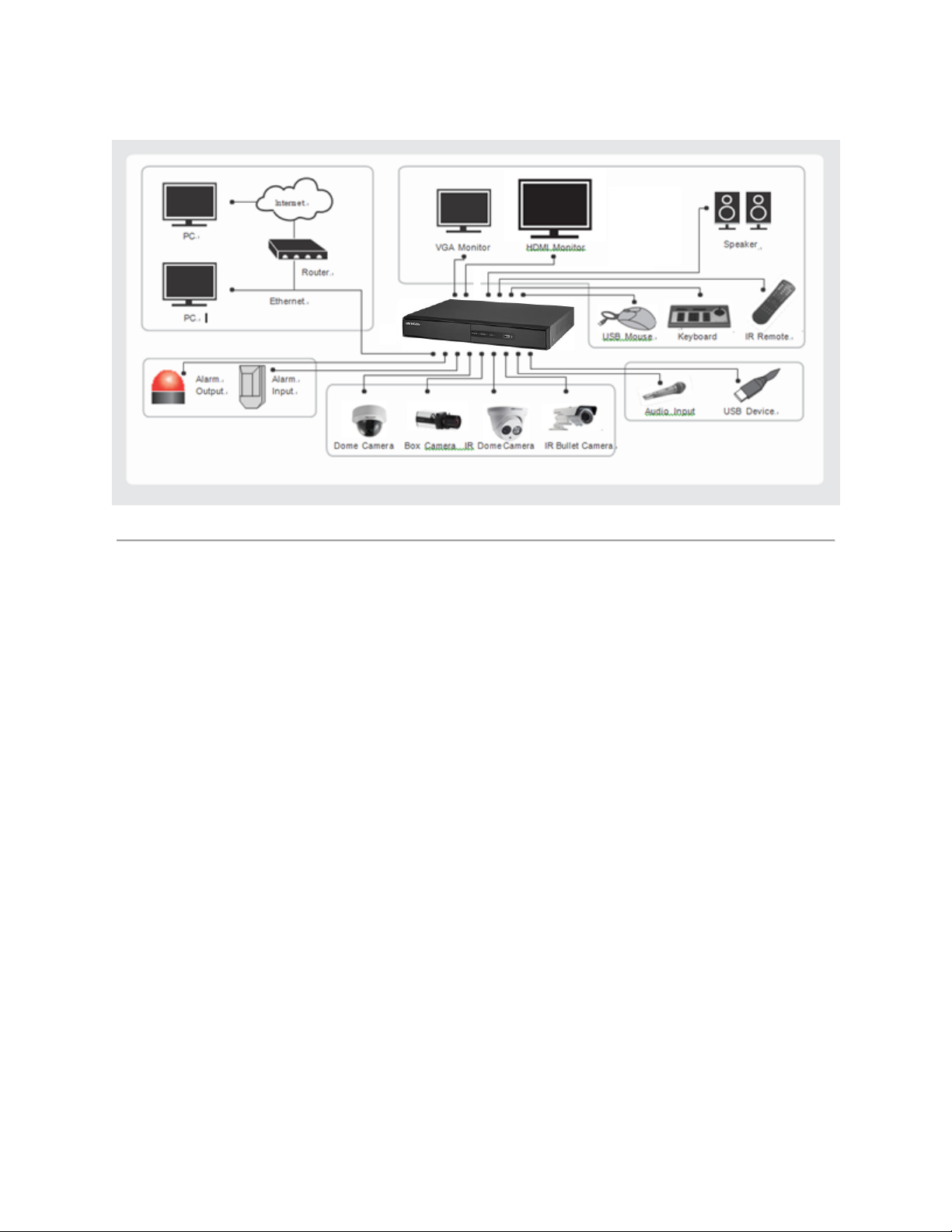
Product Application Diagram
Figure 7 Product Application Diagram
17
Page 19
Operating Your DVR
There are numerous ways to navigate and operate your DVR. You may use the Front Panel
Controls, the included IR (Infrared) Remote, a Mouse and the Soft Keyboard.
Using the Front Panel Controls
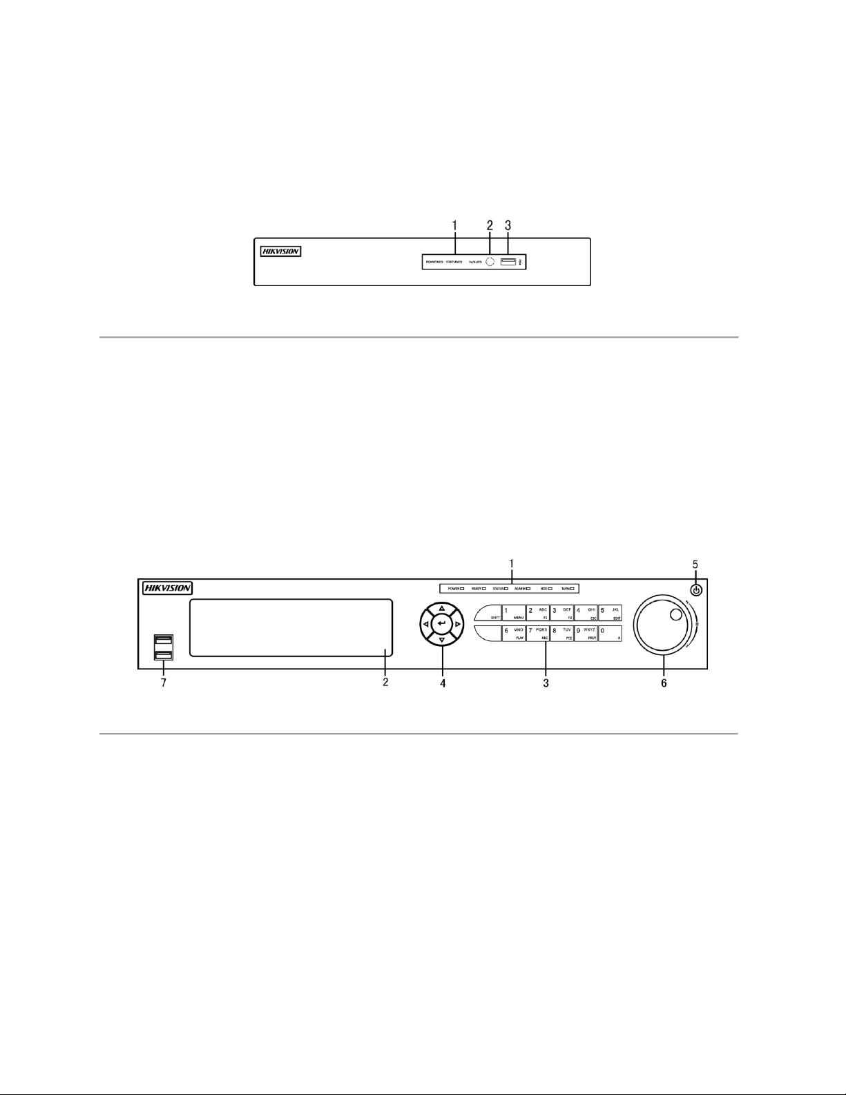
Your DVR comes with built-in front panel controls, as shown in the following figure:
Figure 8 7200HGHI-SH Panel Controls
The controls on the front panel include:
1. Status Indicators:
• Power: Power indicator turns green when the power switch on the real panel is
turned on.
• Status: Status indicator blinks red when data is being read from or written to HDD.
• TX/RX: Tx/Rx indictor blinks green when network connection is functioning properly.
2. IR Receiver: Receiver for IR remote.
3. USB Interfaces: Universal Serial Bus (USB) ports for additional devices such as USB
mouse and USB Hard Disk Drive (HDD).
Figure 9 7300HQHI-SH Panel Controls
The controls on the front panel include:
1. Status Indicators:
• Alarm: Alarm indicator turns red when a sensor alarm is detected.
• Ready: Ready indicator turns green when DVR is functioning properly.
• Status: Status indicator turns yellow when DVR is controlled by an IR remote.
Indicator turns red when controlled by a keyboard and purple when IR remote and
keyboard is used at the same time.
• HDD: HDD indicator blinks red when data is being read from or written to HDD.
• Power: Power indicator turns green when the power switch on the real panel is
turned on.
• TX/RX: TX/RX indictor blinks green when network connection is functioning properly.]
2. DVD-ROM: Slot for DVR-ROM.
18
Page 20

3. Alphanumeric/Control Buttons: Alphanumeric/Control buttons used in various menus of the
DVR. Alphanumeric-some uses include:
• Switching to the corresponding channel in Preview or PTZ Control mode.
• Inputting numbers and characters in Edit mode.
• Switching between different channels in Playback mode.
Control-some uses include:
• ESC Button: The ESC button is used to escape to the previous menu and to
arm/disarm the DVR in Preview mode.
• REC/SHOT Button: The REC/SHOT button is used to enter the Quick Schedule
Recording interface. If used when controlling a PTZ, pressing the REC/SHOT button
and then a Numeric button will call a PTZ preset.
• PLAY/AUTO Button: The PLAY/AUTO button is used to enter the Playback menu. It
is also used to turn audio on/off in the Playback menu and auto scan in the PTZ
Control menu.
• ZOOM+ Button: The ZOOM+ button is used to zoom the PTZ camera in when in the
PTZ Control menu.
• A/FOCUS+ Button: The A/FOCUS+ button is used to adjust focus in the PTZ
Control menu. It is also used to switch between input methods (upper and lowercase
alphabet, symbols and numeric input). It can also be used to clear entire masked
areas, such as in the Motion Detection and Privacy Mask menus.
• EDIT/IRIS+ Button: The EDIT/IRIS+ button is used to edit text fields. When editing
text fields, it will also function as a Backspace button to delete the character in front
of the cursor. On checkbox fields, pressing the EDIT/IRIS+ button will tick the
checkbox. In PTZ Control mode, the EDIT/IRIS+ button opens up the iris of the
camera. In Playback mode, it can be used to generate video clips for backup.
• MENU/WIPER Button: Pressing the MENU/WIPER button will return the user to the
Main menu (after successful login). Pressing and holding the button for 5 seconds
will turn off audible key beep. The MENU/WIPER button will also bring up Sensitivity
Interface settings. In PTZ Control mode, the MENU/WIPER button will start wiper (if
applicable).
• F1/LIGHT Button: The F1/LIGHT button when used in a list field will select all items
on the list. In PTZ Control mode, it will turn on/off PTZ light.
• F2/AUX Button: The F2/AUX button is used to cycle through tab pages. It will also
bring up the Channel & OSD Position settings.
• MAIN/SPOT/ZOOM- Button: The MAIN/SPOT/ZOOM- button is used to switch to
the control of spot output. In PTZ Control mode, it can be used to zoom the camera
out.
• PREV/FOCUS- Button: The PREV/FOCUS- button is used to switch between single
screen and multi-screen mode. In PTZ Control mode, it is used to adjust the focus in
conjunction with the A/FOCUS+ button. It can also be used to select entire masked
areas, such as in Motion Detection and Privacy Mask menus.
4. Direction/Enter Buttons:
• Direction Buttons: The Direction buttons are used to navigate between different
fields and items in menus. In playback mode, the Up and Down button is used to
fast-forward and rewind recorded video. The left and Right button will select the next
19
Page 21
and previous day of or pause the video. In Single Play mode, pressing the Enter
button will advance the video by a single frame.
• Enter Button: The Enter button is used to confirm selection in any of the menu
modes. It can be used to tick checkbox fields. In Playback mode, it can be used to
play or pause the video. In Single Play mode, pressing the Enter button will advance
the video by a single frame.
5. Power Button: Powers DVR on/off.
6. Jog Shuttle Control: The Jog Shuttle control can be used to move the active selection in a
menu. In the playback mode, the outer ring is used to speed up/slow down the video. The
inner ring can be used to jump 30 seconds forward/backward in a video. In Preview mode, it
can be used to cycle through different channels.
7. USB Ports: Connects USB mouse or USE flash memory devices.
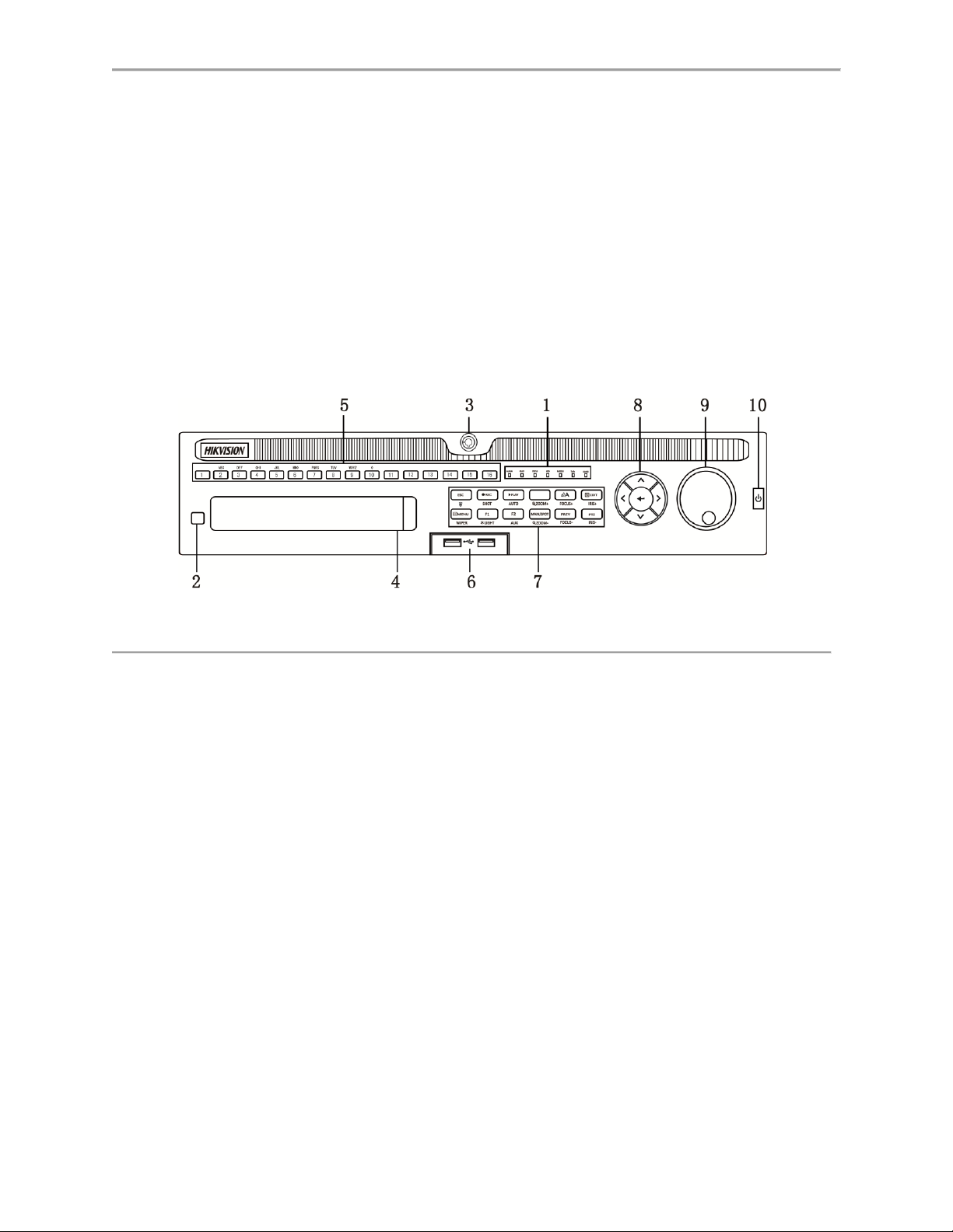
Figure 10 9000HQHI-SH Panel Controls
The controls on the front panel include:
1. Status Indicators:
• Alarm: Alarm indicator turns red when a sensor alarm is detected.
• Ready: Ready indicator turns green when DVR is functioning properly.
• Status: Status indicator turns yellow when DVR is controlled by an IR remote.
Indicator turns red when controlled by a keyboard and purple when IR remote and
keyboard is used at the same time.
• HDD: HDD indicator blinks red when data is being read from or written to HDD.
• Power: Power indicator turns green when the power switch on the real panel is
turned on.
• TX/RX: TX/RX indictor blinks green when network connection is functioning properly.
2. IR Receiver: Receiver for IR remote control.
3. Front Panel Lock: You can lock or unlock the panel by the key.
4. DVD-ROM: Slot for DVR-ROM.
5. Alphanumeric Buttons: Alphanumeric/Control buttons used in various menus of the DVR.
Alphanumeric-some uses include:
• Switching to the corresponding channel in Preview or PTZ Control mode.
• Inputting numbers and characters in Edit mode.
• Switching between different channels in Playback mode.
20
Page 22

6. USB Ports: Connects USB mouse or USE flash memory devices.
7. Control Buttons: some uses include:
• ESC Button: The ESC button is used to escape to the previous menu and to
arm/disarm the DVR in Preview mode.
• REC/SHOT Button: The REC/SHOT button is used to enter the Quick Schedule
Recording interface. If used when controlling a PTZ, pressing the REC/SHOT button
and then a Numeric button will call a PTZ preset.
• PLAY/AUTO Button: The PLAY/AUTO button is used to enter the Playback menu. It
is also used to turn audio on/off in the Playback menu and auto scan in the PTZ
Control menu.
• ZOOM+ Button: The ZOOM+ button is used to zoom the PTZ camera in when in the
PTZ Control menu.
• A/FOCUS+ Button: The A/FOCUS+ button is used to adjust focus in the PTZ
Control menu. It is also used to switch between input methods (upper and lowercase
alphabet, symbols and numeric input). It can also be used to clear entire masked
areas, such as in the Motion Detection and Privacy Mask menus.
• EDIT/IRIS+ Button: The EDIT/IRIS+ button is used to edit text fields. When editing
text fields, it will also function as a Backspace button to delete the character in front
of the cursor. On checkbox fields, pressing the EDIT/IRIS+ button will tick the
checkbox. In PTZ Control mode, the EDIT/IRIS+ button opens up the iris of the
camera. In Playback mode, it can be used to generate video clips for backup.
• MENU/WIPER Button: Pressing the MENU/WIPER button will return the user to the
Main menu (after successful login). Pressing and holding the button for 5 seconds
will turn off audible key beep. The MENU/WIPER button will also bring up Sensitivity
Interface settings. In PTZ Control mode, the MENU/WIPER button will start wiper (if
applicable).
• F1/LIGHT Button: The F1/LIGHT button when used in a list field will select all items
on the list. In PTZ Control mode, it will turn on/off PTZ light.
• F2/AUX Button: The F2/AUX button is used to cycle through tab pages. It will also
bring up the Channel & OSD Position settings.
• MAIN/SPOT/ZOOM- Button: The MAIN/SPOT/ZOOM- button is used to switch to
the control of spot output. In PTZ Control mode, it can be used to zoom the camera
out.
• PREV/FOCUS- Button: The PREV/FOCUS- button is used to switch between single
screen and multi-screen mode. In PTZ Control mode, it is used to adjust the focus in
conjunction with the A/FOCUS+ button. It can also be used to select entire masked
areas, such as in Motion Detection and Privacy Mask menus.
8. Direction/Enter Buttons:
• Direction Buttons: The Direction buttons are used to navigate between different
fields and items in menus. In playback mode, the Up and Down button is used to
fast-forward and rewind recorded video. The left and Right button will select the next
and previous day of or pause the video. In Single Play mode, pressing the Enter
button will advance the video by a single frame.
• Enter Button: The Enter button is used to confirm selection in any of the menu
modes. It can be used to tick checkbox fields. In Playback mode, it can be used to
21
Page 23
play or pause the video. In Single Play mode, pressing the Enter button will advance
the video by a single frame.
9. Jog Shuttle Control: The Jog Shuttle control can be used to move the active selection in a
menu. In the playback mode, the outer ring is used to speed up/slow down the video. The
inner ring can be used to jump 30 seconds forward/backward in a video. In Preview mode, it
can be used to cycle through different channels.
10. Power Button: Powers DVR on/off.
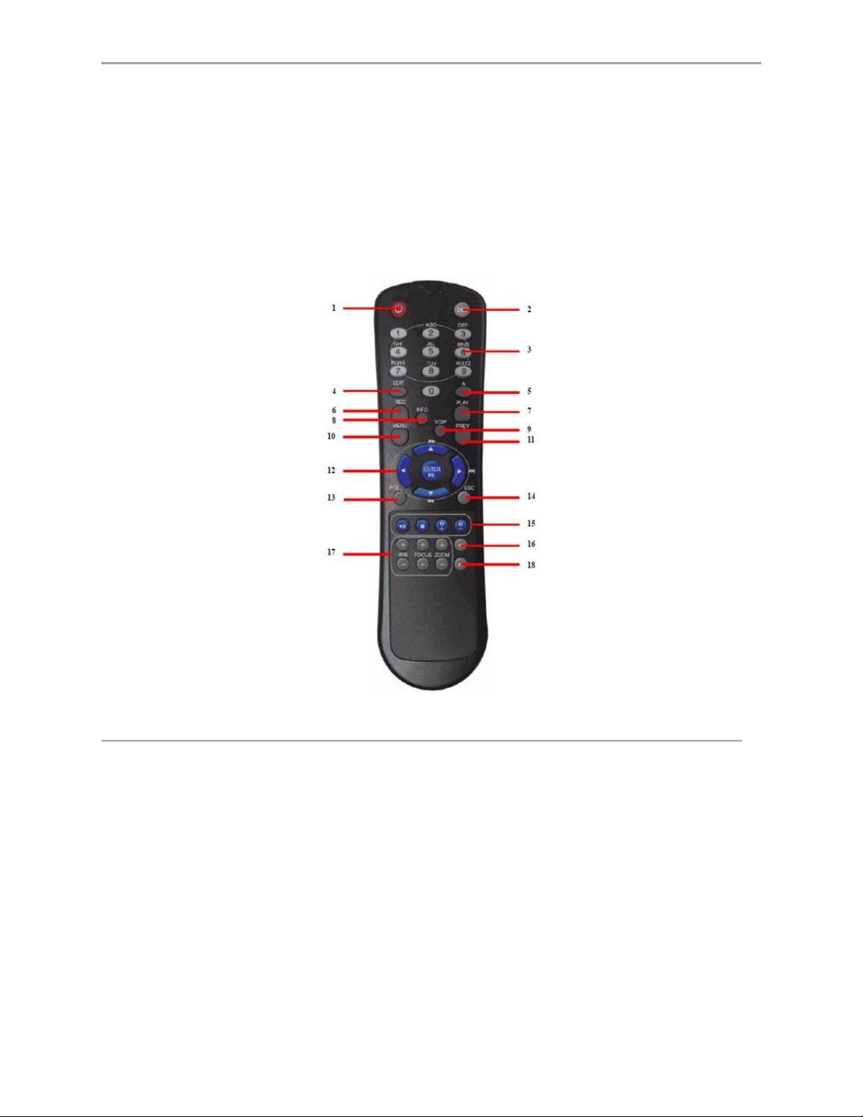
Figure 11 IR Remote Control
The keys on the remote control closely resemble the ones found on the front panel. Referring to
Figure 8, they include:
1. POWER: Turn on/off DVR.
2. DEV: Enable/Disable Remote Control.
3. Alphanumeric: Same as Alphanumeric buttons on front panel.
4. EDIT: Same as JKL/EDIT button on front panel.
5. A: Same as A/FOCUS+ button on front panel.
6. REC: Same as REC/SHOT button on front panel.
7. PLAY: Same as MNO/PLAY button on front panel.
8. INFO: Same as ZOOM+ button on front panel.
9. VOIP: Same as MAIN/SPOT/ZOOM- button on front panel.
10. MENU: Same as MENU/WIPER button on front panel.
11. PREV: Same as PREV/FOCUS- button on front panel.
22
Page 24

12. DIRECTION/ENTER Buttons: Same as DIRECTION/ENTER buttons on front
panel.
13. PTZ: Same as PTZ/IRIS- button on front panel.
14. ESC: Same as ESC button on front panel.
15. RESERVED: Reserved.
16. F1: Same as F1/LIGHT button on front panel.
17. PTZ CONTROL Buttons: Buttons to adjust the iris, focus and zoom of a PTZ
camera.
18. F2 Button: Same as F2/AUX button on front panel.
Aim the remote control at the IR receiver located at the front of the unit to test operation. If there
is no response:
1. Using the front control panel or the mouse, go into Menu > System Configuration >
General > More Settings.
2. Check and remember DVR ID#. The default ID# is 255. This ID# is valid for all IR
controls.
3. Press the DEV button on the remote.
4. Enter the DVR ID# from step 2.
5. Press the ENTER button on the remote control.
If the Status indicator on the front panel turns blue, the remote control is operating properly. If
the Status indicator does not turn blue and there is still no response from the remote, please
check the following:
1. Batteries are installed correctly and the polarities of the batteries are not reversed.
2. Batteries are fresh and not out of charge.
3. IR receiver is not obstructed.
4. No fluorescent lamp is used nearby.
Using a USB Mouse
A regular 3-button (Left/Right/Scroll-wheel) USB mouse can also be used with this DVR. To use
a USB mouse:
1. Plug USB mouse into one of the USB ports on the front panel of the DVR.
2. The mouse should automatically be detected. If in a rare case that the mouse is not
detected, please refer to the recommended device list from your provider.
The buttons on the mouse corresponds to:
1. Left Button:
• Single-Click: Select a component of a menu, such as a button or an input field. This
is similar to pressing the ENTER button on the remote/front panel controls.
• Double-Click: Switch between single screen and multi-screen mode in Preview/
Playback mode.
• Click and Drag: Clicking and dragging the Left mouse button can be used to control
the pan/tilt of a PTZ camera as well as to vary the position of digital zoom area and
camera OSD. It can also be used to set the alarm areas.
2. Right Button:
23
Page 25
• Single-Click: Shows pop-up menu in preview interface. Exit to return to the previous
menu.
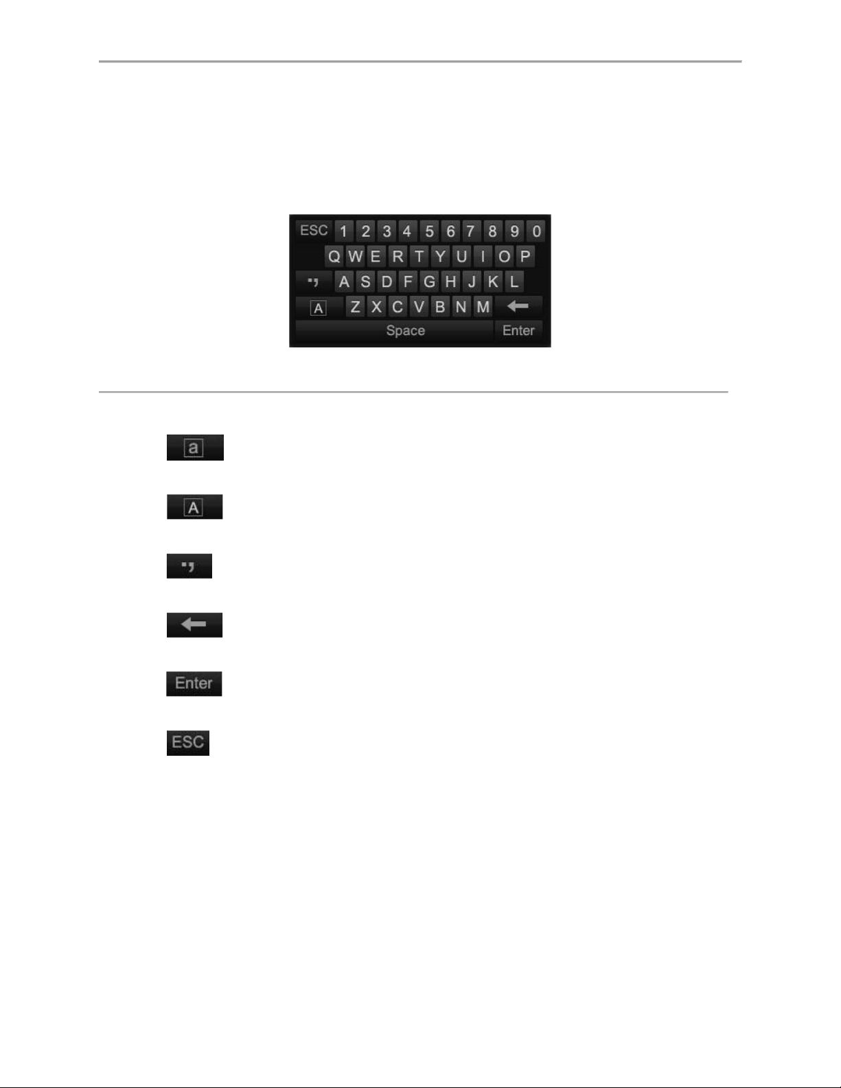
Using the Soft Keyboard
When a mouse is used to perform task on the DVR, clicking on a text input field will bring up the
Soft Keyboard, shown in Figure 9.
Figure 12 Soft Keyboard
The buttons on the soft keyboard represents:
Switch to Uppercase: Switch to uppercase input.
Switch to Lowercase: Switch to lowercase input.
Symbols: Switch to symbols input.
Backspace: Delete the character in front of the cursor.
Enter: Confirm selection.
ESC: Exit Soft Keyboard.
24
Page 26

Device Type
Model Number
Firmware Version
Value Series IP Camera
DS-2CD2xxx
V5.3.0
Smart Series IP Camera
DS-2CD4xxx
V5.3.0
NVR/Hybrid
DS-9016HWI-ST
DS-96xxNI-ST
DS-7716NI-SP/16
V3.1.5
Plug-n-Play NVR
DS-76xxNI-EI(E2)/P
V3.1.0
Turbo DVR
DS-72xxHGHI-SH
DS-73xxHQHI-SH
V3.1.6
Super NVR
DS-96128NI-E24/H
DS-96256NI-E24/H
TBD
C H A P T E R 2
Activating Your DVR
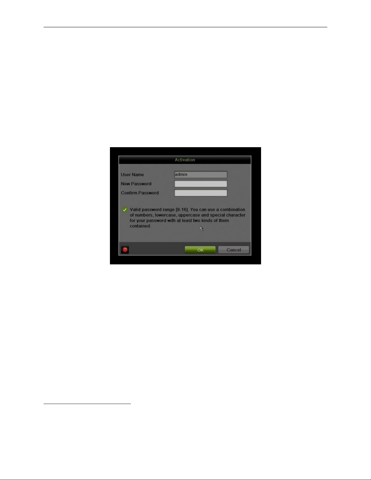
To ensure the highest level of protection, Hikvision has launched a login procedure that requires
users to create a new password for the admin account upon the first login to all devices. The
password must contain 8 to 16 characters, combining numbers, lowercase letters, uppercase
letters, and special characters. At least two types of the above-mentioned characters are
required to activate the device. The system will check the password strength; “Risky” passwords
will not be accepted.
Device Firmware with Secure Activation
NOTE: DVRs/NVRs starting with the latest firmware (see chart, above) WILL NO
• Local Activation
LONGER HAVE A DEFAULT PASSWORD. The user must activate the NVR by
creating a password for the admin account, which can be done in one of four
ways:
1. Power on the DVR/NVR.
- An activation message will appear on the screen prompting the user to
activate the device (Figure 13).
- The username field will be greyed-out with the username set to admin.
2. Type in a password of your choosing (see “Password Strength Levels” table on
page 37 for guidelines).
25
Page 27
- The password strength will be displayed, accompanied by a color
indicator:
• Level 0–Risky (red indicator): Not acceptable
• Level 1–Weak (red indicator): Acceptable
• Level 2–Fair (orange indicator): Acceptable
• Level 3–Strong (blue indicator): Acceptable
- Activation will not be allowed unless the password is of acceptable
strength (Figures 14, 15, and 16).
3. Retype the password into the “Confirm Password” field.
Figure 13 Activation Window
NOTE: The strength level indicator colors can vary by activation process, model number,
and device type.
26
Page 28
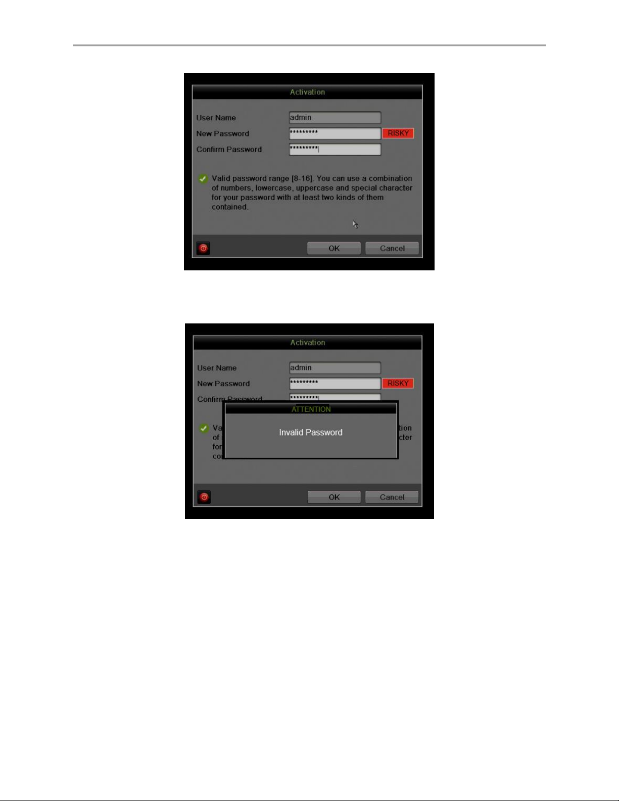
Figure 14 Risky (Inadequate) Strength Password
Figure 15 Invalid Password Message
27
Page 29
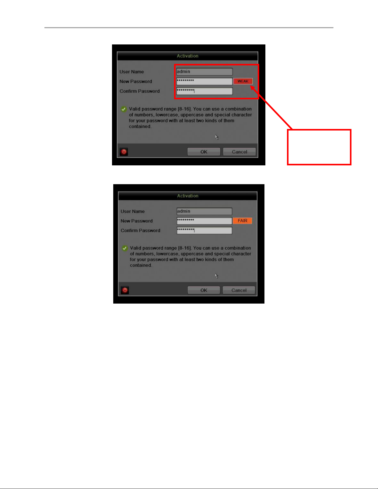
Figure 16 Weak (Adequate) Password Strength
NOTE: The
password strength
is shown with a
color indicator
Figure 17 Fair (Adequate) Password Strength
28
Page 30
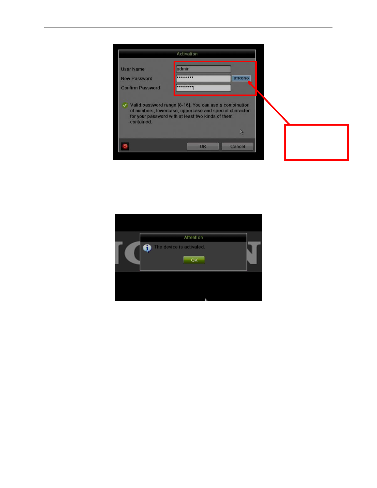
Figure 18 Strong Password Strength
NOTE: The
password strength
is shown with a
color indicator
3. After an acceptable password has been created, a confirmation message will
appear on the screen (Figure 19).
4. Press the OK button to proceed.
Figure 19 Activation Confirmation Message
• SADP Software Activation (v2.2.3.5 or higher)
1. Launch the new version of the SADP software (v2.2.3.5).
- The software will display all Hikvision devices on the network.
- A new field called “Security” will display whether the DVR/NVR is
active or not (Figure 20).
2. If the DVR/NVR is “Inactive,” highlight the DVR/NVR and enter a new password
into the “New Password” field on the bottom right of the screen (Figure 20). See
“Password Strength Levels” table on page 37 for guidelines.
- The password strength will be displayed, accompanied by a color
indicator:
29
Page 31

• Level 0–Risky (no indicator): Not acceptable
• Level 1–Weak (pink indicator): Acceptable
• Level 2–Medium (yellow indicator): Acceptable
• Level 3–Strong (green indicator): Acceptable
- Bar length indicates strength level.
- Activation will not be allowed unless the password is of acceptable
strength (Figures 23, 24, and 25). If the password is unacceptable
strength (“Risky,” Figure 21), a warning box will be displayed (Figure
22).
3. Retype the password into the “Confirm Password” field.
4. After the password has been entered and confirmed, press the OK button to
display the pop-up confirmation window (Figure 26).
5. Press the “X” in the top right corner of the pop-up confirmation window to dismiss
the window.
Figure 20 Security Field
30
Page 32
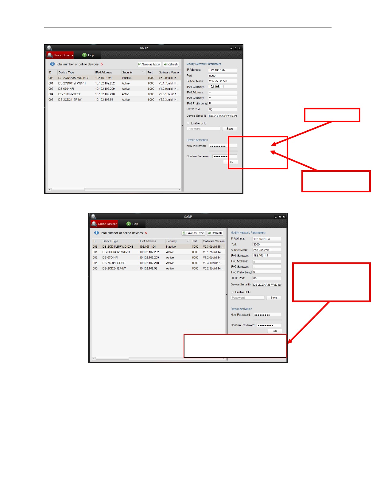
Figure 21 Password Field with “Risky” Unacceptable Password
Risky Password
The “Strength Meter”
does not light up
A message indicates
that the password has
to meet minimum
requirements
Valid password range [8-16]. You can use a combination
of numbers, lowercase, uppercase and special
characters for your password with at least two kinds of
them contained.
Figure 22 “Risky” Unacceptable Password Warning Message
31
Page 33
Figure 23 Password Field with Weak Strength Password
NOTE: The
password strength
is shown with a
color indicator.
Figure 24 Password Field with Medium Strength Password
32
Page 34
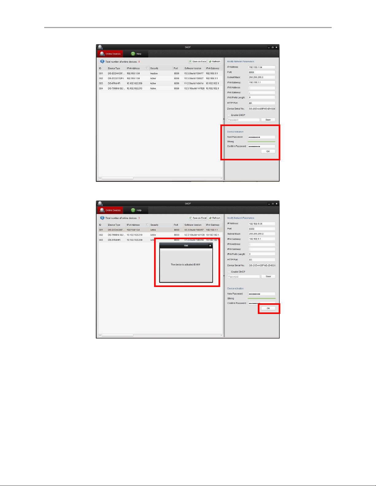
Figure 25 Password Field with Strong Strength Bar
Figure 26 Confirmation Window
33
Page 35

• iVMS-4200 Windows Client Software (v2.3.1.3 or higher) Activation
1. Launch the iVMS-4200 software.
2. Go to Control PanelDevice Management (Figure 27).
- On the bottom of the screen in the Online Devices section the screen
will display all Hikvision devices on the network.
- A new field called “Security” will display whether the DVR/NVR is
active or not (Figure 28).
3. If the DVR/NVR is “Inactive,” highlight the DVR/NVR and press the Activate
button (Figure 28) to display the “Activation” window (Figure 29).
4. Enter a new password into the “Password” field (Figure 29). See “Password
Strength Levels” table on page 37 for guidelines.
- The password strength will be displayed, accompanied by a color
indicator:
• Level 0–Risky (no indicator): Not acceptable
• Level 1–Weak (pink indicator): Acceptable
• Level 2–Medium (yellow indicator): Acceptable
• Level 3–Strong (green indicator): Acceptable
- Bar length indicates strength level.
- Activation will be allowed if the password is of acceptable strength
(Figures 31, 32, and 33).
- If the password is of unacceptable strength (“Risky,” Figure 29), a
warning box will be displayed (Figure 30) explaining the requirements
for an acceptable password.
5. Retype the password into the “Confirm Password” field.
6. After the password has been entered and confirmed, press the OK button.
- The DVR’s/NVR’s status will change to “Active” (Figure 31).
34
Page 36

Figure 27 iVMS 4200 Control Panel
NVR Status:
Inactive
Figure 28 Inactive DVR/NVR Status
35
Page 37

Figure 29 Activation Window with Risky (Inadequate) Password Strength
Risky Password
The “Strength Meter”
does not light up
A message indicates
that the password has
to meet minimum
requirements
Valid password range [8-16]. You can use a combination of
numbers, lowercase, uppercase and special characters for your
password with at least two kinds of them contained.
Figure 30 Risky (Inadequate) Password Strength Warning Message
36
Page 38

Figure 31 Weak (Adequate) Password Strength
Figure 32 Medium (Adequate) Password Strengt
37
Page 39
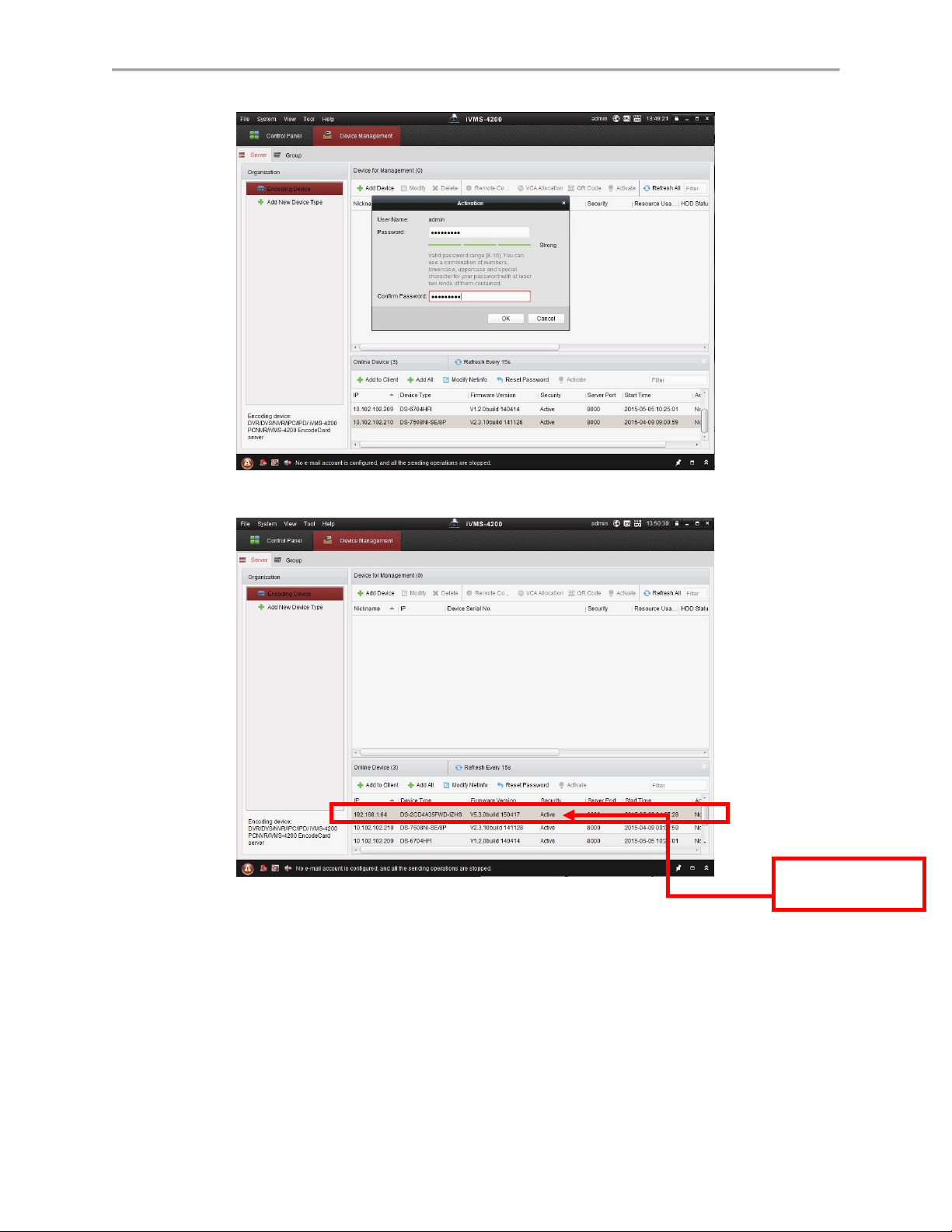
Figure 33 Strong (Adequate) Password Strength
NVR Status:
Active
Figure 34 Active DVR/NVR Status
38
Page 40

• Web Interface Activation (use if the SADP or iVMS-4200 software do not
support the activation procedure).
1. In a Web browser (i.e., Internet Explorer, Chrome, Safari), type the DVR’s/NVR’s
IP address and press Enter.
- The Activation Window will appear instead of the login page (Figure
35).
2. Enter a new password into the “Password” field (see “Password Strength Levels”
table on page 38 for guidelines).
- The password strength will be displayed, accompanied by a color
indicator:
• Level 0–Risky (no indicator): Not acceptable
• Level 1–Weak (pink indicator): Acceptable
• Level 2–Medium (yellow indicator): Acceptable
• Level 3–Strong (green indicator): Acceptable
- Bar length indicates strength level (Figure 36).
- Activation will be allowed if the password is of acceptable strength
(Figures 38, 39, 40). A white checkmark will appear in a green circle to
the right of the password field.
- If the password is unacceptable strength (“Risky,” Figure 36), a white
X will appear in a red circle to the right of the password field and a
warning dialog box will be displayed (Figure 37) explaining the
requirements for an acceptable password.
3. Press the OK button.
- After a successful activation the user will be logged in to the
DVR’s/NVR’s live view page.
39
Page 41
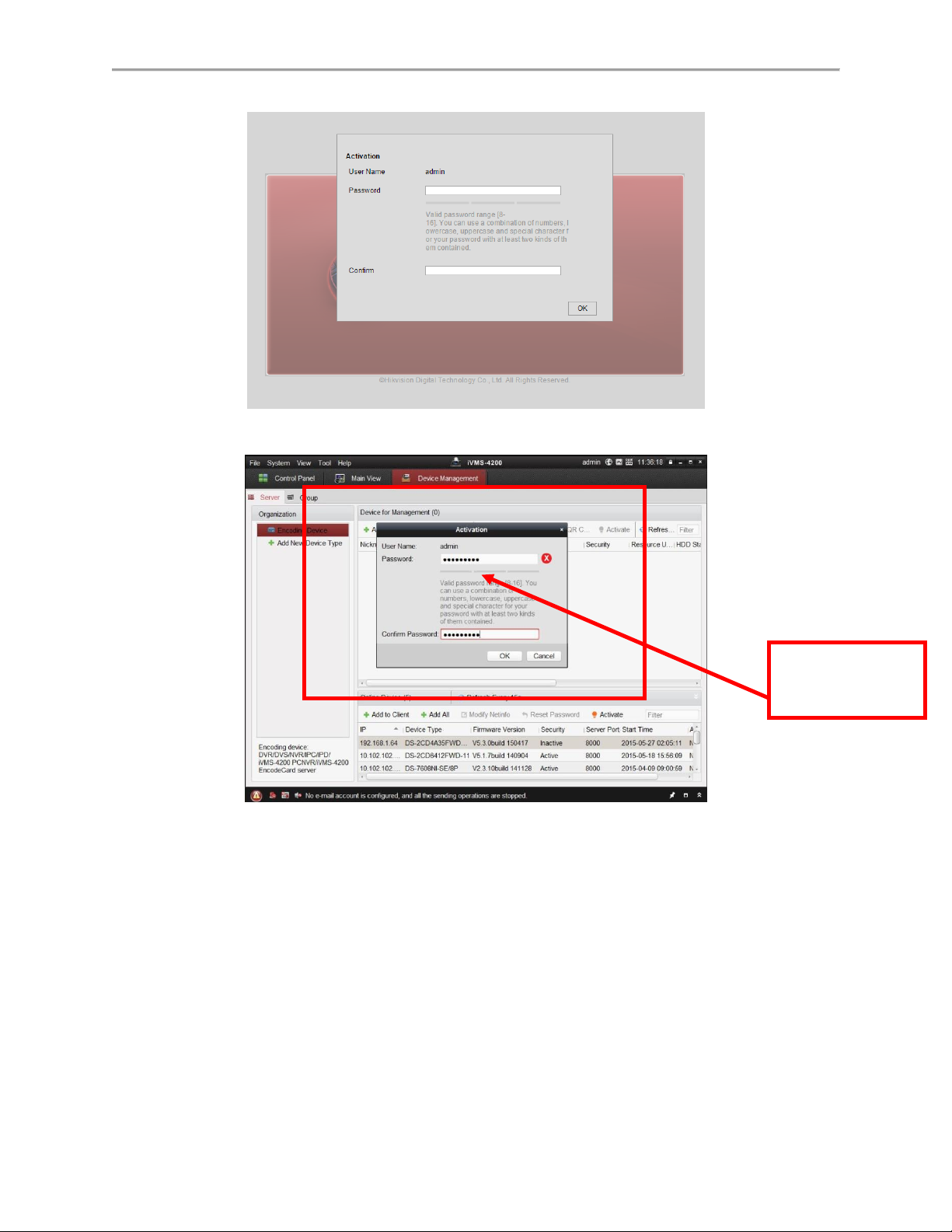
Figure 35 Activation Window
The “Strength
Meter” does not
light up
Figure 36 Risky (Inadequate) Password Strength
40
Page 42

Figure 37 Risky (Inadequate) Password Warning Window
Valid password range [8-16]. You can use a combination of
numbers, lowercase, uppercase and special characters for your
password with at least two kinds of them contained.
A message indicates
that the password has
to meet minimum
requirements
Figure 38 Weak (Acceptable) Strength Password
41
Page 43

Figure 39 Medium (Acceptable) Strength Password
Figure 40 Strong (Acceptable) Strength Password
42
Page 44

Password Strength Levels
STRENGTH LEVEL
DESCRIPTION
Level 0 (Risky)
NVRs will not accept a Level 0 password
Password length is fewer than eight characters,
contains only one type of character, is the same
as the user name, and/or is the mirror writing of
the user name. This type of password will not be
accepted.
Level 1 (Weak)
NVRs will accept a Level 1 password
Password contains two kinds of characters. The
combination is number + lowercase letter or
number + uppercase letter, and the password
length is at least eight characters. This type of
password will be accepted.
Level 2 (Medium/Fair)
NVRs will accept a Level 2 password
Password contains two types of characters. The
combination is neither number + lowercase letter
nor number + uppercase letter, and the password
length is at least eight characters. This type of
password will be accepted.
Level 3 (Strong)
NVRs will accept a Level 3 password
Password contains more than three types of
characters, and the password length is at least
eight characters. This type of password will be
accepted.
NOTE: Types of characters are lowercase letters, uppercase letters,
numbers, and special characters. Only ASCII characters are
allowed.
NOTE: The strength level indicator colors can vary by activation process, model number,
and device type.
43
Page 45

C H A P T E R 3
Getting Started
Starting and Shutting Down Your DVR
Proper startup and shutdown procedures are crucial to expanding the life of your DVR.
Startup Your DVR
Ensure the power supply is plugged into an electrical outlet. It is HIGHLY recommended
that an Uninterruptible Power Supply (UPS) be used in conjunction with the unit. The Power
indicator LED on the front panel should turn red, indicating the unit is receiving power.
Connect the DVR to a VGA monitor. You will only see the DVR menu system when it’s
connected to a VGA monitor.
Press the POWER switch on the back rear panel. The Power indicator LED should turn
green. The unit will begin to start.
After startup, the Power indicator LED will remain green. A splash screen with the status of
the HDD will be shown (Figure 41). If an ‘X’ is shown, it means that the HDD is not installed
or cannot be detected.
Figure 41 Startup Splash Screen
Shutdown Your DVR
There are two proper ways to shut down your DVR. To shut down your DVR:
Option 1:
1. Press and hold the POWER button on the front panel for 3 seconds.
2. Enter the administrator’s username and password in the dialog box for authentication.
3. There will pop-up an attention box.
4. Click the Yes button to shut down your DVR and click the No button to cancel.
Option 2:
44
Page 46

1. Shutdown your DVR by going to Menu > Maintenance, click in the lower left corner
to pop-up the Shutdown menu, as shown in Figure 42.
Figure 42 Shutdown Menu
2. Select the Shutdown button.
3. Click the Yes button.
Note:
Do not press the POWER button again when the system is shutting down.
Rebooting Your DVR
While in the Shutdown menu (Figure 42), you may also reboot your DVR by clicking Reboot.
Locking Your DVR
Locking your DVR will return you to the Live Feed mode, which will require the correct user
name and password to exit out of it and do operation. You have two methods to lock your DVR.
Enter the Shutdown menu by going to Menu > Maintenance > Shutdown, and click
the Lock button.
Click on the lower left corner of Menu interface to lock your DVR.
Note:
You can also set auto lock time to lock the menu for a certain period of time inactivity. Enable
auto locking by going to Menu > System Configuration > General > More Setting, and select
auto lock time in the auto lock time drop down list.
45
Page 47

Setting Date and Time
It is extremely important to setup the system date and time to accurately timestamp recordings
and events.
Set up date and time as follows:
1. Enter the System Configuration menu by going to Menu > System Configuration >
General.
2. Select the Time/Date tab, as shown in Figure 43.
Figure 43 System Configuration Menu
3. The current system time and date as well as the time zone will be displayed. Using the
directional buttons on the front panel/remote or the mouse, select the correct date, time
and time zone.
4. To enable Daylight Savings Time, click and check the Enable DST checkbox and there
will pop-up the DST Setting menu, as shown in Figure 44. You can check the Auto DST
Adjusting checkbox or manually check the date of the DST period and click the Apply
button to confirm the setting. Click the OK button to return to the up level menu.
46
Page 48

Figure 44 DST Settings Menu
5. To acquire the time and date over an NTP (Network Time Protocol) Server, check the
Enable NTP checkbox. You can set the interval and enter your own NTP server.
6. Click the Apply button to save the settings and click to exit out of the menu.
Clicking without clicking the Apply button will exit the menu without saving.
Checking the Status of Your DVR
The current status of your DVR can be checked at any time by going to the System Information
menu. The System Information menu, as shown in Figure 45, can be accessed by going to
Menu > System Information.
47
Page 49
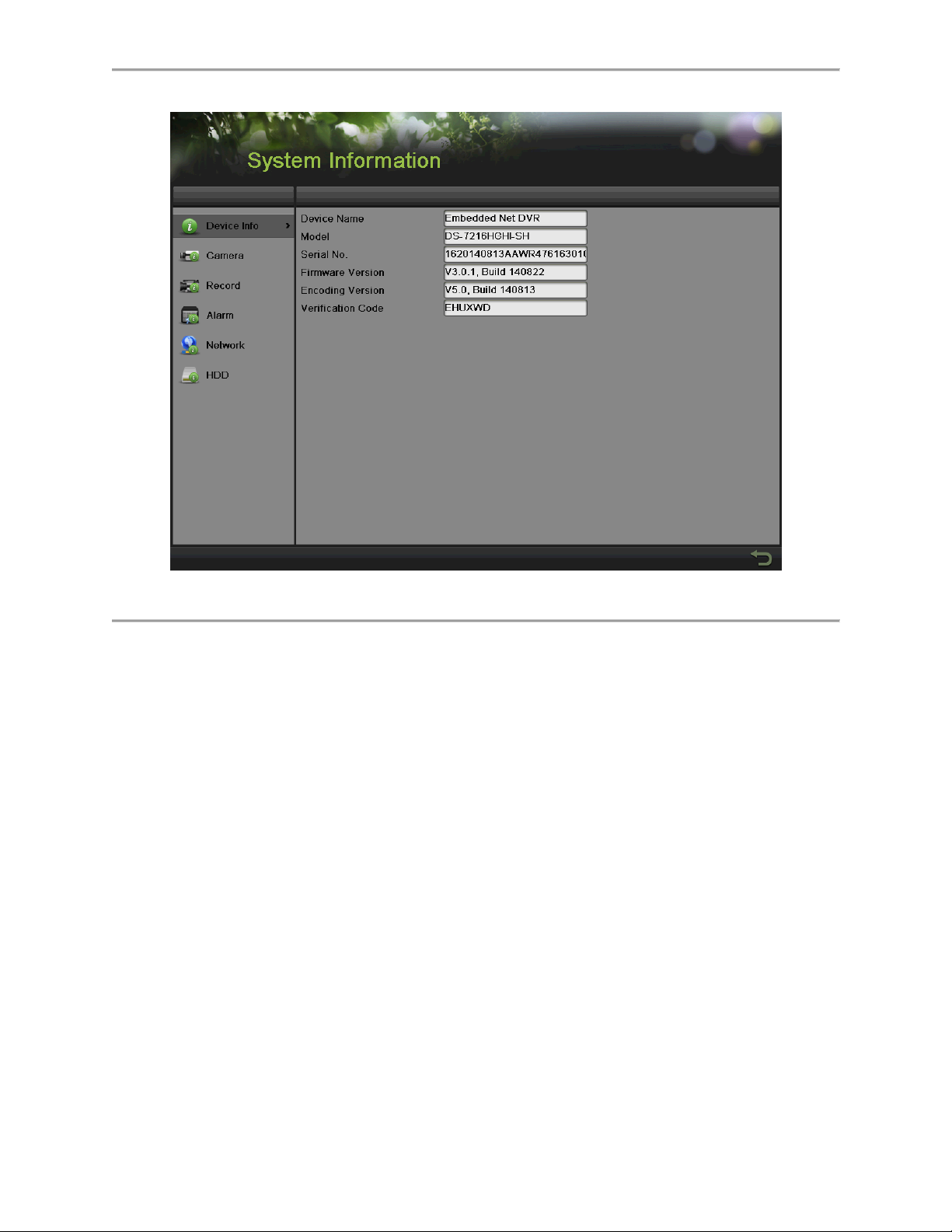
Figure 45 System Information Menu
1. Select the Device Info tab to enter the Device Information menu to view the device name,
model, serial No., firmware version and encode version, as shown in Figure 45.
2. Select the Camera tab to enter the Camera Information menu to view the status of each
camera, as shown in Figure 46.
48
Page 50
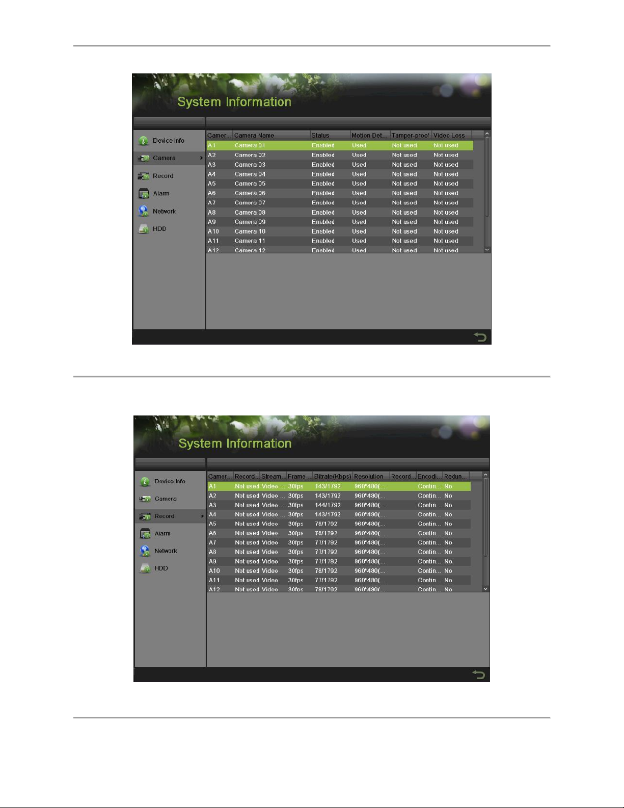
Figure 46 Camera Information Menu
3. Select the Record tab to enter the Record Information menu to view the recording status
and encoding parameters of each camera, as shown in Figure 47.
Figure 47 Record Information Menu
49
Page 51
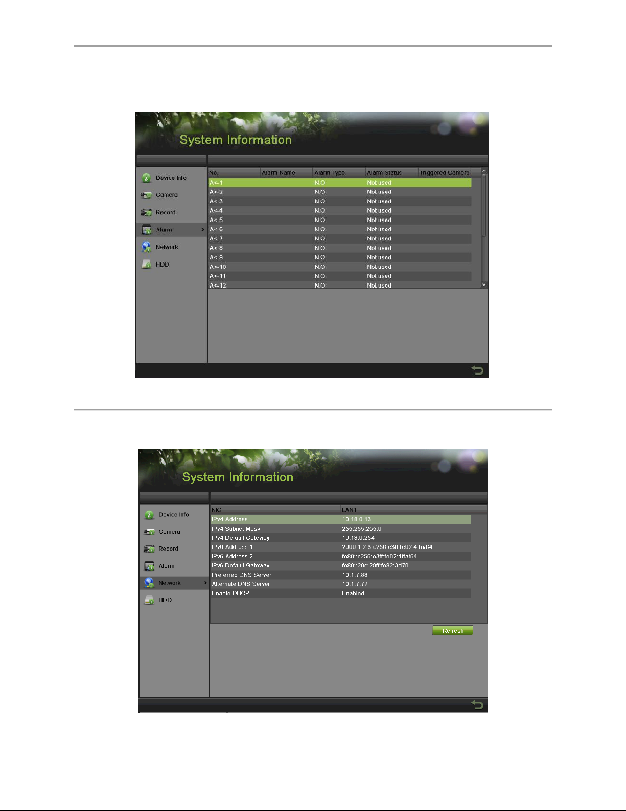
4. Select the Alarm tab to enter the Alarm Information menu to view the alarm information,
as shown in Figure 48.
Figure 48 Alarm Information Menu
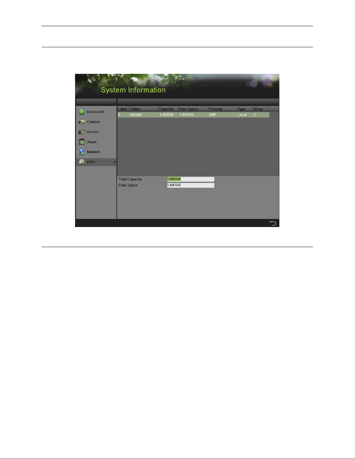
5. Select the Network tab to enter the Network Information menu to view the network
information, as shown in Figure 49.
Figure 49 Network Information Menu
50
Page 52
6. Select the HDD tab to enter the HDD Information menu to view the HDD status, free
space, capacity, etc., as shown in Figure 50.
Figure 50 HDD Information Menu
51
Page 53

C H A P T E R 4
Live Feed
Watching a Live Feed
The Live Feed mode is automatically started after the DVR boots up. It is also at the very top of
the menu hierarchy, thus hitting the ESC button multiple times (depending on which menu
you’re on) will bring you to the Live Feed mode.
Understanding Live Feed Icons
There are multiple icons on each display in Live Feed mode to indicate different camera status
and settings. These icons include:
Event Icon: Indicates video loss or tampering, motion detection and/or sensor alarm.
Record Icon: Indicates the current channel is recording. The recording may have been
started from a schedule, and/or triggered from motion or alarm.
Manual Record Icon: Enable/disable manual record.
Instant Playback Icon: Instant playback the record in last five minutes.
Audio On/Audio Off Icon: Enable/disable audio for selected display.
Capture Icon: Capture images for the selected display.
PTZ Control Icon: Enable PTZ control mode for the selected display.
Digital Zoom Icon: Zoom in the selected area to the full screen.
Image Settings Icon: Enter the image setting menu for selected display.
Close Icon: Exit out of current setting and return to previous mode.
Note:
Status for video loss is only valid with analog cameras. Event icons will only be displayed when
armed, except for the video loss alarm.
Operating the Live Feed
In Live Feed mode, you may adjust the settings for individual cameras by left-clicking on the
desired display with the mouse. The selected display will be surrounded with a green border, as
shown in Figure 51.
52
Page 54
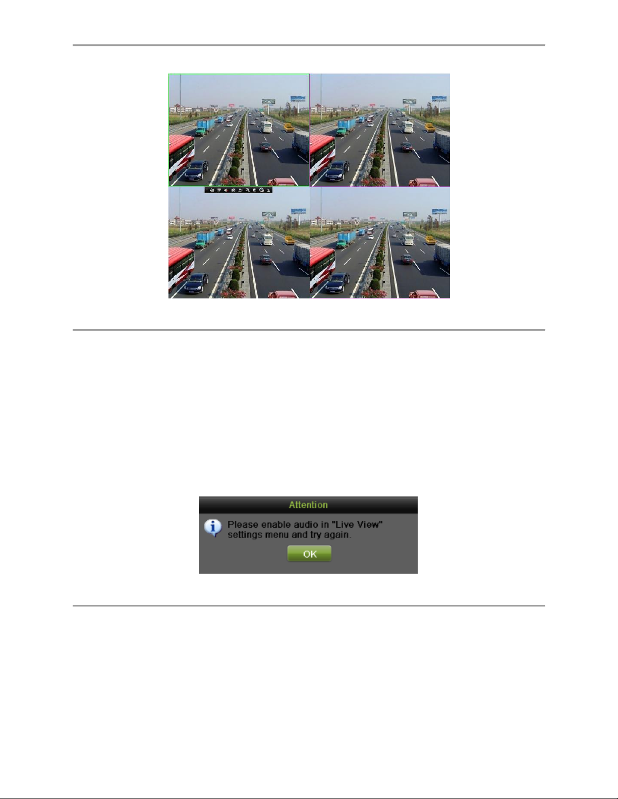
Figure 51 Live Feed Mode
The settings you may adjust with each display include:
Manual Record:
Enable/disable manual record by clicking the icon for a selected display.
Instant Playback:
Click the Instant playback icon to show the record in last five minutes. If no record is found, it
means there is no record during the last five minutes
Audio:
Enable/disable audio for a selected display. To enable/disable audio:
1. Select one display to enable/disable audio.
2. Enable audio by clicking the Enable Audio icon and disable audio by clicking the Disable
Audio icon. An error message similar to the one shown in Figure 52 will pop-up if the
Enable Audio option is not selected in the Live View menu for the specified channel.
Figure 52 Enable Audio Attention Message
Capture:
Do capture by clicking the icon for a selected display.
PTZ Control:
If the selected camera is a PTZ camera, you may control it directly from the display. Control a
PTZ camera as following steps:
1. Select the display that corresponds to a PTZ camera.
53
Page 55
2. Click the PTZ Control icon. This will bring up additional PTZ control buttons, as shown in
Figure 53.
Figure 53 PTZ Control Mode
3. Control the PTZ by using PTZ control buttons. Pan and tilt PTZ by clicking on the
directional buttons. Zoom in and out using the Zoom In/Out buttons and recall presets,
patrols and patterns by clicking the corresponding icons.
4.
Below is the description of the PTZ control icons:
Direction buttons and the auto-cycle button
Zoom+/Zoom-
Focus+/Focus-
Iris+/Iris-
The speed of the PTZ movement
Light On/Off
Wiper On/Off
3D-Zoom
Image Centralization
54
Page 56

Menu
5. Click the Close icon to return to the Live Feed mode.
Note:
PTZ parameters for the camera must be set correctly before the PTZ can be controlled.
Digital Zoom Mode:
Enable digital zoom on the selected channel. Once enabled, the regular feed will be shown in
the lower right corner while the zoomed in view will be shown on the full screen. The zoomed in
region may be changed by moving the red rectangle in the regular feed window, as shown in the
Figure 54. Right click to back to the Live Feed mode.
Figure 54 Digital Zoom
Image Settings:
Set the image mode and image parameters like brightness, contrast, saturation, hue and so on
for selected display. To adjust the image settings of a display as following steps:
1. Select display.
2. Click the Image Settings icon. This will bring up the Image Settings menu, analog
camera is shown in Figure 55.
55
Page 57

Figure 55 Analog Camera Image Settings Menu
3. For analog camera, there are four preset modes for selection: Standard, Indoor, Dim
Light and Outdoor. You can select one according to the real situation.
4. You can also adjust the image parameters like Brightness , Contrast , Saturation
, Hue by dragging the corresponding icon. The effect will be displayed
immediately on the screen.
Click Default will restore the default settings.
If the same settings can be applied in other channels, click the Copy button to pop-
up a Copy to box and check the corresponding checkbox. Click the OK button to
save and back to Image Setting menu. Click Cancel to exit without saving.
Click OK to save the settings and return to the Live Feed mode.
5. For IP camera, only Customize is supported. You can adjust the Brightness, Contrast,
Saturation and Hue by dragging the corresponding icon. Click the OK button to save the
settings and back to the Live Feed mode.
You can also enter the Image setting menu by going to Menu > Cameras Setup > Image, as
shown in Figure 56. The steps are similar to the live feed icon setting steps. If the same settings
can be applied in other channels, click the Copy button to copy it to other channels.
Figure 56 Image Settings Menu
56
Page 58

Using Display Menu
The Display Menu can be accessed by right-clicking the mouse on any of the display in Live
Feed mode. The Display Menu, as shown in Figure 57, allows you to quickly change into
different display modes and to start/stop auto-switching of the display modes.
Figure 57 Live Feed Display Menu
Menu: Click to go to DVR Main Menu. If the system is locked, you must enter the current admin
password to exit out of the Live Feed.
57
Page 59

Single Screen/Multi-Screen: Click to switch the display mode.
Previous Screen/Next Screen: Click to view the previous/next set of display. In a 2x2 mode,
this will show the next four display. In a 3x3 mode, this will show the next nine display.
Start/Stop Auto-Switch: Click to start/ stop auto-switch. Auto-switch will cycle through selected
cameras. Switching of camera can be based on an individual or multiple cameras.
Start Recording: Click the Continues Record/Event Record item. This will bring up an attention
box shown below. If you click yes, it will start all-day continues/event recording of all channels.
Note:
1. Before you start Auto-switch, you should set Dwell Time in Live View setting menu by
going to Menu > System Configuration > Live View > General.
2. After 20 seconds of inactivity, the DVR will automatically exit out of the Display menu
and go back into the Live Feed mode.
3. The auto lock menu setting is selected by default, meaning the Admin password must
be enter to exit out of the Live Feed into the Main Menu.
Configuring Live Feed Displays
Live Feed displays can be customized to your own needs.
To customize display settings:
1. Set language, CVBS output standard, resolution and so on by going to Menu > System
Configuration > General > Display, as shown in Figure 58.
58
Page 60

Figure 58 Display Menu
The settings available to configure in this menu include:
Language: The default language used is English.
Resolution: Select the appropriate resolution of VGA/HDMI output.
Mouse Pointer Speed: Set the speed of mouse pointer and 4 levels are
configurable.
Double Click Speed: Set the speed of mouse double click and 3 levels are
configurable.
Enable Password: Check the checkbox to enable the live view password.
Enable HDMI Resolution Auto: Check the checkbox to enable auto adjust HDMI
resolution.
2. Set device name, device no., CVBS output brightness, auto lock time and menu output
mode by going to Menu > System Configuration > General > More Settings, as shown in
Figure 59.
Figure 59 More Settings Menu
The settings available to configure in this menu include:
Device Name: Edit the name of the device.
Device No.: Edit the number of the device.
Auto Locktime: Set the auto lock time of menu.
Menu Output Mode: select the menu output mode from Auto, HDMI, VGA and Main
CVBS.
3. Set the live view interface parameters and event output by going to Menu > System
Configuration > Live View > General, as shown in Figure 60.
59
Page 61

Figure 60 Live View Menu
The settings available to configure for each video output include:
Video Output Interface: Designates the output including Main CVBS, HDMI, VGA.
Live View Mode: Designates the display mode for Live Preview.
Dwell Time: Set the time to dwell between switching of channels when Start Auto-
switch is selected in Live Preview.
Enable Audio Output: Enable or disable audio output for the selected video output.
Event Output: Designates the output to show event video.
Full Screen Monitoring Dwell Time: Set the time to dwell between switching of
channels when events occur.
Setting Camera Order
Setting the camera order allows you to logically position cameras for more efficient monitoring of
your own individual location.
Figure 61 Camera Order Settings Menu
To set the camera order:
60
Page 62

1. Enter the Live View menu, shown in Figure 61 by going to Menu > System
Configuration > Live View.
2. Select the View tab.
3. Select the Video Output Interface to configure camera order for.
4. Select the Screen Configuration you would like to use in Live Feed by clicking
. The preview of the screen configuration on the right will change
depending on the option selected.
5. Click to select a screen in the right region and double-click to select a channel in the left
region. Thus the selected channel will be displayed in the corresponding screen.
Note:
means no channel will be displayed in this screen.
6. Click to start live view of all channels and click to stop live view all channels.
Click or to go to the previous or next page. For example, in 2x2 screen
configuration mode, pressing the Next button will bring up the next set of 4 displays.
7. Click the Apply button to save settings.
8. Click to exit out of the menu.
61
Page 63

C H A P T E R 5
Record Settings
Configuring Settings for Recording
There are multiple ways to setup your DVR for recording. They include setting up a recording
schedule, triggering a recording by motion detection and/or a sensor alarm
Configuring Recording Settings
Before setting your DVR up for recording, certain settings should be configured first.
The first set of settings to configure in this menu is the recording quality settings. To configure
the recording quality settings as following steps:
1. Enter the Recording Quality Settings menu by going to Menu > Recording Configuration >
Recording Quality as shown in Figure 62.
Figure 62 Recording Quality Settings Menu
2. Select main stream tab to configure the parameters of main stream.
1) Select the camera to configure in the Camera dropdown list.
2) Select the Recording Mode to configure. Both Continuous and Event can be
configured..
3) Select the stream type in the Stream Type dropdown list. The options include Video
& Audio and Video.
62
Page 64
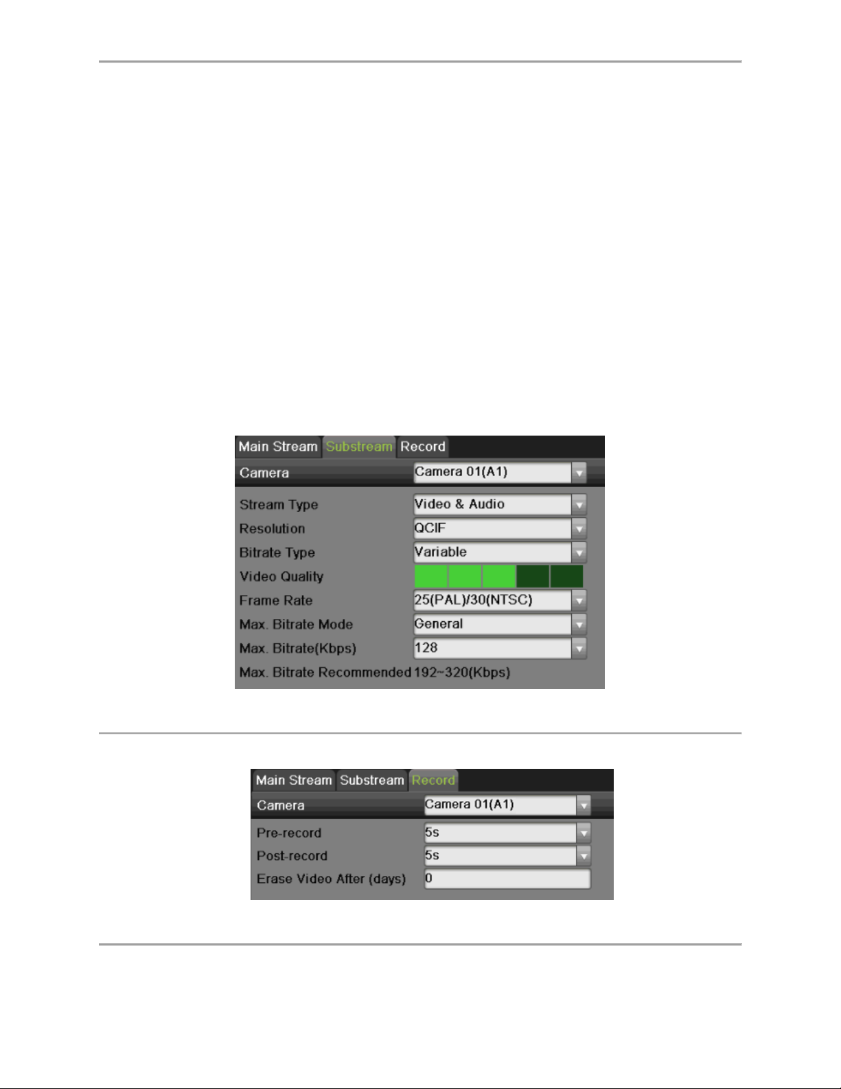
4) Select the camera resolution in the Resolution dropdown list. The options for the
camera resolution include 4CIF, 2CIF, CIF and QCIF.
5) Select the bit rate type in the Bitrate Type dropdown list. The options for the camera
bit rate type include Variable and Constant
6) Select the recording Frame Rate to use for the designated camera. A rate of 30 (Full
Frame) all the way down to 1/16 of a frame can be selected.
7) Set the video quality using the Video Quality slider. Increasing the video quality will
also increase the max. bit rate recommended. The max. bit rate can be adjusted
according to this recommend.
8) Select the max. bit rate mode in the Max. Bitrate Mode dropdown menu. The options
for the camera max. bit rate mode include General and Customize (32 to 8192 kbps).
9) Check the checkbox of record audio to enable or disable audio while recording.
10) Click the Apply button to save the settings.
11) Click the Copy button to copy the settings to other channels if the same settings can
also be used for other channels.
3. Select Substream tab, as shown in Figure 63, to configure the sub stream parameters.
The steps are the same as that of the main stream configuration.
Figure 63 Substream Settings Menu
4. Select record tab, as shown in Figure 64, to configure some parameters of recording.
Figure 64 Record Settings Menu
63
Page 65

1) Select the pre-record time. The pre-record time is the time in seconds to record
before a recording is triggered. Setting the pre-record time to MAX will allow the
DVR to use up to the maximum available buffer space for recording.
2) Select the Post-record time. The post-record time is the time in seconds to also
record after a recording has ended.
3) Enter the Erase Video After. The Erase Video After time denotes the amount of days
that files will be deleted after its initial recording. Setting the time to 0 will allow the
DVR to only delete and overwrite files when the HDD is full.
Note:
1. You must click the Apply button after adjusting the configuration of each tab
before you move on to adjust another one.
2. Event recordings are recordings that are triggered from motion detection and/
or from an external alarm.
3. If an event occurs during Continuous recording, the frame rate will
automatically switch to that set for Event recording.
4. For holiday settings, you can refer to Page 62.
Configuring Record Schedule
A record schedule allows you to schedule multiple time periods per day for recording. Setting up
a record schedule will allow you to further conserve disk space by recording only during the time
periods you would like to record at.
Note:
In this chapter, we take the record schedule procedure as an example, and the same procedure
can be applied to configure capture schedule. To setting the capture schedule, choose the
Capture tab in the Schedule interface.
Steps:
1. Enter the Schedule menu, shown in Figure 65 by going to Menu > Recording
Configuration > Schedule.
2. Select the Record tab to configure record schedule.
64
Page 66
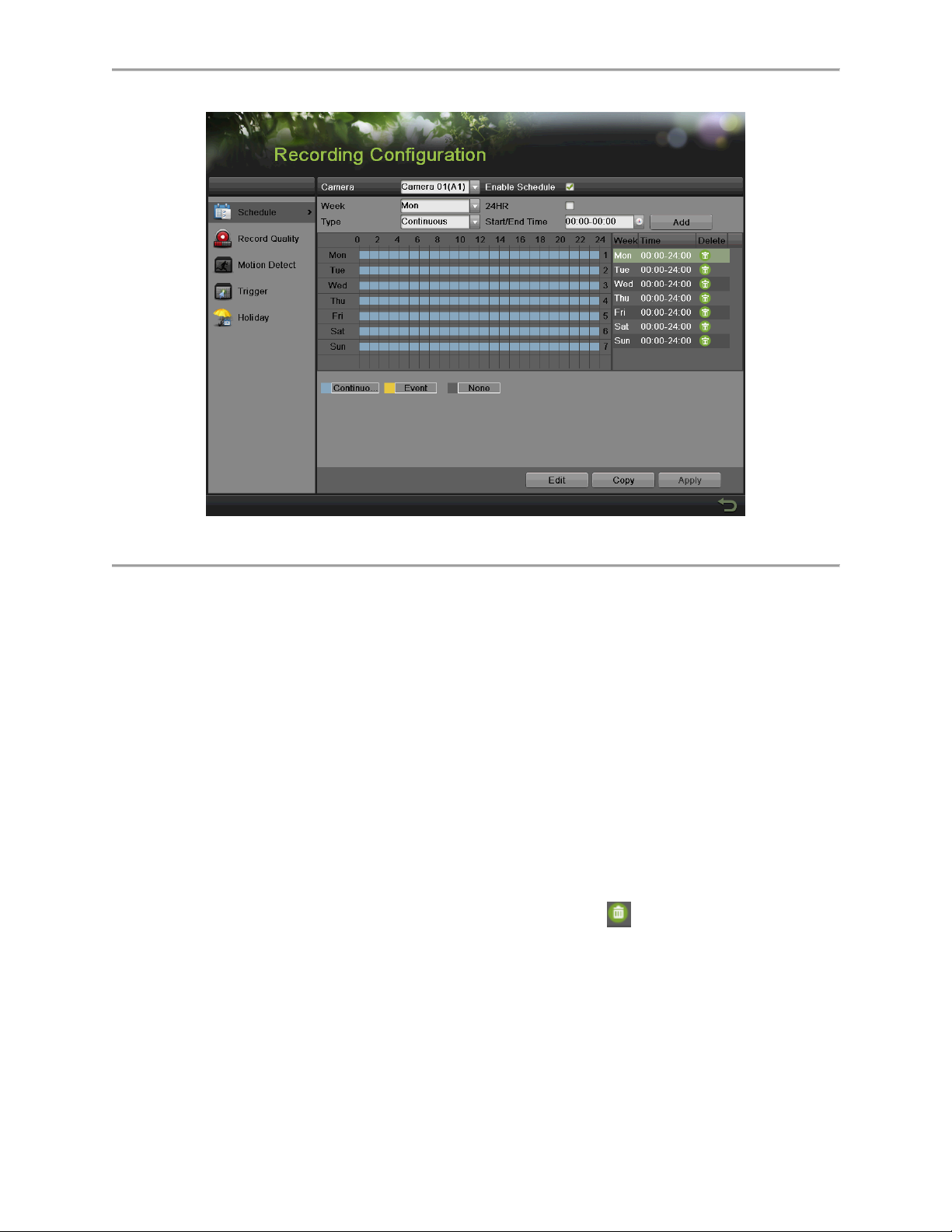
Figure 65 Record Schedule Configuration Menu
3. Select the camera to configure from the camera dropdown list.
4. Check the Enable Schedule checkbox to enable the record schedule. If the checkbox is
unchecked, the record schedule will be disabled.
5. Edit the record schedule. There are three ways to set the record schedule:
Instant edit
1) On the Record menu, select a day from Monday to Sunday to configure schedule for.
2) Setup time periods for schedule. If the 24HR checkbox is checked, recording will
occur over the entire day. To setup multiple time periods, uncheck 24HR and enter
the Start/End Time for the selected day. The start/End time are listed using a 24 hr
cycle (i.e. 18:00 is equivalent to 6:00pm). Up to 8 discontinuous periods can be
configured for each day.
3) Select recording type under Type for selected day of the week. Recording type
includes Continuous for continuous recording or Event when an event is triggered
(i.e., from detected motion) for the selected time period.
4) Select the Add button to add time frame to schedule. The newly added time frame
will appear in the schedule on the right. You can click to delete the selected time
period on the right. Continuous recordings are shown in blue on the schedule while
Event recordings are shown in yellow. An example of this can be seen in Figure 66.
65
Page 67
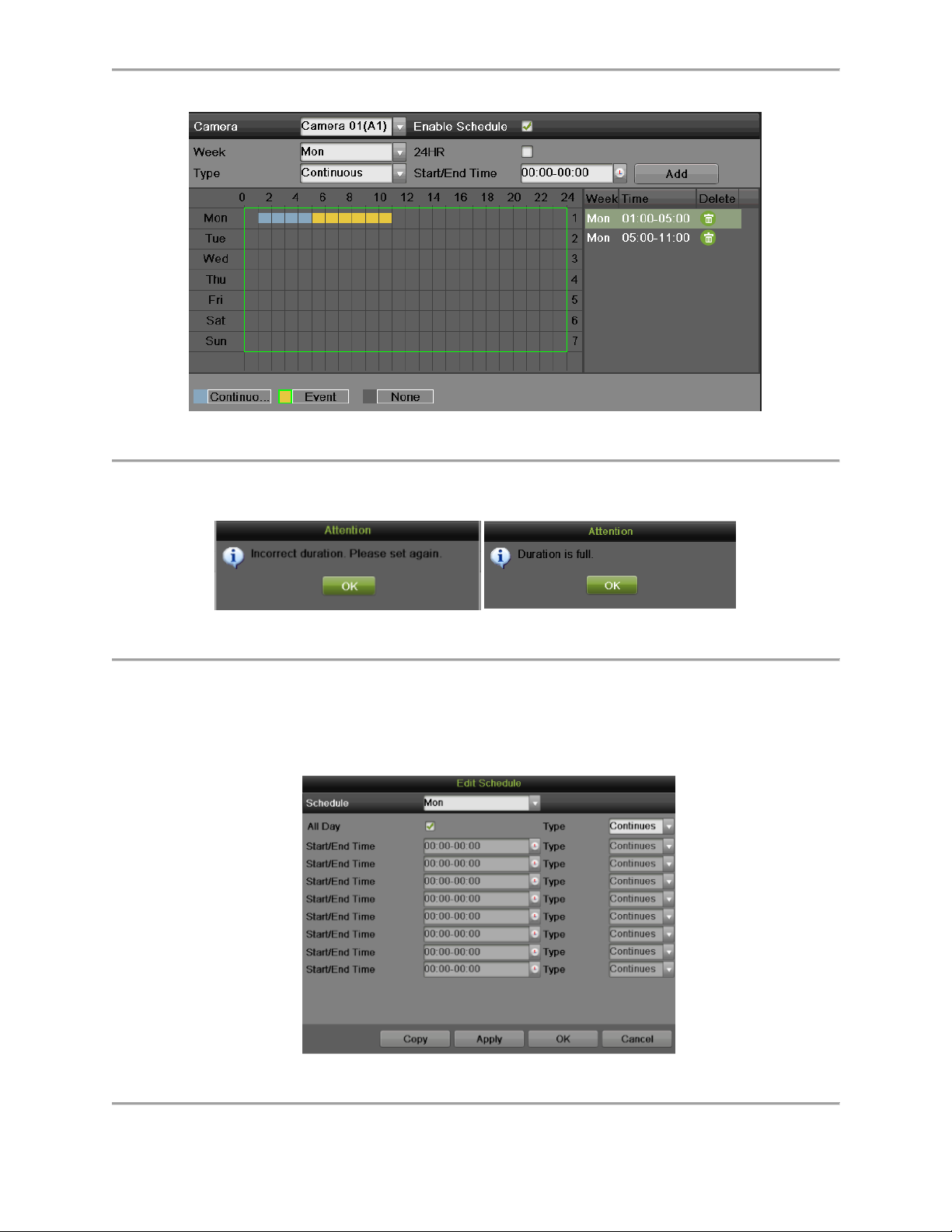
Figure 66 Record Schedule Configuration Example
5) If there are scheduling errors detected, error messages such as those shown in
Figure 67 will appear.
Figure 67 Schedule Configuration Error Messages
6) Repeat the above steps to set recoding schedule for other days in the week.
Edit the schedule
1) Click the Edit button on the bottom right to pop-up the Edit Schedule menu, as
shown in Figure 68.
Figure 68 Edit Schedule Menu
66
Page 68
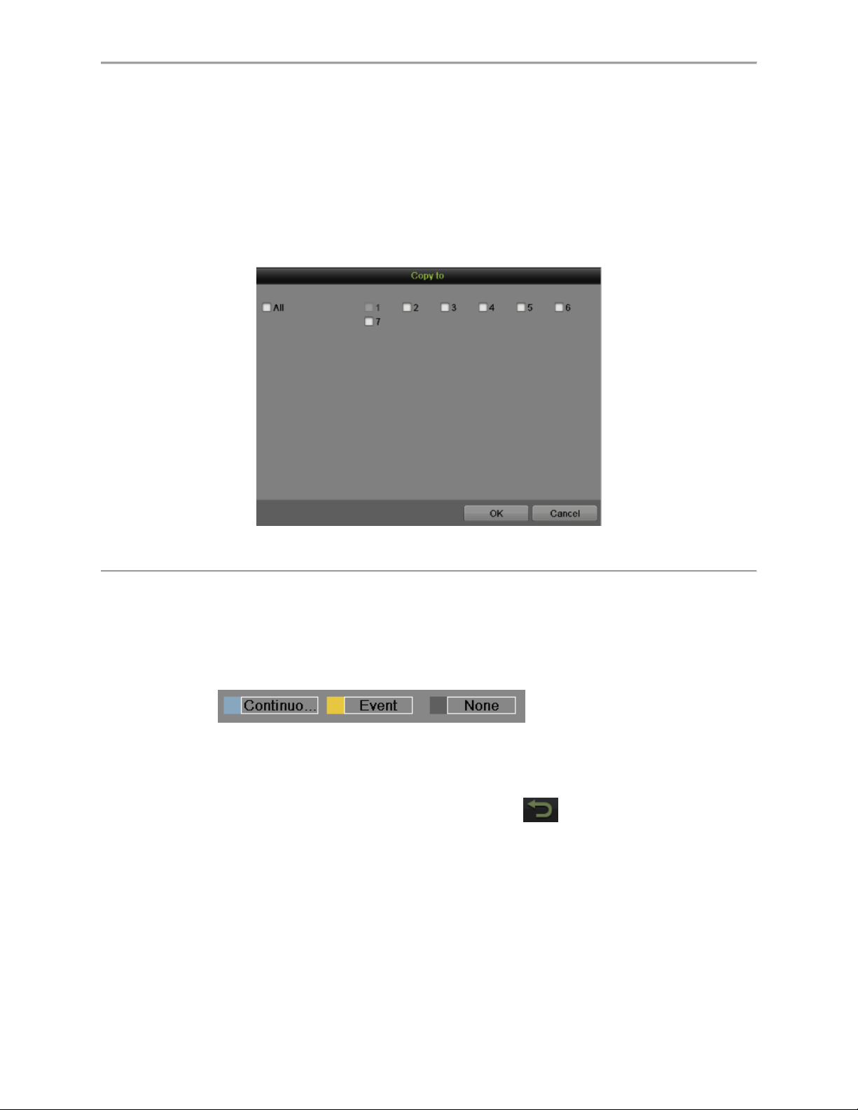
2) Select a day from Monday to Sunday.
3) Setup time periods for schedule. If the All Day checkbox is checked, recording will
occur over the entire day. To setup multiple time periods, uncheck All Day and enter
the Start/ End Time for the selected day. You can select recording type for each
period.
4) Click the Apply button to save the settings.
5) Repeat the above steps to set record schedule for other days in this week. If the
schedule can also be applied to other days, click the Copy button to pop-up a Copy
to box, as shown in Figure 69.
Figure 69 Copy to
6) Check the corresponding checkbox of the day to copy the record schedule to.
7) Click the OK button to save the settings and back to upper level menu or click the
Cancel button to back without saving.
8) Click the Apply button to save the settings and click OK to exit.
Draw the schedule
1) Click to select a recording type. None
means no recording.
2) Use the mouse to drag and draw time periods in the assigned area. Up to 8
discontinuous periods can be configured for each day.
3) Repeat the above steps to set record schedule for other days in the week.
4) Click the Apply button to save the settings or click to exit without saving.
6. Repeat the above steps to set record schedule for other channels. If the same schedule
can be applied to other channels, click the Copy button to pop-up a Copy to box, as
shown in Figure 70.
67
Page 69
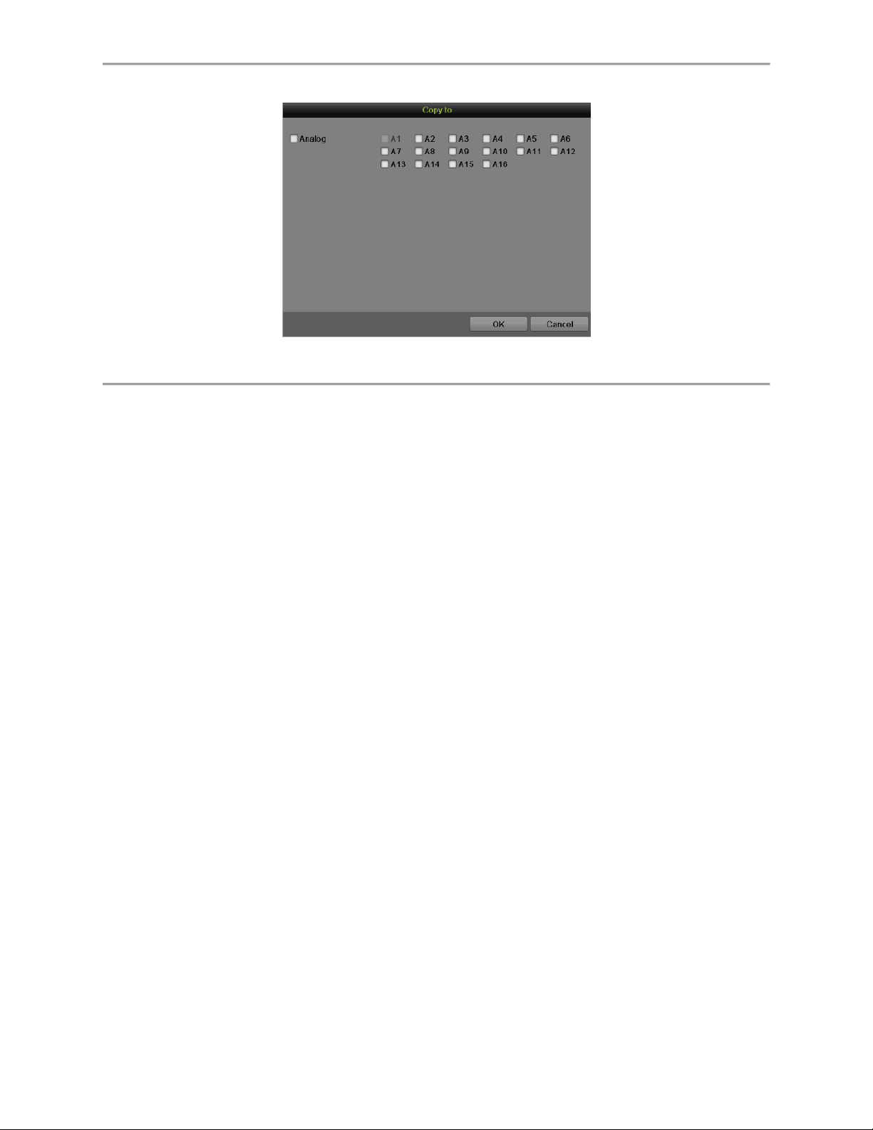
Figure 70 Copy to
7. Check the corresponding checkbox of other channels to copy the record schedule to.
8. Click the OK button to save the setting and back to upper level menu or click the Cancel
button to back without saving.
9. Click the Apply button to save the settings.
Note:
Enable the Start Recording in the Display Menu will also create a schedule in Schedule
Configuration. It will start all-day continue or event recording for all channels.
68
Page 70
Configuring Holiday Settings
Follow the steps to configure the holiday settings.
1. Enter the Holiday menu, shown in Figure 71 by going to Menu > Recording
Configuration > Holiday.
Figure 71 Holiday Settings Menu
2. Choose a holiday on the List show on the right. Click to pop up an Edit menu, as
shown in Figure 72.
Figure 72 Edit Menu
3. Edit the Holiday Name or use the default one.
4. Check the Enable checkbox.
5. Select Mode in the dropdown list. There are three different modes for the date format to
configure holiday schedule.
6. Set the start and end date.
7. Click the Apply button and OK to save settings and exit.
69
Page 71
C H A P T E R 6
Playback
Playing Back a Recording
Previously recorded files can be played back using the Playback Interface. You must first
search for recordings to play them back.
Understanding the Playback Interface
It’s important to understand how to use the Playback Interface to efficiently navigate through
recorded files. To access the Playback Interface, shown in Figure 73, go to Menu > Playback >
Record.
Figure 73 Playback Interface
Figure 74 Playback Menu
70
Page 72

Figure 74 shows some of the main features of the Playback Interface, which include:
Channel Selector: Select the channel to search for recordings on.
Calendar: Select the date to search for recordings on.
Timeline: Select the time to search for recordings on.
Preview: Shows a preview of the selected recording.
Playback Controls: Controls for playback of the selected recording.
Clip Backup Tools: Tools to backup clips from a recording.
Clip Playback Controls: Controls for playback of marked clip.
Full Screen: Enter full screen playback mode
Searching for Recorded Files
The Playback Interface allows for easy searching of recorded files. To search for recorded files
using the Playback Interface:
1. Enter the Playback menu, shown in Figure 73 by going to Menu > Playback > Record.
2. Select the channel to search for recordings on.
3. Select the date to search for recordings on using the calendar. The system date is
shown on the left of the calendar. You may change the month and year of the calendar
by clicking the left and right arrows next to the month and year .Dates with recordings in
the selected month and channel are displayed in light blue. Dates without recordings are
light gray. The active selected date is lighted up with a green box.
4. Click on the desired date that is highlighted in light blue to search for recordings. If
recordings exist, the timeline will be filled with blue bars to designate recorded files. The
playback marker, indicated by a green vertical line will automatically jump to the
beginning of the earliest recordings for the selected date. The marker can be moved to
any other location by clicking on the desired position on the blue bars or drag it.
5. Select in the Playback Controls to start playback of the recording.
Playing Back Recorded Files
After finding the recordings you would like to play back, you may use the Playback Controls to
navigate through the recording.
The controls found under Playback Controls include:
Play Forward Button: Button to playback recording.
Play Reverse Button: Button to playback recording in reverse.
Speed Down Button: Button to decrease play speed.
Speed Up Button: Button to increase play speed.
Mute Button: Button to enable and disable audio in playback mode.
Add Default Tag: Button to add default tag.
Add Customized Tag: Button to add customized tag and input tag name.
Edit Tag: Button to check, edit and delete tag(s).
Enter/Exit Full Screen Mode: Button to enter into and out of full screen mode.
71
Page 73

To playback recorded files:
1. Search and select recording to play back in the Playback Interface.
2. Click the Play Forward button to begin playback of selected recording and the Pause
button to pause playback.
3. You may slow down or speed up the playback speed by clicking the Speed Down/
Speed Up button.
4. You can click to zoom in/zoom out the timeline and select the exactly time.
5. Click the Full-Screen button to enter full-screen playback mode, shown in Figure 75.
Figure 75 Full-Screen Playback Mode
6. Clicking will return to the original playback mode.
7. Click the Mute button to turn on and off audio during playback.
8. Click to enable digital zoom. Once enabled, the regular recorded feed will be shown
in the lower right corner while the zoomed in view will be shown on the full screen. The
zoomed in region may be changed by moving the red rectangle in the regular recorded
feed window.
9. Click to add tag and manage it.
10. Click to control playback.
Playing Back Multiple Channels
You may also playback recordings from multiple channels simultaneously. To playback
recordings from multiple channels:
1. Search and select recording to playback in the Playback Interface.
2. Enter into Full Screen mode, shown in Figure 75 by clicking the Full Screen button.
72
Page 74

3. In Full-Screen mode, you may select additional channels to playback by clicking the
checkbox next to the desired camera in the Channel Selector panel. Playback will begin
simultaneously on the selected channels.
4. You may stop playback on any of the channels by un-checking the checkbox next to the
channel.
5. You can also select recording in Full Screen mode by double click the date on the
calendar.
Note:
Up to 16 channels can be played back at the same time.
Smart Search
In order to locate motion detection event easily and accurately in the playback progress line, the
users are allowed to analyze a certain area (scene) dynamically, and to get all of the related
motion detection events that occurred in this area.
Note:
The smart search function is available for single-channel playback only.
To use this function:
1. Enter the playback interface and play the video.
2. Move your mouse into the video window and drag an area for motion detection
analysis .The button is used for clearing all the area, and the button is used for
choosing the full screen area.
3. After selecting the area, click to search, you will get the motion detection events
easily from the long time line. Time line turns to red when motion detection events
happen.
4. You can get the scene you need conveniently by moving the green vertical line or you
can click and to move between the neighbor events.
5. To launch Smart Playback, press to start. Record periods with event will be played
in normal speed, others will be in fast speed.
6. You can also do the smart search in Full Screen mode, as shown in Figure 44 by
clicking to pop-up the tool bar as .
Playing Back Tags
1. Enter the Tag interface, shown in Figure 76 by going to Menu > Playback > Tag.
73
Page 75

Figure 76 Tag Playback Interface
2. Select channel on the Channel dropdown list.
3. Select tag type for Tag Keyword or All.
4. If tag type was Keyword, Keyword area was editable to allow user to set keywords for
fast searching.
5. Select start time and end time.
6. Select the pre-play and post-play time.
7. Click the Search button and the tag recording found will be listed in Result interface.
8. Click or double click the tag you want to play and it will be display in the Playback
interface as shown in Figure 77.
Figure 77 Tag Playback
9. Drag the timeline to the place you want to play.
74
Page 76

10. Click to enable or disable the audio.
11. Click to play back the pictures in Full Screen mode
12. Click to edit the tag name.
13. Click to delete the tag.
75
Page 77

C H A P T E R 7
Backup
Backing up Video Clips
Video clips can be backed up to various devices, such as USB flash drives, USB HDDs or a
DVD writer.
Selecting Video Clips
Video clips can be selected for backup in the Playback Interface using the controls found in the
Mark Clip For Export panel, shown in Figure 78.
Figure 78 Mark Clip For Export Controls
The controls found in the Mark Clip For Export panel include:
Start/Stop Button: Mark the starting/ending point for the video clip. When you click
the Start, it will turn to the Stop button.
Save Button: Save the selected video clip to the HDD.
Clear Button: Clear the selected video clip.
To select video clips in the Playback Interface:
1. Enter the Playback Interface, shown in Figure 79 by going to Menu > Playback > Record.
Figure 79 Playback Menu
76
Page 78

2. Search for the recorded files that you would like to select video clips from (See
Searching for Recorded Files on Page 64). Video clips can only be selected in single
playback mode.
3. Select the starting position of the video clip by clicking the desired location on the blue
recordings bar.
4. Click the Start button.
5. Select the ending position of the video clip, the same as starting position.
6. You can click to zoom in/zoom out the timeline and select the exactly time.
7. Click the Stop button.
8. The selected video clip time range will be shown at the bottom of the Playback Interface,
as seen in Figure 80.
Figure 80 Video Clip Time Range
9. You may play the video clip using the Play button or use the arrow keys
, which are shown below the timeline to progress
through the video one second, minute or hour at a time.
10. Click the Save button to save clip to the DVR. Clip must be first saved to the DVR before
it can be backed up to an external USB storage device or to a DVD writer. Clicking the
Clear button will remove the video clip.
11. Repeat steps 2-10 to select additional clips. If you would like to backup video clips at this
point, click the Clips Export button.
Note:
The Play, Save and Clear buttons are not available unless a completed video clip is selected. A
completed video clip has a start and end point marked by using the Start and Stop button.
Note:
The Start button is not available when there is still a video clip that has not been saved or
cleared.
Backing up Video Clips
After video clips have been selected in the Playback Interface, you may back them up to an
external USB storage device or DVD writer by going to the Export menu.
To backup video clips:
1. Enter the Clips Export menu, shown in Figure 81 by first going to Menu > Playback. In
the Playback menu, click the Clips Export button.
77
Page 79

Figure 81 Clips Export Interface
2. If video clips were successfully saved to the HDD using the Playback Interface, they will
be listed in the Clips Export interface. The camera number as well as the time range and
clip size would be listed.
3. Select the video clips you would like to backup by checking the checkbox next to the
desired clips. You may also click to play and review the clip. Video clips can be
deleted by clicking or by clicking the Delete button to delete the selected clips.
Check the Channel No. box will choose all clips.
4. Connect at least one USB storage device to the DVR. If the device is compatible with the
DVR, it will automatically be detected. Select the backup device from the Device Name
dropdown menu.
5. If the available space on the storage device is adequate, select the Export button to
begin backup of the selected clips.
6. After clips have been backed up, you may click the Cancel button to return to the
Playback Interface.
Note:
If the USB storage device has not been properly initialized and formatted, you may click on the
Format button to do so.
Formatting a storage device will permanently delete ALL the files on that device.
There is also NO WARNING MESSAGE after clicking the Format button to format the storage
device. Please proceed with caution and backup all critical data from the storage device before
formatting.
Backing up Recorded Files
Not only can video clips be backed up, full recorded files can also be backed up to a storage
medium.
To back up recorded files:
1. Search for recorded files using the File Management menu (See Searching for Recorded
Files on Page 64).
2. Select the files you would like to back up by checking the box next to the file. You may
also check the Channel No. box to select all files. The total required space will be shown
next to Total size.
78
Page 80
3. You can also check the checkbox of Merge files to export.
4. Click the Export button; this will take you to the Export menu, as shown in Figure 82.
Figure 82 Files Backup Menu
5. In the Export menu, connect a USB storage device and click the Refresh button. If the
device is detected, a list of its file contents as well as the available free space will be
shown.
6. You may delete files on the USB storage device to free up additional storage space by
clicking the Delete button on the selected file. You may also format the device by clicking
the Format button. Formatting will remove ALL files from the device.
7. When there is sufficient storage space for backup, click the Export button. A backup
progress bar will be shown.
8. Click the OK button once backup has completed.
Figure 83 Export Finished Message
9. Click the Cancel button to return to the File Management menu.
10. You can also click Quick Export in the Record menu to export all the record files for the
selected channel.
79
Page 81
C H A P T E R 8
System Configuration
Configuring Network Settings
Network settings must be configured before you’re able to use your DVR over the network.
Configuring General Settings
To configure network general settings:
1. Enter the Network Configuration menu, shown in Figure 84 by going to Menu > System
Configuration > Network.
Figure 84 Network Settings Menu
2. Select the General tab. The current network settings are displayed on the right side of
the menu, shown in
3. Figure 85.
Figure 85 Network Settings Menu
80
Page 82

4. If you have a DHCP server running and would like your DVR to automatically obtain an
IP address and other network settings from that server, check the DHCP checkbox.
5. If you would like to configure your own settings, enter the settings for:
IP Address: IP address you would like to use for your DVR.
Subnet Mask: Subnet Mask of network.
Default Gateway: IP address of your Gateway. Typically the IP address of your
router.
DNS Server: The preferred and alternate Domain Name System (DNS) Server to be
used with your DVR.
6. Click the Apply button to save the settings.
Configuring DDNS
Dynamic DNS allows you to create a hostname and associate it to your IP address, making
access to your DVR over the internet easier. To configure DDNS:
1. Select the DDNS tab to enter the DDNS settings interface, as shown in Figure 86.
Figure 86 DDNS Settings Menu
2. Check ezviz Cloud to enable the P2P service.
3. Check Stream Encryption to use higher security-level data stream.
4. Check the Enable DDNS checkbox.
5. Select a DDNS type from the DDNS Type selection box. Five different DDNS types are
selectable: IPServer, DynDNS, PeanetHull, NO-IP, hkDDNS.
IPServer: Enter Server Address for IPServer.
DynDNS:
1) Enter Server Address for DynDNS.
2) Enter the domain obtained from the DynDNS website in the Domain Name
textbox.
3) Enter the User Name and Password registered in the DynDNS website.
PeanutHull: Enter the User Name and Password obtained from the PeanutHull
website.
NO-IP:
1) Enter Server Address for NO-IP.
81
Page 83
2) Enter the domain obtained from the DynDNS website (www.no-ip.com) in the
Domain Name textbox.
3) Enter the User Name and Password registered in the NO-IP website.
HiDDNS:
1) The Server Address defaults to www.hik-online.com.
2) Enter the Device Domain Name. The domain name can only contain the lower-
case letter, numeric and ‘-’, and it must start with the lower-case letter and cannot
end with ‘-’.
3) If you have more than one device, you can register an account on www.hik-
online.com to do some management.
6. Click the Apply button to save the settings.
Configuring SNMP
You can use SNMP protocol to get device status and parameters related information. To
configure SNMP:
1. Select the SNMP tab to enter the SNMP settings interface, as shown in Figure 87.
Figure 87 SNMP Settings Menu
2. Check the Enable SNMP checkbox.
3. Enter the IP address of SNMP host in the Trap Address textbox.
4. Enter the port of SNMP host in the Trap Port textbox
5. Click the Apply button to save the settings.
Configuring UPnP
Universal Plug and Play (UPnP) can permits the device seamlessly discover the presence of
other network devices on the network and establish functional network services for data sharing,
communications, etc. You can use the UPnP function to enable the fast connection of the
device to the WAN via a router without port mapping. To configure UPnP:
1. Select the NAT tab to enter the UPnP settings interface, as shown in Figure 88.
82
Page 84

Figure 88 UPnP Settings Menu
2. Check the Enable UPnP checkbox.
3. Select the Mapped Type. There are two types:
Auto: Automatic mapping port 8000, 80, 554.
Manual: Edit the port by click .
4. Click the Apply button to save the settings.
Configuring More Settings
You can configure alarm host and port by selecting the more setting tab, as shown in Figure 89.
Figure 89 More Settings Menu
1. Alarm Host: Send the alarm event or exception message to the alarm host when an
alarm is triggered. The remote alarm host must have the CMS (Client Management
System) Software installed.
Enter the IP address of the remote PC on which the CMS Software is installed in.
Enter the alarm monitoring port in Alarm Host Port, which must be the same as the
port configured in the software.
83
Page 85

2. Port:
Server Port: Enter the Server Port which designates the port to be used with the
client software.
HTTP Port: Enter the HTTP Port which refers to the one to be used with the built-in
Web Server.
Multicast IP: Enter the Multicast IP to enable multicast.
RTSP Port: Enter the PTSP Port. PTSP is a network control protocol designed for
use in entertainment and communication systems to control streaming media
servers.
3. More:
Enable Telnet to launch telnet service, but it may result in security issues.
Enable High-speed Download to launch higher speed of downloading files, but it
may lead to retard in local operation.
4. Click Apply to save the network settings and click to return to the previous menu.
Click without clicking Apply will quit out of the menu without saving settings.
Managing User Accounts
By default, your DVR comes with one user account, the Administrator account. The
Administrator user name is admin and the password is 12345. The default password for
Administrator should be changed right away for security reasons. The Administrator has the
authority to add, delete or configure parameters for many of the system functions.
Changing Password
You can change the default password by going to Menu > System Configuration > User, as
shown in Figure 90.
Figure 90 User Settings Menu
84
Page 86

To change the password:
1. Click to pop up the Edit User menu, as shown in Figure 91.
Figure 91 Edit User Menu
2. Enter the old password in the Old Password textbox.
3. Check the Change Password checkbox.
4. Enter the new password in the Password textbox.
5. You can enter the User’s MAC Address of the remote PC. If it is configured and enabled,
it only allows the remote user with this MAC address to access the device.
6. You can also enter the User’s IP Address of the remote PC. If it is configured and
enabled, it only allows the remote user with this IP address to access the device.
7. Click the OK button to save the setting and back to the up level.
Adding a New Remote/Local User
You may add up to 31 new users to your DVR.
To add new users:
1. On the User interface shown in Figure 59, click Add to enter Add User interface, as
shown in Figure 92.
Figure 92 Add User Menu
85
Page 87

2. Enter the information for new user, including User Name, Password, Level and User’s
MAC and IP Address.
Level: Set the user level to Guest or Operator. Different user levels have different default
operating permission.
Guest: Guest has the default permission of local log search and remote log search.
Operator: Operator has the default permission of local log search, remote log
search, two-way audio and camera configuration.
3. Click the OK button to confirm adding the user. Once a new user has been created, the
fields behind Users will become editable, as shown in Figure 93.
Figure 93 User Settings Menu
Changing the permission of User
The Administrator can change the permission of both guest and operator. To change the
permission:
1. Enter the User menu, shown in Figure 94 by going to Menu > System Configuration >
User.
2. Click to enter the Permission interface, as shown in Figure 91, 92, 93.
Figure 94 Local Configuration Permission Settings Menu
86
Page 88

Figure 95 Remote Configuration Permission Settings Menu
Figure 96 Camera Configuration Permission Settings Menu
3. Set the operation permission of Local Configuration, Remote Configuration and Camera
Configuration for the user.
Local Configuration:
Local Log Search: Searching and viewing logs and system information of DVR.
Local Parameters Settings: Configuring parameters, restoring factory default
parameters and importing/exporting configuration files.
Local Camera Management: Adding, deleting and editing of network camera(s).
Local Advanced Operation: Operating HDD management upgrading system
firmware, clearing I/O alarm output.
Local Shutdown/Reboot: Shutting down or rebooting the DVR.
Remote Configuration:
Remote Log Search: Remotely viewing logs that are saved on the DVR.
Remote Parameters Settings: Remotely configuring parameters, restoring factory
default parameters and importing/exporting configuration files.
Remote Camera Management: Remotely adding, deleting and editing of network
camera(s).
87
Page 89

Remote Serial Port Control: Configuring settings for RS-485 ports.
Remote Video Output Control: Sending remote button control signal.
Two-Way Audio: Realizing two-way radio between the remote client and the DVR.
Remote Alarm Control: Remotely arming (notify alarm and exception message to
the remote client) and controlling the alarm output.
Remote Advanced Operation: Remotely operating HDD management upgrading
system firmware, clearing I/O alarm output.
Remote Shutdown/Reboot: Remotely shutting down or rebooting the DVR.
Camera Configuration:
Local Video Export: Locally exporting recorded files of the selected camera (s).
Local Playback: Locally playing back recorded files of the selected camera (s).
Local PTZ Control: Locally controlling PTZ movement of the selected camera (s).
Local Manual Operation: Local manual operation of the selected camera (s).
Remote Live View: Remotely viewing live video of the selected camera (s).
Remote Playback: Remotely playing back recorded files of the selected camera (s).
Remote PTZ Control: Remotely controlling PTZ movement of the selected camera
(s).
Remote Manual Operation: Remotely manual operation of the selected camera (s).
4. Click the Apply button to save the parameters.
Note:
If you forget the password of your DVR, contact your supplier with the serial number of your
DVR to obtain a secure code to reset your DVR.
Note:
User settings only appear on the list of System Configuration when login with Administrator
accounts.
Deleting a User
To delete a user from the DVR:
1. Enter the User menu, shown in Figure 90 by going to Menu > System Configuration >
User.
2. Select a user and click to delete.
3. Click Yes to confirm the deletion of user or click No to cancel.
Editing a User
To edit a user:
1. Enter the User menu, shown in Figure 90 by going to Menu > System Configuration >
User.
2. Select a user and click to edit user.
3. Edit user information including user name, password, level and MAC address.
4. Click the OK button to save and exit.
Note:
User password can be both numbers and characters. You can click the button on the
password editable fields to enter characters.
88
Page 90

Create a Password Key
To create a password key which can reset password for admin user:
1. Enter the User menu, shown in Figure 90 by going to Menu > System Configuration >
User.
2. Click on to enter the password key export menu, as shown below.
Figure 97 Password Key menu
3. Choose the device name, and select the dictionary and click on Export button to export
password key.
Switch User
On the main menu (see in Figure 90), information about users are show on the lower left corner,
, click to switch users.
Figure 98 Main Menu
89
Page 91
Reset admin user’s password with Password Key
If user forgets its admin password, he can use the previous created password key to reset its
password.
To reset the password:
1. Click on the red box area to enter the password recovery menu.
Figure 99 Main Menu
2. Click on the Password Key button in the menu shown below.
Figure 100 Main Menu
3. Import the Password Key from external storage device, and reset default password.
90
Page 92

Figure 101 Main Menu
91
Page 93

Reset Password
Device Type
Model Number
Firmware Version
Value Series IP Camera
DS-2CD2xxx
V5.3.0
Smart Series IP Camera
DS-2CD4xxx
V5.3.0
NVR/Hybrid
DS-9016HWI-ST
DS-96xxNI-ST
DS-7716NI-SP/16
V3.1.5
Plug-n-Play NVR
DS-76xxNI-EI(E2)/P
V3.1.0
Turbo DVR
DS-72xxHGHI-SH
DS-73xxHQHI-SH
V3.1.6
Super NVR
DS-96128NI-E24/H
DS-96256NI-E24/H
TBD
(New Hikvision Secure Activation Password Strategy)
To reset passwords with the new Hikvision Secure Activation Password Strategy, you must use
SADP Tools software (v2.2.3.5 Build 20150408) or later (Figure 102). It can be downloaded
from our download portal at Helpdesk.usa@hikvision.com. It can be used on front-end and
back-end devices with firmware shown in the following table:
Device Firmware with Secure Activation
Figure 102 You need to download a new version of the SADP Tool software (v2.2.3.5 Build 20150408)
NOTE: Once you update your DVR/NVR or camera firmware, it cannot be downgraded
to a previous version; the upgrade is not reversible.
By using the new SADP Tool you can determine if the front-end device is using OLD or NEW
firmware. If your device has old firmware v3.1.0 (Figure 103), you’ll need to reset the password
by using the old procedure. With the new firmware v3.3.0 (Figure 104), the default username
and password (admin, 12345) are no longer applicable. The user will be prompted to assign a
new password during the initial password reset attempt.
92
Page 94

Figure 103 New SADP Tool lets you determine if front-end device is using OLD firmware (V3.1.1build 150122
shown)…
Figure 104…or NEW firmware (V3.3.0build 150328 shown)
1. In the SADP Tool, highlight your device, click [Browse] (…), and select the path where you saved the
“Encrypt.xml” file (Figure 105).
Figure 105 Select device again and click [Browse] to locate the path where you saved the “Encrypt.xml” file
93
Page 95

8. Create a password of your choice by entering a new password into the “New Password” field on the
bottom right of the screen (Figure 108). See “Reference” section on page 15 for guidelines.
9. Retype the password into the “Confirm Password” field.
10. After the password has been entered and confirmed, click [Import] (Figure 106) to import the
“Encrypt.xml” file you received and saved from Hikvision Technical Support.
Figure 106 Set up a password by clicking [New Password] and [Confirm Password], then click [Import]
11. A “Reset password succeed” message will appear (Figure 107).
12. Press the “X” in the top right corner of the pop-up confirmation window to dismiss the window.
Figure 107 “Reset password succeed” message will appear
94
Page 96
Reference
STRENGTH LEVEL
DESCRIPTION
Level 0 (Risky)
Cameras will not accept a Level 0 password
Password length is fewer than eight characters, contains
only one type of character, is the same as the user name,
and/or is the mirror writing of the user name. This type of
password will not be accepted.
Level 1 (Weak)
Cameras will accept a Level 1 password
Password contains two types of characters. The
combination is number + lowercase letter or number +
uppercase letter, and the password length is at least eight
characters. This type of password will be accepted.
Level 2 (Medium)
Cameras will accept a Level 2 password
Password contains two types of characters. The
combination is neither number + lowercase letter nor
number + uppercase letter, and the password length is at
least eight characters. This type of password will be
accepted.
Level 3 (Strong)
Cameras will accept a Level 3 password
Password contains more than three types of characters, and
the password length is at least eight characters. This type of
password will be accepted.
Password Strength Requirements
Hikvision’s new login procedure requires users to create a new password for the admin account
upon the first login to all devices. The password must contain 8 to 16 characters, combining
numbers, lowercase letters, uppercase letters, and special characters. At least two types of the
above-mentioned characters are required. The system will check the password strength; “Risky”
passwords will not be accepted.
- The password strength will be displayed, accompanied by a color indicator:
• Level 0–Risky (no indicator): Not acceptable
• Level 1–Weak (pink indicator): Acceptable
• Level 2–Medium (yellow indicator): Acceptable
• Level 3–Strong (green indicator): Acceptable
- Bar length indicates strength level.
- Activation will not be allowed unless the password is of acceptable strength (“Weak,” Figure 110,
“Medium,” Figure 111, or “Strong,” 错误!未找到引用源。). If the password is of unacceptable
strength (“Risky,” Figure 108), a warning box will be displayed (Figure 109).
Password Strength Levels
NOTE: Types of characters are lowercase letters, uppercase letters,
numbers, and special characters. Only ASCII characters are
allowed.
NOTE: The strength level indicator colors can vary by activation process, model number, and device
type.
95
Page 97
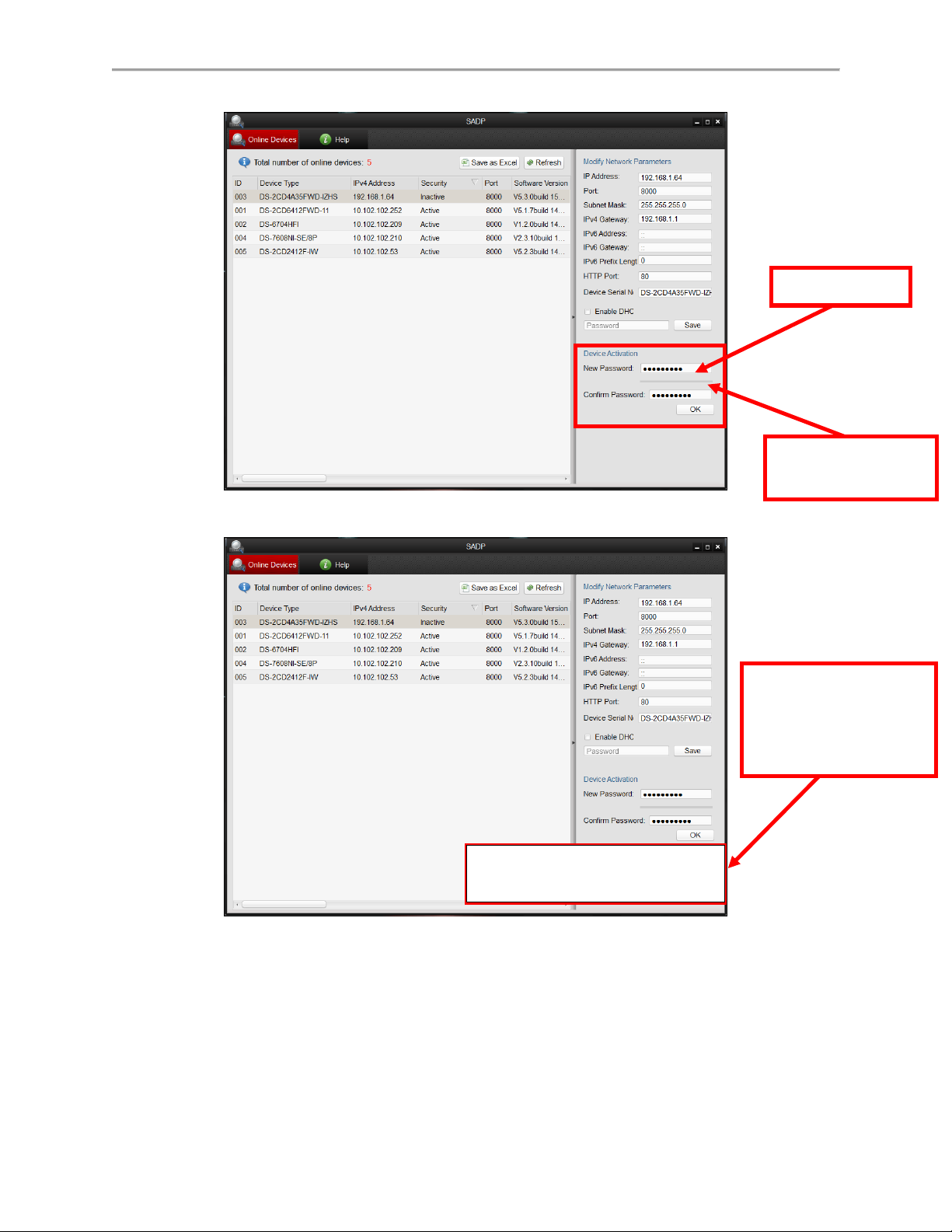
Figure 108 Password Field with “Risky” Unacceptable Password
Risky Password
The “Strength Meter”
does not light up
A message indicates
that the password has
to meet minimum
requirements
Valid password range [8-16]. You can use a combination
of numbers, lowercase, uppercase and special
characters for your password with at least two kinds of
them contained.
Figure 109 “Risky” Unacceptable Password Warning Message
96
Page 98
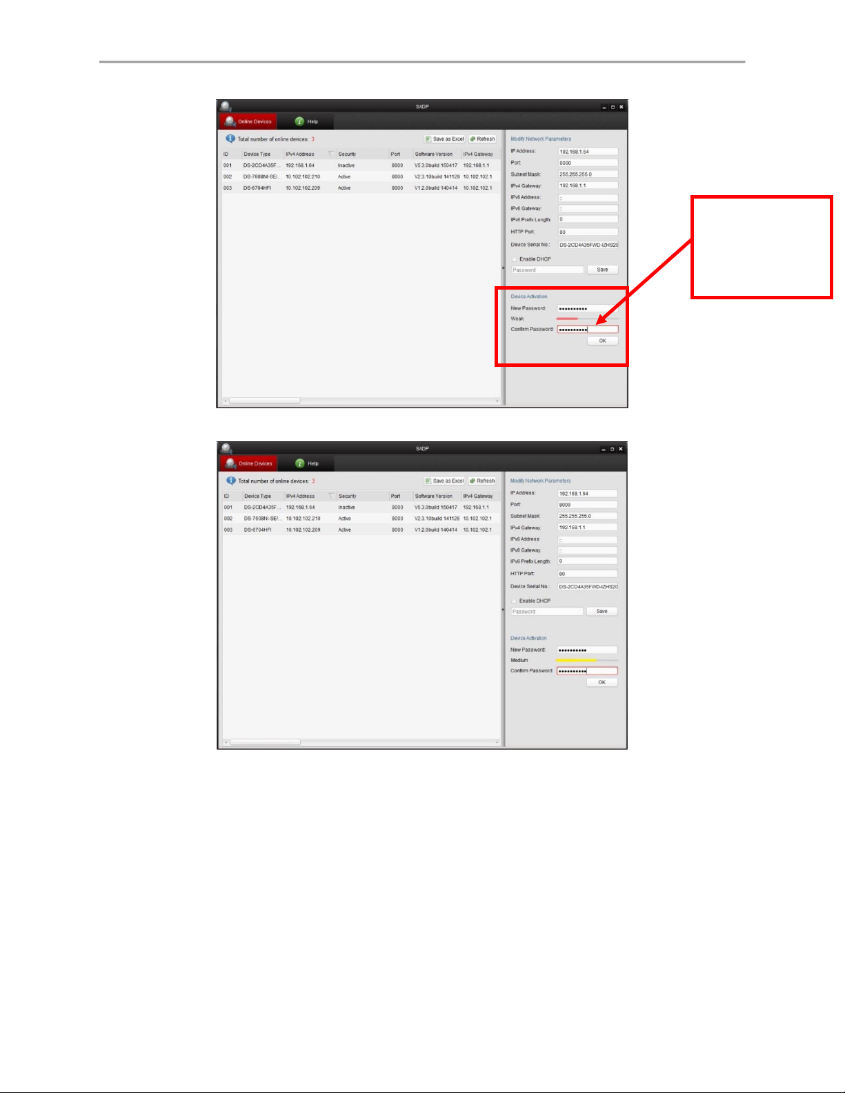
Figure 110 Password Field with Acceptable “Weak” Strength Password
NOTE: The
password strength
is shown with a
color indicator.
Figure 111 Password Field with Acceptable “Medium” Strength Password
97
Page 99
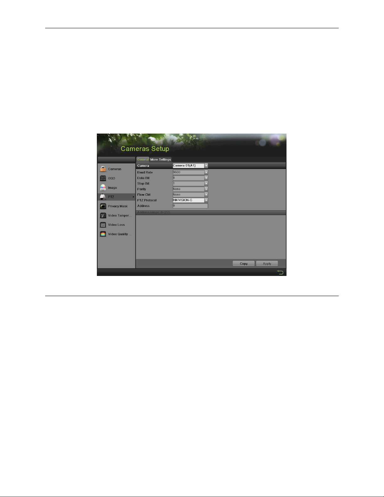
Configuring PTZ Cameras
Configuring Basic PTZ Settings
Settings for a PTZ camera must be configured before it can be used. Before proceeding, verify
that the PTZ and RS-485 of the DVR are connected properly.
To configure PTZ settings:
1. Enter the PTZ menu, shown in Figure 112 by going to Main Menu > Cameras Setup >
PTZ.
Figure 112 General Settings of PTZ Configuration
2. Select the General tab.
3. Select the camera to configure in the Camera dropdown list.
4. Configure PTZ settings, including those of Baud Rate, Data Bit, Stop Bit, Parity, Flow
Ctrl, PTZ Protocol and Address according to the parameters of the PTZ camera(s).
5. If the same configuration can be applied to other PTZ channels, click the Copy button.
6. Click the Apply button to save the settings.
To test and verify PTZ settings:
1. Enter the PTZ Configuration menu by going to Menu > Cameras Setup > PTZ.
2. Select the More Settings tab, shown in Figure 113.
98
Page 100

Figure 113 More Settings of PTZ Configuration
3. Select the camera to test in the Camera dropdown list.
4. Using the Directional buttons and other PTZ control buttons (Zoom +/-, Focus +/-, Iris +/-,
the speed of the PTZ movement), test the functionality of the PTZ camera. If PTZ
camera and protocol supports it, you may also click the Auto-Scan button to test its
function. PTZ controls buttons are shown in Figure 114.
Figure 114 PTZ Controls Button
5. If PTZ camera is not working properly, make sure PTZ is connected and configured with
the correct settings under the General tab.
Customizing PTZ Presets, Patterns and Patrols
Your DVR allows you to customize presets, patterns and patrols for a connected PTZ camera. A
PTZ camera must first be configured before PTZ presets, patterns and patrols can be
customized (See Configuring Basic PTZ Settings).
To customize PTZ presets:
1. Enter the PTZ menu by going to Menu > Cameras Setup > PTZ.
2. Select the More Settings tab, as shown in Figure 113.
3. Select Save Preset and move the camera to the desired position using the PTZ control
buttons.
4. Double-click on a preset number. The current position of the PTZ camera will be set for
the selected preset number.
99
 Loading...