

Page 1

DS-3E0318P-E/DS-3E0326P-E
User Manual
UD.6L0202D2008A01
Page 2

User Manual of Network Video Recorder
User Manual
COPYRIGHT ©2016 Hangzhou Hikvision Digital Technology Co., Ltd.
ALL RIGHTS RESERVED.
Any and all information, including, among others, wordings, pictures, graphs are the properties of Hangzhou
Hikvision Digital Technology Co., Ltd. or its subsidiaries (hereinafter referred to be “Hikvision”). This user
manual (hereinafter referred to be “the Manual”) cannot be reproduced, changed, translated, or distributed,
partially or wholly, by any means, without the prior written permission of Hikvision. Unless otherwise stipulated,
Hikvision does not make any warranties, guarantees or representations, express or implied, regarding to the
Manual.
About this Manual
This Manual is applicable to DS-3E0318P-E/DS-3E0326P-E.
The Manual includes instructions for using and managing the product. Pictures, charts, images and all other
information hereinafter are for description and explanation only. The information contained in the Manual is
subject to change, without notice, due to firmware updates or other reasons. Please find the latest version in the
company website (http://overseas.hikvision.com/en/
Please use this user manu al under the guidance of professionals.
Trademarks Acknowledgement
and other Hikvision’s trademarks and logos are the properties of Hikvision in various jurisdictions.
Other trademarks and logos mentioned below are the properties of their respective owners.
Legal Disclaimer
TO THE MAXIMUM EXTENT PERMITTED BY APPLICABLE LAW, THE P RODUCT DESCRIBED, WITH
ITS HARDWARE, SOFTWARE AND FIRMWARE, IS PROVIDED “AS IS”, WITH ALL FAULTS AND
ERRORS, AND HIKVISION MAKES NO WARRANTIES, EXPRESS OR IMPLIED, INCLUDING WITHOUT
LIMITATION, MERCHANTABILITY, SATISFACTORY QUALITY, FITNESS FOR A PARTICULAR
PURPOSE, AND NON-INFRINGEMENT OF THIRD PARTY. IN NO EVENT WILL HIKVISION, ITS
DIRECTORS, OFFICERS, EMPLOYEES, OR AGENTS BE LIABLE TO YOU FOR ANY SPECIAL,
CONSEQUENTIAL, INCIDENTAL, OR INDIRECT DAMAGES, INCLUDING, AMONG OTHERS,
DAMAGES FOR LOSS OF BUSINESS PROFITS, BUSINESS INTERRUPTION, OR LOSS OF DATA OR
DOCUMENTATION, IN CONNECTION WITH THE USE OF THIS P RODUCT, EVEN IF HIKVISION HAS
BEEN ADVISED OF THE POSSIBILITY OF SUCH DAMAGES.
REGARDING TO THE PRODUCT WITH INTERNET ACCESS, THE USE OF PRODUCT SHALL BE
WHOLLY AT YOUR OWN RISKS. HIKVISION SHALL NOT TAKE ANY RESPONSIBILITES FOR
ABNORMAL OPERATION, PRIVACY LEAKAGE OR OTHER DAMAGES RESULTING FROM CYBER
ATTACK, HACKER ATTACK, VIRUS INSPECTION, OR OTHER INTERNET SECURITY RISKS;
HOWEVER, HIKVISION WILL PROVIDE TIMELY TECHNICAL SUP PORT IF REQUIRED.
SURVEILLANCE LAWS VARY BY JURISDICTION. P LEASE CHECK ALL RELEVANT LAWS IN YOUR
JURISDICTION BEFORE USING THIS PRODUCT IN ORDER TO ENSURE THAT YOUR USE CONFORMS
THE APPLICABLE LAW. HIKVISION SHALL NOT BE LIABLE IN THE EVENT THAT THIS PRODUCT IS
USED WITH ILLEGITIMATE PURPOSES.
IN THE EVENT OF ANY CONFLICTS BETWEEN THIS MANUAL AND THE APPLICABLE LAW, THE
LATER P REVAILS.
).
1
Page 3

User Manual of Network Video Recorder
Regulatory Information
CE Mark Warning
This is a Class A product. In a domestic environment, this product may cause radio inter ference, in which case the
user may be required to take adequate measures.
For Pluggable Equipment, the socket-outlet shall be installed near the equipment and shall be easily accessible.
WARNING: The mains plug is used as disconnect device, the disconnect device shall remain readily operable.
The Product is designed for IT Power Distribution System.
NOTE: (1) The manufacturer is not responsible for any radio or TV interference caused by unauthorized
modifications to this equipment. (2) To avoid unnecessary radiation interference, it is recommended to use a
shielded RJ45 cable.
FCC Statement
This equipment has been tested and found to comply with the limits for a Class A digital device, pursuant to part
15 of the FCC Rules. These limits are designed to provide reasonable protection against harmful interference when
the equipment is operated in a commercial environment . This equipment generates, uses, an d can radiate radio
frequency energy and, if not installed and used in accordance with the instruction manual, may cause harmful
interference to radio communications. Operation of this equipment in a residential area is likely to caus e harmful
interference in which case t he user will be requir ed t o correct the interference at hi s own expense.
This device complies with part 15 of the FCC Rules. Operation is subject to the following two conditions: (1) This
device may not cause harmful interference, and ( 2) this device must accept any int erference received, including
interference that may cau s e undesired operation. The manufacturer is not responsible for any radio or TV
interference caused by unauthorized modifications to this equipment.
Caution!
Any changes or modifications not expressly approved by the party responsible for compliance could void the user's
authority to operate the equipment.
NOTE: (1) The manufacturer is not responsible for any radio or TV interference caused by unauthorized
modifications to this equipment. (2) To avoid unnecessary radiation interference, it i s recommended to use a
shielded RJ45 cable.
IC
CAN ICES-3(A)/NMB-3(A)
2
Page 4

User Manual of Network Video Recorder
Safety Instruction
These instructions are intended to ensure that user can use the product correctly to avoid danger or property loss.
The precaution measure is divided into “Warnings” and “Cautions”
Warnings: Serious injury or death may occur if any of the warnings are neglected.
Cautions: Injury or equipment damage may occur if any of the cautions are neglected.
Warnings Follow these safeguards to prevent
serious injury or death.
Cautions Follow these precautions to
prevent potential injury or material damage.
Warnings
● Proper configuration of all passwords and other security settings is the responsibility of the installer and/or
end-user.
● In the use of the product, you must be in strict compliance with the electrical safety regulations of the nation
and region. Please refer to technical specifications fo r detailed information.
● Input voltage should meet both the SELV (Safety Extra Low Voltage) and the Limited Power Source with
100~240 VAC or 12 VDC according to the IEC60950-1 standard. Please refer to technical specificati ons for
detailed information.
● Do not connect several devi ces to one power adapter as adapter overload may cause over-heating or a fire
hazard.
● Please make sure that the plug is firmly connected to the power socket.
● If smoke, odor or noise rise from the device, turn off the power at once and unplug the power cable, and then
please contact the service center.
3
Page 5

User Manual of Network Video Recorder
Preventive and Cautionary Tips
Before connecting and operating your device, please be advised of the following tips:
• Ensure unit is installed in a well-ventilated, dust-free environment.
• Unit is designed for indoor use only.
• Keep all liquids away from the device.
• Ensure environmental conditions meet factory specifications.
• Ensure unit is properly secured to a rack or shelf. Major shocks or jolts to the unit as a result of dropping it
may cause damage to the sen s itive electronics within the unit.
• Use the device in conjunction with an UPS if possible.
• Power down the unit before connecting and disconnecting accessories and peripherals.
• A factory recommended HDD should be used for this device.
• Improper use or replacement of the battery may result in hazard of explosion. Replace with the same or
equivalent type only. Dispose of used batteries according to the instructions provided by the battery
manufacturer.
4
Page 6

User Manual of Network Video Recorder
Model
DS-3E0318P-E
DS-3E0326P-E
Thank you for purchasing our product. If there is any question or request, please do not hesitate to contact dealer.
The figures in th e manual are for reference only.
This manual is applicable to the models listed in the following table.
5
Page 7

User Manual of Network Video Recorder
TABLE OF CONTENTS
Chapter 1 Product Overview ............................................................................................................................. 7
1.1 Introduction ................................................................................................................................................ 7
1.2 Package Contents ....................................................................................................................................... 7
1.3 Front Panel ................................................................................................................................................. 8
1.4 Rear Panel ................................................................................................................................................ 10
Chapter 2 Device Installation .......................................................................................................................... 11
2.1 Installation Notes ..................................................................................................................................... 11
Safety Alert ...................................................................................................................................................... 11
Environmental Requests .................................................................................................................................. 11
Tools ................................................................................................................................................................ 12
2.2 Installation................................................................................................................................................ 12
Rack-mounting ................................................................................................................................................. 12
Desktop-mounting............................................................................................................................................ 13
2.3 Grounding ................................................................................................................................................ 14
With gr oun ding bar .......................................................................................................................................... 14
Without grounding bar ..................................................................................................................................... 15
Chapter 3 Physical Connection ....................................................................................................................... 17
3.1 Connect to RJ45 Ports .............................................................................................................................. 17
3.2 Connect to SFP Combo ............................................................................................................................ 18
3.3 Check the Cabling .................................................................................................................................... 19
3.4 Connect to Power Supply ......................................................................................................................... 19
Appendix T echnical Specifications ....................................................................................................................... 20
6
Page 8

User Manual of Network Video Recorder
Chapter 1 Product Overview
1.1 Introduction
DS-3E0318P-E/DS-3E0326P-E i s a 16/24-Port 10/100Mbps + 2-Port Gigabit TP/SFP Combo Unmanaged PoE
Switch. It provides 16/24 10/100Mbps auto-negotiation RJ45 ports and 2 Gigabit TP/SFP combos.
DS-3E0318P-E/DS-3E0326P-E (Ports 1-16/24) supports IEEE 802.3af PoE (15.4W) and IEEE 802.3at PoE+
(30W) powering. The whole PoE output is 230W (DS-3E0318P-E) and 370W (DS-3E0326P-E). By using Cat 5
twisted pair, the device can provid e data and power for APs, IP cameras, IP phones, and other PoE devices.
Moreover, with using Cat 5e Ethernet cable and enabling extend mode, the transmission distance of data and
power can be as long as 250m.
1.2 Package Contents
Open your package and check the followings.
Item Number
Switch 1
Power cord 1
Footpads 4
User Manual 1
Screws 8
L-shaped brackets 2
If any item is incorrect, missing, or damaged, please keep the original package and contact the vendor for
replacement immediately.
7
Page 9

User Manual of Network Video Recorder
1.3 Front Panel
Figure 1.1 DS-3E0318P-E
Figure 1.2 DS-3E0326P-E
Table 1.1 Description of LEDs
LED Status Description
Solid The device is connected to the power supply properly.
PWR
Off The device is connected improperly or not connected to the power supply.
Solid The corresponding port is connected properly.
LINK/ACT
POE STATUS
POE-MAX
Blinking The corresponding port is transmitting data.
Off The corresponding port is connected improperly or not connected.
Solid
Blinking The PoE output of the corresponding port exceeds 30W.
Off The corresponding port is no PoE power output or no PD connected.
Solid
Blinking The PoE power gets to the maximum.
Off The PoE power works properly, and the available PoE power is more than 6W.
Solid The corresponding port is connected.
The corresponding port is connected with a PD (Powered Device) and powers
the PD properly.
The PoE power gets to the alarm value, and the available PoE power is less
than 6W.
G1/G2
G1-F/G2-F
*If G-F port (G2-F/G2-F) is connected, LEDs of G (G1/G2) ports will not light.
Blinking The corresponding port is transmitting data…
Off The corresponding port is connected improperly or disconnected.
Solid The corresponding port is connected properly.
Off The corresponding port is connected improperly or not connected.
8
Page 10

User Manual of Network Video Recorder
Extend M o de
Details for enabling extend mode:
Status Status Description
Default Ports 1-8: 100M
EXTEND 1-8
ON Ports 1-8: 10M with Extend Mode being enabled
Default Ports 9-16: 100M
EXTEND 9-16
ON Ports 9-16: 10M with Extend Mode being enabled
EXTEND 17-24
*Only for DS-3E0326P-E
Default Ports 17-24: 100M
ON Ports 17-24: 10M with Extend Mode being enabled
Cautions
1. To guarantee the ex t e nd m ode pe r for m anc e, please use Cat 5e or better Ethernet cable and configure the speed
and duplex of the remote device to be “Auto Negotiation”.
2. If Extend mode is disabled, the transmission distance of PoE powering and data is up to 150m by using Cat 5e
or better Ethernet cable.
RJ45 ports & SFP combos
1000Mbps SFP combos
Model 10/100Mbps RJ45 ports 10/100/1000Mbps RJ45 ports
(G1-F/G2-F)
DS-3E0318P-E 16 2 2
DS-3E0326P-E 24 2 2
Note that:
1. Ports 1-8 are with high priori ty by default, which take advantage over other ports to process key data or video
data.
2. Ports 1-16/24 support IEEE 802.3af and IEEE 802.3at PoE power;
3. When SFP combos (G1-F/G2-F) and G1/G2 port are connected, SFP combos will get priority over G1/G2 to
work.
4. Optional module is not included in the device packaging. Please prepare b y yourself if needed.
9
Page 11

User Manual of Network Video Recorder
1.4 Rear Panel
The rear panels of DS-3E0318P-E/ DS-3E0326P-E are similar. Here take DS-3E0326P-E as a guide.
Figure 1.2 DS-3E0326P-E
Power Socket
Used for connecting the included power cord for power supply. Please use th e included power co rd to connect the
device to power supply.
Grounding Terminal
Used for connecting the grounding cable for lightning-resisting. The grounding details refer to Section
Grounding
2.3
10
Page 12

User Manual of Network Video Recorder
Chapter 2 Device Installation
(Here DS-3E0326P-E is taken as an installation guide, which applies to DS-3E0318P-E.)
2.1 Installation Notes
To guarantee the device long service and your per s onal safety, please follow notes below.
Safety Alert
Wear antistatic gloves while installing, and connect the device to power after finishing other installation.
Use the included power cord to power the device.
Make sure the input volt age mat ches the value which i s marked on the device's label.
Place the device in a well-ventilated and dry environment.
Do not open the cabinet of the device.
Disconnect the device from the power supply when you are to do the cleaning.
Position the device away from strong current.
Cautions
There is a seal covering one of the screws in the case of the device. In case of need repair, keep the seal unbroken
until the agent supervise the maintenance. The user should not break the seal of the coverage without permission
of the local agent, otherwise will be responsible for any damage.
Environmental Requests
Temperature/Humidity
Item Temperature Humidity
Operation Environment
0℃ - 40℃ 10% - 90% RH (non-condensing)
Storage Environment
-40℃ -70℃ 5% - 90% RH (non-condensing)
Antistatic Precautions
Dust may lead to electrostatic adsorption. To protect the d evice from stat ic ele ct rici t y harm, p lease p a y atten tio n to
the following:
Keep the device environment air clean. (A regular dusting is n eces sary)
Make sure the device is grounded well.
11
Page 13

User Manual of Network Video Recorder
Lightning Protection
In a thunderstorm weather, a sudden current may damage the device. To protect the device from lightning stroke or
strong current, please:
Make sure the device, t he installation deskto p/rack and power outlet on t he wall all are well-grounded.
Cable the device properly; and if you need to cable outdoors, it is advisable to set up with a signal lightning
arrester.
Mounting Standards
No matter whether it is rack-mounting or desktop-mounting, follow the instructions below.
The rack/desktop is stable and sturdy enough.
Place the device in a clean, dry and well-ventilated environment. Keep at least 10cm free on all sides for
cooling.
Do not place any heavy or big size object on the device.
Keep at least 1.5cm vertical distance between each device while installi ng it in stack.
Tools
Things you'll need but should be prepared by yourself.
Figure 2.1 Installation Tools
2.2 Installation
The device supports two types of installation: rack-mounting and desktop-mounting. Install your device according
to the tools you have.
Rack-mounting
You can install th e device in a standard 19-inch r ack with the accessories (L-sh aped brackets and screws) co me
with the box.
12
Page 14

User Manual of Network Video Recorder
1) Fix the rack on the ground, stable and level; and ground the device well.
2) Fix L-shaped brackets to the device with screws. (Sh own as below)
Figure 2.2 L-shaped bracket installation
3) Adjust the device to a nice height and fix the device t o the rack with screws (self-prepared). (Shown as below)
Figure 2.3 Fix to the rack
Desktop-mounting
Also, you can install the device on a desktop.
1) Place the device bottom up on a stable and flat desktop.
2) Paste the four footpad stickers to the corresponding four corners of the device bottom.
13
Page 15

User Manual of Network Video Recorder
Figure 2.4 Paste the footpads
3) Then place the device correctly on the desktop.
2.3 Grounding
Grounding is not only important for lightning arresting and anti-interference, but for your own personal safety.
Please select the proper method to ground your device.
With grounding bar
If a grounding bar is available at the installation site, follow either of the two installations to ground the device.
A. Connect to the Grounding Bar Directly
1) Connect one end of the grounding cable to the binding post on the grounding bar.
2) Connect the other end of the grounding cable to the grounding terminal and fix the screw.
Figure 2.5 Connect to the grounding bar
14
Page 16

User Manual of Network Video Recorder
B. Connect to another g r ounded de v ice
1) Connect one end of the grounding cable to the grounding terminal of the grounded device and fix the screw.
2) Connect to the other end of the grounding cable to the grounding terminal of the device and fix the screw.
Figure 2.6 Connect to a grounded device
Cautions
Connect the grounding cable to the earthing system in the equipment room. Do not connect it to a fire main or
lightning.
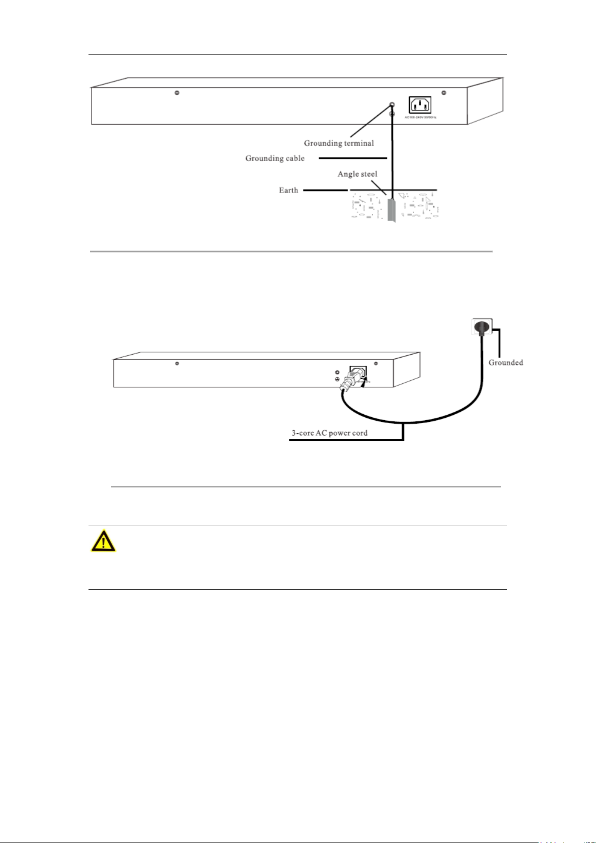
Without grounding bar
If there is no ground bar but earth nearby and the grounding body is allowed to be buried, follow below
steps:
1) Bury an angle steel or steel pipe (≥0.5m) into the mud land.
2) Weld one end of the grounding cable to the angle steel or steel pipe and embalm the welding point.
3) Connect the other end of the grounding cable to the grounding terminal and fix the screw.
15
Page 17
User Manual of Network Video Recorder
Figure 2.7 Ground with an angle steel
If both ground bar and the conditions for burying the grounding body are not available, an AC-powered
Ethernet switch can be grounded using the PE (Protecting Earth) wire of the AC power supply.
Figure 2.8 Ground with 3-core AC power cord
Cautions
Make sure that the PE wire of the AC power supply has been well grounded at the side of the power distribution
room or AC power supply transformer.
16
Page 18

User Manual of Network Video Recorder
Chapter 3 Physical Connection
3.1 Connect to RJ45 Ports
Connect the switch to a remote device with Ethernet cable via RJ45 port. G1 and G2 are uplink ports. Ports
1-16/24 support IEEE 802.3af and IEEE 802.3at PoE supply, and the PD can be wireless AP, IP phone or IP
camera, etc. By default, PoE features of Ports 1-16/24 are enabled.
Figure 3.1 RJ45 port connection
Note that:
1. Cat 5e or better Ethernet cable is recommended. As each RJ45 port supports MDI/MDIX auto-negotiating,
either parallel or crossover cable is available.
2. The device supports dynamic PoE supply. Namely, the device will power the PD properly and automatically.
17
Page 19

User Manual of Network Video Recorder
3.2 Connect to SFP Combo
1) Insert your optical module into the SFP port (G1-F/G2-F).
Figure 3.2 Insert optical module
2) Insert the remote optical fiber to the mod ule correctly. (RX fiber into the port labeled RX on the module; and
TX fiber into the TX)
Figure 3.3 Insert optical fiber
18
Page 20

User Manual of Network Video Recorder
3.3 Check the Cabling
Once installation i s completed, check the cabling of the device as the following:
The operating power supply should accord with rated input standard.
Ports cablings and grounding cable are correctly connected.
If there is outdoor cabling, connect a lightning protector to the cable before you plug the cable into the port.
Figure 3.4 Lightning protector connection
① Ethernet cable ③ Grounding terminal ⑤ L i g htni ng pr otector
② Grounding cable ④ Outdoor cabling
3.4 Connect to Power Supply
Please use the included power cord for power supply.
Figure 3.5 Power connection
19
Page 21

User Manual of Network Video Recorder
Appendix Technical Specifications
Item DS-3E0326P-E DS-3E0318P-E
10/100Mbps RJ45 24 16
Interfaces
Performance
PoE Power
Extend Mode Supported
Lightning-proof
Ranking
10/100/1000Mbps RJ45 2 (G1, G2) 2 (G1, G2)
1000Mbps SFP 2 (G1-F, G2-F) 2 (G1-F, G2-F)
High priority ports 1-8 1-8
Store-and-forward Supported
MAC Table 4k 4k
MAC Learning Auto-learning/ Auto-aging
Switching Capacity 8.8Gbps 7.2Gbps
PoE standard IEEE 802.3af, IEEE 802.3at
PoE Powering Mode
PoE Port 1-24 1-16
Max Port Output 30W 30W
Max Total Output 370W 230W
RJ45 port
lightning proof
Power source
lightning proof
Supports 8 pins powering, which means pins 1,2,3,6 and pins
4,5,7,8 can power simultaneously
4KV
6KV
Power Input 100-240V A C, 50/60Hz
Physical
Environment
Transmission Speed
Transmission Medium
Network Standard
Operating
Environment
Storage
Environment
Temperature: 0℃-40℃
Humidity: 10%-90% RH non-condensing
Temperature: -40℃-70℃
Humidity: 5%-90% RH non-condensing
Ethernet: 10Mbps (Half Duplex) / 20Mbps (Full Duplex)
Fast Ethernet: 100Mbps (Half Duplex) / 200Mbps (Full Duplex)
Gigabit Ethernet: 2000Mbps (Full Duplex)
Ethernet: Cat 3 or better UTP/STP
Fast Ethernet: Cat 5 or bet ter UTP/STP
Gigabit Ethernet: Recommended to use Cat 5e or Cat 6 UTP/STP
1000Base-SX: MMF (Multimode optical fiber)
1000Base-LX: MMF (Multimode optical fiber) or SMF (Single
Mode Fiber)
IEEE 802.3, IEEE 802.3u, IEEE802.3ab, IEEE 802.3af,
IEEE802.3at, IEEE 802.3x, IEEE802.3z
20
 Loading...