

Page 1
TURBO HD
1080P Dome Camera
User Manual
Regulatory Information
FCC Information
FCC compliance: This equipment has been
tested and found to comply with the limits for a
dig ital de vice, p ursuan t to part 1 5 of the F CC
Rul es. The se limi ts are de signe d to provi de
reasonable protection against harmful
interference when the equipment is operated in
a commercial environment. This equipment
gen erates , uses, a nd can rad iate rad io
frequency energy and, if not installed and used
in accordance with the instruction manual, may
cau se harm ful inte rferen ce to rad io
communications. Operation of this equipment in
a residential area is likely to cause harmful
interference in which case the user will be
req uired to c orrec t the inte rferen ce at his o wn
expense.
FCC Conditions
This device complies with part 15 of the FCC
Rules. Operation is subject to the following two
conditions:
1. Th is devi ce may not c ause ha rmful
interference.
2. Th is devi ce must a ccept an y inter ferenc e
received, including interference that may
cause undesired operation.
EU Conformity Statement
upon the purchase of equivalent new equipment,
or dispose of it at designated collection points.
For more information see:
www.recyclethis.info.
2006/66/EC (battery directive):
This product contains a battery that
cannot be disposed of as unsorted
municipal waste in the European
Union.
See the product documentation for specific
batt ery inf ormati on. Th e batter y is marke d with
thi s symbo l, whic h may incl ude let tering t o
ind icate ca dmium ( Cd), le ad (Pb) , or merc ury (Hg ).
UD.6L0201D1818A01
2012/19/EU (WEE E directive):
Products marked with this symbol
cannot be disposed of as unsorted
municipal waste in the European
Union. For proper recycling, return
this product to your local supplier
This product and - if applicable - the
supplied accessories too are marked
wit h "CE " and com ply ther efore wi th
the applicable harmonized European
stan dards l isted un der the L ow Volta ge Direc tive
2006/95/EC, the EMC Directive 2004/108/EC,
the R oHS Di recti ve 2011 /65/E U.
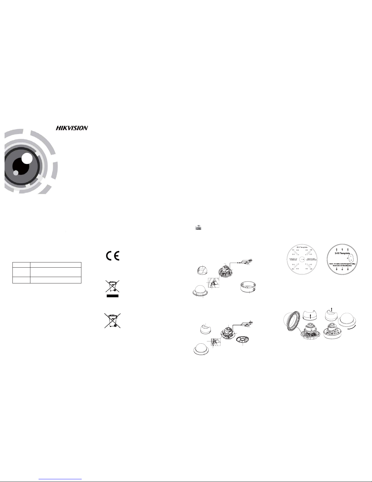
1.2 Overview
1.2 .1 Over view of Ty pe I Came ra
1.2 .2 Over view of Ty pe Came ra
II
1 Introduction
1.1 Product Features
This camera adopts new generation sensor with
high sensitivity and advanced circuit board design
technology. It possesses the features of high
resolution, low distortion, and low noise, etc. It is
extremely suitable for supervisory system and
image processing system.
The main features are as follows:
l Ple ase make s ure tha t the dev ice in th e packag e
is in g ood con ditio n and all t he asse mbly pa rts
are i nclud ed.
l Make s ure tha t all the re lated e quipm ent is
power-off during the installation.
l Check the specification of the products for the
installation environment.
l Check whether the power supply is matched
wit h your po wer outp ut to avo id dama ge.
l Please make sure the wall is strong enough to
withstand three times the weight of the camera
and the mounting.
l If th e wall is t he ceme nt wall, y ou need t o inser t
exp ansio n screws b efore yo u instal l the cam era.
If the wall is the wooden wall, you can use
sel f-tapp ing scr ew to secu re the ca mera.
l If the product does not function properly,
please contact your dealer or the nearest
ser vice ce nter. Do not d isass emble t he came ra
for repair or maintenance by yourself.
For p roper re cycli ng, retu rn the ba ttery t o your
supplier or to a designated collection point. For
more information see: www.recyclethis.info.
2 Installation
Before you start:
Thank you for purchasing our product. If there
are a ny quest ions, o r reque sts, ple ase do no t
hes itate to c ontact t he deal er.
This manual applies to
Thi s manua l may cont ain sev eral tec hnica l
incorrect places or printing errors, and the
content is subject to change without notice.
The u pdate s will be ad ded to th e new ver sion of
this manual. We will readily improve or update
the products or procedures described in the
manual.
0100001050521
Fig ure 1-1 O vervi ew of Type I Ca mera
Fig ure 1-2 O vervi ew of Type Cam eraII
Privacy Notice
Surveillance laws vary by jurisdiction. Check all
relevant laws in your jurisdiction before using
this product for surveillance purposes to ensure
that your use of this product conforms.
Please refer to the product specification for
camera parameters and functions.
Type
Type
Type
I
II
Model
DS-2CE 56D5T-AIRZ
DS-2CE 56D5T-AVPIR3Z
DS-2CE 56D5T-AVPIR3Z H
HD Video Cable
CVBS Cable
Lens
AC 24V Powe r Cable
Black Liner
Bubble
DIP Switch
Auxiliary Video Output
Base Plate
Menu Joystick
2.1 Ceiling Mounting
Steps:
1.Dr ill the s crew ho les and t he cable h ole on th e
ceiling according to the supplied drill template.
Figure 2-1 The Drill Template
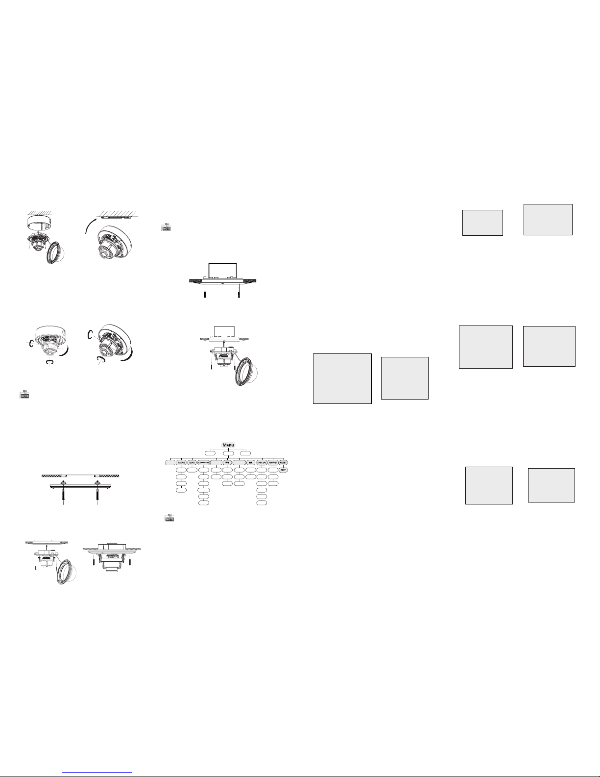
2 Loosen the screws on the bubble of type 1
.
cam era /rot ate the bu bble of t ype2 ca mera to
rem ove the bu bble an d the bla ck line r.
Figure 2-2 Remove the Bubble
Type I:
Type I :I
Type I :I
Type I:
3.Att ach the b ack box of t ype 1 cam era /ba se plate
of type2 camera to the ceiling and secure them
with supplied self-tapping screws.
4.Route the cables through the cable hole.
Menu Joystick
CVBSCable
Black Liner
Lens
Bubble
Auxiliary Video Output
DIP Switch
Base Plate
HD Video Cable
AC2 4V Powe r Cable
l
High performance CMOS sensor and high
resolution bring high-quality image;
l
Turbo HD output, up to 1080P resolution;
l
2.8 – 12mm motorized vari-focal lens;
l
OSD menu, parameters are configurable;
l
Support Day/Night switch;
l
SMART IR mode;
l
Support UTC function;
Built-in heater.
l
The built-in heater function varies according to
different models.
Industry Canada ICES-003 Compliance
This device meets the CAN IC ES-3 (A)/NMB-3(A)
standards requirements.
Page 2
3 Menu Operation
Figure 3-1 Main Menu
DAY&NIGHT
BACKLIGHT
INDOOR
OUTDOOR
INDOOR1
LOWLIGHT
MANUAL SHUTTER
AGC
SENS-UP
BRIGHTNESS
D-WDR
DEFOG
BLC
HSBLC
ATW
AWC-SET
MANUAL
COLOR
B/W
EXT
2DNR
3DNR
CAM
TITLE
D-EFFECT
MOTION
PRIVACY
LAUGUAGE
DEFECT
VERSION
SHARPNESS
MONITOR
LSC
VIDEO.
OUT
SETUP
SMART
FOCUS
You can call the menu and adjust the camera
parameters with a coaxial camera controller
(pu rchas e separa tely) . You ca n also ca ll the me nu
with supported TVI DVR.
3.1 VIDEO.O UT
PAL or NTSC is selectable .
3.2 LANGUA GE
English, Japanese, CHN1, CHN2, Korean, German,
French, Italian, Spanish, Polish, etc., are selectable.
3.3SETUP
3.3.2 SCENE
You can select indoor, outdoor, indoor 1 and low
-li ght as th e worki ng envir onmen ts.
3.3.3 LENS
The c amera is e quipp ed with 2 .8-12 mm moto rized
vari-focal lens.
3.3.4 EXPOSURE
EXPOSURE
1. SHUTTER AUTO
2. AGC OFF
3. SENS-UP ---
4. BRIGHTNESS ---|------ 40
5. DEFOG OFF
6. D-WDR OFF
7. RETURN RET
Figure 3-2 Exposure
SHUTTER: AUTO,1/25, 1/50, FLK, 1/200, 1/400,
1/1 k, 1/2k , 1/5k, 1 /10k, 1 /50k, x 2, x4, x6 , x8, x10 ,
and x15 are selectable.
: You can s et the A GC val ue from 0 t o 15.AGC
: You can s et the S ENS -UP t o OFF o r AUT O.SENS-UP
: You can s et the br ightn ess valu eBRIGHTNESS
fro m 1 to 100.
: You can s et the de fog func tion as ON t oDEFOG
enable the function. Position, size, and the defog
gradation are configurable.
You can s et the D- WDR a s ON or O FF.D-WDR :
3.3.5 Backlight
Backlight Compensation (BLC):
Set t he gain of BL C as Hig h, Midd le, or Lo w.-GAIN:
Press the up/down/left/right button to-AREA:
define the BLC position and size. Select RET or
AG AIN to go ba ck the B LC me nu or re-d efine t he
BLC area.
Restore theB LC settings to the default.-Default:
HSBLC:Select an HS BLC area. Set the DISP LAY
status as ON. Press the up/down/left/right button
to de fine th e area pos ition a nd size . Set the H SB LC
LEV EL from 0 to 100. Select ALL DAY or Night for the
HSB LC mode. Set the BLACK MA SK status as ON or
OFF.
HSBLC
1. SELECT AREA1
2. DISPLAY ON 8
3. LEVEL ---|------40
4. MODE ALL DAY
5. BLACK MASK ON
6. DEFAULT 8
7. RETURN RET
Figure 3-3 HSBLC
3.3.6 White Balance (WB)
MAN UAL, ATW (Auto-tracking White Balance),
AWC→SE T are selectable.
3.3 .7 Day & Ni ght
Color, B/W, and EXT are selectable for DAYand
NIGHT switches.
3.3.8 NR
: You can s et 2D NR stat us as ON or O FF.2D NR
: Set the Smart NR status as ON and adjust3D NR
the 3 D smart N R sen sitiv ity rang es from 0 to 1 00.
Set t he 3D NR LE VEL rang es from 0 t o 100. Set t he
2D&3D NR
1. 2DNR OFF
2. 3DNR ON
8
3. RETURN RET
3D NR
1. SMART NR ON
8
2. LEVEL ------ |--8 0
3. START. AGC -|--------10
4. END. AGC -|--------10
5. RETURN RET
Figure 3-4 NR
Fig ure 3-5 3 D NR
3.3.9 SPECIA L
Edi t the came ra titl e on this s ectio n.Camera Title:
D-effect:
Set the freeze function as ON orO FF.-FREEZE:
OFF, MIRROR, V-FLIP, andROTATEare-MIRROR:
selectable for mirror.
Define the zoom area by configuring-D-ZOOM:
the position fromPAN & TI LT.
The D-Zoom area, sensitivity-SMART D-ZOOM:
and time are configurable.
Set theNEG IMAGE asON or OFF.-NEG.IMAGE:
SPECIAL
1. CAM TITLE ON 8
2. D-DFFECT 8
3. MOTION OFF
4. PRIVACY OFF
5. DEFECT
8
6. RETURN RET
Figure 3-6 Special
MOTION
1. SELECT AREA 1
2. DISPLAY ON8
3. SENSITIVITY ----|---- 30
4. MOTION VIEW ON
5. DEFAULT 8
6. RETURN RET
Fig ure 3-7 M otion D etecti on
Motion: Select aM OTION area. Set the DISPLAY
status as ON orO FF. Press the up/down/left/right
but ton to def ine the p ositi on and si ze of the a rea.
Set t he SE NSI TIV IT Y from 0 to 6 0. Set th e MOT ION
VIEW status asON or OFF.
Privacy: Select aP RIVACY area. Set the DISPLAY
status as INV, MOSAIC, COLORor OFF. Press the
up/down/left/right button to define the position
and s ize of the a rea.
Defect: LIVEDPC, STATIC DPC and BlackDPC are
adjustable in this section.
PRIVACY
1. SELECT AREA 1
2. DISPLAY MOSAIC
8
3. COLOR 10
4. TRANS. 1
5. DEFAULT
8
6. RETURN RET
ADJUST
1. SHARPNESS
--------|15
2. MONITOR LCD8
3. LSC OFF
4. RETURN RET
3.3.10 ADJUST
: Adjust the sharpness from 0 to 15.Sharpness
: Monitor CRT, and Monitor LCD areMonitor
selectable.
: Set t he LS C statu s as ON or OF F.LSC
3.3.11 RESET
Res et all the s ettin gs to the d efault .
3.3.12 EXIT
Pre ss OK to e xit the m enu.
START. AGC level as the threshold to enableA GC,
and s et the E ND. A GC lev el as the t hresh old to
disable AGC.
Figure 3-8 Privacy Mask
Figure 3-9 Adjust
3.3.1 SMART FOC US
Move the joystick to adjust the camera lens by the
FOCUS+,FOCUS-, ZOOM+ andZOOM-. The smart
focus value turns higher when the focusing
effe ctive ness tu rns bett er. The valu e range i s 0~99.
Steps:
1.Dr ill the s crew ho les and t he cable h ole in th e
ceiling according to the supplied drill template.
2.Sc rew the b olts th rough th e mount b y align ing
wit h the 2 bol t holes . Fit the t oggle s onto the b olts.
3.P ush the t wo togg le bolt s throug h the two s crew
holes on the ceiling. Rotate the bolt till the toggle
holds the ceiling tightly.
2.2 In-ceiling Mounting
Fig ure 2-5 I nstall t he Moun t
4.Route and connect the corresponding cables.
5.Fix the camera to the in-ceiling mount with the
supplied screws.
Figure 2-3 Fix the Camera to the Ceiling
6. Connect the corresponding cables.
7. Ad just th e camera a ccord ing to the f igure b elow
to get a n optim um angl e.
8. Fi t the bla ck line r on the ca mera and t ighte n the
screws on the bubble of type 1 camera or rotate the
bub ble of ty pe 2 came ra to comp lete.
Fig ure 2-4 3 -axis Ad justm ent
You need to purchase an in-ceiling mount separately
if you adopt in-celling mounting.
Type I:
Type I :IType I :IType I :I
P Direction
R Direction
T Direction
Type I:
T Direction
R Direction
P Direction
Type I :I
5.Align the camera with the back box/base plate,
and t ighte n the set sc rews to s ecure th e camer a
with the back box/base plate.
Type I:
Type I :I
Fig ure 2-6 F ix the Ca mera to th e Mount
Fig ure 2-8 F ix the Ca mera to th e Gang Box
6. Repeat steps 6-8 of the Ceiling Mounting section
to complete the installation.
2.3 In-ceiling Mounting with
Gang Box
Only the type 1 camera supports in-ceiling
mounting with gang box.
1.Repeat steps 2-4 of the In-ceiling Mounting
section to secure the in-ceiling mount (supplied)
to the gang box.
Fig ure 2-7 I nstall t he Moun t
2.Route and connect the corresponding cables.
3.A lign th e camera w ith the g ang box , and tig hten
the s crews to s ecure t he came ra with th e gang box ..
4. Repeat steps 6-8 of the Ceiling Mounting section
to complete the installation.
0°~75°
0°~355°
0°~355°
0°~ 340°
0°
~
355°
0°~ 75°
 Loading...