

Page 1
Bullet Camera
User Manual
UD.6L0201D0170A01
www.hi kv is io n. com
Thank you for purchasing our pro du ct . If t he re
are a ny questions, or re qu ests, please do not
hesitate to co ntact the dealer.
This manual applies to
Type
Ⅰ
Ⅱ
Ⅲ
Ⅳ
This manual may contain seve ral tec hn ic al
incor re ct places or printing errors, and the
con tent is subject to change w it ho ut n ot ic e.
The updat es w il l be a dd ed to the new versi on o f
this manual. We will rea di ly i mp rove or updat e
the pro du ct s or p rocedures described in the
manual.
DISCLAIMER STATEMENT
Underwriters Laborat or ie s In c. ( ”UL”) has not
tes ted the perfo rm an ce o r reliability of the
security or signaling aspects of this pro du ct .
0100001030115
Model
DS-2C E1 58 2P(N)-IR
DS-2C E1 5C 2P(N)-IR
DS-2C E1 68 2P(N)-IT3
DS-2C E1 6C 2P(N)-IT3
DS-2C E1 68 2P(N)-IT5
DS-2C E1 6C 2P(N)-IT5
DS-2C E1 58 2P(N)-VFIR3
UL has only tes ted for f ire, shock or casualty
hazards as outlined in Ul’s Sta nd ard(s) for Sa fety,
UL60950-1.
UL Certificat io n do es n ot
perfo rm an ce o r reliability of the
signaling aspects of this pro du ct U L MA KES NO
REPRESE NTATIONS, WARRANTIES OR
CERTI FI CATIONS WHATSOEVER REGARDING
THE PERFO RM AN CE O R RE LI AB IL IT Y OF A NY
SEC UR IT Y OR S IG NA LI NG R EL ATED FUNCTIONS
OF THIS PRO DU CT.
cov er the
security or
Regulatory Information
FCC Information
FCC com pl ia nc e: T hi s eq ui pm ent has been
tes ted and fou nd t o comply with the limits fo r a
digital d ev ic e, p ursuant to pa rt 1 5 of t he FCC
Rules. These limits are d es ig ne d to provid e
rea so na bl e protection agai nst harmful
int er feren ce w he n th e eq ui pm ent is operated in
a com me rcial environ me nt. This equipment
gen erates, uses, a nd c an radiate radio
fre qu en cy e ne rgy and, if not insta ll ed a nd u se d
in acco rd an ce with the instruction manual, may
cau se h ar mf ul i nterference to rad io
com mu ni cations. Operat io n of t hi s eq ui pm ent in
a res id ential area is likely to cause harmf ul
int er feren ce i n wh ic h case the user will be
req ui red to correc t th e interfe rence at his own
exp en se .
FCC Con di ti on s
This device com pl ie s wi th p ar t 15 o f th e FCC
Rules. Operation is subject to the fol lowing two
con di ti on s:
1. This devic e may not cause harmful
int er feren ce .
2. This devic e mu st a cc ept any int er feren ce
rec ei ved, including interference that m ay
cau se u nd es ir ed operat io n.
EU Conformity Statement
This prod uc t an d - if a pp li cable -
the supplied accessories to o are
marked with "CE" and comply
there fore wi th t he a pp li cable harmonized
Europ ea n standards l is ted under the Low Voltage
Direc ti ve 2006/95/EC, the EMC Dire ct ive 2004/
108/EC.
2002/96/EC (W EE E di rective):
Pro du ct s ma rked with this symbol
can no t be d is po se d of a s un so rt ed
mu ni c ip al wa st e in th e Eur op e an
up on t h e pu rch as e o f eq uiv al ent n ew e q ui pme nt ,
or d is p os e of it a t de s ig nat ed c o ll ect ion p oi n ts .
For mo re i n fo rma tio n se e:
www.recyclethis.info.
See the pro du ct d oc um entation for specific
bat tery info rm at ion. The batter y is m ar ked with
this sy mb ol , wh ic h may include lettering to
indicate cadmium (Cd), lead (Pb), or mercu ry ( Hg ).
For p roper recyc li ng , return the batter y to your
supplier or to a de si gn ated collection point . For
more in formation s ee :
www.recyclethis.info.
Un io n . Fo r pr ope r rec yc lin g, r e tu rn
th is p r od uct t o yo ur lo cal s up p li er
2006/66/EC (b attery dire ct ive):
This prod uc t contains a battery
that ca nn ot b e di sp os ed o f as
unsorte d mu ni ci pa l waste in the
Europ ea n Un io n.
1 Introduction
1.1 Product Features
This series of ca me ra adopts new generation
sensor with high sensitivity and adva nc ed
circu it d es ig n technology. It features h ig h
res ol ut io n, l ow i ma ge distorti on a nd l ow n oi se
features, et c. , which makes i t su itable for
surveillance syste m an d im ag e processing
system.
●High-perfor ma nc e sensor and high resolution
bring high-quality image
●IR LED enables the day/ n ig ht s ur ve illance
●IR cut filter a ut o switch
●ATW brings high color ren di ti on
●Ingre ss p rotection:IP66
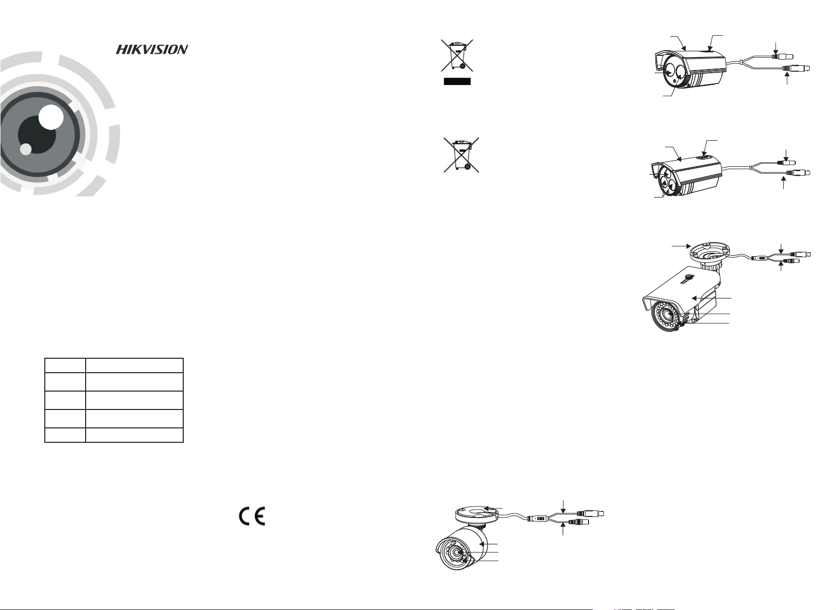
1.2 Overview
Vi deo C abl e
Moun ti ng B as e
Su n Shi eld
Le ns
IR L ED
Figure 1- 1 Over vi ew of Type Ⅰ Camera
Powe r Cab l e
Sun Shield
Lens
IR
LED
Figure 1- 2 Over vi ew of Type Ⅱ Camera
Sun Shield
Lens
IR LED
Figure 1- 3 Over vi ew of Type Ⅲ Camera
Mount in g Ba se
Figure 1- 4 Over vi ew of Type Ⅳ Camera
Adjusta ble Screw
Power Cable
Video Cable
Adjusta ble Screw
Power Cable
Video Cable
Video Cable
Power Cable
Sun Shield
Lens
IR LED
2 Installation
Before you start:
●Make sure that a ll t he related equipment is
power -o ff d ur ing the installat io n.
●Check the specifica ti on o f th e products fo r th e
installation environment.
●Check wheth er t he p ow er s up pl y is m atched
with yo ur A C ou tl et to avo id d am age.
●If the prod uc t do es n ot f un ct io n properly,
please co ntact your dealer or the nearest
service cente r. Do not disassemble the
cam era for rep ai r or m ai ntenance by
you rself.
●Please make sure that th e ce il in g or t he wall
is st rong enough to withstan d 3 ti me s th e
wei gh t of t he camera.
Page 2
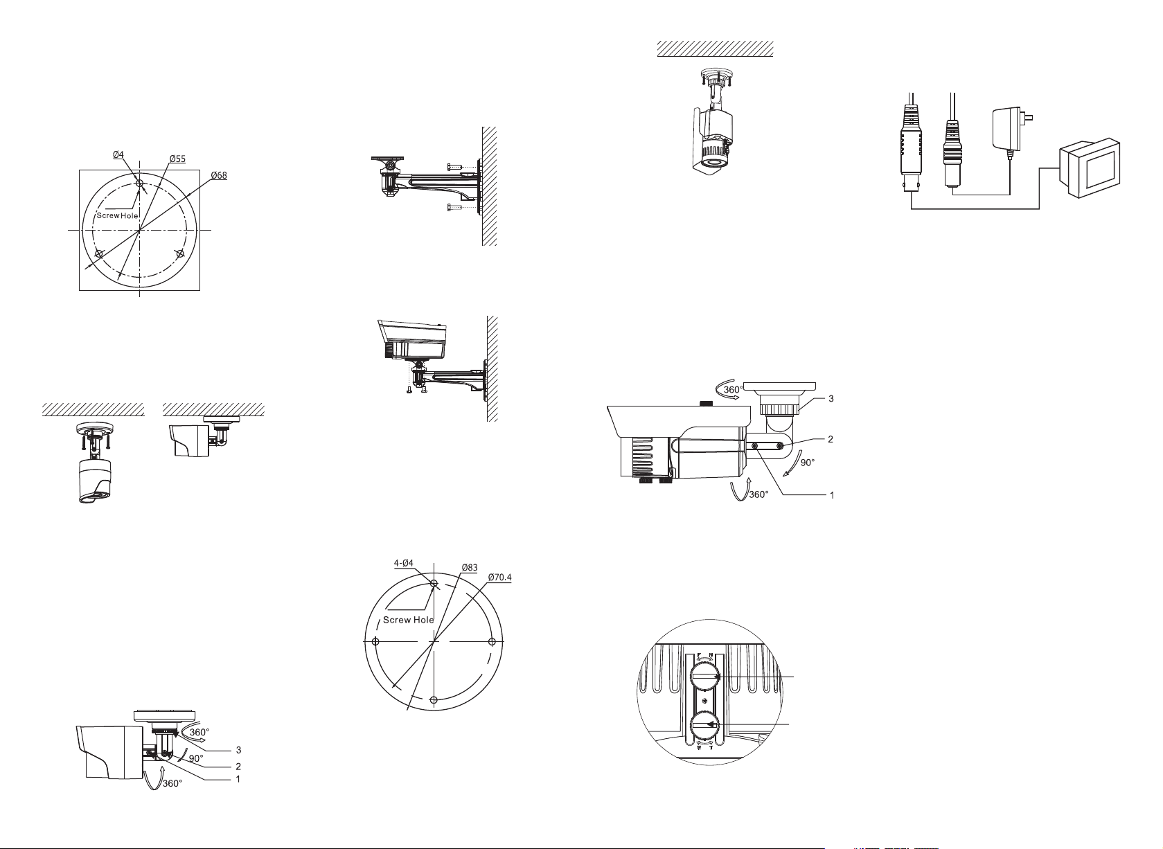
2.1 Ceiling Mounting for Type I
Camera
Ste ps :
1.Drill the scre w ho les and th e cable hole on the
ceiling according to the supplied drill temp la te.
Figure 2- 1 Dr il l Temp late
2.Ro ute the cables to t he c ab le h ol e an d connect
the cor re sp on di ng p ower cable and video ca bl e.
3.Secure t he camera to th e ce il in g wi th t he
self-ta pp in g sc rews.
2.2 Ceiling Mounting for Type II/ III
Camera
Ste ps :
1.Secure t he m ou nt to the wall with the screws.
Figure 2- 4 Se cu re the Mount
2.Secure t he camera to th e mo un t wi th t he
screws to complete t he i nstallati on .
Figure 2- 5 Se cu re the Camera
Figure 2- 7 Se cu re the Camera t o th e Ce il in g
4.Adjust t he l en s.
1).Loosen the panning ta bl e to adjust the
panning position (0°to 360°).
2).Tight en t he p an ni ng table.
3).Loosen the tilting lock screw to adjust the
tilting position (0° to 90°) .
4).Tight en t he t ilting lock screw.
5).Loosen the ro tation lock screw to adjust the
azimuth angle of the image (0° to 360°).
6).Tight en t he rotati on l oc k sc rew.
2.4 Power Supply
Figure 2- 10 T he Powe Cable & the Vid eo C ab le
Note:
Please make sure that th e po wer adapter is
com pa ti bl e wi th t he camera, an d th e standard
power s up pl y is 1 2V D C. P le as e refer to the
tec hn ic al s pe ci fi cation fo r mo re info rm ation.
Figure 2- 2 Se cu re the Camera t o th e Ce il in g
4.Adjust t he L en s.
1).Loosen the panning ta bl e to adjust the
panning position (0 to 36 0 .
2).Tight en t he p an ni ng table.
3).Loosen the tilting lock screw to adjust the
tilting position (0° to 90°).
4).Tight en t he t ilting lock screw.
5).Loosen the ro tation lock screw to adjust the
azimuth angle of the image (0° to 36 0°).
6).Tight en t he rotati on l oc k sc rew.
Figure 2- 3 Ad ju st the Lens
° °)
2.3 Ceiling Mounting for Type IV
Camera
Ste ps :
1.Drill the scre ws holes and the cable hole on the
ceiling according to the supplied drill temp la te.
Figure 2- 6 Dr il l Temp late
2.Ro ute the cables to t he c ab le h ol e an d connect
the cor re sp on di ng cables.
3.Secure t he camera to th e ce il in g wi th t he
self-ta pp in g sc rews.
Figure 2- 8 Le ns A dj ustment
5.Adjust t he Zoom and the Focus
1).Output the image to t he m on itor.
2).Adjust th e Zoom Screw and Fo cu s Sc rew till
you g et the optimum sur veillance angle.
Zoom
Focus
Figure 2- 9 Zoom and Focus Adjust me nt
 Loading...