

TURBO HD
720P Turret &Bullet Camera
User Manual
UD.6L0201D1454A01
Thank you for purchasing our product. If there
are a ny qu est ions, or requests, p lease do not
hesitate to c ontact t he dealer.
This manual applies to DS-2CE56C5T-VFIT3 and
DS-2CE16C5T-(A)VFIR3.
This manua l may contain s everal technical
incorrect places or printing errors, and the
content is subject to change without notice.
The updates wil l be ad ded to the new version of
this manual. We will readily improve or update
the products or procedures described in the
manual.
DISCLAIMER STATEMENT
Underwriters Laboratories Inc. (”UL” has not)
tested the performance or reliability of the
security or signaling aspects of this product.
UL has only tested for fire, shock or casu alty
hazard s as outline d in Ul’s Sta ndard(s) fo r Safety,
UL60950- 1. UL Certif icatio n does not cover the
performance or reliability of the security or
signaling aspects of this product. UL MAKES NO
REPRESENTATIONS, WARRANTIES OR
CERTIFICATIONS WHATSOEVER REGARDING
0100001040603
THE PERFORMANCE OR RELIABILITY OF ANY
SECURITY OR SIGNALING RELATED FUNCTIONS
OF THIS PRODUCT.
Regulatory Information
FCC Information
FCC compliance: This equipment has been
tested and found to comply with the limits for a
digital devic e, pu rsu ant t o part 15 of the FCC
Rules. The se limits are des ign ed to prov ide
reasonable protection against harmful
interference when the equipment is operated in
a commercial environment. This equipment
gen erates , use s, and can radiate radi o
frequency energy and, if not installed and used
in accordance with t he instructio n manual, may
cau se harmful i nterference to ra dio
communications. Operation of this equipment in
a residential area is likely to cause harmful
interference in which case the user will be
req uired to c orrect the interfer enc e at his own
expense.
FCC Conditions
This device complies with part 15 of the FCC
Rules. Operation is subject to the following two
conditions:
1. This devi ce may not c aus e harmful
interference.
2. This devi ce mu st accept any inte rfe ren ce
received, including interference that may
cause undesired operation.
EU Conformity Statement
This product an d - if applicable the supplied accessories too are
therefore with the applicable harmonized
European standards listed under the Low Vo lta ge
Directive 2006/9 5/EC, the EMC Direct ive 2 004/
108/EC, the RoHS Directive 2011/65/EU.
upon the purchase of equivalent new equipment,
or dispose of it at designated collection points.
For more information see:www.recyclethis.info.
See the product documentation for specific
bat ter y inform ati on. The battery is mar ked with
this symbol, wh ich m ay in clude lettering to
indicate ca dmium (Cd) , lead (Pb), o r mercury (Hg).
For p rop er re cyc ling, return th e batter y to your
supplier or to a designated collection point. For
more information see:www.recyclethis.info.
marked w ith "CE" and comp ly
2012/19/EC (WEEE directive):
Products marked with this symbol
cannot be disposed of as unsorted
municipal waste in the European
Union. For proper recycling, return
this product to your local supplier
2006/66/EC (battery directive):
This product contains a battery
that cannot be disposed of as
unsorted municipal waste in the
European Union.
1 Introduction
1.1 Product Features
This camera adopts new generation sensor with
high sensitivity and advanced circuit board design
technology. It possesses the features of high
resolution, low distortion, and low noise, etc. It is
extremely suitable for supervisory system and
image processing system.
The main features are as follows:
l
High performance CMOS sensor and high
resolution bring high-quality image;
l
Low illumi nat ion, 0.01 Lu x @ (F1 .2, AGC ON),
0 Lux with IR;
l
Support IR cut filter with auto switch;
l
OSD menu, pa rameters are configurable;
l
Support auto white balance, auto gain control,
electronic shutter control and internal
synchronization;
l
Advanced Engineering Design and patent
universal adjustable structure provides
convenient adjustment and high reliability;
lSMART IR mode;
l
Unit transmission control;
l
Advanced 3-axis design meets different
installation requirements;
l
Ingress protection: IP66.
1.2 Overview
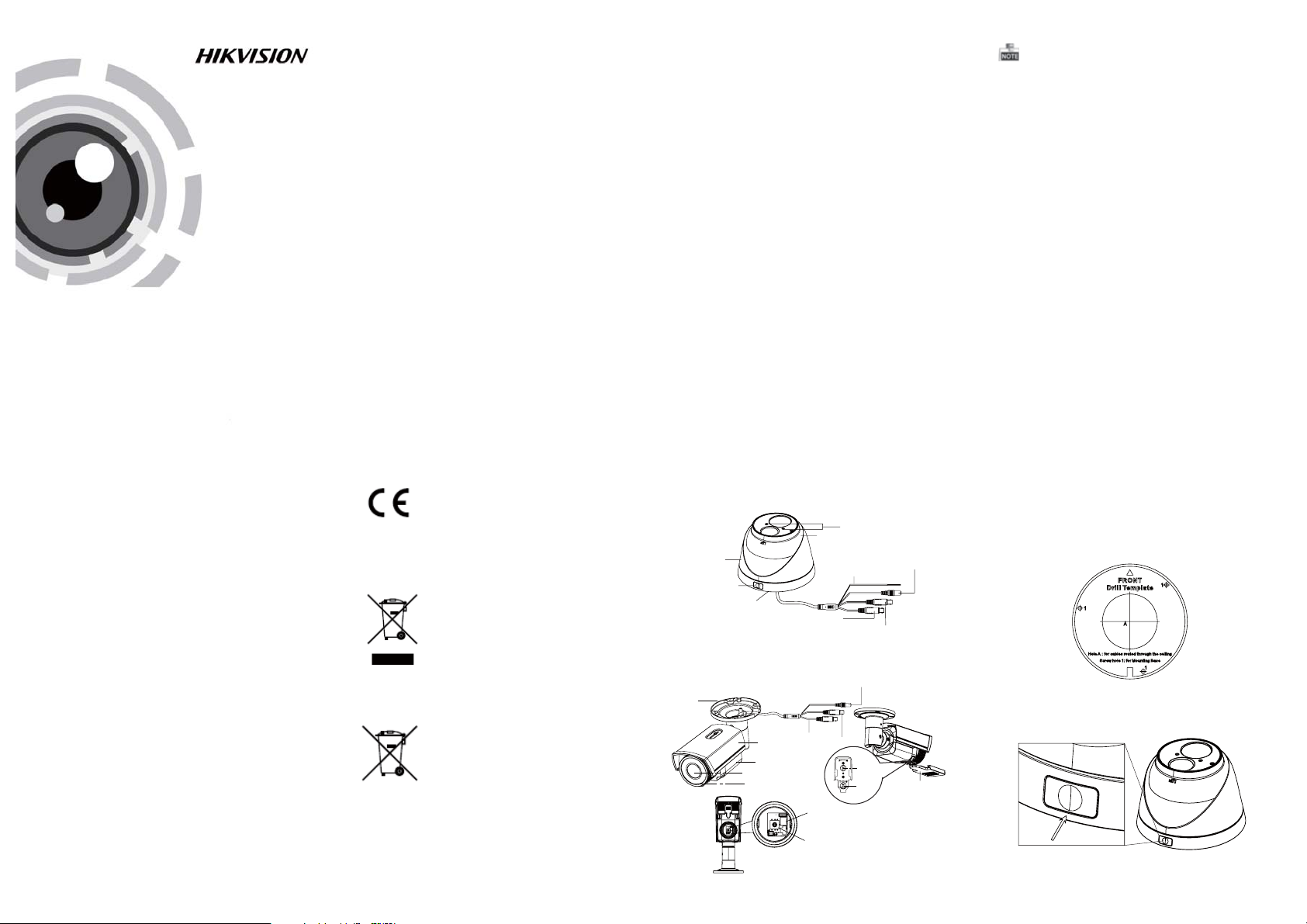
1.2.1 O verview of Type I Camera
Zoom & Focus
Camera
Enclosure
Lock ButtonLock Button
Mounting Base
Switch Cable
CVBS Cable
Figure 1-1 Over vie w of Type I Camera
1.2.2 O verview of Type Camera
Mounting Base
CVBS Cable
Sun Shield
Main Body
Lens
IR LED
Figure 1-2 Over vie w of Type C ameraII
Powe r Cable
HD Video Cable
Dip Switch
Menu Button
Powe r Cable
HD Video Cable
Focus
Zoom
Adjusting Sheet
The HD video o utput mode i s set a s the defa ult.
You can sho rt th e white and bl ack l ine-end of t he
con tro l swi tch c able or press the d ip sw itc h to
switch the mode as CVBS output.
2 Installation
Before you start:
l Please make sure that the device in t he package
is in good condition and all the assembly parts
are i ncluded.
l Make sure that all t he re lat ed eq uipment is
power-off during the installation.
l Check the sp ecification of the p rod ucts for the
installation environment.
l Check whet her t he power supply i s mat ched
with your power outp ut to avoi d damage.
l Please make sure the wall is strong enough to
withstand three times the weight of the camera
and the mounting.
l If the wall is the ce ment wal l, yo u need to inse rt
exp ansion screws before you i nst all t he camera.
If the wall is the wooden wall, you can use
self-tappin g screw to s ecure the camera.
l If the product does not function properly,
please contact your dealer or the nearest
servi ce ce nte r. Do not d isassemb le the camera
for repair or maintenance by yourself.
2.1 Installation of Type CameraI
Steps:
1.Drill the s crew hol es and the cab le ho le on the
ceiling according to the supplied drill template.
Figure 2-1 The Drill Template
.
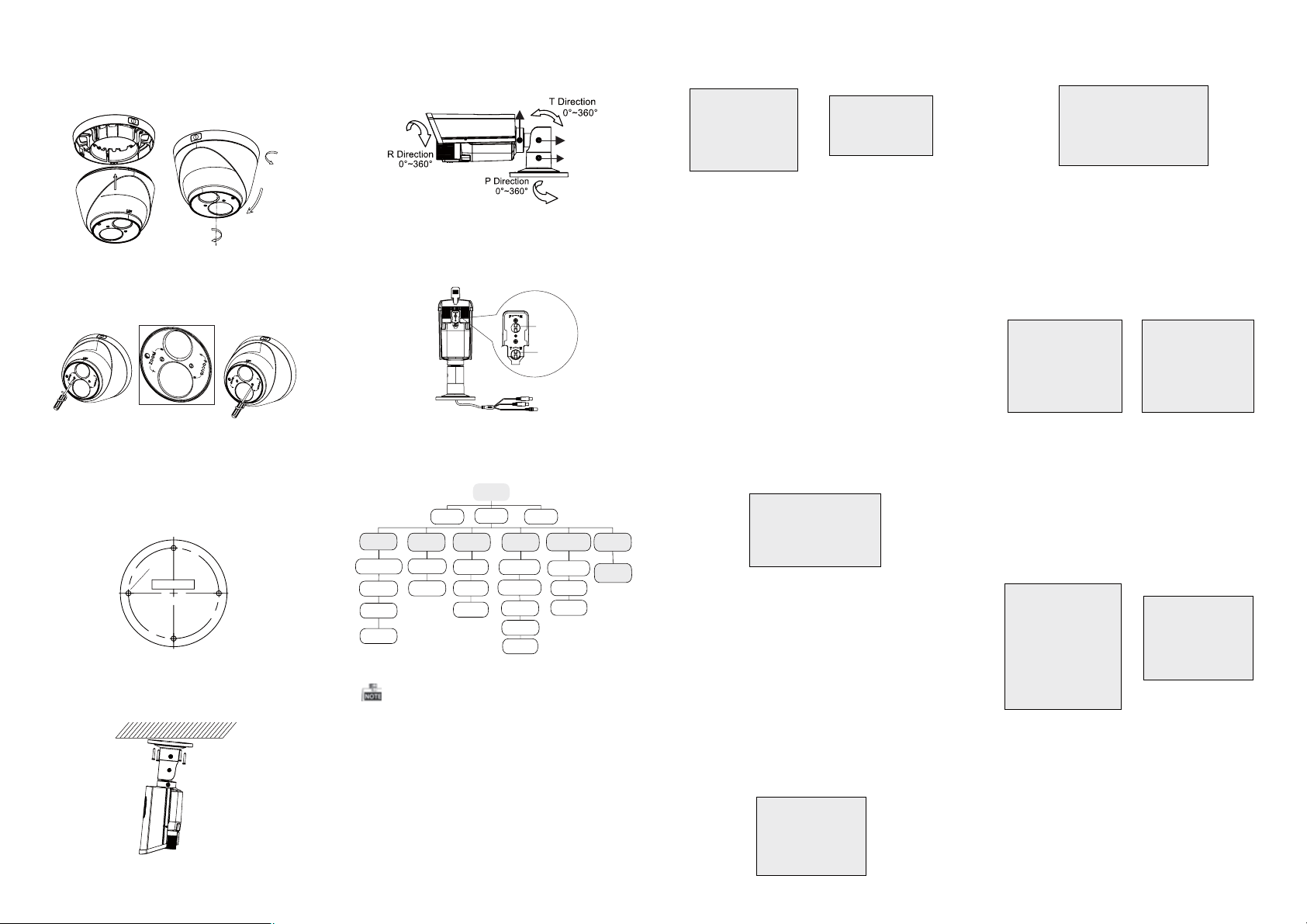
2 Push the loc k button t o dis assemble t he ca mera
from the mounting base.
PUSH
Figure 2-2 Release The Lock Screw
3.Fix the mounting base to the ceiling.
4.Route the cables to the cable hole and connect
the corresponding cables.
5.Secure the camera to the mounting base by
tightening the lock screw.
6.Adjust the camera according to the figure below
to get an op timum angl e.
0 ~360
0 ~75
0~360
Figure 2-3 3-axis Adjustment
7.Use the screwdriver to adjust the ZOOM screw
and the FOCUS screw until you get the o ptimum
image.
Figure 2-4 Zoom and Focus Adjustment
2.2 Installation of Type CameraII
Steps:
1. Drill the screws holes on the ceiling according
to the supplied drill template.
Screw Hole
Tem pl at e
Figure 2-5 The Drill Template
2.Route the corresponding cables.
3.Secure the camera to the ceiling with the self-
tapping Screws
Figure 2-6 Secure the Camera to the Ceiling
4.Connect the corresponding cables.
.
5. Loosen th e T screw, R screw an d P screw
successively and adjust the camera according to
the figure belo w to get an op tim um angle. Ti ght en
the screw after completing the adjustment.
R Screw
T Screw
P Screw
Figure 2-7 3-axis Adjustment
6.Adjust the Zoom Screw and Focus Screw till you
get the optimum surveillance angle.
Focus
Zoom
Figure 2-8 Zoom and Focus Adjustment
3 Menu Operation
MENU
MAIN
VIDEO
STANDARD
WB
DAY
&NIGHT
COLOR
B/W
SMART
AE
BRIGHTNESS
AE MODE
AGC
SENSE UP
AUTO
MANUAL
Figure 3-1 Main Menu
A coaxial camera controller (purchase separately)
is required to select the menu and adjust the
camera parameters.
3.1 AE
Move the cursor to AE, and you can adjust the
image brightn ess b y the , ,BRIGHTNESS AE MODE
AGC SENS-UP, and in this menu .
As shown in Fi gur e 3-2 .
BRIGHTNESS: Set t he brightness valu e fro m
.
1 to 10 t o darken or bri ghten the image.
: Set AE mode as GLOBLE AE , andAE MODE
D-WDR.
MENU
VIDEO
SETTING
CONTRAST
SHARPNESS
COLOR
GAIN
3D NR
MIRROR
LANGUAGE
FUNCTION
DETECTION
MASKING
ZOOM IN
RESET
SAVE
&EXIT
AGC HIGH MIDDLE LOW: , , and can b e set for the
AGC level. Select OFF to disable the AGC.
: Set the SENSE UP value f rom 0 to 16.SENSE UP
AE
1. BRIGHTNESS 1-|--10
2. AE MODE DWDR
3. AGC OFF
4. SENSE UP 0-|---16
5. RETURN 8
Figure 3-2 AE
Figure 3-3 Manu al of WB
MANUAL
1. R GIAN 1-|--10
2. B GAIN 1-|--10
3. RETURN 8
3.2 WB
Move the cursor to WB, and you can set White
Balance mode as and in this menuAUTO MANUAL .
AUTO: white balance is being adjusted
automatically.
: Set the val ueMANUAL R GAIN/B GAIN
fro m 1 to 10 . As shown in Fi gure 3-3.
3.3 DAY & NIGHT
Move the cursor to DAY & NIGHT, and select
COLOR B/W SMART, , or as the DAY & NIGHT m ode.
COLOR: The ima ge is colo red i n day m ode all the
time.
: The image is bl ack & white all the t ime, andB/W
the IR LED turns on in the low-light conditions.
: Select to turn on/off the INFRARED_LAMPSMART
and to set the Smar t IR level f rom 1 to 16.
As shown in Figure 3-4.
SAMRT
1. INFRARED_LAMP OFF
2. SMART IR 0-|--5
3. RETURN 8
Figure 3-4 Smar t Mode of DAY&NI GHT
3.4 Video Setting
Move the cursor to the VIDEO SET TING, a nd press
the menu button to enter the vid eo co nfiguration
int erface . As shown in Fi gure 3-5.
: Set the CONTRAST value from 1 to 10.CONTRAST
val ue from 1 to 1 0.
COLOR GAIN: Set t he co lor gain from 1 to 10.
and . Select to disable the 3D NR.Low OFF
, or .VHV
: Set the edge and detai l sha rpnessSHARPNESS
: Set the 3D NR level as , ,3D NR High Middle
: Set the mirror mode as , ,MIRROR OFF H
VIDEO SETTING
1. CONTRAST 1-|-- 10
2. SHARPNESS
3. COLOR GAIN 1-|--10
4. 3D NR OFF
5. MIRROR OFF
6. RETURN
8
8
Figure 3-5 Vide o Settin gs
3.5 FUNCTION
You can set , , an dDETECTION MASKING ZOOM IN
DETECTION: Set the motion sensitivity as
ent er the motion detect ion AREA menu. As s hown
in Figure 3-7.
are a border. Move the joystick up/do wn and right
/left to set the horizon/ ver tical size an d position .
As shown in Figure 3-8.
1. SENSITIVITY HIGHT
2. AREA NO.0
3. AREA NO.1 8
4. AREA NO.2 8
5. AREA NO.3 8
6. RETURN 8
Figure 3-7 Detection
MASKING: Select a masking back ground color.
Select an AREA to enter the masking AREA menu.
As shown in fi gure 3-9.
up/down and right/left to set the horizon/vertical
size and position.
As shown in Figure 3-10.
1. COLOR WHITE
2. AREA NO.0
3. AREA NO.1 8
4. AREA NO.2 8
5. AREA NO.3 8
6. AREA NO. 8
7. AREA NO.5 8
8. AREA NO.6 8
9. AREA NO.7 8
10.RETURN 8
Figure 3-9 Detection Area
ZOOM IN: The ZOOM IN value can be adjusted from
50 to 100.
LANGUAGE: Chinese and English are selectable.
of the camera in this me nu.LANGUAGE
1. DETECTION
2. MASKING 8
3. ZOOM IN 50-|--100
4. LANGUAGE ENGLISH
5. RETURN
FUNCTION
Figure 3-6 Func tion
, , or . Select an AREA toWEAK LOW MIDDLE HIGH
: Set the status as / . Select a color forAREA OFF ON
DETECTION
8
1. STATUS OFF
2. COLOR
3. HORIZON SIZE 0
4. VERTICAL SIZE 0
5. HORIZON MOVE 0
6. VERTICAL MOVE 0
7. RETURN
Figure 3-8 Detection Area
: Set the statu s as / . Move the joystickAREA OFF ON
MASKING
8
1. STATUS OFF
2. HORIZON SIZE 0
3. VERTICAL SIZE 0
4. HORIZON MOVE 0
5. VERTICAL MOVE 0
6. RETURN
Figure 3-10 Detection
8
8
AREA
WHITE
8
AREA
8
3.6 Reset
Res et al l the settings to the default.
3.7 Save & Exit
Move the cursor to , and press OK toSAVE & R ESE T
save the s ett ings and exit the menu .
 Loading...