

HIKVISION DS-2CD2212-I5, DS-2CD2232-I5, DS-2CD2212-I3, DS-2CD2232-I3, DS-2CD2312-I Installation Manual
...
Installation Manual
www.eyesoniccctv.com

Thank you for purchasing our product. If there are any questions, or requests, please do not hesitate
to contact the dealer.
This manual applies to
Type
Model
20xx Series
DS-2CD2012-I, DS-2CD2032-I
21xx Series
DS-2CD2112-I, DS-2CD2132-I
22xx Series
DS-2CD2212-I5, DS-2CD2232-I5, DS-2CD2212-I3, DS-2CD2232-I3
23xx Series
DS-2CD2312-I, DS-2CD2332-I
26xx Series
DS-2CD2612F-I, DS-2CD2632F-I
27xx Series
DS-2CD2712F-I(S); DS-2CD2732F-I(S)
This manual may contain several technical incorrect places or printing errors, and the content is
subject to change without notice. The updates will be added to the new version of this manual. We
will readily improve or update the products or procedures described in the manual.
DISCLAIMER STATEMENT
“Underwriters Laboratories Inc. (“UL”) has not tested the performance or reliability of the security
or signaling aspects of this product. UL has only tested for fire, shock or casualty hazards as outlined
in UL’s Standard(s) for Safety, UL60950-1. UL Certification does not cover the performance or
reliability of the security or signaling aspects of this product. UL MAKES NO REPRESENTATIONS,
WARRANTIES OR CERTIFICATIONS WHATSOEVER REGARDING THE PERFORMANCE OR RELIABILITY
OF ANY SECURITY OR SIGNALING RELATED FUNCTIONS OF THIS PRODUCT.”
1
www.eyesoniccctv.com

Table of Contents
Chapter 1 Appearance Description ........................................................................................................................ 3
1.1 Appearance Description of Bullet Camera ........................................................................................................... 3
1.1.1 20xx Series Bullet Camera ................................................................................................................................ 3
1.1.2 22xx Series Bullet Camera ................................................................................................................................ 4
1.1.3 26xx Series Bullet Camera ................................................................................................................................ 5
1.2 Appearance Description of Dome Camera ........................................................................................................... 6
1.2.1 21xx Series Dome Camera ................................................................................................................................ 6
1.2.2 27xx Series Dome Camera ................................................................................................................................ 7
1.3 Appearance Description of Turret Camera ........................................................................................................... 8
Chapter 2 Setting the Network Camera over the LAN ........................................................................................... 9
Chapter 3 Accessing via Web Browsers ................................................................................................................ 11
2
www.eyesoniccctv.com

Chapter 1 Appearance Description
1.1 Appearance Description of Bullet Camera
1.1.1 20xx Series Bullet Camera
Camera Overview:
1
2
4
6
3
Figure 1-1 Bullet Camera Overview
Table 1-1 Description
No.
Description
1
Sun Shield
2
Back Box
3
Grounding Screw
4
Adjustable Bracket
5
Mounting Base
6
Reset
3
www.eyesoniccctv.com

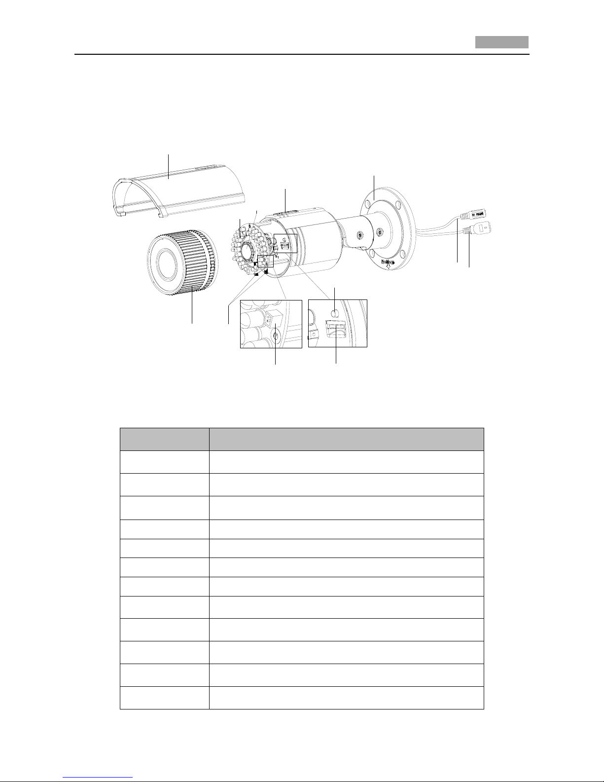
1.1.2 22xx Series Bullet Camera
Camera Overview:
1
2
4
5
6
3
Figure 1-2 Bullet Camera Overview
Table 1-2 Description
No.
Description
1
Lens
2
IR LED
3
Sun Shield
4
Adjusting Screw
5
Network Cable
6
Power Cable
4
www.eyesoniccctv.com
Quick Operation Guide of Network Camera
5
1.1.3 26xx Series Bullet Camera
Camera Overview:
5
4
10
9
7
3
8
6
1
2
12
11
Figure 1-3 Overview
Table 1-3 Overview
No.
Description
1
Sun Shield
2
Front Cover
3
Zoom and Focus Lever
4
IR LED
5
Lens
6
Air Vent
7
Video Output Interface
8
Integrated Bracket
9
Reset Button
10
SD Card Slot
11
Power Cable
12
Network Cable
5
www.eyesoniccctv.com
1.2 Appearance Description of Dome Camera
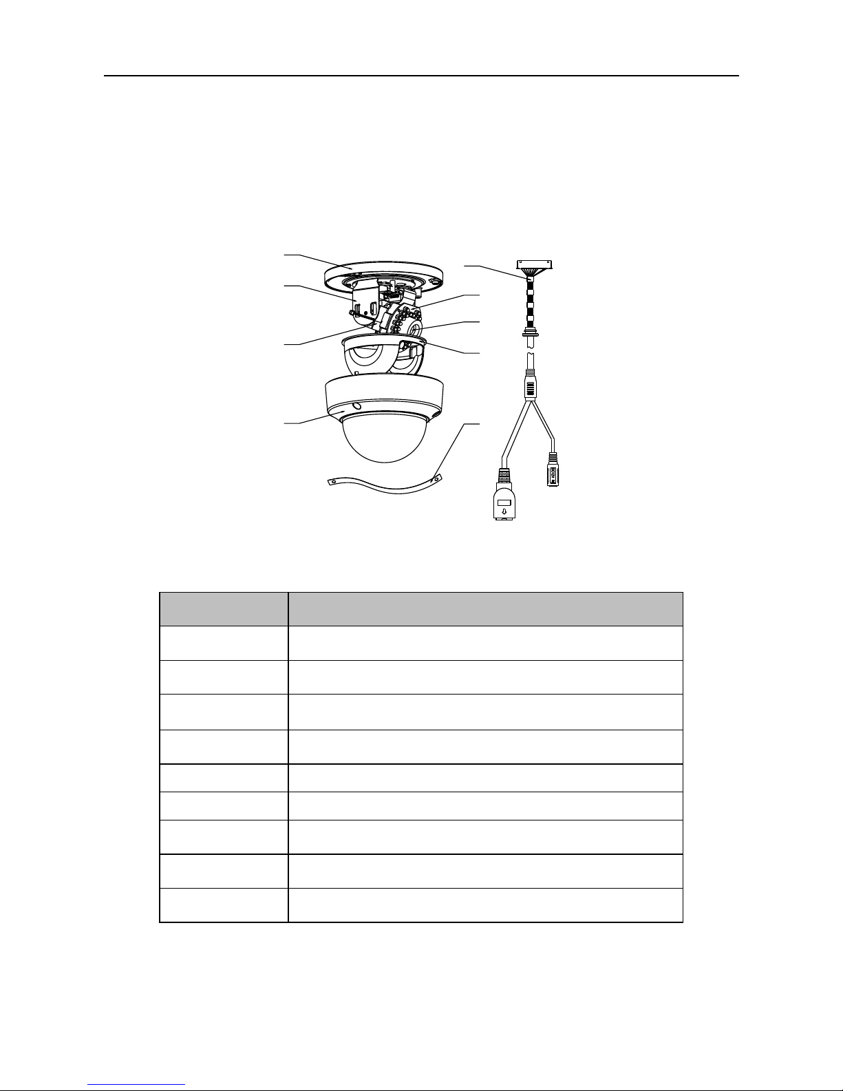
1.2.1 21xx Series Dome Camera
Camera Overview:
1
2
3
4
5
6
7
8
9
Figure 1-4 Overview
Table 1-4 Description
No.
Description
1
Mounting Base
2
Horizontal Stand
3
Vertical Stand
4
Bubble
5
Cables
6
IR LED
7
Lens
8
Black Liner
9
Safety Rope
6
www.eyesoniccctv.com

1.2.2 27xx Series Dome Camera
Camera Description
2
1
3
4
5
6
7
8
9
Figure 1-5 Overview
Table 1-5 Description
No.
Description
1
Bubble
2
Black Liner
3
Reset Button
4
AUX Video Output Interface
5
Serial Port
6
Power Cable
7
Ethernet Cable
8
Adapter Plate
9
Lens
7
www.eyesoniccctv.com
Quick Operation Guide of Network Camera
8
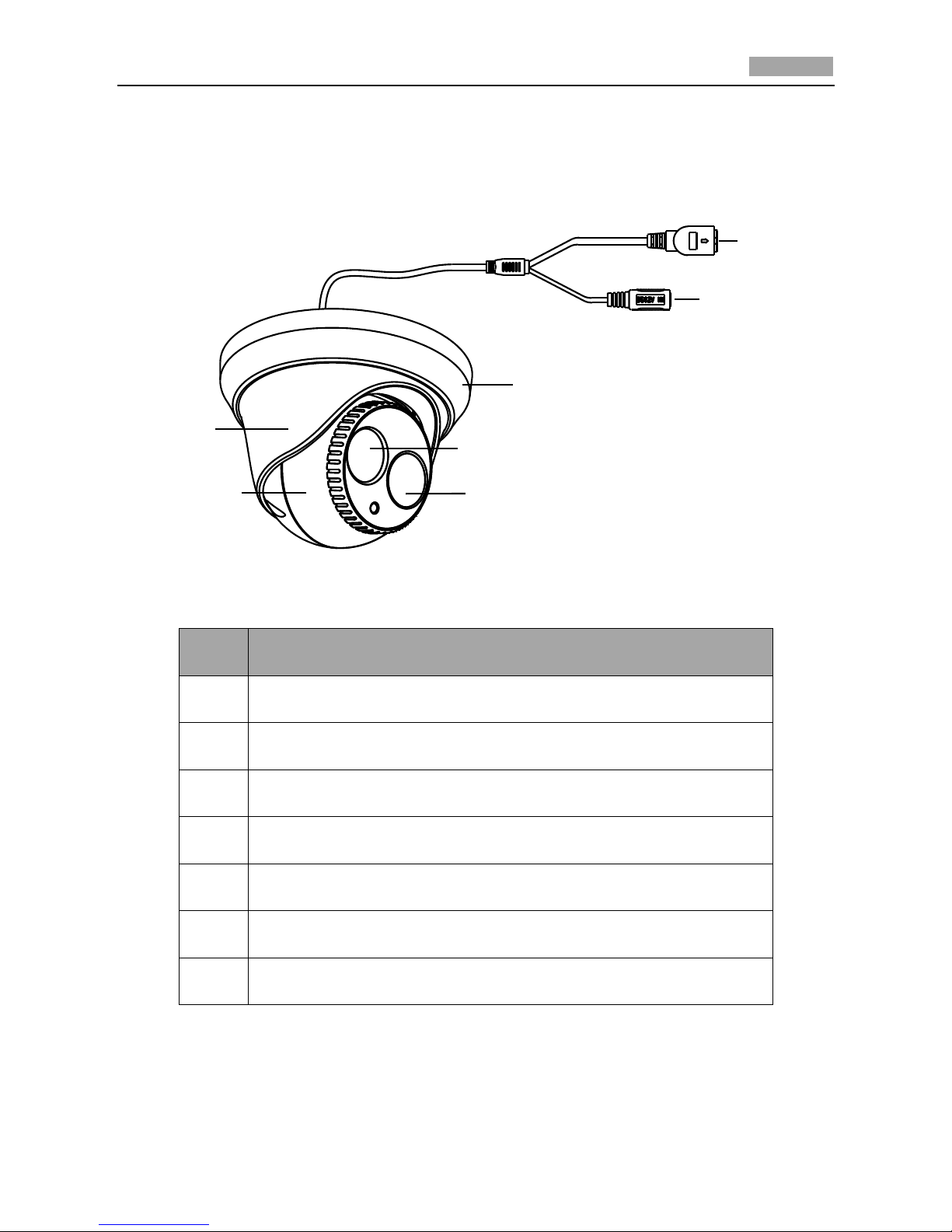
1.3 Appearance Description of Turret Camera
Camera Overview:
3
1
2
4
5
6
7
Figure 1-6 Overview
Table 1-6 Description
NO.
Description
1
10M/100M self-adaptive Ethernet interface
2
Power Cable
3
Trim Ring
4
Lens
5
IR LED
6
Enclosure
7
Camera
8
www.eyesoniccctv.com

Chapter 2 Setting the Network Camera over
the LAN
Purpose:
To view and configure the camera via LAN (Local Area Network), you need to connect the network
camera in the same subnet with your PC. Then install the iVMS-4200 software to search and change
the IP address of the network camera.
The following figure shows the cable connection of a network camera and a PC:
Figure 2-1 Wiring over LAN
Set the IP address of the camera for accessing via LAN.
Steps:
1. Use iVMS-4200 client software to detect the online devices. Please refer to the user manual of
iVMS-4200 client software for detailed information.
● Search online devices automatically
After launch iVMS-4200 software, it automatically searches the online devices every 15
seconds from the subnet where your computer locates. It displays the total number and
information of the searched devices in the Online Devices interface.
Go to Device Management, and click Server tab on the left-top of the window, and you can
see the online devices listed on the right bottom of the window.
Figure 2-2 Search Online Devices
9
www.eyesoniccctv.com
Quick Operation Guide of Network Camera
10
Device can be searched and displayed in the list in 15 seconds after it went online; it will be removed
from the list in 45 seconds after it went offline.
● Search online devices manually
You can also click to refresh the online device list manually. The newly
searched devices will be added to the online list.
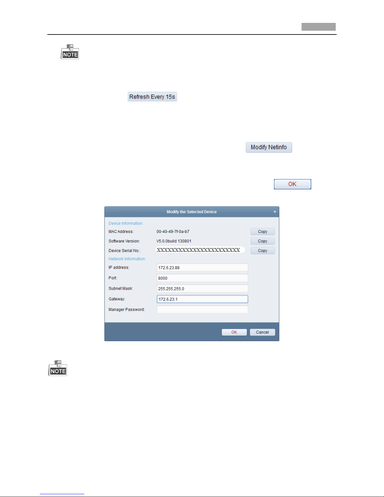
2. Change the IP address and subnet mask to the same subnet as of your PC.
Steps:
1) Click the device to be modified in the device list and click to modify the
network parameters.
2) Edit the modifiable network parameters, e.g. IP address and port number.
3) Enter the admin password in the Manager Password field and click to save
the changes.
Figure 2-3 Modify Network Parameters
The default value of the IP address is “192.0.0.64”. The default user name is “admin”, and
password is “12345”.
For accessing the network camera from different subnets, please set the gateway for the
network camera after you log in.
10
www.eyesoniccctv.com

Chapter 3 Accessing via Web Browsers
System Requirement:
Operating System: Microsoft Windows XP SP1 and above version / Vista / Win7 / Server 2003 /
Server 2008 32bits
CPU: Intel Pentium IV 3.0 GHz or higher
RAM: 1G or higher
Display: 1024×768 resolution or higher
Web Browser: Internet Explorer 6.0 and above version, Apple Safari 5.02 and above version, Mozilla
Firefox 3.5 and above version and Google Chrome8 and above version
Steps:
1. Open the web browser.
2. In the browser address bar, input the IP address of the network camera, e.g., 192.0.0.64 and hit
the enter key to enter the login interface.
3. Input the user name and password.
4. Click .
Figure 3-1 Login Interface
5. Install the plug-in before viewing the live video and managing the camera. Please follow the
installation prompts to install the plug-in.
You may have to close the web browser to finish the installation of the plug-in.
11
www.eyesoniccctv.com

Figure 3-2 Download Plug-in
Figure 3-3 Download New Version Plug-in
Figure 3-4 Install Plug-in
12
www.eyesoniccctv.com

Figure 3-5 Complete the Plug-in Installation
6. Reopen the web browser after the installation of the plug-in and repeat the above steps 2-4 to
login.
For detailed instructions of further configuration, please refer to the user manual of network
camera.
13
www.eyesoniccctv.com

IN NO VAT IV E CUSTOMIZED CC T V SO LUT IO NS
www.eyesoniccctv.com
 Loading...