

Page 1

Blazer Pro All-in-One Server
Quick Start Guide
UD00877B
Page 2

Quick Start Guide of Blazer Pro
User Manual
COPYRIGHT ©2016 Hangzhou Hikvision Digital Technology Co., Ltd.
ALL RIGHTS RESERVED.
Any and all information, including, among others, wordings, pictures, graphs are the properties of Hangzhou
Hikvision Digital Technology Co., Ltd. or its subsidiaries (hereinafter referred to be “Hikvision”). This user
manual (hereinafter referred to be “the Manual”) cannot be reproduced, changed, translated, or distributed,
partially or wholly, by any means, without the prior written permission of Hikvision. Unless otherwise stipulated,
Hikvision does not make any warranties, guarantees or representations, express or implied, regarding to the
Manual.
About this Manual
This Manual is applicable to Blazer Pro All-in-One Server.
The Manual includes instructions for using and managing the product. Pictures, charts, images and all other
information hereinafter are for description and explanation only. The information contained in the Manual is
subject to change, without notice, due to firmware updates or other reasons. Please find the latest version in the
company website (http://overseas.hikvision.com/en/).
Please use this user manual under the guidance of professionals.
Trademarks Acknowledgement
and other Hikvision’s trademarks and logos are the properties of Hikvision in various
jurisdictions. Other trademarks and logos mentioned below are the properties of their respective owners.
Legal Disclaimer
TO THE MAXIMUM EXTENT PERMITTED BY APPLICABLE LAW, THE PRODUCT DESCRIBED, WITH
ITS HARDWARE, SOFTWARE AND FIRMWARE, IS PROVIDED “AS IS”, WITH ALL FAULTS AND
ERRORS, AND HIKVISION MAKES NO WARRANTIES, EXPRESS OR IMPLIED, INCLUDING WITHOUT
LIMITATION, MERCHANTABILITY, SATISFACTORY QUALITY, FITNESS FOR A PARTICULAR
PURPOSE, AND NON-INFRINGEMENT OF THIRD PARTY. IN NO EVENT WILL HIKVISION, ITS
DIRECTORS, OFFICERS, EMPLOYEES, OR AGENTS BE LIABLE TO YOU FOR ANY SPECIAL,
CONSEQUENTIAL, INCIDENTAL, OR INDIRECT DAMAGES, INCLUDING, AMONG OTHERS,
DAMAGES FOR LOSS OF BUSINESS PROFITS, BUSINESS INTERRUPTION, OR LOSS OF DATA OR
1
Page 3

Quick Start Guide of Blazer Pro
DOCUMENTATION, IN CONNECTION WITH THE USE OF THIS PRODUCT, EVEN IF HIKVISION HAS
BEEN ADVISED OF THE POSSIBILITY OF SUCH DAMAGES.
REGARDING TO THE PRODUCT WITH INTERNET ACCESS, THE USE OF PRODUCT SHALL BE
WHOLLY AT YOUR OWN RISKS. HIKVISION SHALL NOT TAKE ANY RESPONSIBILITES FOR
ABNORMAL OPERATION, PRIVACY LEAKAGE OR OTHER DAMAGES RESULTING FROM CYBER
ATTACK, HACKER ATTACK, VIRUS INSPECTION, OR OTHER INTERNET SECURITY RISKS;
HOWEVER, HIKVISION WILL PROVIDE TIMELY TECHNICAL SUPPORT IF REQUIRED.
SURVEILLANCE LAWS VARY BY JURISDICTION. PLEASE CHECK ALL RELEVANT LAWS IN YOUR
JURISDICTION BEFORE USING THIS PRODUCT IN ORDER TO ENSURE THAT YOUR USE CONFORMS
THE APPLICABLE LAW. HIKVISION SHALL NOT BE LIABLE IN THE EVENT THAT THIS PRODUCT IS
USED WITH ILLEGITIMATE PURPOSES.
IN THE EVENT OF ANY CONFLICTS BETWEEN THIS MANUAL AND THE APPLICABLE LAW, THE
LATER PREVAILS.
2
Page 4

Quick Start Guide of Blazer Pro
Regulatory Information
FCC Information
FCC compliance: This equipment has been tested and found to comply with the limits for a Class A digital device,
pursuant to part 15 of the FCC Rules. These limits are designed to provide reasonable protection against harmful
interference when the equipment is operated in a commercial environment. This equipment generates, uses, and
can radiate radio frequency energy and, if not installed and used in accordance with the instruction manual, may
cause harmful interference to radio communications. Operation of this equipment in a residential area is likely to
cause harmful interference in which case the user will be required to correct the interference at his own expense.
FCC Conditions
This device complies with part 15 of the FCC Rules. Operation is subject to the following two conditions:
1. This device may not cause harmful interference.
2. This device must accept any interference received, including interference that may cause undesired operation.
EU Conformity Statement
This product and - if applicable - the supplied accessories too are marked with "CE" and comply
therefore with the applicable harmonized European standards listed under the EMC Directive
2004/108/EC, the RoHS Directive 2011/65/EU.
2012/19/EU (WEEE directive): Products marked with this symbol cannot be disposed of as unsorted
municipal waste in the European Union. For proper recycling, return this product to your local
supplier upon the purchase of equivalent new equipment, or dispose of it at designated collection
points. For more information see: www.recyclethis.info
2006/66/EC (battery directive): This product contains a battery that cannot be disposed of as unsorted
municipal waste in the European Union. See the product documentation for specific battery
information. The battery is marked with this symbol, which may include lettering to indicate
cadmium (Cd), lead (Pb), or mercury (Hg). For proper recycling, return the battery to your supplier or to a
designated collection point. For more information see: www.recyclethis.info
Industry Canada ICES-003 Compliance
This device meets the CAN ICES-3 (A)/NMB-3(A) standards requirements.
3
Page 5
Quick Start Guide of Blazer Pro
Warnings Follow these
safeguards to prevent serious
injury or death.
Cautions Follow these
precautions to prevent
potential injury or material
damage.
Safety Instruction
These instructions are intended to ensure that user can use the product correctly to avoid danger or property loss.
The precaution measure is divided into “Warnings” and “Cautions”
Warnings: Serious injury or death may occur if any of the warnings are neglected.
Cautions: Injury or equipment damage may occur if any of the cautions are neglected.
Warnings
● Proper configuration of all passwords and other security settings is the responsibility of the installer and/or
end-user.
● In the use of the product, you must be in strict compliance with the electrical safety regulations of the nation
and region. Please refer to technical specifications for detailed information.
● Input voltage should meet both the SELV (Safety Extra Low Voltage) and the Limited Power Source with
100~240 VAC, 48 VDC or 12 VDC according to the IEC60950-1 standard. Please refer to technical
specifications for detailed information.
● Do not connect several devices to one power adapter as adapter overload may cause over-heating or a fire
hazard.
● Please make sure that the plug is firmly connected to the power socket.
● If smoke, odor or noise rise from the device, turn off the power at once and unplug the power cable, and then
please contact the service center.
Preventive and Cautionary Tips
Before connecting and operating your device, please be advised of the following tips:
• Ensure unit is installed in a well-ventilated, dust-free environment.
• Unit is designed for indoor use only.
• Keep all liquids away from the device.
• Ensure environmental conditions meet factory specifications.
• Ensure unit is properly secured to a rack or shelf. Major shocks or jolts to the unit as a result of dropping it
may cause damage to the sensitive electronics within the unit.
• Use the device in conjunction with an UPS if possible.
• Power down the unit before connecting and disconnecting accessories and peripherals.
• A factory recommended HDD should be used for this device.
• Improper use or replacement of the battery may result in hazard of explosion. Replace with the same or
equivalent type only. Dispose of used batteries according to the instructions provided by the battery
manufacturer.
4
Page 6

Quick Start Guide of Blazer Pro
Symbol
Description
Indicates a potentially hazardous situation, which if not avoided,
could result in equipment damage, data loss, performance
degradation, or unexpected results.
Symbol Conventions
The symbols that may be found in this document are defined as follows.
5
Page 7

Quick Start Guide of Blazer Pro
TABLE OF CONTENTS
Overview ......................................................................................................................................................... 7
Blazer Pro Pre-Installation .............................................................................................................................. 7
Blazer Pro Installation ..................................................................................................................................... 7
Front Panel ....................................................................................................................................................... 8
Rear Panel ........................................................................................................................................................ 9
Specifications .................................................................................................................................................. 10
HDD Storage Calculation Chart ................................................................................................................... 11
Basic Hardware Connection and Startup .................................................................................................... 12
Network Connection ................................................................................................................................ 12
Output Connection ................................................................................................................................... 12
Hard Disk Installation ................................................................ .............................................................. 12
Peripheral Connections ............................................................................................................................ 14
Wiring of Alarm Input ...................................................................................................................... 14
Wiring of Alarm Output ................................................................................................................... 14
Using of Alarm Connectors .............................................................................................................. 14
Controller Connection ...................................................................................................................... 15
Power Connection and Startup ................................................................................................................. 15
Network Parameters Settings ........................................................................................................................ 15
For Video Management System ............................................................................................................... 15
For Blazer Pro Storage Device ................................................................................................................. 17
Accessing Blazer Pro via Web Manager ....................................................................................................... 18
Quick Start ..................................................................................................................................................... 20
IP Address Settings .................................................................................................................................. 20
Resource Management and Live View ..................................................................................................... 21
Adding the Network Camera ............................................................................................................ 21
Area Management ............................................................................................................................ 22
Live View ......................................................................................................................................... 23
Recording Schedule Settings and Playback ............................................................................................. 24
Recording Schedule Settings ............................................................................................................ 24
Remote Playback .............................................................................................................................. 26
Searching Video Files for Playback ................................................................................................. 26
Playing Video Files .......................................................................................................................... 26
Event Configuration ................................................................................................................................. 27
Configuring Motion Detection Alarm .............................................................................................. 27
Checking Alarm Information ........................................................................................................... 28
Shutting Down the Blazer Pro ....................................................................................................................... 29
6
Page 8

Quick Start Guide of Blazer Pro
Overview
The Blazer Pro is an all-in-one server that combines Hikvision’s powerful video management system (VMS) with
a video storage device. The Blazer Pro can manage up to 256 network cameras for recording, live view, and
playback. With the power of VMS, sophisticated alarm management is possible, as well as the VMS add-ons, such
as license plate recognition, POS integration, business intelligence, and GIS map. The Blazer Pro’s unique design
provides both powerful storage and advanced centralized video management capabilities.
Blazer Pro Pre-Installation
The Blazer Pro is highly advanced surveillance equipment that should be installed with care. Please take into
consideration the following precautionary steps before installation of the Blazer Pro.
1. Keep all liquids away from the Blazer Pro.
2. Install the Blazer Pro in a well-ventilated and dust-free area.
3. Ensure environmental conditions meet factory specifications.
4. Install a manufacturer recommended HDD.
Blazer Pro Installation
During the installation of the Blazer Pro:
1. Use brackets for rack mounting.
2. Ensure there is ample room for audio and video cables.
3. When routing cables, ensure that the bend radius of the cables are no less than five times than its diameter.
4. Connect both the alarm and RS-485 cable.
5. Allow at least 2cm (≈0.75-inch) of space between racks mounted devices.
6. Ensure the Blazer Pro is grounded.
7. Environmental temperature should be within the range of 0º C to +40º C, 32º F to 104º F.
8. Environmental humidity should be within the range of 10% ~ 90%.
7
Page 9

Quick Start Guide of Blazer Pro
No.
Name
Function Description
1
Front Panel Lock
You can lock or unlock the panel by the key.
2
Master Board
Indicator
Hardware
Normally blue when the master board works properly.
System
Normally blue when the CMS (Central Management Server) of
the video management system running properly.
3
Secondary Board
Indicator
Hardware
Normally blue when the secondary board works properly.
System
Indicate the HDD status. Blinks red when data is being read
from or written to HDD.
4
POWER ON / OFF
Power on/off switch.
5
USB Interfaces (for Master Board)
Universal Serial Bus (USB) ports for additional devices such as
USB mouse and USB Hard Disk Drive (HDD).
Front Panel
8
Page 10
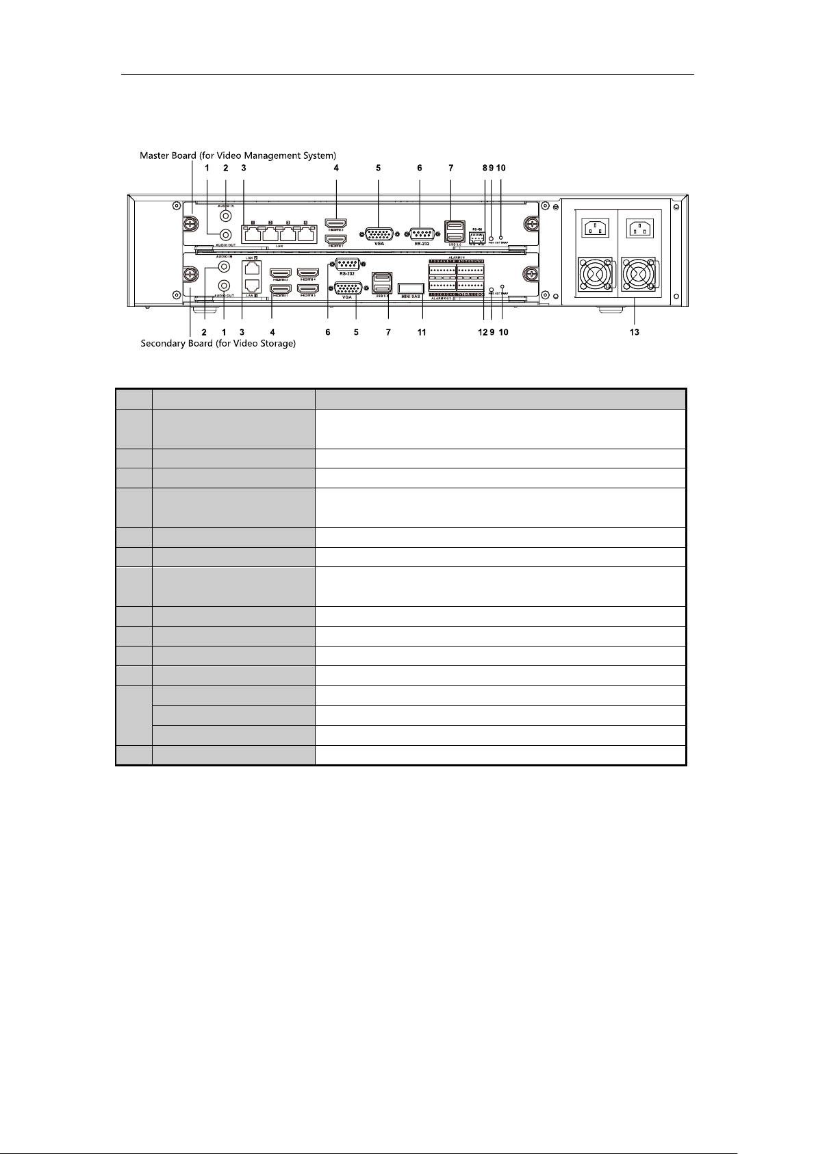
Quick Start Guide of Blazer Pro
No.
Item
Description
1
AUDIO OUT
RCA connector for audio output. This connector is synchronized with
VGA video output.
2
AUDIO IN
RCA connector for audio input.
3
LAN Interface
LAN network interfaces.
4
HDMITM
HDMITM video output connector. The HDMI
TM
interfaces can also be
used for video wall display.
5
VGA
Connector for VGA output. Display local video output and menu.
6
RS-232 Interface
Connector for RS-232 devices.
7
USB 3.0 interface
Universal Serial Bus (USB) ports for additional devices such as USB
mouse and USB Hard Disk Drive (HDD).
8
RS-485 Interface
Connector for RS-485 devices.
9
Power Indicator
Turns green when the corresponding board is powered up.
10
Hot Swap Button
Button for powering off the corresponding board.
11
miniSAS
Connects to SAS expansion enclosure.
12
ALARM IN
Connector for alarm input.
ALARM OUT
Connector for alarm output.
RS-485 Interface
Connector for RS-485 devices.
13
AC 100V ~ 240V
AC 100V ~ 240V power supply.
Rear Panel
9
Page 11

Quick Start Guide of Blazer Pro
Model Blazer Pro (256-channel)
Blazer Pro (128-channel)
Video
Management
System
Number of Connected Cameras per System
Maximum 256
Maximum 128
Number of Connected Devices or Mobile Video
Recorders (Sold Separately) per System
Maximum 256
Maximum 128
Number of Connected Mobile Terminals (Sold
Separately)
Maximum 64
Maximum 64
Number of Connected Alarm Inputs per System
Maximum 1024
Maximum 1024
Number of Connected Alarm Outputs per System
Maximum 1024
Maximum 1024
Control Clients per System
Maximum 16
Maximum 16
Web Clients per System
Maximum 16
Maximum 16
Mobile Clients per System
Maximum 64
Maximum 64
Web Managers per System
Unlimited
Unlimited
Number of Users
Unlimited
Unlimited
Number of Roles
Maximum 64
Maximum 64
PTZ Control Permission Levels
Maximum 100
Maximum 100
Number of Stream Media Servers Per System
Maximum 16
Maximum 16
POS Systems Access (Sold Separately)
Maximum 100
Maximum 100
Video Input Bandwidth per SMS
Maximum 200 × 2 Mbps
Maximum 200 × 2 Mbps
Video Output Bandwidth per SMS
Maximum 200 × 2 Mbps
Maximum 200 × 2 Mbps
SATA
1 SATA interface for 1 HDD (for
data storage )
1 SATA interface for 1 HDD (for data
storage )
Video
Storage
Device
Incoming Bandwidth
640 Mbps
or 320 Mbps (when RAID is
enabled)
400 Mbps
or 320 Mbps (when RAID is enabled)
Outgoing Bandwidth
640 Mbps
or 320 Mbps (when RAID is
enabled)
400 Mbps
or 320 Mbps (when RAID is enabled)
Live View / Playback Resolution
6 MP/5 MP/3 MP
/1080p/UXGA/720p/VGA/4CIF/
DCIF/2CIF/CIF/QCIF
6 MP/5 MP/3 MP
/1080p/UXGA/720p/VGA/4CIF/DCI
F/2CIF/CIF/QCIF
Recording Channels
256 channels
128 channels
SATA
7 SATA interfaces for 7 HDDs
(for the video storage)
7 SATA interfaces for 7 HDDs (for
the video storage)
miniSAS
1 miniSAS interface
1 miniSAS interface
Capacity
Up to 6 TB capacity for each
HDD
Up to 6 TB capacity for each HDD
Array Type
RAID 0, RAID 1, RAID 5, RAID
10
RAID 0, RAID 1, RAID 5, RAID 10
Power Supply
100 to 240 VAC, 6.3 A, 50 to 60
Hz
100 to 240 VAC, 6.3 A, 50 to 60 Hz
Consumption (without Hard Disk)
≤250 W
≤250 W
Working Temperature
0º C to +40º C (32º F to 104º F)
0º C to +40º C (32º F to 104º F)
Working Humidity
10% to 90%
10% to 90%
Chassis
19-inch rack-mounted 2U chassis
19-inch rack-mounted 2U chassis
Dimensions (W × D × H)
442 mm × 550 mm × 93 mm
(17.4" × 21.7" × 3.7")
442 mm × 550 mm × 93 mm (17.4" ×
21.7" × 3.7")
Weight (without Hard Disk)
≤13.6 kg (29.98 lb)
≤13.6 kg (29.98 lb)
Specifications
10
Page 12

Quick Start Guide of Blazer Pro
Bit Rate
Storage Used
96 K
42 MB
128K
56 MB
160K
70 MB
192K
84 MB
224K
98 MB
256K
112 MB
320K
140 MB
384K
168 MB
448K
196 MB
512K
225 MB
640K
281 MB
768K
337 MB
896K
393 MB
1024K
450 MB
1280K
562 MB
1536K
675 MB
1792K
787 MB
2048K
900 MB
4096K
1800 MB
8192K
3600 MB
16384K
7.2 GB
HDD Storage Calculation Chart
The following chart shows an estimation of storage space used based on recording at one camera for an hour at a
fixed bit rate.
Note:
Please note that supplied values for storage space used is just for reference. The storage values in the chart are
estimated by formulas and may have some deviation from actual value.
11
Page 13

Quick Start Guide of Blazer Pro
Basic Hardware Connection and Startup
Before you can access the system via network, you need to properly power on the server and connect it to network.
Network Connection
Note: Consult your network administrator before installing the server to avoid possible network conflicts.
Use the network port on the rear panel and a network cable with RJ-45 connectors to connect the server to your
system network.
The LAN interfaces of the master board (up) are used for connecting the video management system to the network,
and the LAN interfaces of the secondary board (down) are used for connecting the Blazer Pro Storage Device to
the network.
For the LAN interface of the secondary board (down), the default IP address of LAN 1 is 192.0.0.64 and the
default IP address of LAN 2 is 192.1.0.64.
Output Connection
Connect a VGA cable or HDMI cable to the video out interface (VGA or HDMI) on the server.
Connect the VGA cable or HDMI1 cable to the display unit.
If you need to locally operate the video management system and Blazer Pro Storage Device, please connect the
display units to the master board and secondary board respectively.
Hard Disk Installation
Before you start:
Disconnect the power from the Blazer Pro before installing a hard disk drive (HDD). A factory recommended
HDD should be used for this installation.
Up to 8 SATA hard disks can be installed on your Blazer Pro.
Note: 7 HDDs are used for Blazer Pro Storage Device of secondary board and 1 HDD (upper right corner) is used
for data storage of master board.
Tools Required: Screwdriver.
Steps:
1. Fasten the hard disk mounting handle to the hard disk with screws.
2. Insert the key and turn in clockwise direction to open the panel lock.
12
Page 14

Quick Start Guide of Blazer Pro
3. Press the buttons on the panel of two sides and open the front panel.
4. Insert the hard disk along the slot until it is placed into position.
5. Repeat the above steps to install other hard disks onto the Blazer Pro. After having finished the installation
of all hard disks, close the front panel and lock it with the key again.
13
Page 15

Quick Start Guide of Blazer Pro
Peripheral Connections
Wiring of Alarm Input
The alarm input is an open/closed relay. To connect the alarm input to the device, use the following diagram.
Notes:
If the alarm input is not an open/close relay, please connect an external relay between the alarm input and the
device.
The following figures only for reference, subject to the actual device.
Wiring of Alarm Output
To connect to an alarm output (AC or DC load), use the following diagram:
DC Load Connection Diagram AC Load Connection Diagram
For DC load, the jumpers can be used within the limit of 12V/1A safely.
To connect an AC load, jumpers should be left open (you must remove the jumper on the motherboard in the
Blazer Pro). Use an external relay for safety (as shown in the figure above).
There are 4 jumpers (JP1, JP2, JP3, and JP4) on the motherboard, each corresponding with one alarm output. By
default, jumpers are connected. To connect an AC load, jumpers should be removed.
Example:
If you connect an AC load to the alarm output 3 of the Blazer Pro, then you must remove the JP3.
Using of Alarm Connectors
To connect alarm devices to the Blazer Pro:
1. Disconnect pluggable block from the ALARM IN /ALARM OUT terminal block.
14
Page 16

Quick Start Guide of Blazer Pro
2. Unfasten stop screws from the pluggable block, insert signal cables into slots and fasten stop screws. Ensure
signal cables are in tight.
3. Connect pluggable block back into terminal block.
Controller Connection
To connect a controller to the Blazer Pro:
1. Disconnect pluggable block from the RS-485 terminal block of secondary board.
2. Unfasten stop screws from the D+, D- pluggable block, insert signal cables into slots and fasten stop screws.
Ensure signal cables are in tight.
3. Connect Ta on controller to D+ on terminal block and Tb on controller to D- on terminal block. Fasten stop
screws.
4. Connect pluggable block back into terminal block.
Note: Make sure both the controller and Blazer Pro are grounded.
Power Connection and Startup
Plug the power supply (refer to the Specifications) into an electrical outlet. It is HIGHLY recommended that an
Uninterruptible Power Supply (UPS) be used in conjunction with the device.
The Power indicator LED on the rear panel should turn green indicating that the unit begins to start up.
After startup, the Power indicator LED remains green.
The server contains two sub-systems: Blazer Pro Storage Device and video management system.
For the first-time access to the video management system, you need to connect a display unit to master board via
VGA or HDMI interface. In this manual, we only introduce the basic settings for video management system. For
detailed configuration about video management system, please refer to the User Manual of Blazer Pro Web
Manager.
For operating the Blazer Pro Storage Device locally, you need to connect a display unit to secondary board via
VGA or HDMI interface. For detailed configuration about Blazer Pro Storage Device, please refer to the User
Manual of Blazer Pro Storage Device.
Network Parameters Settings
You need to properly set the network parameters before you can access to the server via network.
For Video Management System
Before you start:
The video management system (master board) should be properly connected to the network and the video output
should be connected to a display unit.
You also have to connect a USB mouse and USB keyboard via the available USB interface before you can
properly configure the system.
Steps:
1. Login in the video management system. The default password of the admin user of the operating system is
12345.
You must change this default password to better protect against security risks, such as the unauthorized
access by others to the product that may prevent the product from functioning properly and/or lead to
15
Page 17

Quick Start Guide of Blazer Pro
other undesirable consequences. For changing the password, please refer to the help file of the operating
system for detailed configuration.
For your privacy, we strongly recommend changing the password to something of your own choosing
(using a minimum of 8 characters, including upper case letters, lower case letters, numbers, and special
characters) in order to increase the security of your product.
Proper configuration of all passwords and other security settings is the responsibility of the installer
and/or end-user.
2. Enter the Control Panel of the operating system. For how to access the control panel, refer to the help file of
the operating system.
If using Category view, find the Programs category, and click View network status and tasks.
If using Small icons or Large icons view, select Network and Sharing Center.
3. Click the Ethernet with internet connection and click Properties in the pop-up window.
4. In the This connection uses the following items: field, double-click Internet Protocol Version 4
(TCP/IPv4).
5. In the pop-up window, set the network parameters.
Obtain an IP address (DNS server address) automatically: You can get IP settings assigned automatically
if your network supports this capability.
Use the following IP address (DNS server address): Please ask your network administrator for the
16
Page 18

Quick Start Guide of Blazer Pro
appropriate IP settings.
6. Click OK to save the settings.
For Blazer Pro Storage Device
Before you start:
The Blazer Pro Storage Device (secondary board) should be properly connected to the network and the video
output should be connected to a display unit.
Steps:
1. Enter the Network Settings interface. For details, refer to the User Manual of Blazer Pro Storage Device.
Menu >Configuration>Network
The default password of the admin user of the Blazer Pro Storage Device is Blazer_12345.
You must change this default password to better protect against security risks, such as the unauthorized
access by others to the product that may prevent the product from functioning properly and/or lead to
other undesirable consequences. For changing the password, please refer to the User Manual of Blazer
Pro Storage Device.
For your privacy, we strongly recommend changing the password to something of your own choosing
(using a minimum of 8 characters, including upper case letters, lower case letters, numbers, and special
characters) in order to increase the security of your product.
Proper configuration of all passwords and other security settings is the responsibility of the installer
and/or end-user.
2. Select the General tab.
17
Page 19

Quick Start Guide of Blazer Pro
3. In the General Settings interface, you can configure the following settings: Working Mode, NIC Type, IPv4
Address, IPv4 Gateway, MTU and DNS Server.
Working Mode
There are two 10M/100M/1000M NIC cards provided, and it allows the device to work in the Multi-address,
Load Balance and Net-fault Tolerance modes.
Multi-address Mode: The parameters of the two NIC cards can be configured independently. You can
select LAN1, LAN2 in the NIC type field for parameter settings.
Load Balance Mode: You can select one NIC card as default route. And then the system is connecting
with the extranet the data will be forwarded through the default route.
Net-fault Tolerance Mode: The two NIC cards use the same IP address, and you can select the Main
NIC to LAN1, LAN2. By this way, in case of one NIC card failure, the device will automatically enable
another standby NIC card so as to ensure the normal running of the whole system.
If the DHCP server is available, you can click the checkbox of DHCP to automatically obtain an IP address
and other network settings from that server.
Note: The valid value range of MTU is 500 ~ 9676.
4. After having configured the general settings, click Apply button to save the settings.
Accessing Blazer Pro via Web Manager
You can access the Blazer Pro via Web Manager which is a B/S client for management of Blazer Pro.
Notes:
If you have properly set the network parameters for the master board, you can access the video management
system via network. You can also access the system it locally. Here we only introduce the access to the
system locally. For more details, refer to the User Manual of Blazer Pro Web Manager.
For accessing the video management system via network, you should turn video management system’s
firewall off.
Firewall will not help prevent hackers or malicious software from gaining access to your product through
the network after you turn firewall off.
If you cannot access the video management system via network, you can turn your PC’s firewall off and try
again.
18
Page 20

Quick Start Guide of Blazer Pro
Steps:
1. In the address bar of the web browser, input the address of the CMS (Central Management Server) and
press the Enter key. A login window will pop up. For locally accessing the system, you can also
double-click on the desktop to pop up the login window.
Note: The address is in the format of http://IP address of CMS. If you access the system locally, the IP
address is 127.0.0.1 or localhost.
Example: If the IP address of CMS is 172.6.21.96, and you should enter http://172.6.21.96 in the
address bar.
2. In the pop-up window, input the customized password in the New Password and Confirm Password field,
and click OK to set the password.
The password strength can be checked by the system. For your privacy, you must set the password
to something of your own choosing (using a minimum of 8 characters, including upper case letters,
lower case letters, numbers, and special characters) in order to increase the security of your
product.
Proper configuration of all passwords and other security settings is the responsibility of the
installer and/or end-user.
3. For the first time to login, you should install the plug-in before you can access the functions.
I. Click Download Plug-in, save the plug-in file and then close the web browser.
II. Install the plug-in according to the prompt.
III. After the installation, re-open the web browser and log into the Blazer Pro (step 1).
4. Choose user type in the drop-down list.
CMS User: The user of current CMS.
RSM User: The user of RSM that has the permission for accessing the current CMS.
Note: If you want to select RSM User, you have to configure the RSM. For configuring RSM, please
contact our technical support engineers.
5. Input the new password, (optional) check the checkbox of Remember Password to save the password
and click Login.
Notes:
If failed login attempt is detected, you are required to input the verification code before you can login
successfully.
The account will be frozen for 10 minutes after 5 failed login attempts.
19
Page 21

Quick Start Guide of Blazer Pro
If you have updated your Blazer Pro, you may need to clear the cache of your web browser to display
the Web Manager page properly. Consult your IT system administrator if you do not know how to
clear the cache.
Quick Start
Here we introduce the configuration for some basic functions of the Blazer Pro via Web Manager and Control
Client.
IP Address Settings
Purpose:
In order to make the service modules function properly, you must edit the Blazer Pro IP address before performing
other operations.
Steps:
1. Log into the Blazer Pro via Web Manager, click the System Configuration tab and click IP Address.
2. Input the Video Management System IP address that you set in Section Network Parameters Settings in LAN
IP Address field.
3. Click Save to confirm the settings.
4. Open the Service Manager dialog (Start menu>Service Manager, or Notification Area>Service Manager) and
20
Page 22

Quick Start Guide of Blazer Pro
click Setting.
5. Input the Video Management System IP address that you set in Section Network Parameters Settings in CMS
IP field.
6. Click OK to save the settings.
Resource Management and Live View
Purpose:
Before you can live view, playback via the Control Client or set recording schedule, event configuration via Web
Manager, you need to add network cameras to the system and manage them by areas.
Log into the Blazer Pro via Web Manager, and click Physical View tab to open the device and server management
page.
By default, the Blazer Pro Storage Device is added to the system. Here we introduce the configuration of adding
network cameras via the Blazer Pro Storage Device. For other methods to add the device, refer to the User Manual
of Blazer Pro Web Manager.
Adding the Network Camera
Before you start:
You must properly configure the network settings for the Blazer Pro Storage Device.
Steps:
1. Click Configuration of the Blazer_storage board in the Operation column to pop up the remote
configuration interface.
2. Click Camera under System to enter the network camera management interface.
21
Page 23

Quick Start Guide of Blazer Pro
3. Click Add and edit the parameters in the pop-up window to add the network cameras.
Registration Mode: Select to add the camera via IP address or domain name.
IP/Domain: Input the IP address or domain name of the camera.
Port: Input the device port No.. The default value is 8000.
User Name: Input the user name of the device.
Password: Input the password of the device.
Protocol Type: Select the protocol that the camera adopts.
4. Click Next and check the checkbox(es) to select the camera(s) to add.
5. Click Save to confirm the settings.
6. Click Apply and then click Refresh to get the latest status.
7. Click to exit the remote configuration interface.
8. Click Blazer_storage board in the Alias column, and click Back to get the latest status.
Area Management
Steps:
1. Click the Logical View tab and click to open the Add Area dialog box.
2. Select the parent area in the Superior drop-down list.
22
Page 24

Quick Start Guide of Blazer Pro
3. Input an area name as you want. Optionally, you can select a stream media server for the area to get the
video stream of the cameras belonging to this area via the server.
4. Click Save to add the new area.
5. In the area tree panel, click to select an element of the area. The element refers to the encoding channel,
alarm input, alarm output, and POS that belonging to the area.
6. Click Add and a dialog box pops up.
For adding the camera / alarm input / alarm output:
I. Check the checkbox(es) to select the elements to be added.
II. (Optional) Check Synchronize Camera Name checkbox to get the camera name from the device.
III. (Optional) Check Get Device Recording Schedule checkbox to obtain the recording schedule configured on
the local device and the recording task will automatically perform according to schedule.
IV. Click OK to save the settings.
For adding the POS:
I. Input the required parameters.
Name: Input a name as you want.
IP Address: Input the IP address of the POS terminal.
Linked Camera: Select a camera of the area to link with the POS terminal.
Protocol Type: Select the protocol for connecting to the POS terminal.
II. Click OK to save the settings.
Notes:
Up to 64 cameras can be added to one area.
A camera, alarm input, alarm output, or POS can only be added to one area. You can input the key word in the
text filed and click Search to find the required device, camera, alarm input, alarm output, or POS.
The add-ons are available if you purchase the corresponding License. Please contact our sales for detailed
information.
Live View
After adding the encoding devices and managing the area, you can live view the camera via Control Client which
is a C/S software providing multiple operating functionalities.
Login via Control Client
Two kinds of user (normal user and domain user) are supported for accessing the Blazer Pro via Control Client.
Here we only introduce the normal user login, please refer to the User Manual of Blazer Pro Control Client for the
domain user login.
Steps:
1. Double-click on the desktop to run the Control Client.
2. Select Normal Login on the bottom.
3. Click Show Server Address and input the parameters.
IP Address: Input the address (IP address or domain name) of the CMS that you want to connect to.
Port: Input the port No. of the CMS. By default, it's 80.
4. Input the normal user name and password of the Blazer Pro.
5. (Optional) Check the checkbox Remember Password to keep the password.
6. (Optional) Check the checkbox Enable Auto-login to log into the software automatically.
7. Click Login to enter the Control Client.
Notes:
23
Page 25

Quick Start Guide of Blazer Pro
If failed login attempt is detected, you are required to input the verification code before you can login
successfully.
The account will be frozen for 10 minutes after 5 failed password attempts.
Live View
Steps:
1. Open the Main View page.
2. Optionally, click and select the window division mode for live view.
3. Click-and-drag the camera to the display window, or double-click the camera name after selecting the
display window to start the live view.
Note: For detailed operations about live view, please refer to the User Manual of Blazer Pro Control Client.
Recording Schedule Settings and Playback
Before you can view the record files of the camera via the Control Client, you need to set the recording schedule
via Web Manager.
Recording Schedule Settings
Purpose:
Blazer Pro provides two storage methods (storing on the local device and storing on the Central Storage Server
(Storage Server or Central Video Recorder)) for storing the video files of the cameras according to the configured
recording schedule.
Notes:
Here we only introduce the method of storing video files on the local device. The following steps are also
applicable for storing the video files on the Blazer Pro Storage Device.
The Storage Server refers to the PC that installs the Storage Server module. For details, please refer to User
Manual of Blazer Pro Web Manager.
Before you start:
The local devices, including the DVRs, NVRs, and Network Cameras, should provide storage devices such as the
HDDs, Net HDDs and SD/SDHC cards for video files. The newly installed storage devices need to be formatted.
Go to the remote configuration page ( Physical View > Configuration) of the device, click Storage > General,
select the HDD, Net HDD or SD/SDHC card, and click Format to initialize the selected storage device.
Steps:
1. Log into the Blazer Pro via Web Manager, and click the Record Schedule tab to open the Record
Schedule page.
2. Select an area and click Add to pop up the Record Settings dialog.
Note: If no camera has been configured with recording schedule, click Set Record Schedule to activate
the Record Settings dialog.
24
Page 26

Quick Start Guide of Blazer Pro
3. Click to select the camera for configuring the recording settings.
4. Click Next to set the recording schedule and storage location. By default, the Storage 1 is enabled.
5. You can check Get Device Recording Schedule checkbox to obtain the recording schedule configured
on the local device. Or you can perform the following steps to set the recording schedule as required.
6. Select the record schedule template for Storage 1.
All-day Template: All-day continuous recording whole week.
Weekday Template: All-day continuous recording from Monday to Friday.
Weekend Template: All-day continuous recording from Saturday to Sunday.
Template 01-08: You can edit the templates as desired. Click Configuration to enter the Record
Schedule Template interface. For detailed configuration, please refer to User Manual of Blazer Pro
Web Manager.
7. Select the stream type for recording.
8. Select to store the record files on the local device (Encoding Device).
Note: For the cameras connected to the Blazer Pro Storage Device, select Encoding Device for storing
the record files on the secondary board.
9. Click OK to save the settings.
After configuring the recording settings for the camera, the recording schedule item will display under the area.
25
Page 27

Quick Start Guide of Blazer Pro
Remote Playback
Purpose:
After configuring the recording settings for the camera via the Web Manager, the video files stored on the local
device can be searched and played back remotely via Control Client.
Note: Here we only introduce the playback of continuous video files. For other operations about playback, please
refer to the User Manual of Blazer Pro Control Client.
Click the icon on the control panel, or click View > Remote Playback to open the Remote Playback page.
Searching Video Files for Playback
Steps:
1. Open the Remote Playback page.
2. Click-and-drag the camera, area or ControlCenter to the display window, or double-click the camera,
area or ControlCenter to start the playback.
3. The found video files of the selected area or camera will be displayed on the right of the interface. You
can filter the results through the Filter text field.
Note: Up to 16 cameras can be searched simultaneously.
Playing Video Files
After searching the video files for the normal playback, you can play back the video files in the following two
ways:
Playback by File List
Select the video file from the search result list, and then click the icon on the video file, or
double-click the video file to play the video on the corresponding display window of playback.
Locking Files
Select the video file from the search result list, and click the icon to lock the video files for
protecting them from being overwritten when the HDD is full and it cannot be deleted as well.
Playback by Timeline
The timeline indicates the time duration for the video files, and the video files of different types are color
coded. You can hover cursor over the timeline to take a quick view of the video thumbnail of that time.
Click on the timeline to play back the video of the specific time.
You can click or to zoom in or zoom out the timeline bar. You can also use the mouse wheel to
zoom in or zoom out on the timeline.
You can drag the timeline bar to go to the previous or the next time period.
26
Page 28

Quick Start Guide of Blazer Pro
Event Configuration
Purpose:
In Blazer Pro Web Manager, you can assign linkage actions to the event by setting up a rule. For example, when
motion is detected, an audible warning appears or other linkage actions happen.
Log into the Blazer Pro via Web Manager, and click the Event tab to open the Event Configuration page.
Configuring Motion Detection Alarm
Note: The camera exception types vary according to the connected device. Here we take the introduction of motion
detection settings as an example. For the settings of other camera exception types (e.g., video loss, video
tampering), please refer to the User Manual of the connected devices. For the settings of other event types (e.g.,
alarm input, device exception, server exception), please refer to the User Manual of Blazer Pro Web Manager.
Purpose:
A motion detection alarm is triggered when the camera detects motion within its defined area. The linkage actions,
such as recording linkage and alarm output linkage, can be set.
Steps:
1. Open the Event Configuration page and select Camera on the Event panel. The configured event settings
display on the list.
2. Click Add to pop up the event settings dialog.
27
Page 29

Quick Start Guide of Blazer Pro
3. In the Camera field, select a camera for event configuration. You can input the key word and click Search to
look for the camera.
4. Select Motion Detection as the event type for the camera.
5. Click Configuration and set the parameters for the event in the pop-up interface. If the event settings have
been properly configured, you can skip this step.
Note: For detailed settings about the event configuration, please refer to the User Manual of the device.
6. Edit the name for the event.
7. Click Add and set the linkage actions for the event. For details, refer to the User Manual of Blazer Pro Web
Manager.
8. Click Save to save the settings for the event. Or you can click Next and perform the following steps if you
want to save the event as alarm as well.
9. Select the schedule template for alarm. During the configured schedule, the receive alarm can be handled (such
as audible warning) by the system.
All-day Template: All-day continuous recording whole week.
Weekday Template: All-day continuous recording from Monday to Friday.
Weekend Template: All-day continuous recording from Saturday to Sunday.
Template 01-08: You can edit the templates as desired. Click Configuration to enter the Arming Schedule
Template interface. For detailed configuration, please refer to the User Manual of Blazer Pro Web Manager.
10. Select the alarm level according to actual needs.
11. Click Add and set the linkage actions for the alarm. For details, refer to the User Manual of Blazer Pro Web
Manager. Here we take the Trigger Pop-up Image of Camera as an example. In this way, you can check the
live view of the selected camera when motion detection alarm is triggered.
12. Click Save to save the settings.
Checking Alarm Information
If the camera detects motion, then the configured linkage actions will be activated. For the alarm information and
the linkage actions of Control Client, you can check them via Control Client.
Steps:
1. Log into the Control Client and click the icon on the control panel, or click View > Alarm Center to
open the Alarm Center page.
28
Page 30

Quick Start Guide of Blazer Pro
2. The received alarm information (e.g., alarm time, alarm name, alarm content) lists on the Alarm Center
interface.
Shutting Down the Blazer Pro
Press the power switch on the front panel and the server will shut down properly.
Note: The password is required if you have not logged into the Blazer Pro Storage Device.
Or you can perform the following steps to shut down the corresponding board separately.
For master board:
Steps:
1. In the video management system, move your mouse to the lower left-hand corner of the screen and
right-click .
2. Click Shut down or sign out, and click Shut down.
For secondary board:
Steps:
1. Enter the Shutdown menu via local output of secondary board.
Menu > Shutdown
2. Select the Shutdown button.
3. Click the Yes button.
0101001060315
29
Page 31

Quick Start Guide of Blazer Pro
30
 Loading...