


ProxPro
Table of contents
 Loading...
9292 Jeronimo Road
Irvine, CA 92618-1905
ProxPro® Wiegand/Clock-and-Data
© 2007 HID Global Corporation. All rights reserved.
5355/8A
INSTALLATION GUIDE
5355A-900, Rev N.1
February 22, 2007

®
Part No. 5355-900, Rev N.1 ProxPro
Installation Guide
Contents
1 System Overview............................................................................................................................3
1.1 Operation.............................................................................................................................3
1.2 Parts List..............................................................................................................................3
2 Installation Procedure....................................................................................................................4
3 Wiring...............................................................................................................................................5
3.1 Standard Wire Connections.................................................................................................5
3.2 Buffered Direct Wire Connections – Option D.....................................................................5
3.3 Direct Wire Connections – Option S....................................................................................5
4 Switch Configuration......................................................................................................................6
4.1 Switch 1-1 Hardware Identity...............................................................................................6
4.2 Switch 1-2 Audible Tone Control.........................................................................................7
4.3 Switch 1-3 Green LED Control............................................................................................7
4.4 Switch 1-4 Keypad Operation..............................................................................................7
4.5 Switch 1-5 Single / Dual LED Control..................................................................................7
4.6 Switch 1-6 and 1-7 Data Output Biasing.............................................................................7
5 K Version - Internal keypad processing.......................................................................................8
5.1 Parity Option........................................................................................................................8
5.2 Length Buffer Keys Option ..................................................................................................8
5.3 User Interface......................................................................................................................8
5.4 Keypad Message.................................................................................................................8
5.5 Keypad Scanning 2 of 7 ......................................................................................................9
5.6 Key Pad Data Table - 2 of 7................................................................................................9
6 S Version - Direct connect keypad scanning ............................................................................10
7 D Version – Buffered direct connect keypad scanning............................................................11
8 Specifications ...............................................................................................................................12
8.1 Read Distance - using PROXCARD II®............................................................................12
8.2 Environmental Characteristics...........................................................................................12
8.3 Power Requirements.........................................................................................................12
8.4 Option D – Buffered Direct Connect Keypad.....................................................................12
8.5 Operating Parameters.......................................................................................................12
9 Product Configuration/Ordering Options...................................................................................13
Page 2 of 14 February 22, 2007
© 2007 HID Global Corporation. All rights reserved.

ProxPro® Installation Guide Part No. 5355-900, Rev N.1
1 System Overview
The ProxPro® reader is a self-contained proximity reader. The two-piece polycarbonate enclosure has
an rubber Gasket that seals the pieces together and a cable fitting that seals the cable entry. The water
resistant unit is approved for outdoor use. The enclosure is designed to fit on a single gang electrical
box. A Bi-color LED and audible tone enhance user feedback. A tamper switch feature is available that
will alert the Host when the enclosure is opened. An internal DIP switch makes the configuration of the
outputs, audible tone, keypad and LED control options simple.
Installation of the ProxPro reader consists of mounting, verifying the DIP switch settings, setting a
tuning jumper and connecting the cable to the Host.
1.1 Operation
Access Cards may be presented to either the front or the back of the reader. Optimum read range is
achieved when the access card is presented face on, and parallel to the reader face. The LED is
normally controlled by the internal reader firmware. Alternatively, the LED can be controlled by the
access control host panel. When the LED is controlled directly by the reader, the LED normal state is
red, and indicates that the reader is ready to read an access card. The LED turns green when the
access card is read and the message is transmitted to the Host system. When the reader is ready for
another access card, the LED returns to red. The typical time the LED is green is 250 milliseconds .
The reader only controls the green state of the LED, there is no amber LED state. The operation of the
LED may be controlled by the Host. When the LED is host system controlled, the LED and beeper
operation may vary depending on the particular host software. The LED may then exhibit a red, green
or “amber” color for certain status conditions as controlled by that host’s software.
1.2 Parts List
1 ProxPro Reader qty 1 (included)
2 #6-32 x 1 self tapping screws, Type T or 23 qty 2 (included)
3 Installation Manual qty 1 (included)
4 Cable Fitting qty 1 (included)
5 Cable, 5 conductor, 22awg
(Alpha 1295 C or equivalent)
6 Cable, 20 conductor, 22awg
(Alpha 1299/20C or equivalent)
7 DC Power Supply 12V/100mA or 24V/120mA 1 (Installer supplied)
8 Recommended power supply in the E.U. is the Micro State Electronics Model PS-5
as required (max. 500 feet)
See cable notes
as required (max. 500 feet)
See cable notes
February 22, 2007 Page 3 of 14
© 2007 HID Global Corporation. All rights reserved.

®
Part No. 5355-900, Rev N.1 ProxPro
Installation Guide
2 Installation Procedure
1. Determine an appropriate mounting position for the reader. The reader drawing below is actual
size and may be used as a template. Install a single or
appropriate mounting for #6 fasteners. If mounting to a metal surface, drill two 7/64 (.109) inch holes
and use the enclosed self-tapping screws for mounting.
2. Route the interface cable from the reader and/or power supply to the Host.
3. Prepare the cable by cutting the cable jacket back 2 (two) inches and strip the wires 1/4 inch.
Tinning the wires is not required.
4. Pry off the center faceplate by placing a thin blade into the grove that outlines the face of the reader.
Use care to avoid scratching the surface of the reader. The faceplate is attached to the reader
by friction only. The screws that hold the enclosure pieces together will be exposed. Loosen the
four screws to open the enclosure (the enclosure screws are captive to the cover).
5. Install the cable fitting on the rear of the reader. Feed the cable through the cable fitting; tighten the
fitting nut so the cable jacket is flush with the printed circuit board. Dress the cable conductors and
connect the reader to the Host according to the terminal descriptions in the dimension diagram and
wiring table. The descriptions are on the PCB guard in the reader. Connect the drain line of the
shield to terminal 2 (Power Supply Ground). Terminal 5, Data Return, is to be connected to the
ground of the Host if the power supply ground is not common with the Host. The opposite end of the
drain line should be cut flush with the jacket and left disconnected.
double gang electrical box or drill the
6. If the tamper feature is available on the Host, connect the tamper switch using the connections
recommended by the Host documentation. The switch is a single pole, double throw. When the inner
reader cover is removed, the tamper switch is released. The TB1 connections to the tamper switch
are pins 10 and 11. Pin 10 is the common contact of the switch and pin 11 is either the normally
open or closed. Jumper P3 selects the contact of the tamper switch, either the normally closed or the
normally open contact. The default position is P3 across pins 1 and 2. This selects the normally
open contact on TB1 pin 11. If the normally closed contact is required, move P3 across pins 2 and 3.
(Note - “normally open and normally closed refer to the Pin 11 status while the cover is removed.)
The contacts are rated for 100mA at 35 VDC.
7. Mount the base of the reader that holds the electronics to the gang box or surface using the two
holes located on the center axis of the reader. Two #6-32 x 1 inch screws are provided for mounting
to a gang box or metal surface.
8. Set the DIP switches according to the table in the section, DIP Switch Settings.
9. Place the jumper on P1 between pins 1 and 2 when mounting to a metallic surface or to a junction
box with a metal cover plate. Otherwise, the jumper should be between pins 2 and 3, the default
position.
10. After wiring the Reader and power supply, the Reader is ready to be tested. Power up the Reader
and the LED and Beeper will flash and beep 3 times in a sequence of two short delays and one long
delay. This indicates that the micro-controller unit is working properly. If the switches have been set
for external control only, the Reader will 3 shorts and a long. Present an ID card to the Reader and
the LED should momentarily turn green, indicating a read of the card. If the Reader LED is
controlled by the Host refer to the Host description of the LED operation.
11. Replace the top cover and faceplate.
Page 4 of 14 February 22, 2007
© 2007 HID Global Corporation. All rights reserved.
ProxPro® Installation Guide Part No. 5355-900, Rev N.1
3 Wiring
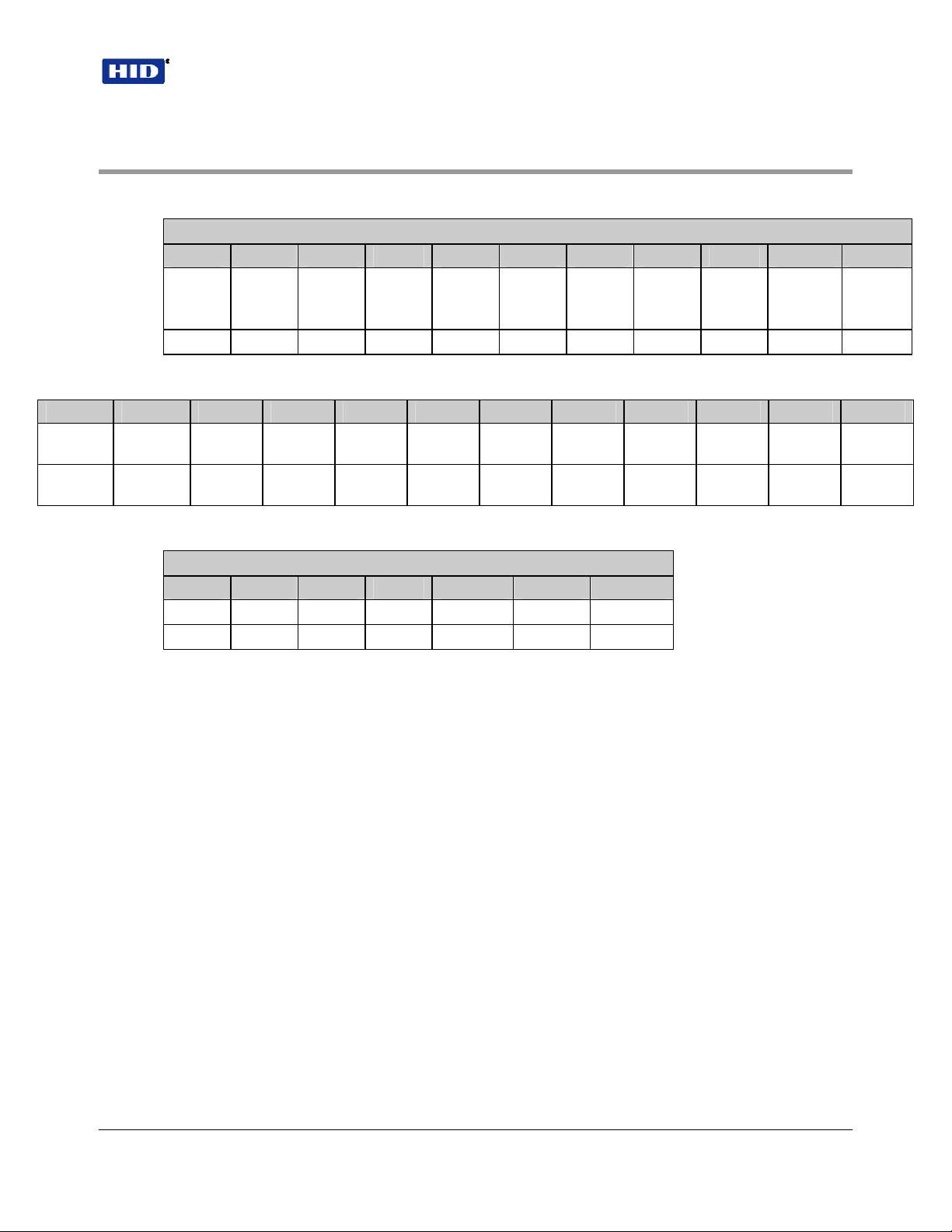
3.1 Standard Wire Connections
TB1
1 2 3 4 5 6 7 8 9 10 11
+DC Ground Data0/
Data
Red Black Green White Violet Orange Brown Yellow Blue -- --
3.2 Buffered Direct Wire Connections – Option D
10 11 E1 E2 E3 E4 E5 E6 E7 E8 E9 E10
Tamper
Common
Red /
Black
Tamper
Select
Red /
Green
+DC Ground Row 1 Row 2 Row 3 Row 4 Column 1 Column 2 Column 3 Select
White /
Red
White /
Black
Data1/
Clock
Gray Violet Red /
Shield
Ground
Green
LED
Yellow
Red
LED
Pink Tan White /
Beeper Hold/
Card
Present
Blue
Tamper
Common
White /
Green
Tamper
Select
Low
White /
Yellow
3.3 Direct Wire Connections – Option S
TB2
1 2 3 4 5 6 7
Row 1 Row 2 Row 3 Row 4 Column 3 Column 2 Column 1
Red Black Green White Drain Orange Brown
Notes:
1. When using 5 conductor cable, the power supply and Host must have a common ground (voltage
reference).
2. 6 conductor cable is required when controlling the red and green LED. (Alpha 1296 C or
equivalent)
3. 7 conductor cable is required when both green and red LED’s are controlled by the Host and the
power supply and Host "ground" are separate. (Alpha 1297 C or equivalent)
4. A 22 AWG twisted pair, shielded, stranded cable is often required for the tamper switch. Follow the
recommendations of the manufacturer of the Host system. If the tamper input is a supervised input
the "end of line" resistors may be mounted in the enclosure. Use extreme care and shield any bare
wire from the printed circuit assembly and its components.
5. The inner diameter of the cable fitting will accommodate a cable with an outer diameter of .300
inches (nominally).
6. Connect cable shield by connecting drain wire to TB1-2 ground. Leave foil and drain wire
disconnected at host end of cable by cutting them off at the end of the cable jacket.
7. When using the Buffered Direct Connect ProxPro with a 20 conductor cable, DC+ and Power (Red
and White / Red wires) must have a common connection to the host +DC power supply. The two
ground wires (Black and White / Black) must have a common ground connection to the host +DC
power supply.
February 22, 2007 Page 5 of 14
© 2007 HID Global Corporation. All rights reserved.
Loading...