


EH400-K
Table of contents
 Loading...
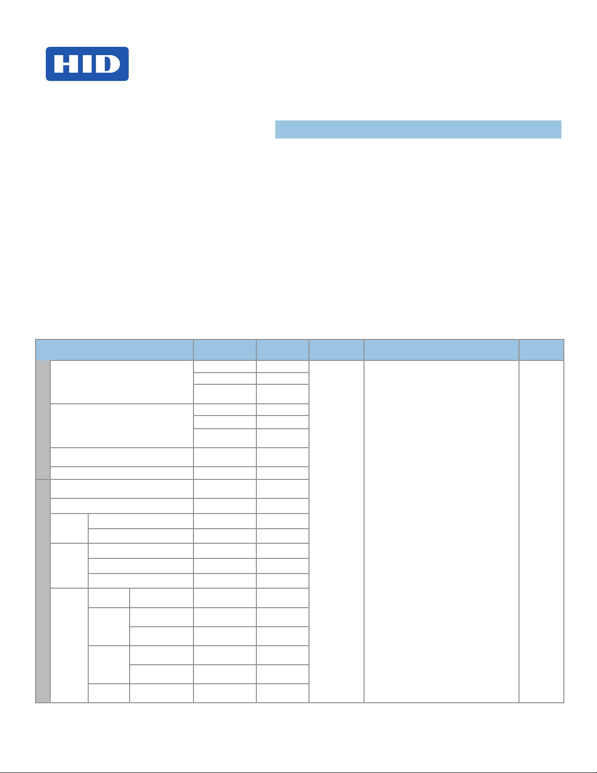
EDGE EVO
®
15370 Barranca Parkway
Irvine, CA 92618-2215
USA
Standard Networked Controller
EH400-K
InstallatIon GuIde
82000-921, Rev C.0
October 2011
© 2009 - 2011 HID Global Corporation. All rights reserved.
EDGE EVO is the next evolution in access control hardware solutions. A true IP solution that meets the demands of open architecture,
IP-centric environments, EDGE EVO provides fully distributed intelligence and decision making right to the door, leveraging the IT
infrastructure to the maximum extent possible. Leveraging Power-over-Ethernet (PoE), EDGE EVO reduces door installation costs by not
requiring a separate local power supply under many circumstances.
The Standard Networked Controller is a fully integrated single-door controller offering discrete I/O and Wiegand/Clock-and-Data interfaces
to readers. Additionally, connect native Hi-O devices (readers, locks, pushbuttons) and EDGE EVO Hi-O Modules to the Hi-O bus,
providing secure communication around the door. Hi-O involves devices with built-in intelligence and a CANbus that links all the devices
together. Password protect or encrypt Hi-O CANbus data trafc. Each Hi-O device (such as the REX switch, electric strike, card reader and
door operator) is connected to the CANbus by a single, four-wire cable. Two of the wires supply power and the other two are used for data
communication.
Specifications
CONDITIONS
DC Input (NSC)
DC Input (MAX)
Input
Supervised inputs
(AC, Batt, REX, Door Mon) (MAX)
Data 1/CLK , Data 0 / Data (MAX) 0-+5VDC Reference N/A
GRN LED, RED LED, Beep,
Hold (MAX)
External Tamper (MAX) +5VDC (NOM) 0.02
CAN DC
Output
(MAX)
Reader
DC PWR
Output
(MAX)
Ouput
Strike
/ AUX
Relays
NC or NO
DC Output
(MAX)
AUX 12 / 24VDC Input +10.8 to +24VDC 1.2Amp *
PoE Input + 24VDC (NOM) 0.4Amp *
AUX 12 VDC +9.8 to +12.25VDC 0.32Amp *
AUX 24VDC +9.8 to +12.25VDC 0.60Amp *
PoE Input +9.8 to +12.25VDC 0.58Amp *
AUX 12VDC
Input
AUX 24VDC
Input
PoE Input
AUX / PoE
Input
Unregulated (Wet)
Jumpers
Unregulated (Wet)
Jumpers
Regulated (Wet)
Jumpers - 12VDC
Unregulated (Wet)
Jumpers
Regulated (Wet)
Jumpers - 12VDC
Jumpers Set to Dry
VOLTAGE DC
(VDC)
+12VDC 0.18Amp
+24VDC 0.14Amp
PoE
(+48VDC NOM)
+12VDC 1.5Amp
+24VDC 1.5Amp
PoE
+48VDC (NOM)
0-+5VDC Reference 0.005Amp (sink)
0-+5VDC reference 0.005Amp (sink)
+10 to 12VDC 0.70Amp *
+23 to 24VDC 0.70Amp *
+10 to 12VDC 0.70Amp *
+16.5 to 24VDC 0.36Amp *
+10 to 12VDC 0.58Amp *
+12 to 24VDC
External
CURRENT
(Amp)
.085Amp
0.3Amp
2.00Amp **
OPERATING
TEMPERTURE
32° - 122°F
(0° - 50° C)
CABLE LENGTH
Hi-O CAN Bus Total Length 100 ft (30 m) -
22 AWG ● 0.65mm ● 0.33mm
Maximum between drops 30 ft (10 m)
22 AWG ● 0.65mm ● 0.33mm2
RJ45 328 ft (100 m) - Category 5 K
2
UL REF
NUMBER
KE400CxNN
x =
K for Black
G for Grey
NSC = Normal Standby Condition
* Combined output ratings, not to exceed 1.2 Amp
** Each Relay
Standard Networked Controller
Wi
n
D
o
o
r
P
S
w
M
a
g
ted
n
e
EH400-K
82000-921 C.0
1
Power Analysis
Before starting installation, determine which components will be used in the system and analyze the power requirements to avoid
over-loading the EDGE EVO Hi-O Networked Controller & Reader (EH400-K).
The steps that follow illustrate sizing power requirements for the system.
Step 1 - Identify System Components
Identify the components that will be used in the system. A typical installation may include the following components:
• Door Position Switch – Detects when the door is open or closed.
• Magnetic Lock – Holds the door locked.
• Request to Exit (REX) Switch – Unlocks the door when exiting the secured area.
• EDGE EVO Hi-O Standard Networked Controller (EH400-K) – Provides access control and manages all
peripherals around the door.
• iCLASS Wiegand Reader – Provides entry into the secured area.
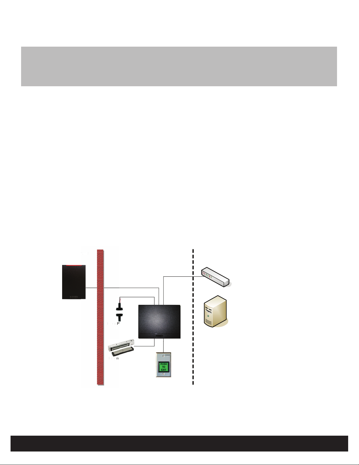
Step 2 - Create System Layout
Using the components identied in “Step 1 - Identify System Components” on page 2, create the system layout.
In this example, the EH400-K is connected to the remote server through an Ethernet connection and manages door
peripherals over the Hi-O bus. Controlling downstream door peripherals, the EH400-K is a fully integrated single-door
controller offering discrete I/O and Wiegand/Clock-and-Data interfaces to external readers. The EH400-K receives inputs
from the Door Position Switch and REX Switch to drive the Magnetic Lock output.
Unprotected
Area
Wiegand Ethernet Switch
ega
Wiegand Reader
Door Position
i
Switch
Magnetic Lock
Figure 1 - System Layout Example
Protected Area
REX Switch
Ethernet Data
EH400-K
Remote Area
Physical Access
Control Server
(real-time functions
not required )
INSTALLATION GUIDE
2
©2009 - 2011 HID Global Corporation. All rights reserved.
82000-921 C.0
Step 3 - Analyze Power Requirements
Standard Networked Controller
EH400-K
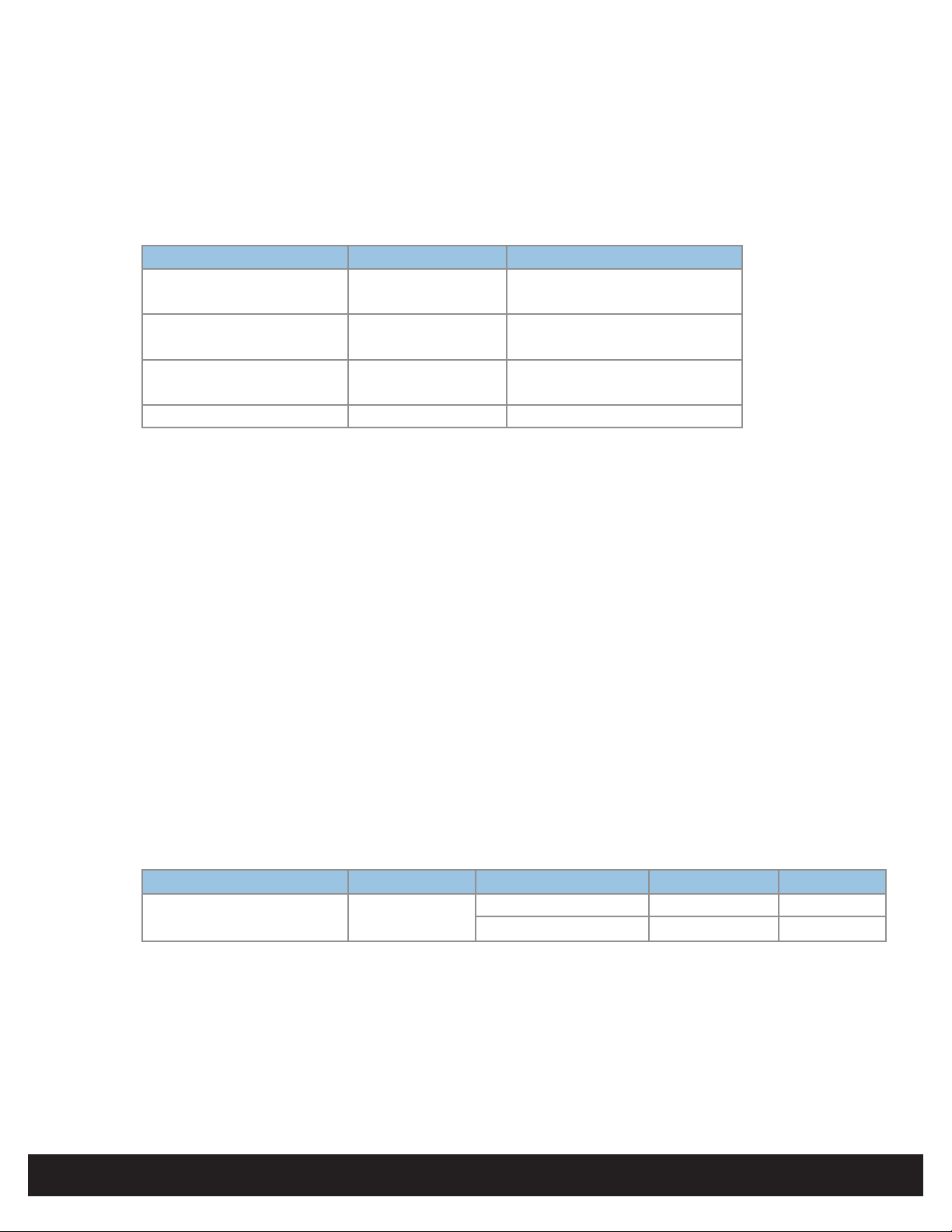
A - Door Peripheral Operational Currents
For the door peripherals identied in “Step 1 - Identify System Components” on page 2, consult the vendor data sheets
to determine the operational current draw. Typical operational current draw is provided below.
Note: See individual peripheral data sheets for actual operational current draw.
Device Conditions Typical Operational Current
Door Position Switch Vin = 12VDC 15mA
(For example, Securitron MSS) Vin = 24VDC 15mA
Mag Lock Vin = 12VDC 300mA
(For example, Securitron M32) Vin = 24VDC 150mA
REX Switch Vin = 12VDC 28mA
(For example, Securitron EEB) Vin = 24VDC 38mA
iCLASS Wiegand Reader Vin = 12VDC 150mA
B - Match I/O Requirements to the Hi-O Interface Device
For the door peripherals identied in “Step 1 - Identify System Components” on page 2, the system requires direct
connection to I/O interface and Wiegand/Clock-and-Data ports of the EH400-K. A separate Hi-O Interface Device is not
required.
C - Compute and Compare Overall Current Draw
Calculate the total current draw for all door peripherals and the attached Wiegand readers with the following equation,
adding terms as required.
I
= I
+ I
+ I
total
dps
mag
+ … + I
rex
iCLASS reader
The following calculations provide load current computations.
I
@ 12VDC = 15mA + 300mA + 28mA + 150mA = 493mA
total
I
@ 24VDC = 15mA + 150mA + 38mA + 150mA = 353mA
total
Compare the required current draw (I
select the Eh400-K power scheme. The CAN DC Pwr Output represents the entire power output capacity of the EH400-K.
Device Port Conditions Vout I out
Standard Networked Controller
(EH400-K)
In this example, the EH400-K provides sufcient power when operated with a PoE injector, or +12/24VDC auxiliary power
supplies.
Directly connect the door peripherals identied in “Step 1 - Identify System Components” on page 2 to the EH400-K I/O
ports per the “Specications” on page 1 for the selected input power scheme.
Ensure all door peripherals connected to the Strike/AUX relays and the Reader DC Pwr Output or both do not exceed
1.2Amps (AUX Input) or 0.4Amps (PoE Input), combined. Alternatively, the door peripherals may be connected to the Strike/
AUX relays congured for Dry contact up to 2Amps per relay.
CAN DC PWR
Output (MAX)
) to the output current capacity of the EH400-K (see Specication table, pg 1) to
total
AUX 12-24VDC Input +10.8 to +24VDC 1.2A
PoE input
+24VDC (NOM) 400mA
©2009 - 2011 HID Global Corporation. All rights reserved.
INSTALLATION GUIDE
3
Standard Networked Controller
EH400-K
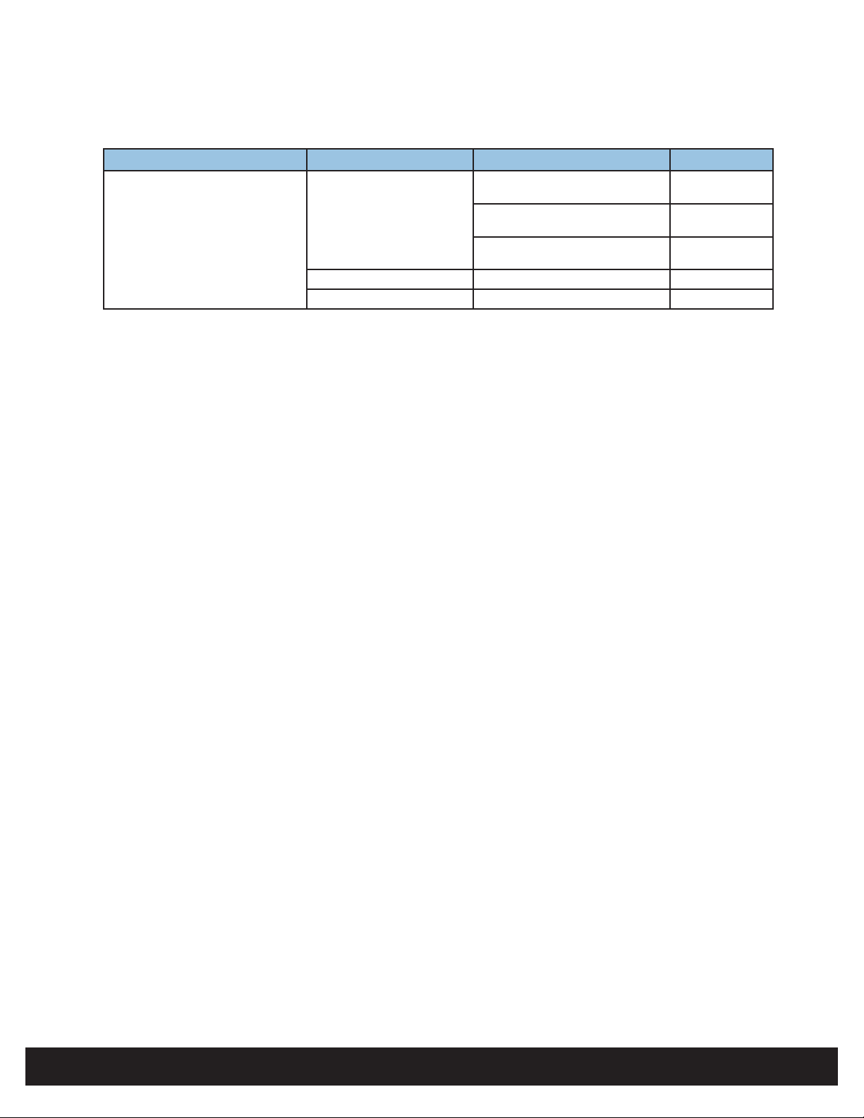
The door peripherals identied in “Step 1 - Identify System Components” on page 2 should be directly connected to the I/O
ports of the EH400-K. The I/O ports may be congured to provide the following output current capacity.
Device Ports Conditions I out
Strike / Aux
EDGE EVO Hi-O Standard Network
Controller (EH400-K)
* = Combined output ratings, not to exceed 1.2 Amp
** = Each relay
Ensure door peripherals connected to the Strike/AUX relays (regulated/unregulated) do not exceed 1.2 Amps combined.
Alternatively, the door peripherals may be connected to the Strike/AUX relays congured for Dry contact up to 2 Amps.
Ensure Wiegand / Clock-and-Data readers attached to the reader port do not exceed:
320mA @ +9.8VDC
or
600mA @ +12.25VDC
NC or NO
DC Output
Dry Jumpers +12VDC to +24VDC External 2.00 Amp**
Reader Power +9.8VDC to +12.25 VDC 320-600mA*
+12VDC unregulated
(@ +12VDC EDM-M input)
+24VDC unregulated
(@ +24VDC EDM-M input)
+12VDC regulated
(@ +24VDC EDM-M input)
82000-921 C.0
600 mA*
600 mA*
3 mA*
INSTALLATION GUIDE
4
©2009 - 2011 HID Global Corporation. All rights reserved.
Loading...