

Hickory N-5G User Manual
Installation Manual
Owner's Operating Manual
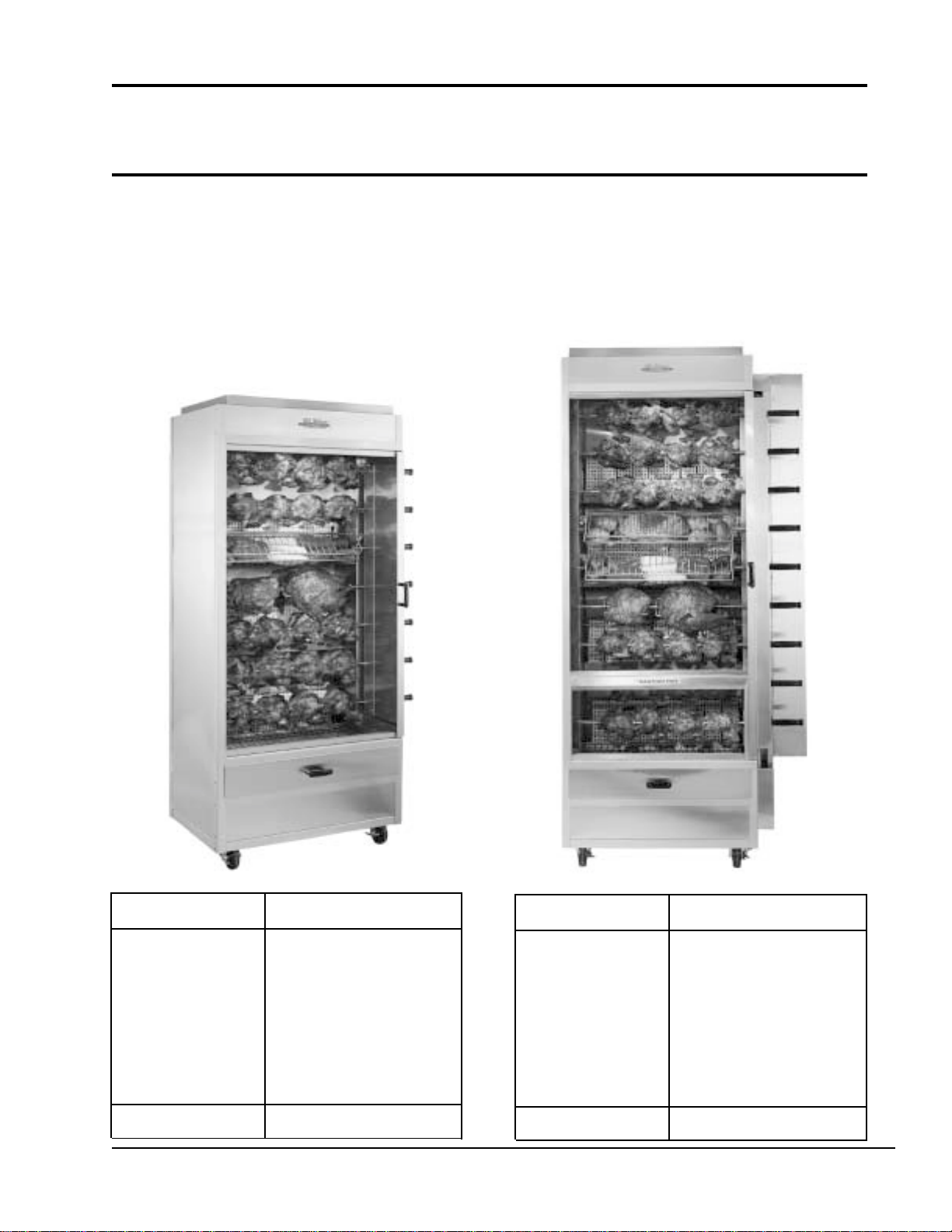
Hickory Rotisseries
Models: N/5G, N/7G and N/9G
USA
Machine T ype N / 5 G, N / 7 G
T otal Power Rating
Burner / Spits
Gas Categorie
Fittings
Ignition
Delivery Date:
120,000 BTU
3 Burners with 5 or 7 Spits
Natural Gas, LPG
3 Regulated Burners
3 Gas Pilot Lights
Final Inspection:
4900 Westside Avenue, North Bergen, New Jersey 07047
Machine T ype N / 9 G
T otal Power Rating
Burner / Spits
Gas Categorie
Fittings
Ignition
Delivery Date:
Tel: [201] 223-0050 Fax: [201] 223-0950
160,000 BTU
4 Burners with 9 Spits
Natural Gas, LPG
4 Regulated Burners
4 Gas Pilot Lights
Final Inspection:
Old Hickory Manual 12/00
Page 1 of 30

Table of Contents
1.0 Installation Instructions 3
1. 1 General Information 4
1. 2 Description of the Data Plate 4
1. 3 Machine Drawings and Dimensions 5
1. 4 Machine Dimensions 6
1. 5 Conversion and Adjustment Instructions 7
1. 6 Adjustments and V erification for use with Natural Gas 7
1. 7 Natural Gas Flow T able (Consumption) 7
1.7.1 Volumetric Method to Verify the High Flame Setting, Mathematical7
1. 8 Orifice Diameters, Primary Air Intake Settings, and Pressure Regulators 9
1. 9 Changing Gas Orifices 1 0
1.9.1 Changing the Main Gas Orifice 1 0
1.9.2 Changing the Pilot Gas Orifice 1 1
1.10 Checking the Connected Gas Pressure (Nominal Pressure) 1 2
1.11 Maintenance, Response to T echnical Problems, and Solutions 1 2
1.12 T esting or Checking for Safety 1 3
1.13 For Proper Operation 1 4
1.14 Description of the Electrical Connection 1 5
1.15 Electrical Diagram 1 5
1.16 Parts List for N/ 5G and N/ 7G with Diagrams 1 6
1.17 Parts List for N/ 9 G 21
2. 0 Operating Instructions 24
2. 1 Start up 2 4
2.2 Shut down 2 4
2. 3 Working with the Rotisserie 2 5
2.4 Cooking Times 26
2.5 Daily Cleaning 27
2.6 Cleaning Proceedures 28
2.7 Maintenance Proceedures 30
4900 Westside Avenue, North Bergen, New Jersey 07047
Tel: [201] 223-0050 Fax: [201] 223-0950
Old Hickory Manual 12/00
Page 2 of 30

1.0 Installation Instructions
a. When installing these units, it is important to comply with the most recently
established rules and regulations as deemed pertinent by the local and national
electrical, gas, ventilation, sanitation, and fire codes. These units are classified
by Underwriters Laboratories, Inc. as Gas-Fired Food Service Equipment in
accordance with American National Standards Institute ANSI Z83.1 1b-1991, Gas
Food Service Equipment - Ranges and Unit Boilers.
b . These gas units must not be directly connected to a gas flue or exhaust. However , the
units may only be operated inconjuction with a canopy type exhaust hood or a direct
flue vent.
c. The room where the units are being installed must be ventilated in accordance to
the valid codes and regulations.
d. The units are to be installed securely and horizontally . The units may be
installed on combustible floors. The units may be installed on adjustable legs or on
casters (wheels).
e . The minimum clearance to the rear or side walls must be 6 inches. The minimum
clearance between the hinged gas pipe cover on the spit handle side of the machine
and the side wall should be 24 inches for a sliding door and 10 inches for a hinged
door. It is also important to insure that the bottom of the units is kept clear so that
proper ventilation or air exchange can occur.
f. Normally , the units will be sent to the operator already set up for the particular
type of gas available at their location. However , unless otherwise specified, the
units will be set up for natural gas use. Before installing and using the units for the
first time, it is important to make sure that the gas type indicated on the data plate
matches the type of gas available in the location. Should this not be the case, it is
imperative to change or convert the units to the needed gas type.
g . The units must be fitted with the manual shut-off gas cock (valve) supplied with the
machine. This manual valve is needed to shut off the gas to the machine during
maintenance work, repairs, and if the unit needs to be disconnected for any reason.
h. A gas regulator is also supplied with the machine. This component is needed so that
the appropriate gas pressure can be set and insure an optimum operation of the unit.
i. Depending on local codes or if deemed necessary , a gas filter may also be required.
4900 Westside Avenue, North Bergen, New Jersey 07047
Tel: [201] 223-0050 Fax: [201] 223-0950
Old Hickory Manual 12/00
Page 3 of 30
1. 1 General Information
The Operating Instructions are to be given to the operator of the rotisserie. All unit
operators are to be familiar with the functions of the rotisserie.
The Operating Instructions should be kept in a location close to the rotisserie. It should be
easily recognizeable and easily accessible.
These rotisseries can be used with both natural and LPG gases. The rotisseries can be
converted or adjusted to any type of the locally distributed natural and LPG gases.
It is recommended that a repair and maintenance contract be signed with the
manufacturer's agent, distributor, or service agency .
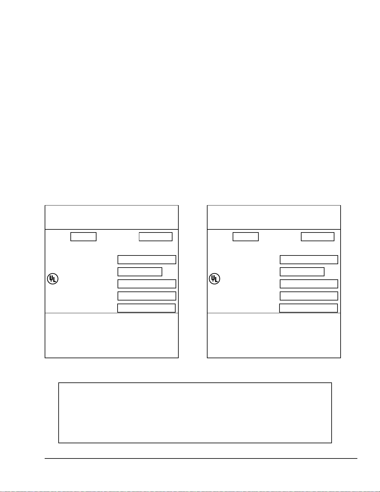
1. 2 Description of the Data Plate
HICKORY INDUSTRIES, INC.
COMMERCIAL COOKING APPLIANCES
NORTH BERGEN, NJ 07047
MODEL N/7G SERIAL NO.
MOTOR: 1 10 - 1 15 VOL TS 60 CYCLE AC CURRENT
1/3 HP SINGLE PHASE 1725 RPM
BURNERS 3
LISTED
GAS INPUT PER BURNER
MANIFOLD PRESSURE
69D6
TYPE OF GAS
MFG. DATE
MINIMUM INSTALLATION CLEARANCE
MAXIMUM LAMP WA TTAGE: 150 WATTS
FOR INSTALLATION ON A COMBUSTIBLE FLOOR
Gas-fired Food Service Equipment Classified by
Underwriters Laboratories Inc. In accordance with American
National Standards Institute ANSI Z 83.11b-1991, Gas Food
SIDE: 6 INCHES
BACK: 6 INCHES
Service Equipment-Ranges and Unit Boilers
40,000
5.5"
NA T
BTU/H
HICKORY INDUSTRIES, INC.
COMMERCIAL COOKING APPLIANCES
NORTH BERGEN, NJ 07047
MODEL N/9G SERIAL NO.
MOTOR: 1 10 - 1 15 VOL TS 60 CYCLE AC CURRENT
1/3 HP SINGLE PHASE 1725 RPM
BURNERS 4
LISTED
GAS INPUT PER BURNER
MANIFOLD PRESSURE
69D6
TYPE OF GAS
MFG. DATE
MINIMUM INSTALLATION CLEARANCE
MAXIMUM LAMP WA TTAGE: 150 WATTS
FOR INSTALLATION ON A COMBUSTIBLE FLOOR
Gas-fired Food Service Equipment Classified by
Underwriters Laboratories Inc. In accordance with American
National Standards Institute ANSI Z 83.11b-1991, Gas Food
SIDE: 6 INCHES
BACK: 6 INCHES
Service Equipment-Ranges and Unit Boilers
40,000
5.5"
NAT
BTU/H
WARNING!
This unit must be installed and connected in accordance to the latest regulations
and can only be operated in conjunction with forced ventilation or exhaust hood.
This unit has been designed for professional use only
and may only be installed or repaired by licensed service agencies!
Before installing or using this equipment, read these instructions!
4900 Westside Avenue, North Bergen, New Jersey 07047
Tel: [201] 223-0050 Fax: [201] 223-0950
Old Hickory Manual 12/00
Page 4 of 30
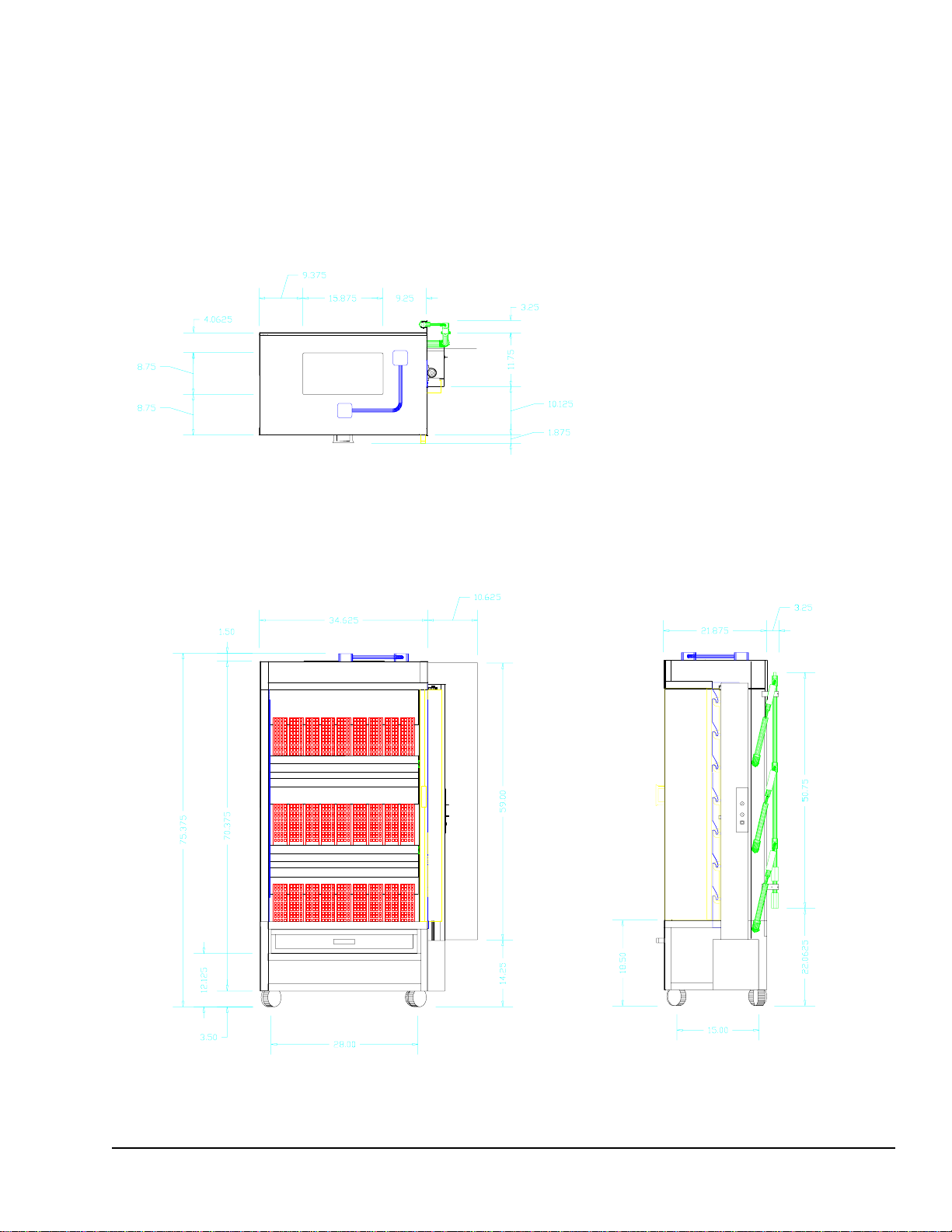
1.3 Machine Drawings and Dimensions
The following drawing of the Front View , Side View, and Top View indicate where the
dimensions are taken and should be used to plan the installation of the units.
N / 7 G
Top View
Front View Right Side View
4900 Westside Avenue, North Bergen, New Jersey 07047
Tel: [201] 223-0050 Fax: [201] 223-0950
Old Hickory Manual 12/00
Page 5 of 30
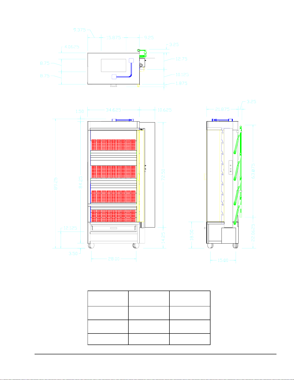
N / 9 G
Top View
Front View Right Side View
1.4 Main dimensions in inches
Height 75.38" 89.25"
Width 45.25"* 45.25"*
Depth 27.00" 27.00"
* Dimension include hinged gas pipe cover.
4900 Westside Avenue, North Bergen, New Jersey 07047
N / 5-7 G N / 9 G
Tel: [201] 223-0050 Fax: [201] 223-0950
Old Hickory Manual 12/00
Page 6 of 30
1.5 Conversion and Adjustment Instructions
Before converting or adjusting the machine, it is imperative that the manual gas cock be
turned to the "off" position. The electrical power to the machines should also be turned off.
When converting from one type of gas to another, the main gas orifice (or injector), the
pilot burner orifice (or injector), and the primary air adjustment must be changed according
to the table on page 9. In addition, the spring in the pressure regulator must be changed so
that it can operate at higher pressures.
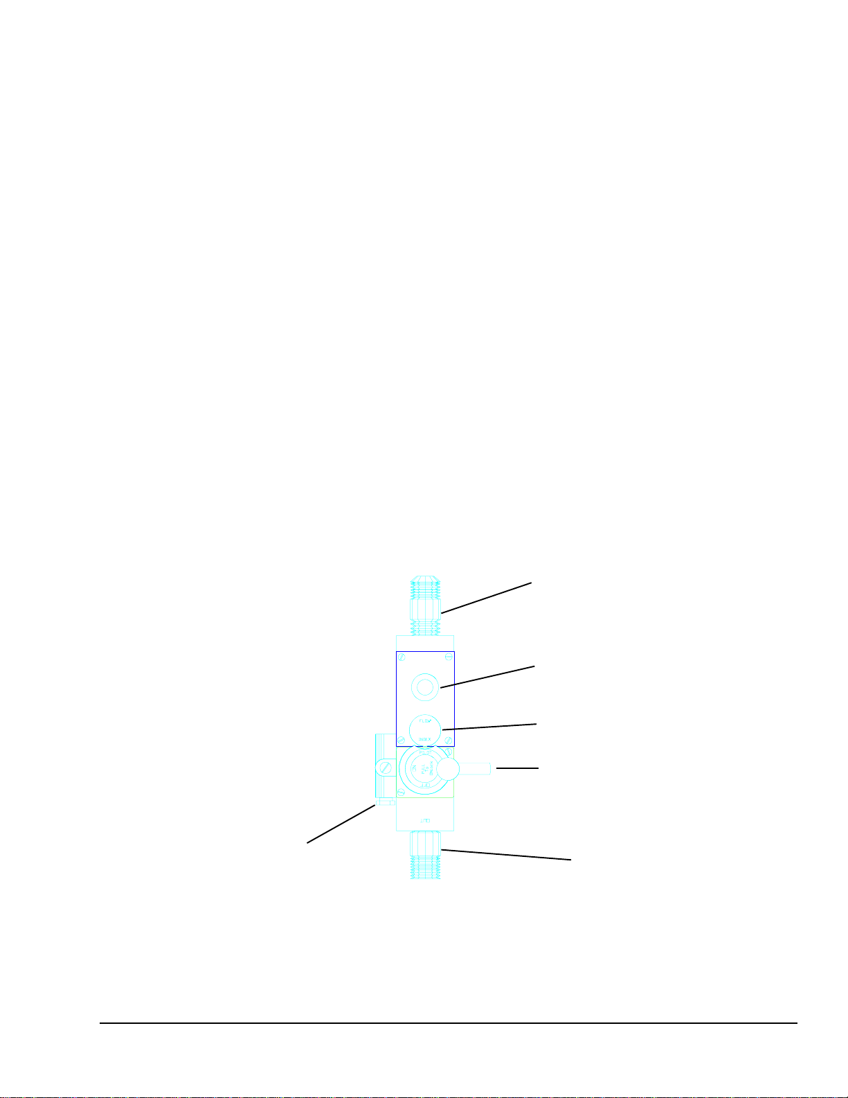
1. 6 Verification for use with Natural Gas
The highest flame setting ("on" position on the manifold gas valves) for each of the pipe
burners can be confirmed by using the volumetric method in conjunction with the main gas
meter. From the "pilot" position, turn the Gas Control Lever clock-wise, towards "on", until
the lever goes no further.
To carry out this verification procedure, it is necessary to obtain the heating value (BTU/ft3)
of the local gas from the local gas company.
If the measured gas volume does not correspond to the values in the following table, the
first item which should be checked is the incoming (connected) gas pressure. If the
pressure is correct, it must be verified that the proper size gas orifices are in place.
Pilot Gas Connection
Gas Line Input Connection
Thermocouple Connection
Flow Index Button
Gas Control Lever
(in Pilot position)
Gas Line Output
(connection to venturi)
Manifold V alve
4900 Westside Avenue, North Bergen, New Jersey 07047
Tel: [201] 223-0050 Fax: [201] 223-0950
Old Hickory Manual 12/00
Page 7 of 30

1. 7 Natural Gas Flow Table
Gas Flow
Gas
Heating Value in
BTU/ft³
per Burner (40,000 BTU)
in ft3/hr
High Flame Setting
Natural
Propane
Butane
1040 38.50
2500
2500
16.00
16.00
1.7.1 Volumetric Method to V erify the High Flame Setting, Mathematical
WARNING! No other gas equipment can be in operation during this procedure.
Calculation of flow rate E in ft3/hour
E = FP
H
i
E = Flow rate in ft3/minute
FP = High Flame Power setting in BTU/hr
Hi= Heating value in BTU/ft
Thus, for natural gas:
E = 40,000 BTU/hr = 38.50 ft3/hr = 0.64 ft3/min.
1040 BTU/ft
E = 0.64 ft3/min.
Calculation of the natural gas needed in 1 hour by a 9G (4 burners) at full power:
38.50 * 4 = 154 ft3/hr = 2.56 ft3/min.
The time and the flow measurements should be taken at the gas (flow) meter with a
chronometer (stop watch).
3
3
T o run the test, open the manual gas cock valve, start up the unit according to the start-up
instructions on page 24 and set the manifold valves to the high flame setting ("on" position).
Allow the unit to pre-heat (burn) for 10 to 15 minutes. Verify that the flow rate is calibrated
to the appropriate flow rate indicated in the table.
4900 Westside Avenue, North Bergen, New Jersey 07047
Tel: [201] 223-0050 Fax: [201] 223-0950
Old Hickory Manual 12/00
Page 8 of 30

1. 8 Orifice Diameters, Primary Air Intake Settings, and Pressure Regulators
T ype N / 5 G - N / 7 G
Burner Position from T op to Bottom
Gas / Pressure
inches W.C.
Natural / 5.5"
Propane / 11"
Butane / 11"
T ype N / 9 G
Main Orifice
Pilot Orifice
Primary Air Intake
Ø in drill size Orifice Marking in inches
3/16 "
#40
4211
1/8 "
1/8 "
#55
#55
3221
3221
3/16"
3/16"
Burner Position from T op to Bottom
Gas / Pressure Main Orifice
inches W.C.
Natural / 5.5"
Propane / 11"
Butane / 11"
Ø in drill size in inches
#40
#55
#55
Pilot Orifice
Orifice Marking
4211
3221
3221
Primary Air Intake
3/16 "
1/8 "
1/8 "
1/8 "
3/16"
3/16"
4900 Westside Avenue, North Bergen, New Jersey 07047
Tel: [201] 223-0050 Fax: [201] 223-0950
Old Hickory Manual 12/00
Page 9 of 30
 Loading...