

Hickory N-5.5G Service Manual
Hickory Industries, Inc.
Installation Manual
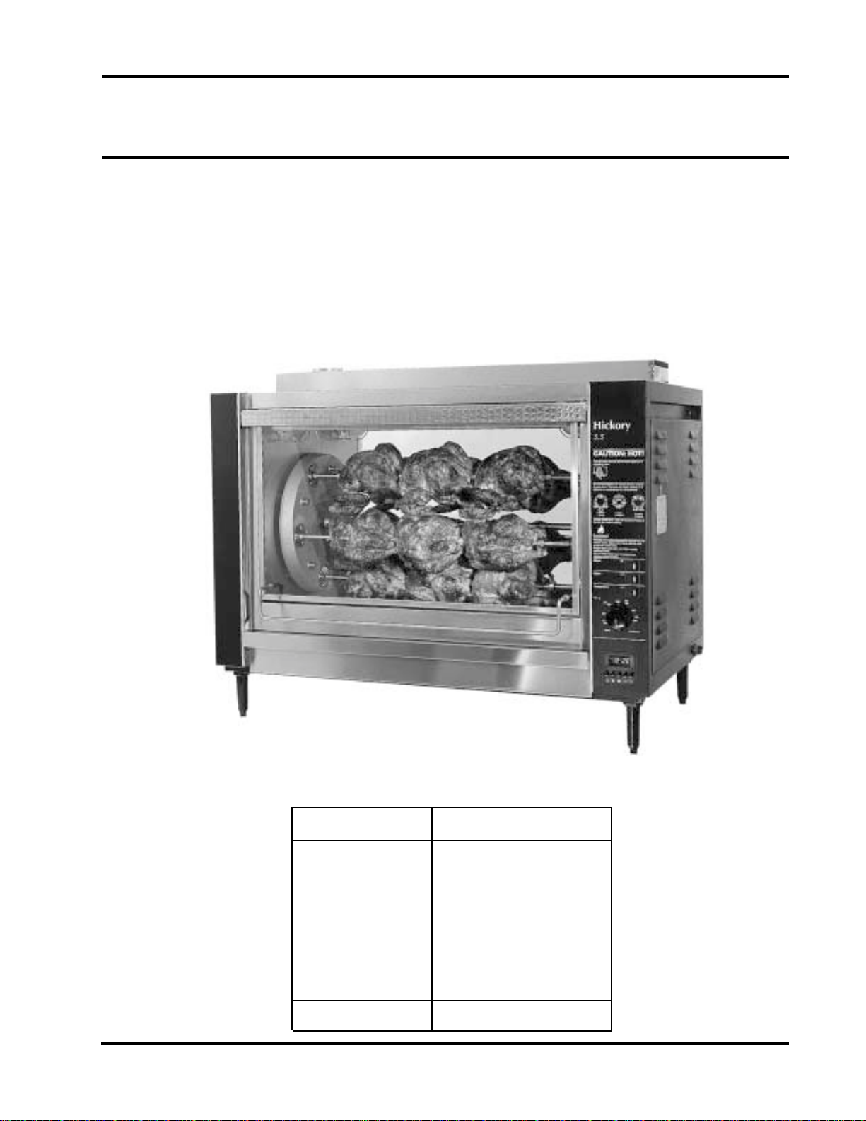
Hickory Rotisseries
Models: N/5.5 G
USA
Machine T ype N / 5. 5 G
T otal Power Rating
Burner / Spits
Gas Category
Fittings
Ignition
Delivery Date:
4900 Westside Avenue, North Bergen, New Jersey 07047
Tel: [201] 223-0050 Fax: [201] 223-0950
20,000 Btu
1 Burners with 5 Spits
Natural Gas, LPG
1 Infra-Red Gas Generators
1 Electronic Ignitor
Final Inspection:
N/5.5 Installation 8/5/97
Page 1 of 18

Hickory Industries, Inc.
Table of Contents
1.0 Installation Instructions 3
1. 1 General Information 4
1. 2 Description of the Data Plate 4
1. 3 Machine Drawings and Dimensions 5
1. 4 Conversion and Adjustment Instructions 6
1. 5 Adjustments and Verification for use with Natural Gas 6
1. 6 Natural Gas Flow T able (Consumption) 7
1.6.1 Volumetric Method to V erify the Flame Setting, Mathematical 7
1. 7 Orifice Diameters, Electronic Ignition Settings 8
1. 8 Changing Gas Orifices 8
1.8.1 Changing the Gas Orifice - Gas Generators 8
1.8.2 Changing the Gas Orifice - Pipe Burner 8
1 . 9 Ignition Cycle 8
1.10.1 Adjusting the Ignition Electrode 8
1.10 Checking the Connected Gas Pressure (Nominal Pressure) 9
1.10.1 Adjusting the Ignition Electrode 9
1.11 Maintenance, Response to T echnical Problems 10
1.12 Spit Drive Mechanism 1 1
1.12.1 Reasons for problems and solutions 1 2
1.13 Spit Drive Mechanism 1 3
1.14 T esting and Checking for Safety 1 4
1.15 Description of the Electrical Connection 1 4
1.16 Electrical Diagram 1 5
1.17 5.5 G Parts List 1 6
1.18 Exploded View Diagrams 1 8
4900 Westside Avenue, North Bergen, New Jersey 07047
Tel: [201] 223-0050 Fax: [201] 223-0950
N/5.5 Installation 8/5/97
Page 2 of 18

Hickory Industries, Inc.
1.0 Installation Instructions
a. When installing these units, it is important to comply with the most recently
established rules and regulations as deemed pertinent by the local and national
electrical, gas, ventilation, sanitation, and fire codes. These units are classified
by Underwriters Laboratories, Inc. as Gas-Fired Food Service Equipment in
accordance with American National Standards Institute ANSI Z83.1 1b-1991, Gas
Food Service Equipment - Ranges and Unit Boilers.
b . Gas units must not be directly connected to a gas flue or exhaust. However , both
electric and gas units may require operation in conjuction with a canopy type exhaust
hood if deemed necessary by local authorities.
c . The units must be installed in such a way that proper ventilation and heat exchange is
assured. The room must be ventilated in accordance to the valid codes and
regulations.
d . The units are to be installed securely and horizontally . The units may be installed on
combustible floors. The units must be installed with adjustable legs if placed on a
combustible surface.
e . The minimum clearance to the rear or side walls must be 13 inches. It is also
important to insure that the bottom of the units is kept clear so that proper ventilation
or air exchange can occur .
f. Normally , the units will be sent to the operator already set up for the particular
type of gas or electrical service available at their location. However, unless otherwise
specified, the gas units will be set up for natural gas use (including an electrical cord
for 120 V , 1 Phase, 60 Hz operation) and the electric units for 208 V , 3 Phase, 60 Hz
electrical use. Before installing and using the units for the first time, it is important to
make sure that the gas type and/or electrical power indicated on the data plate
matches the type of gas and electrical power available in the location. Should this not
be the case, it is imperative to change or convert the units to the needed types.
g. The gas units must be fitted with the manual shut-off gas cock (valve) and pressure
regulator supplied with the machine. This manual valve is needed to shut off the gas
to the machine during maintenance work, repairs, and if the unit needs to be
disconnected for any reason. The pressure regulator is needed to adjust the gas
pressure entering the unit to ensure the proper operation of the unit.
Electric units must be hard-wired or fitted with a power cord by a licensed electrician.
i. Depending on local codes or if deemed necessary , a gas filter may also be required
for gas units.
4900 Westside Avenue, North Bergen, New Jersey 07047
Tel: [201] 223-0050 Fax: [201] 223-0950
N/5.5 Installation 8/5/97
Page 3 of 18
1. 1 General Information
The Operating Instructions are to be given to the operator of the rotisserie. All unit
operators are to be familiar with the functions of the rotisserie.
The Operating Instructions should be kept in a location close to the rotisserie. It should be
easily recognizeable and easily accessible.
The gas rotisseries can be used with both natural and LPG gases. The rotisseries can be
converted or adjusted to any type of the locally distributed natural and LPG gases.
Electric units can be ordered to meet most electrical specifications.
It is recommended that a repair and maintenance contract be signed with the
manufacturer's agent, distributor, or service agency .
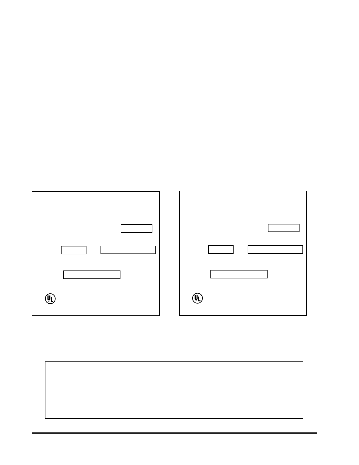
1. 2 Description of the Data Plate
Hickory Industries, Inc.
Hickory Industries, Inc.
Commercial Cooking Appliances
North Bergen, NJ 07047
Model: 5.5 G Serial No.
Motor: 110 - 115 V AC, 50/60 HZ, 3 RPM
Phase: 1
Manifold Pressure: 5" Natural or 10-11" Propane
BTU/H
LISTED
69D6
Gas: NA T
20,000
Minimum Installation Clearance
Sides: 13" Back: 13"
Maximum Lamp Wattage: 40 Watts
Burners: 1
Hickory Industries, Inc.
Commercial Cooking Appliances
North Bergen, NJ 07047
Model: 5.5 G Serial No.
Motor: 110 - 115 V AC, 50/60 HZ, 3 RPM
Phase: 1
Manifold Pressure: 5" Natural or 10-11" Propane
BTU/H
LISTED
69D6
Gas: LPG
17,000
Minimum Installation Clearance
Sides: 13" Back: 13"
Maximum Lamp Wattage: 40 Watts
WARNING!
This unit must be installed and connected in accordance to the latest regulations
and can only be operated in conjunction with forced ventilation or exhaust hood.
This unit has been designed for professional use only
and may only be installed or repaired by licensed service agencies!
Before installing or using this equipment, read these instructions!
Burners: 1
4900 Westside Avenue, North Bergen, New Jersey 07047
Tel: [201] 223-0050 Fax: [201] 223-0950
N/5.5 Installation 8/5/97
Page 4 of 18
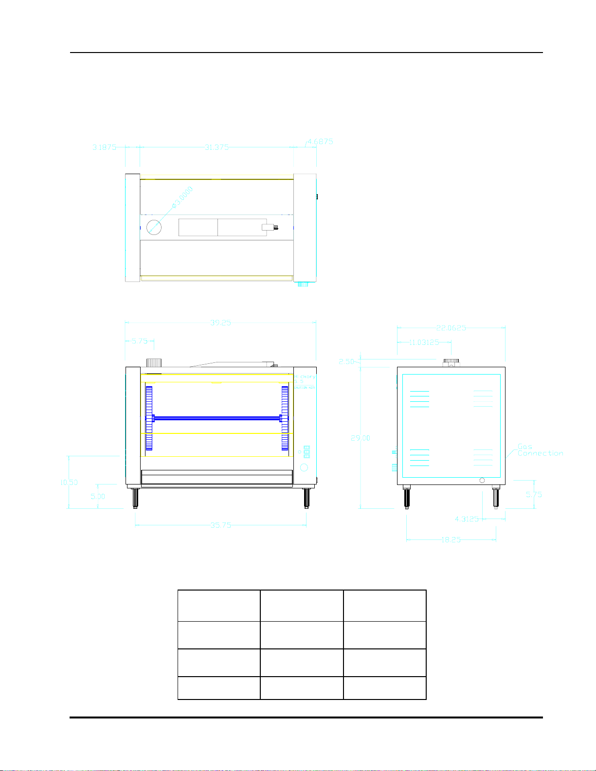
1.3 Machine Drawings and Dimensions
The following drawing of the Front View , Side View, and Top View indicate where the
dimensions are taken and should be used to plan the installation of the units.
N/ 5.5 G
Top View
Hickory Industries, Inc.
Front V iew Right Side View
N/ 5.5 G inches mm
Height 31.5" 800
Width 39.25" 997
Depth 22" 560
* Includes Gas Connection Attachments
4900 Westside Avenue, North Bergen, New Jersey 07047
Tel: [201] 223-0050 Fax: [201] 223-0950
N/5.5 Installation 8/5/97
Page 5 of 18

1.4 Gas Conversion and Adjustment Instructions
Before converting or adjusting the machine to another type of gas, it is imperative that the
manual gas cock be turned to the "off" position. The electrical power to the machines should
also be turned off. When converting the gas generators for use from one type of gas use to
another, the gas orifice (or injector) must be changed according to the table on page 8. In
addition, the spring in the pressure regulator supplied with the unit must be changed so that it
can operate at other gas pressures. Springs for the regulator can be ordered from Hickory
Industries.
1. 5 Verification for use with Natural Gas
The flame setting for the gas generator can be confirmed by using
the volumetric method in conjunction with the main gas meter. The burner has an
independent solenoid gas valve. The valve is controlled by an independent Gaslite
spark ignition module. The amount of gas flowing through the valve can not be adjusted
manually; there is only an "on" or "off" position.
T o carry out this verification procedure, it is necessary to obtain the heating value (BTU/ft3)
of the local gas from the local gas company .
Hickory Industries, Inc.
A variation in the heating value of the local gas from that on the table (1.6) will result in
a variation of the power output of the unit!
If the measured gas volume does not correspond to the values in the following table (1.6), the
items which should be checked are:
A. The incoming (connected) gas pressure while the burners and all other appliances
in the location are operational.
B. If the gas pressure is correct, it must be verified that the proper size gas orifices are in
place (see page 8).
Connection to Ignition
Module (Electrical)
Gas Output
(connection to burner)
Solenoid Valve
4900 Westside Avenue, North Bergen, New Jersey 07047
Tel: [201] 223-0050 Fax: [201] 223-0950
Gas Input
N/5.5 Installation 8/5/97
Page 6 of 18
 Loading...