


Maintenance and Service Guide
HP RP9 G1 Retail System

© Copyright 2016 HP Development Company,
L.P.
ENERGY STAR® is a registered mark owned by
the U.S. government. Microsoft and Windows
are either registered trademarks or trademarks
of Microsoft Corporation in the United States
and/or other countries.
The information contained herein is subject to
change without notice. The only warranties for
HP products and services are set forth in the
express warranty statements accompanying
such products and services. Nothing herein
should be construed as constituting an
additional warranty. HP shall not be liable for
technical or editorial errors or omissions
contained herein.
First Edition: February 2016
Document Part Number: 834296-001
Product notice
This guide describes features that are common
to most models. Some features may not be
available on your computer.
Not all features are available in all editions of
Windows 8. This computer may require
upgraded and/or separately purchased
hardware, drivers and/or software to take full
advantage of Windows 8 functionality. See
http://www.microsoft.com for details.
This computer may require upgraded and/or
separately purchased hardware and/or a DVD
drive to install the Windows 7 software and
take full advantage of Windows 7 functionality.
See http://windows.microsoft.com/en-us/
windows7/get-know-windows-7 for details.
Software terms
By installing, copying, downloading, or
otherwise using any software product
preinstalled on this computer, you agree to be
bound by the terms of the HP End User License
Agreement (EULA). If you do not accept these
license terms, your sole remedy is to return the
entire unused product (hardware and software)
within 14 days for a refund subject to the
refund policy of your place of purchase.
For any further information or to request a full
refund of the computer, please contact your
local point of sale (the seller).

Safety warning notice
WARNING! To reduce the possibility of heat-related injuries or of overheating the device, do not place
the device directly on your lap or obstruct the device air vents. Use the device only on a hard, at surface. Do
not allow another hard surface, such as an adjoining optional printer, or a soft surface, such as pillows or rugs
or clothing, to block airow. Also, do not allow the AC adapter to contact the skin or a soft surface, such as
pillows or rugs or clothing, during operation. The device and the AC adapter comply with the user-accessible
surface temperature limits dened by the International Standard for Safety of Information Technology
Equipment (IEC 60950-1).
iii

iv Safety warning notice

Table of contents
1 Product overview .......................................................................................................................................... 1
Standard features .................................................................................................................................................. 1
Unfolding the ergonomic stand ............................................................................................................................. 3
Rear components ................................................................................................................................................... 4
2 Illustrated parts catalog ................................................................................................................................ 5
Computer major components ................................................................................................................................ 5
Optional displays and USB devices ........................................................................................................................ 7
Cables and adapters .............................................................................................................................................. 8
Storage devices ...................................................................................................................................................... 9
Misc parts ............................................................................................................................................................. 10
3 Routine care, SATA drive guidelines, and disassembly preparation .................................................................. 11
Electrostatic discharge information .................................................................................................................... 11
Generating static ............................................................................................................................... 11
Preventing electrostatic damage to equipment ............................................................................... 12
Personal grounding methods and equipment .................................................................................. 12
Grounding the work area ................................................................................................................... 12
Recommended materials and equipment ........................................................................................ 13
Routine care and maintenance ............................................................................................................................ 13
Drivers and rmware ......................................................................................................................... 13
Operating guidelines ......................................................................................................................... 13
Environmental specications ............................................................................................................ 14
Before you begin ............................................................................................................................... 14
Cleaning the computer case .............................................................................................................. 14
Cleaning the monitor or touch screen ............................................................................................... 15
Cleaning I/O ports and fan area ......................................................................................................... 15
Cleaning the keyboard ....................................................................................................................... 15
Cleaning the mouse ........................................................................................................................... 15
Cleaning the MSR ............................................................................................................................... 16
Service considerations ......................................................................................................................................... 16
Power supply fan ............................................................................................................................... 16
Tools and software Requirements .................................................................................................... 16
Screws ............................................................................................................................................... 16
Cables and connectors ...................................................................................................................... 16
Hard Drives ........................................................................................................................................ 17
v

Lithium coin cell battery .................................................................................................................... 17
SATA hard drives .................................................................................................................................................. 17
SATA hard drive cables ......................................................................................................................................... 18
SATA data cable ................................................................................................................................. 18
SMART ATA drives ................................................................................................................................................ 18
Cable management .............................................................................................................................................. 18
4 Removal and replacement procedures ........................................................................................................... 19
Preparation for disassembly ............................................................................................................................... 19
Installing a port cover .......................................................................................................................................... 20
Removing and attaching the ergonomic and compact stands ........................................................................... 21
Routing cables (ergonomic stand) ....................................................................................................................... 24
Routing cables (compact stand) .......................................................................................................................... 24
Removing and replacing the power supply (ergonomic stand) .......................................................................... 25
Rear cover and shield ........................................................................................................................................... 28
Installing an optional HP integrated USB barcode scanner, magnetic strip reader (MSR), biometric
reader, or webcam ............................................................................................................................................... 29
Installing an optional HP integrated USB module on the sides or top of the display head ............. 29
Installing an optional HP integrated USB barcode scanner on the bottom of the display head ..... 31
Installing a 2 x 20 LCD or 7” LCD customer facing display (CFD) ......................................................................... 32
Installing a top mount CFD ................................................................................................................ 32
Installing a bottom mount CFD ......................................................................................................... 33
Installing memory ............................................................................................................................................... 35
DDR4-SDRAM SODIMMs .................................................................................................................... 35
Removing and installing a SODIMM .................................................................................................. 36
Removing and installing a 2.5-inch hard drive ................................................................................................... 37
Removing and installing an M.2 storage device .................................................................................................. 39
Replacing the battery .......................................................................................................................................... 41
WLAN module ...................................................................................................................................................... 42
Hard drive bracket ............................................................................................................................................... 43
VESA mount bracket ............................................................................................................................................ 44
Heat sink .............................................................................................................................................................. 46
Processor ............................................................................................................................................................. 47
Fan ........................................................................................................................................................................ 48
Rear trim .............................................................................................................................................................. 49
USB port ............................................................................................................................................................... 50
Speakers .............................................................................................................................................................. 51
Antennas .............................................................................................................................................................. 52
System board ....................................................................................................................................................... 53
System board callouts ....................................................................................................................... 56
Display panel assembly ....................................................................................................................................... 57
vi

Power board ......................................................................................................................................................... 59
5 Conguring the software .............................................................................................................................. 60
Touch screen calibration ...................................................................................................................................... 60
Calibration for Windows 7 Professional and Embedded POSReady 7 .............................................. 60
Calibration for Windows 8.1 Professional and Embedded 8.1 Industry Pro Retail .......................... 60
Calibration for Windows 10 Professional and Windows 10 IoT Enterprise for Retail ...................... 60
Conguring all optional HP integrated USB peripheral modules (HP integrated USB barcode scanner,
magnetic strip reader (MSR), biometric reader, or webcam)
Conguring powered serial ports ........................................................................................................................ 61
6 Computer Setup (F10) Utility ........................................................................................................................ 62
Computer Setup (F10) Utilities ............................................................................................................................ 62
Using Computer Setup (F10) Utilities ................................................................................................ 62
Computer Setup–Main ....................................................................................................................... 64
Computer Setup—Security ............................................................................................................... 66
Computer Setup—Advanced ............................................................................................................. 68
Recovering the Conguration Settings ............................................................................................................... 73
.............................................................................. 61
7 POST error messages and diagnostic front panel LEDs and audible codes ......................................................... 74
POST numeric codes and text messages ............................................................................................................. 74
Interpreting system validation diagnostic front panel LEDs and audible codes ................................................ 79
8 Password security and resetting CMOS .......................................................................................................... 81
Resetting the password jumper .......................................................................................................................... 81
Changing a Setup or Power-On password ........................................................................................................... 82
Deleting a Setup or Power-On password ............................................................................................................ 83
Clearing and resetting the CMOS ......................................................................................................................... 83
9 Using HP PC Hardware Diagnostics (UEFI) ....................................................................................................... 85
Downloading HP PC Hardware Diagnostics (UEFI) to a USB device .................................................................... 85
10 Troubleshooting without diagnostics .......................................................................................................... 87
Safety and comfort .............................................................................................................................................. 87
Before you call for technical support .................................................................................................................. 87
Helpful hints ........................................................................................................................................................ 88
Solving retail system-specic problems ............................................................................................................. 89
Solving general problems .................................................................................................................................... 90
Solving hard drive problems ................................................................................................................................ 94
Solving audio problems ....................................................................................................................................... 97
vii

Solving printer problems ..................................................................................................................................... 99
Solving hardware installation problems ........................................................................................................... 100
Solving Network Problems ................................................................................................................................ 101
Solving memory problems ................................................................................................................................ 104
Solving USB ash drive problems ..................................................................................................................... 105
Solving Internet access problems ..................................................................................................................... 106
Solving software problems ............................................................................................................................... 108
11 System backup and recovery ..................................................................................................................... 109
Backing up, restoring, and recovering in Windows 10 ...................................................................................... 109
Creating recovery media and backups ............................................................................................ 109
Creating HP Recovery media (select products only) .................................................... 109
Using Windows tools ....................................................................................................................... 111
Restore and recovery ...................................................................................................................... 111
Recovering using HP Recovery Manager ...................................................................... 111
What you need to know before you get started ........................................ 111
Using the HP Recovery partition (select products only) ............................ 112
Using HP Recovery media to recover ......................................................... 112
Changing the computer boot order ............................................................ 113
Removing the HP Recovery partition (select products only) ..................... 113
Backing up, restoring, and recovering in Windows 8.1, Windows 8, or Industry 8.1 ....................................... 113
Creating recovery media and backups ............................................................................................ 113
Restoring and recovering using Windows tools ............................................................................. 114
Using Reset when the system is not responding ......................................................... 114
Recovery using the Windows recovery USB ash drive ............................................... 115
Recovery using Windows operating system media (purchased separately) ............... 115
Backing up, restoring, and recovering in Windows 7 and POSReady 7 ............................................................ 116
Creating recovery media ................................................................................................................. 116
Creating recovery media using HP Recovery Manager (select models only) ............... 117
Creating recovery discs with HP Recovery Disc Creator (select models only) ............. 117
Creating recovery discs .............................................................................. 118
Backing up your information ........................................................................................ 118
System Restore ............................................................................................................................... 119
System Recovery ............................................................................................................................. 119
System Recovery when Windows is responding .......................................................... 120
System Recovery when Windows is not responding .................................................... 120
System Recovery using recovery media (select models only) ..................................... 121
Using HP Recovery Disc operating system discs (select models only) ........................ 121
Appendix A Power cord set requirements ....................................................................................................... 123
General requirements ........................................................................................................................................ 123
viii

Japanese power cord requirements .................................................................................................................. 123
Country-specic requirements .......................................................................................................................... 124
Appendix B Specications ............................................................................................................................. 125
Index ........................................................................................................................................................... 126
ix

x

1 Product overview
Standard features
The HP RP9 G1 Retail System includes the following features.
●
Integrated All-in-One (AiO) form factor
●
Designed for long-term deployment within general retail, hospitality, and other markets
●
15.6” (Model 9015) and 18.5” (Model 9018) base models with Projected Capacitive touch technology
and 1366 x 768 resolution
●
VESA mounting holes (100 mm x 100 mm)
●
Choice of ergonomic stand, compact stand, or no stand (Display Head unit only)
●
Optional Integrated HP peripherals:
◦
Integrated magnetic strip reader (left mount or right mount options, encryption capable)
◦
2 x 20 LCD customer facing display (rear top mount or bottom mount with extension arm)
◦
7" LCD customer facing display (rear top mount or bottom mount with extension arm)
◦
Two integrated barcode scanners (one with left mount or right mount options, and one bottom
mount only)
◦
Integrated webcam (top mount only)
◦
Integrated biometric ngerprint reader (left mount or right mount options)
●
DDR4 2133 MHz Memory, up to 32GB maximum RAM
●
Operating system choices:
◦
Embedded 8.1 Industry ProRetail 64-bit
◦
FreeDos 2.0
◦
POSReady 7 32-bit
Standard features 1

◦
POSReady 7 64-bit
◦
Windows 10 IoT Enterprise for Retail 64-bit
◦
Windows 10 Pro 64-bit
◦
Windows 10 Pro downgrade to Windows 7 Pro 32-bit
◦
Windows 10 Pro downgrade to Windows 7 Pro 64-bit
◦
Windows 10 Pro downgrade to Windows 8.1 Pro 64-bit
◦
Windows 7 Professional Edition 32-bit
◦
Windows 7 Professional Edition 64-bit
◦
Windows 8.1 Pro 64-bit
●
One M.2 slot for optional WLAN
●
Two USB 2.0 ports and two USB 3.0 ports
●
One 24V powered USB port and three 12V powered USB ports, two powered serial ports, and one cash
drawer port
●
Audio line-in and line-out ports
●
One DisplayPort for secondary display
●
One 2.5” internal storage bay for SATA HDD or SSD
●
Two M.2 internal storage bays
●
Cable management features
●
ENERGY STAR compliant
2 Chapter 1 Product overview

Unfolding the ergonomic stand
If your model includes an ergonomic stand, the system is shipped with the stand in the folded position. Follow
the steps below to unfold the stand.
1. Unfold the stand to the desired position.
2. Route the DC power cord through the cable retainer and connect the cord to the rear I/O power
connector.
Unfolding the ergonomic stand 3
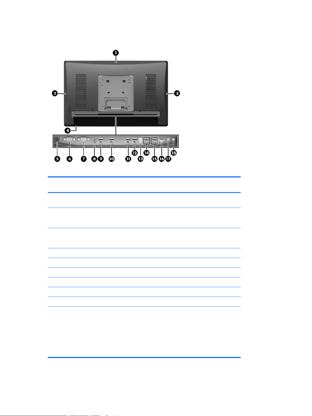
Rear components
ItemDescription ItemDescription
1 Top USB port for optional HP integrated USB
webcam, 7” CFD, or 2 x 20 CFD (behind rear cover)
2 Side USB port for optional HP integrated USB
barcode scanner, MSR, or biometric reader
(behind rear cover)
3 Side USB port for optional HP integrated USB
barcode scanner, MSR, or biometric reader
(behind rear cover)
4 Power button 13 Cash drawer connector
5 DC In power connector 14 USB 2.0 ports
6 Powered serial port (COM A) 15 USB 3.0 ports
7 Powered serial port (COM B) 16 RJ-45 network connector
8 DisplayPort (for secondary display) 17 Audio line in connector
9 Powered USB 12V (A) 18 Audio line out connector
NOTE: The powered serial ports can be congured for 0V, 5V, or 12V.
NOTE: The 24-volt Powered USB connector and the 12-volt Powered USB connector are keyed dierently as
a precaution to prevent connection errors.
NOTE: The cash drawer connector is covered by a sticker that must be removed to connect the cash drawer
cable.
CAUTION: The cash drawer connector is similar in size and shape to a modem jack. To avoid damage to the
computer, DO NOT plug a network cable into the cash drawer connector.
10 Powered USB 12V (B) used if the optional
bottom mount barcode scanner is installed
11 Powered USB 12V (C)
12 Powered USB 24V
4 Chapter 1 Product overview

2 Illustrated parts catalog
NOTE: HP continually improves and changes product parts. For complete and current information on
supported parts for your computer, go to http://partsurfer.hp.com, select your country or region, and then
follow the on-screen instructions.
Computer major components
Item Description
(1) System board (includes replacement thermal material)
(2) Rear plastic trim
15.6- inch models
18.5 inch models
(3) Rear cover
15.6-inch models
Computer major components 5

Item Description
18.5-inch models
(4) VESA bracket plastic cover
(5) Power supply, 230W
Standard
Slim
(6) Display panel assembly (includes touch board that is pre-programmed to the touch glass)
15.6-inch models
18.5-inch models
(7) Memory modules (SODIMM, PC4-17000, CL15)
16 GB
8 GB
4 GB
Stand
(8) Ergonomic
(9) Compact
*
Processor (not illustrated)
Intel Core i7-6700
Intel Core i5-6500
Intel Core i3-6100
Intel Pentium G4400
Intel Celeron G3900
*
not illustrated
6 Chapter 2 Illustrated parts catalog
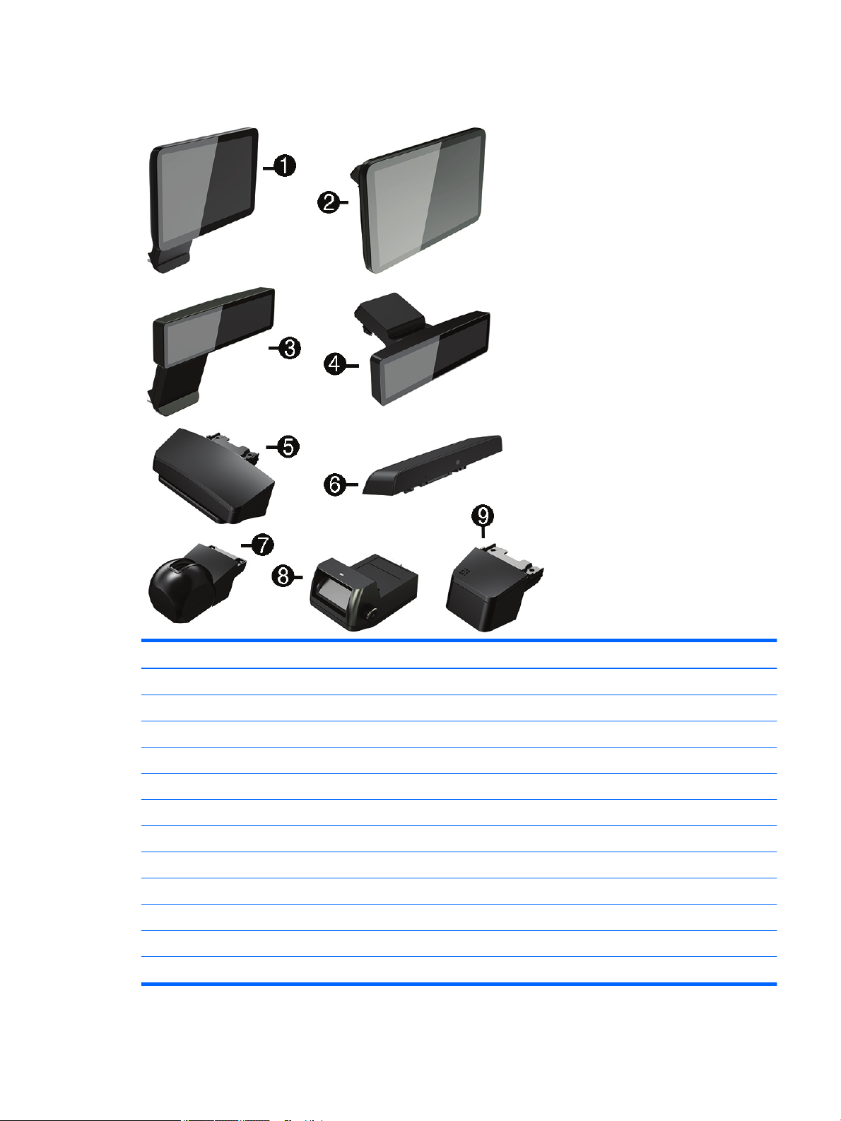
Optional displays and USB devices
Item Description
HP Retail Integrated 7-inch Customer Facing Display (with arm)
(1) Bottom mount
(2) Top mount
HP Retail Integrated 2x20 Display (with arm)
(3) Bottom mount
(4) Top mount
(5) HP Integrated Single-Head MSR
(6) HP Retail Integrated Webcam
HP Integrated Bar Code Scanner
(7) Left/right
(8) Bottom
(9) HP Integrated Fingerprint Reader
Optional displays and USB devices 7

Cables and adapters
Description
USB board cable
Right, 15.6-inch
Left, 15.6-inch
Right, 18.5-inch
Left, 18.5-inch
Top, 18.5-inch
Hard drive connector and cable
Antennas and transceivers
Left
Right
Power board cable
15.6-inch
18.5-inch
DisplayPort cable
Adapters
USB to serial
DisplayPort to VGA
DisplayPort to DVI
DisplayPort to HDMI 1.4
8 Chapter 2 Illustrated parts catalog
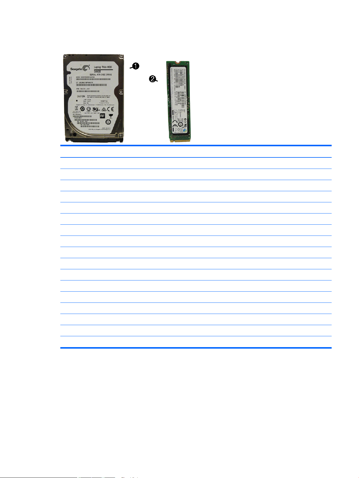
Storage devices
Item Description
(1) Hard drives, 2.5-inch
1 TB, hybrid SSD
500 GB, 7200 rpm, 2.5-inch, self-encrypting
500 GB, 7200 rpm, 2.5-inch
*
Solid-state drives, 2.5-inch (not illustrated)
256 GB Solid-state drive
128 GB Solid-state drive
128 GB Solid-state drive, self-encrypting (SED)
120 GB Solid-state drive
64-GB, ash, MLC
(2) Solid-state drives, M.2
256 MB, PCIe
256 MB, PCIe, NVMe
256 MB
128 MB, PCIe
128 MB, PCIe, NVMe
128 MB
*
not illustrated
Storage devices 9

Misc parts
Item Description
(1) Heat sink
(2) Speakers
15.6-inch models
18.5-inch models
(3) Fan
(4) Power board
(5) USB port
(6) WLAN module
802.11 a/b/g/n + Bluetooth 4.0, 2x2
802.11 a/b/g/n + Bluetooth 4.0, 2x2 (for use only in Indonesia)
Intel Dual Band Wireless-AC 8260
*
*
*
*
*
*
*
not illustrated
Foot kit (includes rubber foot and screw)
Pad lock
I/O cover
Top port cover
Side port cover
Plug cover
10 Chapter 2 Illustrated parts catalog

3 Routine care, SATA drive guidelines, and
disassembly preparation
This chapter provides general service information for the computer. Adherence to the procedures and
precautions described in this chapter is essential for proper service.
CAUTION: When the computer is plugged into an AC power source, voltage is always applied to the system
board. You must disconnect the power cord from the power source before opening the computer to prevent
system board or component damage.
Electrostatic discharge information
A sudden discharge of static electricity from your nger or other conductor can destroy static-sensitive
devices or microcircuitry. Often the spark is neither felt nor heard, but damage occurs. An electronic device
exposed to electrostatic discharge (ESD) may not appear to be aected at all and can work perfectly
throughout a normal cycle. The device may function normally for a while, but it has been degraded in the
internal layers, reducing its life expectancy.
Networks built into many integrated circuits provide some protection, but in many cases, the discharge
contains enough power to alter device parameters or melt silicon junctions.
Generating static
The following table shows that:
●
Dierent activities generate dierent amounts of static electricity.
●
Static electricity increases as humidity decreases.
Relative Humidity
Event 55% 40% 10%
Walking across carpet
Walking across vinyl oor
Motions of bench worker
Removing DIPs from plastic tube
Removing DIPs from vinyl tray
Removing DIPs from Styrofoam
Removing bubble pack from PCB
Packing PCBs in foam-lined box
These are then multi-packaged inside plastic tubes, trays, or Styrofoam.
7,500 V
3,000 V
400 V
400 V
2,000 V
3,500 V
7,000 V
5,000 V
15,000 V
5,000 V
800 V
700 V
4,000 V
5,000 V
20,000 V
11,000 V
35,000 V
12,000 V
6,000 V
2,000 V
11,500 V
14,500 V
26,500 V
21,000 V
NOTE: 700 volts can degrade a product.
Electrostatic discharge information 11

Preventing electrostatic damage to equipment
Many electronic components are sensitive to ESD. Circuitry design and structure determine the degree of
sensitivity. The following packaging and grounding precautions are necessary to prevent damage to electric
components and accessories.
●
To avoid hand contact, transport products in static-safe containers such as tubes, bags, or boxes.
●
Protect all electrostatic parts and assemblies with conductive or approved containers or packaging.
●
Keep electrostatic sensitive parts in their containers until they arrive at static-free stations.
●
Place items on a grounded surface before removing them from their container.
●
Always be properly grounded when touching a sensitive component or assembly.
●
Avoid contact with pins, leads, or circuitry.
●
Place reusable electrostatic-sensitive parts from assemblies in protective packaging or conductive
foam.
Personal grounding methods and equipment
Use the following equipment to prevent static electricity damage to equipment:
●
Wrist straps are exible straps with a maximum of one-megohm ± 10% resistance in the ground cords.
To provide proper ground, a strap must be worn snug against bare skin. The ground cord must be
connected and t snugly into the banana plug connector on the grounding mat or workstation.
●
Heel straps/Toe straps/Boot straps can be used at standing workstations and are compatible with
most types of shoes or boots. On conductive oors or dissipative oor mats, use them on both feet with
a maximum of one-megohm ± 10% resistance between the operator and ground.
Static Shielding Protection Levels
Method Voltage
Antistatic plastic
Carbon-loaded plastic
Metallized laminate
Grounding the work area
To prevent static damage at the work area, use the following precautions:
●
Cover the work surface with approved static-dissipative material. Provide a wrist strap connected to the
work surface and properly grounded tools and equipment.
●
Use static-dissipative mats, foot straps, or air ionizers to give added protection.
●
Handle electrostatic sensitive components, parts, and assemblies by the case or PCB laminate. Handle
them only at static-free work areas.
●
Turn o power and input signals before inserting and removing connectors or test equipment.
1,500
7,500
15,000
●
Use xtures made of static-safe materials when xtures must directly contact dissipative surfaces.
●
Keep work area free of nonconductive materials such as ordinary plastic assembly aids and Styrofoam.
●
Use eld service tools, such as cutters, screwdrivers, and vacuums, that are conductive.
12 Chapter 3 Routine care, SATA drive guidelines, and disassembly preparation

Recommended materials and equipment
Materials and equipment that are recommended for use in preventing static electricity include:
●
Antistatic tape
●
Antistatic smocks, aprons, or sleeve protectors
●
Conductive bins and other assembly or soldering aids
●
Conductive foam
●
Conductive tabletop workstations with ground cord of one-megohm +/- 10% resistance
●
Static-dissipative table or oor mats with hard tie to ground
●
Field service kits
●
Static awareness labels
●
Wrist straps and footwear straps providing one-megohm +/- 10% resistance
●
Material handling packages
●
Conductive plastic bags
●
Conductive plastic tubes
●
Conductive tote boxes
●
Opaque shielding bags
●
Transparent metallized shielding bags
●
Transparent shielding tubes
Routine care and maintenance
This chapter describes how to clean the computer, monitor, keyboard, and mouse of your retail point of sales
system. Dust and other particles can accumulate on or inside the computer and accessories. These particles
can scratch hardware components and can cause overheating, shortening the life of the computer. Cleaning
the computer removes this potentially damaging buildup and helps prolong the life of the computer. HP
recommends that you inspect your system for cleanliness once a month as part of a regular maintenance
program.
Drivers and rmware
HP recommends that you regularly download and install the latest drivers and rmware updates to help
enhance computer performance, resolve known issues, and avoid replacing parts unnecessarily.
Please go to http://www.hp.com/support to download and install the latest drivers and BIOS updates for your
specic Retail Point of Sale model.
Operating guidelines
Follow these guidelines to prevent overheating and to help prolong the life of the computer:
●
Keep the computer away from excessive moisture, direct sunlight, and extremes of heat and cold.
●
Place the computer on a sturdy, level surface.
●
Leave an area at least 10.2 cm (4 in) wide all around the computer and above the monitor clear to permit
the ow of air in and out of the computer.
Routine care and maintenance 13

●
Do not operate the computer with the cover or side panel removed.
●
Do not stack computers on top of each other or place computers so near one another that they are
subject to each other’s re-circulated or preheated air.
●
If you are operating the computer within a separate enclosure, the enclosure must have intake and
exhaust ventilation. The same operating guidelines listed previously still apply.
●
Keep liquids away from the computer and keyboard.
●
Do not block or cover any intake and exhaust vents, this restrict the airow into the computer.
●
Do not place the keyboard, with the keyboard feet down, directly against the front of the computer as
this also restricts airow.
●
Occasionally, clean the air vents. Lint, dust, and other foreign matter can block the vents and limit the
airow. Be sure to unplug the computer before cleaning the air vents.
●
Install or enable power management functions of the operating system or other software, including
sleep states
Environmental specications
This table describes the average environmental conditions for Retail Systems.
Specication Description
Temperature Operating: 10° to 40°C (50° to 104°F)
Non-operating: -22° to 149° F (-30° to 65° C)
Relative humidity Operating: 20% to 85%
Maximum altitude (unpressurized) Operating: 3048 m (10,000 ft)
Please visit http://h10025.www1.hp.com/ewfrf/wc/siteHome?lc=en&cc=us to view the specications for
other retail platform models.
Before you begin
Before you begin cleaning the computer and components, perform these steps to reduce the risk of electrical
shock:
1. Turn o the computer and monitor.
2. Unplug the power cord from the computer and monitor.
Cleaning the computer case
Follow these steps to clean the computer case.
1. Use a clean, dry cloth to dust the computer case.
2. Use a clean, lint-free cloth or swab dampened with water to remove light stains or dirt.
Non-operating: 0% to 95% (non-condensing at ambient)
Non-operating: 9144 m (30,000 ft)
NOTE: For stubborn stains, use isopropyl (rubbing) alcohol. You do not need to rinse the case
afterwards as the alcohol evaporates quickly and does not leave a residue.
14 Chapter 3 Routine care, SATA drive guidelines, and disassembly preparation

3. Wipe the computer with a clean, lint-free cloth.
4. Use a battery-powered vacuum to remove dust and buildup from the vents.
Cleaning the monitor or touch screen
Follow these steps to clean the monitor or touch screen.
CAUTION: Do not clean the monitor using the following chemicals and materials:
●
Petroleum based materials such as benzene or thinner
●
Alcohol (ethyl, methyl, or isopropyl)
●
Abrasive material
●
Any volatile substance
1. Spray a small amount of a mild glass cleaner onto a lint-free soft cloth.
2. Wipe the surface and each side of the display to remove any dirt, ngerprints, or other debris.
CAUTION: Avoid wiping in the top corners where the optics are located.
3. Use a dry, soft, lint-free cloth to wipe the screen dry after cleaning.
4. Clean the display cabinet using a clean soft cloth that is lightly dampened with a mild detergent.
Cleaning I/O ports and fan area
The computer has a series of ports, usually in the back. Dust and debris can collect in these ports, this can
reduce connectivity and performance. Use a battery-powered vacuum to remove any debris that has
accumulated in and around these ports.
NOTE: Unplug the computer before cleaning the I/O ports and fan.
Cleaning the keyboard
Follow these steps to clean the keyboard.
CAUTION: Use safety glasses equipped with side shields before cleaning debris from under the keys.
1. Disconnect the keyboard from the computer.
2. Use a battery-powered vacuum to gently remove debris particles that get between and beneath the
keyboard keys. Use a low setting to avoid removing key caps and springs.
You can also use canned, pressurized air to clean debris from under the keys.
CAUTION: Too much air pressure can dislodge lubricants applied under the wide keys.
3. Use a clean, dry cloth and isopropyl alcohol to clean the buildup on the keyboard keys.
Cleaning the mouse
Follow these steps to clean an optical mouse.
1. Unplug the mouse from the computer.
2. Wipe the body of the mouse with cleaning wipes or a cloth and cleanser.
Routine care and maintenance 15

3. Turn the mouse body upside down.
4. Clean the LED bulb and the surrounding area on the bottom of the mouse with a cotton swab dampened
with isopropyl alcohol.
Cleaning the MSR
Swipe a standard cleaning card through the MSR a couple of times to clean the MSR (magnetic strip reader).
You can order a standard cleaning card online. Alternately, you can create a cleaning card by putting a thin, oil
free cloth around a credit card.
Service considerations
Listed below are some of the considerations that you should keep in mind during the disassembly and
assembly of the computer.
Power supply fan
The power supply fan is a variable-speed fan based on the temperature in the power supply.
CAUTION: The cooling fan is always on when the computer is in the “On” mode. The cooling fan is o when
the computer is in “Standby,” “Suspend,” or “O” modes.
You must disconnect the power cord from the power source before opening the computer to prevent system
board or component damage.
Tools and software Requirements
To service the computer, you need the following:
●
Torx T-15 screwdriver
●
Flat-bladed screwdriver (may sometimes be used in place of the Torx screwdriver)
●
Phillips #2 screwdriver
●
Diagnostics software
●
Tamper-resistant T-15 wrench
Screws
The screws used in the computer are not interchangeable. They may have standard or metric threads and may
be of dierent lengths. If an incorrect screw is used during the reassembly process, it can damage the unit. HP
strongly recommends that all screws removed during disassembly be kept with the part that was removed,
then returned to their proper locations.
CAUTION: Metric screws have a black nish. U.S. screws have a silver nish and are used on hard drives only.
CAUTION: As each subassembly is removed from the computer, it should be placed away from the work area
to prevent damage.
Cables and connectors
Most cables used throughout the unit are at, exible cables. These cables must be handled with care to
avoid damage. Apply only the tension required to seat or unseat the cables during insertion or removal from
the connector. Handle cables by the connector whenever possible. In all cases, avoid bending or twisting the
16 Chapter 3 Routine care, SATA drive guidelines, and disassembly preparation

cables, and ensure that the cables are routed in such a way that they cannot be caught or snagged by parts
being removed or replaced.
CAUTION: When servicing this computer, ensure that cables are placed in their proper location during the
reassembly process. Improper cable placement can damage the computer.
Hard Drives
Handle hard drives as delicate, precision components, avoiding all physical shock and vibration. This applies
to failed drives as well as replacement spares.
●
●
●
●
●
●
●
If a drive must be mailed, place the drive in a bubble-pack mailer or other suitable protective packaging
and label the package “Fragile: Handle With Care.”
Do not remove hard drives from the shipping package for storage. Keep hard drives in their protective
packaging until they are actually mounted in the computer.
Avoid dropping drives from any height onto any surface.
If you are inserting or removing a hard drive, turn o the computer. Do not remove a hard drive while the
computer is on or in standby mode.
Before handling a drive, ensure that you are discharged of static electricity. While handling a drive, avoid
touching the connector.
Do not use excessive force when inserting a drive.
Avoid exposing a hard drive to liquids, temperature extremes, or products that have magnetic elds
such as monitors or speakers.
Lithium coin cell battery
The battery that comes with the computer provides power to the real-time clock and has a minimum lifetime
of about three years.
See the appropriate removal and replacement chapter for the chassis you are working on in this guide for
instructions on the replacement procedures.
WARNING! This computer contains a lithium battery. There is a risk of re and chemical burn if the battery is
handled improperly. Do not disassemble, crush, puncture, short external contacts, dispose in water or re, or
expose it to temperatures higher than 140ºF (60ºC). Do not attempt to recharge the battery.
NOTE: Batteries, battery packs, and accumulators should not be disposed of together with the general
household waste. In order to forward them to recycling or proper disposal, please use the public collection
system or return them to HP, their authorized partners, or their agents.
SATA hard drives
Serial ATA Hard Drive Characteristics
Number of pins/conductors in data cable 7/7
Number of pins in power cable 15
Maximum data cable length 39.37 in (100 cm)
Data interface voltage dierential 400-700 mV
Drive voltages 3.3 V, 5 V, 12 V
SATA hard drives 17

Serial ATA Hard Drive Characteristics
Jumpers for conguring drive N/A
Data transfer rate 6.0 Gb/s
SATA hard drive cables
SATA data cable
Always use an HP approved SATA 6.0 Gb/s cable as it is fully backwards compatible with the SATA 1.5 Gb/s
drives.
Current HP desktop products ship with SATA 6.0 Gb/s hard drives.
SATA data cables are susceptible to damage if overexed. Never crease a SATA data cable and never bend it
tighter than a 30 mm (1.18 in) radius.
The SATA data cable is a thin, 7-pin cable designed to transmit data for only a single drive.
SMART ATA drives
The Self Monitoring Analysis and Recording Technology (SMART) ATA drives for the HP Personal Computers
have built-in drive failure prediction that warns the user or network administrator of an impending failure or
crash of the hard drive. The SMART drive tracks fault prediction and failure indication parameters such as
reallocated sector count, spin retry count, and calibration retry count. If the drive determines that a failure is
imminent, it generates a fault alert.
Cable management
Always follow good cable management practices when working inside the computer.
●
Keep cables away from major heat sources like the heat sink.
●
Do not jam cables on top of expansion cards or memory modules. Printed circuit cards like these are not
designed to take excessive pressure on them.
●
Keep cables clear of sliding or moveable parts to prevent them from being cut or crimped when the parts
are moved.
●
When folding a at ribbon cable, never fold to a sharp crease. Sharp creases may damage the wires.
●
Some at ribbon cables come prefolded. Never change the folds on these cables.
●
Do not bend any cable sharply. A sharp bend can break the internal wires.
●
Never bend a SATA data cable tighter than a 30 mm (1.18 in) radius.
●
Never crease a SATA data cable.
●
Do not rely on components like the drive cage, power supply, or computer cover to push cables down
into the chassis. Always position the cables to lay properly by themselves.
18 Chapter 3 Routine care, SATA drive guidelines, and disassembly preparation

4 Removal and replacement procedures
NOTE: HP continually improves and changes product parts. For complete and current information on
supported parts for your computer, go to http://partsurfer.hp.com, select your country or region, and then
follow the on-screen instructions.
Adherence to the procedures and precautions described in this chapter is essential for proper service. After
completing all necessary removal and replacement procedures, run the Diagnostics utility to verify that all
components operate properly.
NOTE: Not all features listed in this guide are available on all computers.
Preparation for disassembly
See Routine care, SATA drive guidelines, and disassembly preparation on page 11 for initial safety procedures.
1. Remove/disengage any security devices that prohibit opening the computer.
2. Shut down the computer properly through the operating system, then turn o any external devices.
3. Disconnect the power cord from the power outlet.
CAUTION: Regardless of the power-on state, voltage is always present on the system board as long as
the system is plugged into an active AC outlet. You must disconnect the power cord and wait
approximately 30 seconds for the power to drain to avoid damage to the internal components of the
computer.
4. Disconnect all cables from the rear I/O connectors.
CAUTION: The screws used in the computer are of dierent thread sizes and lengths; using the wrong screw
in an application may damage the unit.
NOTE: During disassembly, label each cable as you remove it, noting its position and routing. Keep all
screws with the units removed.
Preparation for disassembly 19

Installing a port cover
To install the port cover, snap the port cover onto the rear panel over the ports (1) and secure it with the
screw (2).
20 Chapter 4 Removal and replacement procedures

Removing and attaching the ergonomic and compact stands
The RP9 can be attached to a wall, swing arm, pole-mounted bracket, or other mounting xture by removing
the stand (when ordered attached to the system unit). The RP9 supports the VESA industry standard 100 mm
spacing between mounting holes.
This apparatus is intended to be supported by UL or CSA Listed wall mount bracket. HP recommends that you
use an HP Quick Release mounting bracket for wall mounting (part number EM870AA).
CAUTION: To attach a third-party mounting solution to the RP9, four 4 mm, 0.7 pitch, and 10 mm long
screws are required. Longer screws must not be used because they may damage the system. It is important to
verify that the manufacturer’s mounting solution is compliant with the VESA standard and is rated to support
the weight of the system.
Follow the steps below to remove the stand, mount the RP9 to a wall mount or swing arm, and to install the
stand.
1. Prepare the computer for disassembly (Preparation for disassembly on page 19).
2. To remove the ergonomic stand, lay the RP9 face down on a at surface covered by a soft clean cloth.
Push up the release latch on the rear of the display head (1), tilt the stand back (2), and then lift up from
the display (3).
Removing and attaching the ergonomic and compact stands 21

3. To remove the compact stand, lay the RP9 face down on a at surface covered by a soft clean cloth. Push
up the release latch on the rear of the display head (1), tilt the stand back (2), and then lift up from the
display (3).
4. To mount the display head to a wall or swing arm, use the 100 mm x 100 mm VESA mounting holes on
the rear of the display head.
22 Chapter 4 Removal and replacement procedures

5. To attach the ergonomic stand, lay the RP9 face down on a at surface covered by a soft clean cloth.
Slide the tabs on the top of the stand mount into the slots on the display head (1), and then rotate the
bottom of the stand mount down onto the display head so that it snaps in place (2).
6. To attach the compact stand, lay the RP9 face down on a at surface covered by a soft clean cloth. Slide
the tabs on the top of the stand mount into the slots on the display head (1), and then rotate the bottom
of the stand mount down onto the display head so that it snaps in place (2).
Removing and attaching the ergonomic and compact stands 23

Routing cables (ergonomic stand)
To route cables through the ergonomic stand:
1. Prepare the computer for disassembly (Preparation for disassembly on page 19).
2. Connect the cables to the appropriate rear connectors.
NOTE: Tilt the display head back for easy access to the rear connectors.
3. Route the cables from the connectors on the rear panel through the cable retainer on the neck of the
(1), and then through the hole in the center of the base and out the underside of the base (2).
stand
4. Reconnect the power cord and press the power button.
Routing cables (compact stand)
To route cables through the compact stand:
1. Prepare the computer for disassembly (Preparation for disassembly on page 19).
2. Connect the cables to the appropriate rear connectors.
NOTE: Tilt the display head back for easy access to the rear connectors.
3. Snap o the cable routing cover on the neck of the stand (1).
4. Route the cables from the connectors on the rear panel down the neck of the stand, and then through
the hole in the center of the base and out the underside of the base (2).
24 Chapter 4 Removal and replacement procedures

5. Snap the cable routing cover onto the neck of the stand to cover the cables (3).
6. Reconnect the power cord and press the power button.
Removing and replacing the power supply (ergonomic stand)
Description
Power supply, 230W, standard
Power supply, 230W, slim
To remove and replace the power supply:
1. Prepare the computer for disassembly (Preparation for disassembly on page 19).
2. Unplug the DC power cable from the connector on the rear of the display head.
3. Pull up on the center of the cover on the right side of the base and rotate the cover upward.
Removing and replacing the power supply (ergonomic stand) 25

4. Pull up on the center of the cover on the left side of the base and rotate the cover upward.
5. Lay the RP9 face down on a at surface covered by a soft clean cloth. Lift the pull tab and loosen the
screw on the bottom plate of the stand (1), then lift the bottom of the plate up (2), and then pull the
plate o the stand (3).
26 Chapter 4 Removal and replacement procedures

6. Unplug the AC power cord from the side of the power supply (1), and then lift the power supply out of
the stand’s base (2).
7. Route the xed side of the new power supply’s power cord through the hole in the center of the base and
connect it to the DC power connector on the rear panel (1). Place the new power supply into the stand’s
base (2), and then connect the AC power cord to the side of the power supply (3) and route the cord
through the retainer slot on the base.
8. Reassemble the stand.
Removing and replacing the power supply (ergonomic stand) 27

Rear cover and shield
To remove the rear cover and shield:
1. Prepare the computer for disassembly (Preparation for disassembly on page 19)
2. Press the two rear cover latches outward (1). Slide the rear cover up, and then lift it o the display head
(2).
3. Use the nger slots on the rear metal shield to pull the top of the shield up, and then lift the shield o
the display head.
To install a rear cover and shield, reverse the removal procedures.
28 Chapter 4 Removal and replacement procedures

Installing an optional HP integrated USB barcode scanner,
magnetic strip reader (MSR), biometric reader, or webcam
Only install HP approved integrated USB modules designed for these USB ports. The USB ports do not support
optical drives or hard drives.
The integrated barcode scanner, integrated MSR, and integrated biometric reader can be installed on the left
or right side of the display head. The integrated webcam can only be installed on the top of the display head.
There is a separate integrated barcode scanner that can be installed on the bottom of the display head.
Installing an optional HP integrated USB module on the sides or top of the display head
The procedure for installing a module is the same for all modules, whether it is on the left side, the right side,
or the top of the display head.
1. Prepare the computer for disassembly (Preparation for disassembly on page 19).
2. Remove the rear cover (Rear cover and shield on page 28).
3. Remove the two screws that secure the port cover (1), and then pull the port cover o the display head
(2).
NOTE: You may need to gently loosen the port cover from inside of the screw holes with a at
screwdriver.
Installing an optional HP integrated USB barcode scanner, magnetic strip reader (MSR), biometric reader,
or webcam
29

4. Insert the USB connector on the module into the USB port (1), and then secure the module with the two
screws that were previously removed (2).
5. Reassemble the computer.
If you install a new MSR, it needs to be congured with the system settings using HP USB Mini Magnetic Stripe
Reader (MSR) Conguration Software. Use the following procedure to congure the new CSR.
1. Connect the old MSR (the one being replaced).
2. Start HP magnetic stripe reader conguration utility (http://h20564.www2.hp.com/hpsc/swd/public/
detail?swItemId=ir_125989_1&swEnvOid=4047).
3. Retrieve the conguration details from the old MSR and save.
4. Connect the new MSR (the replacement).
5. Write the saved conguration to the new MSR.
30 Chapter 4 Removal and replacement procedures

Installing an optional HP integrated USB barcode scanner on the bottom of the display head
To install an integrated USB barcode scanner:
1. Prepare the computer for disassembly (Preparation for disassembly on page 19).
2. Slide the cover on the barcode scanner down and then lift the cover up to remove it (1). Plug the barcode
scanner into the rear I/O Powered USB 12V (B) connector (2), and then secure the barcode scanner with
the screw provided (3). Replace the barcode scanner cover (4).
3. Reconnect all cables to the rear I/O connectors.
4. Reconnect the power cord and press the power button.
Installing an optional HP integrated USB barcode scanner, magnetic strip reader (MSR), biometric reader,
or webcam
31

Installing a 2 x 20 LCD or 7” LCD customer facing display (CFD)
A short extension arm CFD can be attached to the top of the display head or a long extension arm CFD can be
attached to the bottom of the stand’s base. The procedure for installing a CFD is the same, whether it is a 2 x
20 or 7” LCD.
Installing a top mount CFD
To install a top mount CFD:
1. Prepare the computer for disassembly (Preparation for disassembly on page 19).
2. Remove the rear cover (Rear cover and shield on page 28).
3. Remove the two screws that secure the top port cover (1), and then pull the port cover o the display
head (2).
NOTE: You may need to gently loosen the port cover from inside of the screw holes with a at
screwdriver.
4. Align the tabs on the rear cover with the slots on the display head while placing the cover on the display
head, and then slide the cover down so that it snaps in place.
32 Chapter 4 Removal and replacement procedures

5. Remove the cover from the CFD arm by pulling back the top of the cover (1) and then the bottom of the
cover. Insert the USB connector on the CFD into the USB port (2), and then secure the CFD with the screw
provided (3). Replace the arm cover (4) by snapping on the top of the cover and then the bottom of the
cover.
6. Reconnect all cables to the rear I/O connectors.
7. Reconnect the power cord and press the power button.
Installing a bottom mount CFD
To install a bottom mount CFD:
1. Prepare the computer for disassembly (Preparation for disassembly on page 19).
2. Unplug the power cable from the connector on the rear of the display head.
3. Lay the RP9 face down on a at surface covered by a soft clean cloth.
4. Slide the CFD bracket onto the underside of the base (1), and then secure the bracket with the screw (2).
Installing a 2 x 20 LCD or 7” LCD customer facing display (CFD) 33

5. Route the CFD cable up through the center hole in the base and connect it to a USB port on the rear I/O.
6. Reconnect the power cord and press the power button.
34 Chapter 4 Removal and replacement procedures

Installing memory
Description
Memory modules (SODIMM, PC4-17000, CL15)
16 GB
8 GB
4 GB
The computer comes with at least one preinstalled double data rate 4 synchronous dynamic random access
memory (DDR4-SDRAM) small outline dual inline memory module (SODIMM). There are two memory sockets
on the system board that can be populated with up to 32GB of memory.
DDR4-SDRAM SODIMMs
For proper system operation, the SODIMMs must be:
●
industry-standard 260-pin
●
unbuered non-ECC PC4-17000 DDR4-2133 MHz-compliant
●
1.2 volt DDR4-SDRAM SODIMMs
The SODIMMs must also:
●
support CAS latency 15 DDR4 2133 MHz (15-15-15 timing)
●
contain the mandatory Joint Electronic Device Engineering Council (JEDEC) specication
In addition, the computer supports:
●
512-Mbit, 1-Gbit, 2-Gbit, 4-Gbit, and 8-Gbit non-ECC memory technologies
●
single-sided and double-sided SODIMMs
●
The following SODIMMs are oered:
◦
4GB DDR4-2133 SODIMM (1 x 4GB) RAM
◦
8GB DDR4-2133 SODIMM (2 x 4GB) RAM
◦
8GB DDR4-2133 SODIMM (1 x 8GB) RAM
◦
16GB DDR4-2133 SODIMM (1 x 16GB) RAM
◦
16GB DDR4-2133 SODIMM (2 x 8GB) RAM
◦
32GB DDR4-2133 SODIMM (2 x 16GB) RAM
NOTE: The system will not operate properly if you install unsupported SODIMMs.
Installing memory 35

Removing and installing a SODIMM
CAUTION: You must disconnect the power cord and wait approximately 30 seconds for the power to drain
before replacing the memory module. Regardless of the power-on state, voltage is always supplied to the
memory module as long as the computer is plugged into an active AC outlet. Adding or removing the memory
module while voltage is present may cause irreparable damage to the memory module or system board.
The memory module socket has gold-plated metal contacts. When upgrading the memory, it is important to
use a memory module with gold-plated metal contacts to prevent corrosion and/or oxidation resulting from
having incompatible metals in contact with each other.
Static electricity can damage the electronic components of the computer or optional cards. Before beginning
these procedures, ensure that you are discharged of static electricity by briey touching a grounded metal
object. For more information, refer to
When handling a memory module, be careful not to touch any of the contacts. Doing so may damage the
module.
To remove and install a memory module:
1. Prepare the computer for disassembly (Preparation for disassembly on page 19).
2. Remove the rear cover and shield (Rear cover and shield on page 28).
3. To remove a SODIMM, press outward on the two latches on each side of the SODIMM (1), and then pull
the SODIMM out of the socket (2).
Electrostatic discharge information on page 11.
4. To install a SODIMM, slide the new SODIMM into the socket at approximately a 30° angle (1), and then
press the SODIMM down into the socket (2) so that the latches lock it in place.
NOTE: A memory module can be installed in only one way. Match the notch on the module with the tab
on the memory socket.
5. Reassemble the computer.
The computer automatically recognizes the additional memory when you turn on the computer.
36 Chapter 4 Removal and replacement procedures

Removing and installing a 2.5-inch hard drive
Description
1 TB, hybrid SSD, hard drive
500 GB, 7200 rpm, 2.5-inch, self-encrypting hard drive
500 GB, 7200 rpm, 2.5-inch hard drive
CAUTION: If you are replacing a hard drive, be sure to back up the data from the old drive so that you can
transfer the data to the new drive.
To remove and install a 2.5-inch hard drive:
1. Prepare the computer for disassembly (Preparation for disassembly on page 19).
2. Remove the rear cover and shield (Rear cover and shield on page 28).
3. Disconnect the cable from the rear of the drive (1), pull the arm back at the rear of the drive (2), and
then slide the drive back and lift it out of the drive bay (3).
Removing and installing a 2.5-inch hard drive 37

4. If replacing the drive, remove the four mounting screws from the drive and install them in the new drive.
NOTE: If you need mounting screws for the drive, four extra mounting screws are installed on the drive
bay frame.
5. Place the drive down into the drive bay, slide the drive forward (1), and then connect the cable to the
rear of the drive (2).
6. Reassemble the computer.
38 Chapter 4 Removal and replacement procedures

Removing and installing an M.2 storage device
Description
256 GB Solid-state drive
128 GB Solid-state drive
128 GB Solid-state drive, self-encrypting (SED)
120 GB Solid-state drive
64-GB, ash, MLC
There are two M.2 storage device connectors located under the 2.5-inch drive bay.
To remove and install an M.2 storage device:
1. Prepare the computer for disassembly (Preparation for disassembly on page 19).
2. Remove the rear cover and shield (Rear cover and shield on page 28).
3. Remove the 2.5-inch hard drive, if installed (Removing and installing a 2.5-inch hard drive on page 37).
4. Remove the screw that secures the device to the system board (1) so that the end pops up (2), and then
slide the device out of the connector (3).
NOTE: Due to the small size of the screw, a magnetized screwdriver may be helpful to remove the
screw.
Removing and installing an M.2 storage device 39

5. To install an M.2 storage device, slide the pins on the storage device into the system board connector
while holding the device at approximately a 30° angle (1). Rotate the other end of the device down (2),
and then secure the device with the screw that was either previously removed or preinstalled in the
screw hole (3).
6. Reassemble the computer.
40 Chapter 4 Removal and replacement procedures

Replacing the battery
The battery that comes with the computer provides power to the real-time clock. When replacing the battery,
use a battery equivalent to the battery originally installed in the computer. The computer comes with a 3-volt
lithium coin cell battery.
WARNING! The computer contains an internal lithium manganese dioxide battery. There is a risk of re and
burns if the battery is not handled properly. To reduce the risk of personal injury:
Do not attempt to recharge the battery.
Do not expose to temperatures higher than 60°C (140°F).
Do not disassemble, crush, puncture, short external contacts, or dispose of in re or water.
Replace the battery only with the HP spare designated for this product.
CAUTION: Before replacing the battery, it is important to back up the computer CMOS settings. When the
battery is removed or replaced, the CMOS settings will be cleared.
Static electricity can damage the electronic components of the computer or optional equipment. Before
beginning these procedures, ensure that you are discharged of static electricity by briey touching a
grounded metal object.
NOTE: The lifetime of the lithium battery can be extended by plugging the computer into a live AC wall
socket. The lithium battery is only used when the computer is NOT connected to AC power.
HP encourages customers to recycle used electronic hardware, HP original print cartridges, and rechargeable
batteries. For more information about recycling programs, go to http://www.hp.com/recycle.
To replace the battery:
1. Prepare the computer for disassembly (Preparation for disassembly on page 19).
2. Remove the rear cover and shield (Rear cover and shield on page 28).
3. To release the battery from its holder, squeeze the metal clamp that extends above one edge of the
battery. When the battery pops up, lift it out (1).
4. To insert the new battery, slide one edge of the replacement battery under the lip of the holder with the
positive side up. Push the other edge down until the clamp snaps over the other edge of the battery (2).
5. Reassemble the computer.
Replacing the battery 41

WLAN module
Description
802.11 a/b/g/n + Bluetooth 4.0, 2x2
802.11 a/b/g/n + Bluetooth 4.0, 2x2 (for use only in Indonesia)
Intel Dual Band Wireless-AC 8260
The WLAN module is secured with one screw and has two connected antennas.
To remove the WLAN module:
1. Prepare the computer for disassembly (Preparation for disassembly on page 19)
2. Remove the rear cover and shield (Rear cover and shield on page 28).
3. Disconnect the antenna cables from the module (1).
4. Remove the Phillips screw (2) that secures the module to the system board.
5. Lift the module to a 45-degree angle, and then pull it away to remove it from the socket (3).
To install a WLAN module, reverse the removal procedures.
42 Chapter 4 Removal and replacement procedures

Hard drive bracket
The hard drive bracket is secured with two Torx screws. You must remove it to remove the VESA mount
bracket.
To remove the hard drive bracket:
1. Prepare the computer for disassembly (Preparation for disassembly on page 19).
2. Remove the rear cover and shield (Rear cover and shield on page 28).
3. Remove the 2.5-inch hard drive, if installed (Removing and installing a 2.5-inch hard drive on page 37).
4. Remove the two Torx screws (1) that secure the bracket to the computer.
5. Lift the hard drive bracket out of the computer (2).
To reinstall the hard drive bracket, reverse the removal procedure.
Hard drive bracket 43

VESA mount bracket
The VESA mount bracket has a plastic cover. The bracket is secured with ve Torx screws. You must remove
the hard drive bracket to remove the VESA mount bracket.
To remove the VESA mount bracket:
1. Prepare the computer for disassembly (Preparation for disassembly on page 19).
2. Remove the rear cover and shield (Rear cover and shield on page 28).
3. Remove the 2.5-inch hard drive, if installed (Removing and installing a 2.5-inch hard drive on page 37).
4. Remove the hard drive bracket (Hard drive bracket on page 43).
5. Remove the plastic VESA cover by pressing the tab (1), and then sliding the cover up and o the VESA
bracket (2).
6. Remove the four black Torx screws (1) and one silver Torx screw (2) that secures the VESA mount
bracket to the computer.
7. Disconnect the fan cable from the system board (3).
NOTE: The fan is housed under and secured to the under side of the VESA mount bracket.
44 Chapter 4 Removal and replacement procedures

8. Lift the VESA mount bracket out of the computer (4).
To reinstall the VESA bracket, reverse the removal procedure.
VESA mount bracket 45

Heat sink
The heat sink is secured to the system board. You must remove the plastic VESA cover from the VESA mount
bracket to remove the heat sink.
To remove the heat sink:
1. Prepare the computer for disassembly (Preparation for disassembly on page 19).
2. Remove the rear cover and shield (Rear cover and shield on page 28).
3. Remove the plastic cover from atop the VESA mount bracket (VESA mount bracket on page 44).
4. In the order indicated on the heat sink, loosen the three captive Phillips screws that secure the heat sink
to the system board.
5. Lift the heat sink o the system board.
CAUTION: To reduce a degradation in thermal performance, be sure not to touch the thermal grease
on the surface of the processor or the heat sink.
To replace the heat sink, reverse the removal procedures.
46 Chapter 4 Removal and replacement procedures

Processor
The system board includes a standard Intel processor socket.
Description
Intel Core i7-6700
Intel Core i5-6500
Intel Core i3-6100
Intel Pentium G4400
Intel Celeron G3900
To remove the processor:
1. Prepare the computer for disassembly (Preparation for disassembly on page 19).
2. Remove the rear cover and shield (Rear cover and shield on page 28).
3. Remove the plastic cover from atop the VESA mount bracket (VESA mount bracket on page 44).
4. Remove the heat sink (Heat sink on page 46).
5. Rotate the locking lever to its full open position (1).
6. Raise and rotate the microprocessor retainer to its fully open position (2), and then carefully lift the
processor from the socket (3).
CAUTION: Do NOT handle the pins in the processor socket. These pins are very fragile and handling
them could cause irreparable damage. Once pins are damaged it may be necessary to replace the
system board.
The heat sink must be installed within 24 hours of installing the processor to prevent damage to the
processor’s solder connections.
NOTE: After installing a new processor onto the system board, always update the system ROM to ensure
that the latest version of the BIOS is being used on the computer. The latest system BIOS can be found on the
Web at: http://www.hp.com.
Processor 47

Fan
The fan is housed under and secured to the under side of the VESA mount bracket.
To remove the fan:
1. Prepare the computer for disassembly (Preparation for disassembly on page 19).
2. Remove the rear cover and shield (Rear cover and shield on page 28).
3. Remove the 2.5-inch hard drive, if installed (Removing and installing a 2.5-inch hard drive on page 37).
4. Remove the hard drive bracket (Hard drive bracket on page 43).
5. Remove the VESA mount bracket (VESA mount bracket on page 44).
6. Position the VESA mount bracket upside down.
7. Remove the three Torx screws (1) that secure the fan to the VESA mount bracket.
8. Remove the fan from the bracket (2).
To reinstall the fan, reverse the removal procedure.
48 Chapter 4 Removal and replacement procedures

Rear trim
The rear trim is secured with eight Torx screws.
To remove the rear trim:
1. Prepare the computer for disassembly (Preparation for disassembly on page 19).
2. Remove the rear cover and shield (Rear cover and shield on page 28).
3. Remove the four silver Torx screws (1) from each corner of the computer.
4. Remove the four black Torx screws (2) from each side of the computer.
5. Flex the top of the trim until it disengages from the computer, and then lift the trim from the computer
(3).
To reinstall the rear trim, reverse the removal procedure.
Rear trim 49

USB port
There are removable USB ports on the left and right side of the computer. 18.5-inch models also include a
USB ports at the top.
To remove a USB port:
1. Prepare the computer for disassembly (Preparation for disassembly on page 19).
2. Remove the rear cover and shield (Rear cover and shield on page 28).
3. Remove the rear trim (Rear trim on page 49).
4. Remove the screw from the USB board, and then rotate the board to access the connector underneath.
NOTE: The following image shows the left and right USB ports on 15.6-inch models. 18.5-inch models
also include a removable USB port at the top.
5. Disconnect the cable from the USB port.
NOTE: The left USB port is shown in the following image.
To install the USB port, reverse the removal procedures.
50 Chapter 4 Removal and replacement procedures

Speakers
The computer uses two speakers located on the bottom left and right sides. The speakers are wired together
and plug into one connector.
To remove the speakers:
1. Prepare the computer for disassembly (Preparation for disassembly on page 19).
2. Remove the rear cover and shield (Rear cover and shield on page 28).
3. Remove the rear plastic trim (Rear trim on page 49).
4. Lift the speakers o the computer. Speakers are held in place on posts.
5. Remove the speaker cables from the clips built into the bottom of the computer.
To replace the speakers, reverse the removal procedures.
Speakers 51

Antennas
The wireless antenna cables connect from the WLAN module to antennas at the top of the computer. Each
antenna is secured with one screw and one clip.
To remove the antennas:
1. Prepare the computer for disassembly (Preparation for disassembly on page 19).
2. Remove the rear cover and shield (Rear cover and shield on page 28).
3. Remove the rear plastic trim (Rear trim on page 49).
4. Remove the Torx screw that secures each antenna to the computer (1).
5. Rotate the antenna upward to remove them from the clips.
6. Pull the antenna cable through the routing hole in the top of the chassis (2).
To reinstall the antennas, reverse the removal procedure.
52 Chapter 4 Removal and replacement procedures

System board
NOTE: All system board spare part kits include replacement thermal material.
The system board is secured with ve screws, four of which also secure removable brackets. You must remove
the top and left brackets to remove the system board.
To remove the system board:
1. Prepare the computer for disassembly (Preparation for disassembly on page 19).
2. Remove the rear cover and shield (Rear cover and shield on page 28).
3. Remove the 2.5-inch hard drive, if installed (Removing and installing a 2.5-inch hard drive on page 37).
4. Remove the hard drive bracket (Hard drive bracket on page 43).
5. Remove the heat sink (USB port on page 50).
6. Remove the rear trim (Rear trim on page 49).
7. Remove the VESA mount bracket (VESA mount bracket on page 44).
8. Remove the right USB port (USB port on page 50). Note that this port is on the left side when looking at
the rear of the computer.
9. Remove the right speaker (Speakers on page 51). Note that this speaker is on the left side when looking
at the rear of the computer.
10. When replacing the system board, make sure the following components are removed from the defective
system board and installed on the replacement system board:
●
Memory modules (Installing memory on page 35)
●
M.2 storage device (Removing and installing an M.2 storage device on page 39)
●
WLAN module (WLAN module on page 42)
●
Processor (Processor on page 47)
11. Remove the top bracket:
a. Remove the two Torx screws (1) that secure the top bracket to the chassis.
System board 53

b. Rotate the bracket up and o the computer (2).
12. Remove the left bracket:
a. Remove the two Torx screws (1) that secure the left bracket to the chassis.
b. Rotate the bracket to the left and o the computer (2).
13. Disconnect the remaining cables from the system board:
●
Power board
●
Touch board
●
Connector board
●
WLAN antennas
●
Display
●
Left USB board
54 Chapter 4 Removal and replacement procedures

14. Remove the four nuts from the powered serial connectors at the bottom of the computer.
15. Remove the remaining Torx screw (1), and then pull the system board up and out of the computer (2).
To install the system board, reverse the removal procedures.
NOTE: When replacing the system board, you must change the chassis serial number in the BIOS.
System board 55

System board callouts
Sys Bd Label Color Component Sys Bd Label Color Component
TOUCH White Touch board DIMM3 Black Memory module
SATA0 Black Hard drive DIMM1 Black Memory module
DPCONV White Converter board CHFAN Black Fan
WLAN Black WLAN module SPKR White Speaker
PSWD Blue Clear system passwords SSD1 Black Solid-state drive
CMOS Yellow Reset CMOS SSD2 Black Solid-state drive
LVDS Silver Display connector BAT Black RTC battery
LEFT USB White Left USB port RIGHT USB White Right USB port
XU1 Silver Processor PB White Power board
56 Chapter 4 Removal and replacement procedures

Display panel assembly
You can remove the display with most components installed.
WARNING! To reduce risk of personal injury from hot surfaces, allow the internal system components to
cool before touching.
To remove the display assembly:
1. Prepare the computer for disassembly (Preparation for disassembly on page 19).
2. Remove the rear cover and shield (Rear cover and shield on page 28).
3. Remove the right USB port (USB port on page 50). Note that this port is on the left side when looking at
the rear of the computer.
4. Remove the speakers (Speakers on page 51).
5. Remove the top system board bracket:
a. Remove the three Torx screws (1) that secure the top bracket to the chassis.
b. Rotate the bracket up and o the computer (2).
6. Remove the left bracket:
a. Remove the two Torx screws (1) that secure the left bracket to the chassis.
b. Rotate the bracket to the left and o the computer (2).
7. Disconnect the following cables from the system board:
Display panel assembly 57

●
Power board
●
Touch board
●
Converter board
●
Display
8. Remove the 18 Torx screws that secure the display panel assembly to the main computer bracket.
9. Lift the bracket o the display panel assembly.
To replace the display panel assembly, reverse the removal procedures.
58 Chapter 4 Removal and replacement procedures

Power board
The power board is located at the bottom, left of the computer. You must remove the display to access the
power board.
To remove the power board:
1. Prepare the computer for disassembly (Preparation for disassembly on page 19).
2. Remove the rear cover and shield (Rear cover and shield on page 28).
3. Remove the right USB port (USB port on page 50). Note that this port is on the left side when looking at
the rear of the computer.
4. Remove the speakers (Speakers on page 51).
5. Remove the display (Display panel assembly on page 57).
6. Disconnect the cable from the board (1).
7. Pull the tab that secures the right side of the board (2).
8. Lift the board out of the computer (3).
To reinstall the power board, reverse the removal procedure.
Power board 59

5 Conguring the software
Touch screen calibration
HP recommends that you calibrate the touch screen before using the system to ensure that the touch point
registers on the screen where the stylus or nger touches the screen. If at any time you nd that the touch
point is not registering properly, you may need to repeat the calibration process.
Calibration for Windows 7 Professional and Embedded POSReady 7
To calibrate the touch module in Windows 7 Professional and Embedded POSReady 7:
1. Open the Start menu, tap the Control Panel link and type “calibrate” in the Search box. Under Tablet PC
Settings, tap the Calibrate the screen for pen or touch input link. In the Tablet PC Settings dialog box,
tap the Calibrate button, then proceed to step 2.
2. Follow the on-screen instructions to press the target marks on the touch screen. At the end of the
calibration process, the touch module should be aligned with the video and the touch points will be
accurate.
Calibration for Windows 8.1 Professional and Embedded 8.1 Industry Pro Retail
To calibrate the touch module in Windows 8.1 Professional and Embedded 8.1 Industry Pro Retail:
1. Launch the Control Panel. You can type “Control Panel” in the Search box to access it.
2. In the Control Panel type “calibrate” in the Search box. Under Tablet PC Settings, tap the Calibrate the
screen for pen or touch input link. In the Tablet PC Settings dialog box, tap the Calibrate button, then
proceed to step 3.
3. Follow the on-screen instructions to press the target marks on the touch screen. At the end of the
calibration process, the touch module should be aligned with the video and the touch points will be
accurate.
Calibration for Windows 10 Professional and Windows 10 IoT Enterprise for Retail
To calibrate the touch module in Windows 10 Professional and Windows 10 IoT Enterprise for Retail:
1. Launch the Control Panel. You can type “Control Panel” in the Search box to access it.
2. In the Control Panel type “calibrate” in the Search box. Under Tablet PC Settings, tap the Calibrate the
screen for pen or touch input link. In the Tablet PC Settings dialog box, tap the Calibrate button, then
proceed to step 3.
3. Follow the on-screen instructions to press the target marks on the touch screen. At the end of the
calibration process, the touch module should be aligned with the video and the touch points will be
accurate.
60 Chapter 5 Conguring the software

Conguring all optional HP integrated USB peripheral modules
(HP integrated USB barcode scanner, magnetic strip reader
(MSR), biometric reader, or webcam)
To congure the integrated USB peripheral, refer to the HP Point of Sale Conguration Guide (available in
English only). The guide is located with the documentation on your retail computer and at
http://www.hp.com/support. To access the guide on the retail computer, select Start > HP Point of Sale
Information.
NOTE: Check http://www.hp.com/support for updated software or documentation that became available
between the time your product was manufactured and the time it was delivered to you.
Conguring powered serial ports
The serial ports can be congured as standard (non-powered) serial ports or powered serial ports. Some
devices use a powered serial port. If the serial port is congured as a powered port, devices that support a
powered serial interface do not require an external power source.
CAUTION: The system must be powered o before connecting or disconnecting serial port devices.
NOTE: The computer ships with all serial ports congured in standard non-powered serial mode (0 Volts) by
default.
The serial ports can be congured using the Computer F10 Setup utility. Under the Advanced > Port Options
menu, you are given the option to select the following three settings for each individual serial port.
●
0 Volts
●
5 Volts
●
12 Volts
CAUTION: Unplug all devices currently connected to the powered serial ports and reboot the computer
before changing the serial port voltage settings in the Computer F10 Setup utility.
NOTE: To access the Computer F10 Setup utility, restart the computer and press the F10 key as soon as the
HP logo screen is displayed (before the computer boots to the operating system).
Conguring all optional HP integrated USB peripheral modules (HP integrated USB barcode scanner,
magnetic strip reader (MSR), biometric reader, or webcam)
61

6 Computer Setup (F10) Utility
Computer Setup (F10) Utilities
Use Computer Setup (F10) Utility to do the following:
●
Change factory default settings.
●
View the system conguration, including settings for processor, graphics, memory, audio, storage,
communications, and input devices.
●
Modify the boot order of bootable devices such as hard drives, optical drives, or USB ash media devices.
●
Select Post Messages Enabled or Disabled to change the display status of Power-On Self-Test (POST)
messages. Post Messages Disabled suppresses most POST messages, such as memory count, product
name, and other non-error text messages. If a POST error occurs, the error is displayed regardless of the
mode selected. To manually switch to Post Messages Enabled during POST, press any key (except F1
through F12).
●
Establish an Ownership Tag, the text of which is displayed each time the system is turned on or
restarted.
●
Enter the Asset Tag or property identication number assigned by the company to this computer.
●
Enable the power-on password prompt during system restarts (warm boots) as well as during power-on.
●
Establish a setup password that controls access to the Computer Setup (F10) Utility and the settings
described in this section.
●
Secure integrated I/O functionality, including the serial, USB, or parallel ports, audio, or embedded NIC,
so that they cannot be used until they are unsecured.
●
Enable or disable removable media boot ability.
●
Solve system conguration errors detected but not automatically xed during the Power-On Self-Test
(POST).
●
Replicate the system setup by saving system conguration information on a USB device and restoring it
on one or more computers.
●
Enable or disable DriveLock security (when supported by drive).
Using Computer Setup (F10) Utilities
Computer Setup can be accessed only by turning the computer on or restarting the system. To access the
Computer Setup Utilities menu, complete the following steps:
1. Turn on or restart the computer.
2. Repeatedly press F10 when the monitor light turns green to access the utility.
You can also press Esc to a menu that allows you to access dierent options available at startup,
including the Computer Setup utility.
NOTE: If you do not press F10 at the appropriate time, you must restart the computer and again
repeatedly press F10 when the monitor light turns green to access the utility.
62 Chapter 6 Computer Setup (F10) Utility

3. A choice of four headings appears in the Computer Setup Utilities menu: Main, Security, Advanced, and
UEFI Drivers.
NOTE: Selecting UEFI Drivers restarts the computer into the 3rd party option ROM management
application. You can access this application directly by pressing F3 during startup.
4. Use the arrow (left and right) keys to select the appropriate heading. Use the arrow (up and down) keys
to select the option you want, then press Enter. To return to the Computer Setup Utilities menu, press
Esc.
5. To apply and save changes, select Main > Save Changes and Exit.
●
If you have made changes that you do not want applied, select Ignore Changes and Exit.
●
To reset to factory settings or previously saved default settings (some models), select Apply
Factory Defaults and Exit. This option will restore the original factory system defaults.
NOTE: Not all settings shown in the following sections are available for all models
CAUTION: Do NOT turn the computer power OFF while the BIOS is saving the Computer Setup (F10) changes
because the CMOS could become corrupted. It is safe to turn o the computer only after exiting the F10 Setup
screen.
Computer Setup (F10) Utilities 63

Computer Setup–Main
NOTE: Support for specic Computer Setup options may vary depending on the hardware conguration.
Table 6-1 Computer Setup—Main
Option Description
System Information Lists all information in following list if Advanced System Information is selected. Lists smaller subset if
Basic System Information is selected.
●
Product Name
●
Memory Size
●
Processor Type
●
Processor Cache Size
●
Processor Speed
●
MicroCode Revision
●
Processor Stepping
●
Memory Speed
●
DIMM 1 Size
●
DIMM 2 Size
●
System BIOS version
●
ME Firmware Version
●
Integrated Video BiOS Revision
●
Super I/O Firmware Version
●
Born On Date
●
Serial Number
●
SKU number
●
UUID (Universally Unique Identier)
●
Asset Tracking Number
●
Feature Byte
●
Build ID
●
Product Family
●
System Board ID
●
System Board CT
●
Integrated MAC Address
System Diagnostics Starts HP PC Hardware Diagnostics UEFI.
Lets you perform the following functions:
●
Memory Test
●
Hard Drive Check
●
Language
Update System BIOS Displays current BIOS information.
Lock BIOS Version
64 Chapter 6 Computer Setup (F10) Utility

Table 6-1 Computer Setup—Main (continued)
Option Description
Clear to allow BIOS updates. Select to block BIOS updates.
Allow BIOS Updates Using a Network
Select to enable scheduled automatic BIOS updates through the network.
BIOS Update Preferences
Lets you congure BIOS updates through the network.
●
Check for Update on Next Reboot
●
BIOS Source – select the source of the BIOS update from either HP.com or a custom URL.
●
Automatic BIOS Update Setting – select how BIOS is updated.
NOTE: BitLocker Drive Encyption (BDE) must be temporarily suspended to be able to ash the
BIOS.
●
BIOS Update Frequency – select how often the BIOS is updated. This setting is not active if
Automatic BIOS Update Setting is set to ‘Do no update’.
Network Conguration Settings
Lets you congure upload and download settings.
●
Proxy Server – select to enable use of a proxy server.
●
Edit Proxy Server – If Proxy Server is enabled, lets you specify the server address in <server>:<port>
format.
●
Test Network Connection – select to check the network connection based on the selection in
Automatic BIOS Update Setting.
●
IPv4 Conguration – select ‘Automatic’ or ‘Manual’. If ‘Manual’ is selected, you can congure the
address, subnet mask, and gateway.
●
DNS Conguration – select ‘Automatic’ or ‘Manual’. If ‘Manual’ is selected, you can entered a list of
DNS addresses.
●
Data transfer timeout – lets you congure the timeout setting. Select Force HTTP no-cache to
disable HTTP caching.
Update BIOS Using Local Media
Lets you update the system BIOS. BIOS update binary (BIN) les must be located on the system hard drive
or on a removable USB drive under the “Hewlett-Packard\BIOS\New” folder or under the “EFI\HP\BIOS
\New” folder. The les can also be placed in the “Hewlett-Packard\BIOS\Previous” folder or under the “EFI
\HP\BIOS\Previous” folder.
System IDs Lets you clear the following values:
●
Asset Tracking Number
●
Ownership Tag
Replicated Setup Backup current settings to USB device
Saves system conguration to a formatted USB ash media device.
Restore current settings from USB device
Restores system conguration from a USB ash media device.
Save Custom Defaults Saves the current system conguration settings as the default.
Apply Custom Defaults
and Exit
Applies the currently selected default settings and clears any established passwords.
Computer Setup (F10) Utilities 65

Table 6-1 Computer Setup—Main (continued)
Option Description
Apply Factory Defaults
and Exit
Ignore Changes and Exit Exits Computer Setup without applying or saving any changes.
Save Changes and Exit Saves changes to system conguration or default settings and exits Computer Setup.
Suppress POST Errors Suppresses most system messages during POST (Power On Self Test).
Restores the factory system conguration settings as the default.
POST error messages are displayed on the display during the Power On Self Test if the BIOS encounters a
problem while starting the computer. A POST error message will only display on screen if the computer is
capable of booting this far. If the POST detects an error before this point, a beep code is generated
instead.
Computer Setup—Security
NOTE: Support for specic Computer Setup options may vary depending on the hardware conguration.
Table 6-2 Computer Setup—Security
Option Description
Create BIOS
Administrator Password
Lets you set and enable a BIOS administrator password, which includes the following privileges:
●
●
●
●
NOTE: Creating a BIOS user disables the Fast Boot option.
NOTE: If the password is set, it is required to change Computer Setup options, ash the ROM, and make
changes to certain plug and play settings under Windows.
Manage other BIOS users
Full access to BIOS policy and settings
Control BIOS access of other users by setting security level
Unlock the computer when other BIOS users fail the preboot authentication.
Change BIOS
Administrator Password
(This selection is active
only if a BIOS
administrator password is
set.)
Password Policies Let you set the guidelines for a valid password. Options include:
TPM Embedded Security Displays the TPM specication version.
Lets you change the BIOS administrator password.
You must know the current password to be able to change it.
●
Password minimum length
●
Requires at least one symbol
●
Requires at least one number
●
Requires at least one upper case character
●
Requires at least one lower case character
●
Allow spaces
Clear Password Jumper
Select ‘Honor’ to engage or ‘Ignore’ to disengage the password jumper. Default is ‘Honor’.
66 Chapter 6 Computer Setup (F10) Utility

Table 6-2 Computer Setup—Security (continued)
Option Description
Lets you congure the following TPM settings:
TPM Device
Lets you set the Trusted Platform Module as available or hidden.
TPM State
Select to enable the TPM.
Clear TPM
Select to reset the TPM to an unowned state. After the TPM is cleared, it is also turned o. To temporarily
suspend TPM operations, turn the TPM o instead of clearing it.
CAUTION: Clearing the TPM resets it to factory defaults and turns it o. You will lose all created keys and
data protected by those keys.
BIOS SureStart HP Sure Start veries the integrity of HP BIOS code and critical, non-executable platform data residing in
the main ash and provides self-healing mechanisms to restore any code or critical platform data that
has been lost or is corrupted within the ash.
Verify Boot Block on every boot
Disabled (Default): When set to the default, HP Sure Start will verify the integrity of the BIOS in System
Flash each time the system is in a Sleep, Hibernate, or O state such that assurance is provided that it has
not been tampered with before the host CPU executes that code as part of the process of resuming from
the low power state.
Enabled: When this box is checked, the HP Sure Start will continue to verify the integrity of the BIOS in
System Flash each time the system is in a Sleep, Hibernate, or O state. Additionally, the HP Sure Start
will verify the integrity of the BIOS in System Flash on each Warm Boot (Windows Restart).
BIOS Data Recovery Policy
Automatic (Default): Any problems that are found by HP Sure Start will be automatically repaired not
requiring any special actions by the local user.
Manual (For Advanced Users only): Any problems found by HP Sure Start will not be repaired automatically
and will require a special key sequence input by the local user to proceed with the repair. This mode is only
intended for scenarios where the machine owner would prefer to perform forensics on the system ash
contents before it is repaired and is not recommended for the typical user. In the case of HP Sure Start
nding an issue with the initial BIOS code, the system will refuse to boot and ash a special LED sequence
until the special key sequence is pressed on the internal keyboard.
Network Controller Conguration Restore – This manual control will restore the network parameters
(used by the Intel integrated network controller) stored in System Flash to their factory defaults.
Dynamic Runtime Scanning of Boot Block
Select to enable.
Smart Cover Cover Lock (Lock/Unlock)
Default is ‘Unlock’.
Cover Removal Sensor (Disabled/Notify user/Administrator password)
Lets you disable the cover sensor or congure what action is taken if the computer cover was removed.
Default is ‘Disabled’.
NOTE: Notify user alerts the user that the sensor has detected that the cover has been removed.
Administrator Password requires that the password be entered to boot the computer if the sensor
detects that the cover has been removed.
Hard Drive Utilities Save/Restore MBR of System Hard Drive
Computer Setup (F10) Utilities 67

Table 6-2 Computer Setup—Security (continued)
Option Description
Enable to save the Master Boot Record (MBR) of the hard drive. If the MBR gets changed, the user is
prompted to authorize restoring the MBR.
DriveLock
Allows you to assign or modify a master or user password for hard drives. When this feature is enabled,
the user is prompted to provide one of the DriveLock passwords during POST. If neither is successfully
entered, the hard drive will remain inaccessible until one of the passwords is successfully provided during
a subsequent cold-boot sequence.
NOTE: This selection will only appear when at least one drive that supports the DriveLock feature is
attached to the system.
CAUTION: Be aware that these settings take place immediately. A save is not necessary.
CAUTION: Be sure to document the DriveLock password. Losing a DriveLock password will render a drive
permanently locked.
After you select a drive, the following options are available:
●
Set DriveLock Master Password. Sets the drive’s master password but does not enable DriveLock.
●
Enable DriveLock. Sets the drive’s user password and enables DriveLock.
Secure Erase
Lets you select a hard drive to completely erase. Once a hard drive has been erased with a program that
utilizes Secure Erase rmware commands, no le recovery program, partition recovery program, or other
data recovery method will be able to extract data from the drive.
System Management
Command
Restore Security
Settings to Default
Allows authorized personnel to reset security settings during a service event. Default is enabled.
Restoring settings to default requires the BIOS Administrator password.
Computer Setup—Advanced
NOTE: Support for specic Computer Setup options may vary depending on the hardware conguration.
Table 6-3 Computer Setup—Advanced (for advanced users)
Option Description
Display Language Lets you select the language of the menus in F10 Setup and the keyboard.
Scheduled Power-On This feature wakes the system up from a powered o state at a specied date and time.
Boot Options Startup Menu Delay(sec)
Enabling this feature will add a user-specied delay to the POST process. This delay is sometimes needed
for hard disks on some PCI cards that spin up very slowly, so slowly that they are not ready to boot by the
time POST is nished. The POST delay also gives you more time to select F10 to enter Computer (F10)
Setup. Default is ‘0’.
Select the devices that the computer can boot from, as well as other options, including:
●
●
●
●
Fast Boot. Default is disabled.
CD-ROM Boot. Default is enabled.
CD-ROM Boot. Default is enabled.
Network (PXE) Boot. Default is enabled.
68 Chapter 6 Computer Setup (F10) Utility

Table 6-3 Computer Setup—Advanced (for advanced users) (continued)
Option Description
●
After Power Loss (o/on/previous state). Default is Power o. Setting this option to:
◦
Power o—causes the computer to remain powered o when power is restored.
◦
Power on—causes the computer to power on automatically as soon as power is restored.
◦
Previous state—causes the computer to power on automatically as soon as power is restored,
if it was on when power was lost.
●
Prompt on Memory Size Change. Default is enabled.
●
Prompt on Fixed Storage Change. Default is disabled.
●
Audio Alerts During Boot. Default is enabled.
●
UEFI Boot Order. Default is enabled.
●
Specify the order in which UEFI boot sources (such as a internal hard drive, USB hard drive, USB
optical drive, or internal optical drive) are checked for a bootable operating system image. Each
device on the list may be individually excluded from or included for consideration as a bootable
operating system source.
UEFI boot sources always have precedence over legacy boot sources.
●
Legacy Boot Order
Specify the order in which legacy boot sources (such as a network interface card, internal hard drive,
USB optical drive, or internal optical drive) are checked for a bootable operating system image. Each
device on the list may be individually excluded from or included for consideration as a bootable
operating system source.
Specify the order of attached hard drives. The rst hard drive in the order will have priority in the
boot sequence and will be recognized as drive C (if any devices are attached).
NOTE: To drag a device to a preferred place, press Enter. To remove the device from consideration as a
bootable device, press F5.
You can use F5 to disable individual boot items, as well as disable UEFI boot and/or legacy boot.
NOTE: MS-DOS drive lettering assignments may not apply after a non-MS-DOS operating system has
started.
Shortcut to Temporarily Override Boot Order
To boot one time from a device other than the default device specied in Boot Order, restart the computer
and press Esc (to access the boot menu) and then F9 (Boot Order), or only F9 (skipping the boot menu)
when the monitor light turns green. After POST is completed, a list of bootable devices is displayed. Use
the arrow keys to select the preferred bootable device and press Enter. The computer then boots from the
selected non-default device for this one time.
Secure Boot
Conguration
Congure Legacy Support and Secure Boot
Legacy Support – Lets you turn o all legacy support on the computer, including booting to DOS, running
legacy graphics cards, booting to legacy devices, and so on.
Secure Boot – Lets you make sure an operating system is legitimate before booting to it, making Windows
resistant to malicious modication from preboot to full OS booting, preventing rmware attacks. UEFI and
Windows Secure Boot only allow code signed by pre-approved digital certicates to run during the
rmware and OS boot process.
Default is ‘Legacy Support Enable and Secure Boot Disable’.
Secure Boot Key Management
Lets you manage the custom key settings.
Clear Secure Boot Keys
Computer Setup (F10) Utilities 69

Table 6-3 Computer Setup—Advanced (for advanced users) (continued)
Option Description
Lets you delete any previously loaded custom boot keys. Clearing keys will disable secure boot. Default is
disabled.
Reset Security Boot keys to factory defaults
Default is disabled.
Enable MS UEFI CA key
Lets you enabled the Certication Authority key. Default is enabled.
System Options Congure Storage Controller for RAID
Default is disabled. If enabled, POST Prompt for RAID Conguration becomes active. Selecting this option
causes the RAID conguration to display during power-on self test (POST).
Turbo-boost
Enables processor feature that optimizes core frequencies can be optimized for performance based on the
load on each core. Default is enabled.
Hyperthreading
Lets you control processor capability.
Virtualization Technology (VTx)
Enables the virtualization features of the processor. Changing this setting requires turning the computer
o and then back on. Default is disabled.
Virtualization Technology for Directed IO (VTd)
Grants virtual machines direct access to peripheral devices on select Intel-based systems. Default is
disabled.
M.2 WLAN/BT
Select to show the devices in the operating system. Default is enabled.
PCI Express x4 Slot 1
Select to show the devices in the operating system. Default is enabled.
PCI Express x4 Slot 2
Select to show the devices in the operating system. Default is enabled.
Allow PCIe/PCI SERR# Interrupt
Allows PCI devices to report PCI/PCIe System Error signals, such as address parity errors, data parity
errors, and critical errors other than parity. Default is enabled.
Power Button Override (disable/4 sec/15 sec)
Lets you disable or enable and select the number of seconds you have to hold down the power button for
it to override the system. Default is ‘4 sec’.
Built-In Device Options Embedded LAN Controller
Select to show the device in the operating system. Default is enabled.
Wake On LAN
Lets you either disable the Wake On LAN feature, or congure where the computer boots, including the
network or hard drive. Default is Boot to Network.
Dust Filter
Select to enable.
70 Chapter 6 Computer Setup (F10) Utility

Table 6-3 Computer Setup—Advanced (for advanced users) (continued)
Option Description
Dust Filter Reminder – If Dust Filter is enabled, you can set the number of days between reminder
messages.
M.2 USB/Bluetooth
Select to show the devices in the operating system. Default is disabled.
Touch Device
Select to show the device in the operating system. Default is enabled.
Audio Device
Select to show the device in the operating system. Default is enabled.
Internal Speakers (does not aect external speakers)
Select to show the device in the operating system. Default is enabled.
Increase Idle Fan Speed(%)
Sets idle fan speed percentage. This setting only changes the minimum fan speed. The fan is still
automatically controlled.
Port Options Allows you to congure specic ports and show or hide ports from the operating system. Clear the box to
hide a device.
●
Serial port A
●
Serial port B
●
I/O Address A – Lets you manually set the I/O address. Available addresses are 3F8, 2F8, 3E8, 2E8.
●
I/O Address B – Lets you manuallyset the I/O address. Available addresses are 3F8, 2F8, 3E8, 2E8.
●
Interrupt A – Lets you manually set the interrupt signal. Available signals are IRQ 3, IRQ 4, IRQ 5, IRQ
10.
●
Interrupt B – Lets you manually set the interrupt signal. Available signals are IRQ 3, IRQ 4, IRQ 5, IRQ
10.
●
Serial Port Voltage A – Lets you change voltage settings for powered serial ports. Available voltage
settings are 0v, 5V, 12V.
●
Serial Port Voltage B – Lets you change voltage settings for powered serial ports. Available voltage
settings are 0v, 5V, 12V.
●
SATA0
●
SATA1
●
SATA4
●
Front USB ports
●
Rear USB ports
●
Cash Drawer Port
Restrict USB Devices
Specify the following categories of USB devices to enable:
●
Allow all USB devices
●
Allow only keyboard and mouse
●
Allow all but storage devices and hubs.
Computer Setup (F10) Utilities 71

Table 6-3 Computer Setup—Advanced (for advanced users) (continued)
Option Description
Option ROM Launch
Policy
Power Management
Options
These policies control whether the Legacy Option ROM or the UEFI driver is loaded. Default is ‘All UEFI’.
Congure Option ROM Launch Policy
●
All legacy
●
All UEFI
●
All UEFI except video
Runtime Power Management (enable/disable)
Allows certain operating systems to reduce processor voltage and frequency when the current software
load does not require the full capabilities of the processor. Default is enabled.
Extended Idle Power States (enable/disable)
Allows certain operating systems to decrease the processors power consumption when the processor is
idle. Default is enabled.
S5 Maximum Power Savings (enable/disable)
Enabling this feature reduces the power of the system as much as possible in the S5 state. Power is
removed from the wake up circuitry, the expansion slots, and any management features while in S5.
Default is disabled.
SATA Power Management (enable/disable)
Enables or disables SATA bus and/or device power management. Default is enabled.
PCI Express Power Management (enable/disable)
Enabling this option permits the PCI Express links to use Active Power State Management (ASPM) to enter
lower power states while not in use. Default is enabled.
Unique Sleep State Blink Rates (enable/disable)
This feature is designed to provide a visual indication of what sleep state the system is in. Each sleep
state has a unique blink pattern. Default is disabled.
NOTE: A normal shutdown goes to the S4 state.
S0 (On) = Solid white LED.
S3 (Stand By)= 3 blinks at 1Hz (50% duty cycle) followed by a pause of 2 seconds (white LED) — repeated
cycles of 3 blinks and a pause.
S4 (Hibernation)= 4 blinks at 1Hz (50% duty cycle) followed by a pause of 2 seconds (white LED) —
repeated cycles of 4 blinks and a pause.
S5 (Soft O) = LED is o.
Remote Management
Options
Allows you to set:
Active Management (AMT)
Lets you enable or disable functions of the embedded Management Engine (ME) such as Active
Management Technology (AMT). If set to disable, the Management Engine is set to a temporarily disabled
state and will not provide functions beyond necessary system conguration. Default is enabled.
Uncongure AMT on next boot
Lets you uncongure any provisioned management settings for AMT. The AMT settings are restored to
factory defaults. This feature should be used with caution as AMT will not be able to provide any set AMT
management functions once uncongured. Default is disabled.
SOL Terminal Emulation Mode
Lets you specify terminal emulation mode. Options are ‘ANSI’ and ‘VT100’.
72 Chapter 6 Computer Setup (F10) Utility

Table 6-3 Computer Setup—Advanced (for advanced users) (continued)
Option Description
Verbose Boot Messages
Select to enable verbose boot messages. These messages indicate the processes or steps that the
Windows operating system is taking in the background during startup, shutdown, logon, and logo
operations.
Watchdog Timer
Lets you set amount of time for a operating system and BIOS watchdog alert to be sent if the timers are
not deactivated. BIOS watchdog is deactivated by BIOS and would indicate that a halt occurred during
execution if the alert is sent to the management console. An operating system alert is deactivated by the
operating system image and would indicate that a hang occurred during its initialization. Default is
enabled.
CIRA Timeout (min.)
Client Initiated Remote Access (CIRA) enables out-of-band management systems, such as Intel AMT. It is
intended to enable centralized corporate management and administration of notebook computers that
are not attached to the corporate LAN, but rather are located o-site. Because o-site systems are
typically behind a rewall, there is no way for the corporate administrator to directly nd the computer.
The system will initiate a connection to the corporate administration server, and the server can use this
connection to administrator the computer.
Lets you set the CIRA timeout. Options are ‘Never’, ‘1 min’, ‘2 mins’, ‘3 mins’, ‘4 mins’.
Recovering the Conguration Settings
This method of recovery requires that you rst perform the Save to Removable Media command with the
Computer Setup (F10) Utility before Restore is needed. (See Computer Setup–Main on page 64 in the
Computer Setup—File table.)
NOTE: It is recommended that you save any modied computer conguration settings to a USB ash media
device and save the device for possible future use.
To restore the conguration, insert the USB ash media device with the saved conguration and perform the
Restore from Removable Media command with the Computer Setup (F10) Utility. (See Computer Setup–Main
on page 64 in the Computer Setup—File table.)
Recovering the Conguration Settings 73

7 POST error messages and diagnostic front
panel LEDs and audible codes
This appendix lists the error codes, error messages, and the various indicator light and audible sequences
that you may encounter during Power-On Self-Test (POST) or computer restart, the probable source of the
problem, and steps you can take to resolve the error condition.
POST Message Disabled suppresses most system messages during POST, such as memory count and nonerror text messages. If a POST error occurs, the screen will display the error message. To manually switch to
the POST Messages Enabled mode during POST, press any key (except F10, F11, or F12). The default mode is
POST Message Disabled.
The speed at which the computer loads the operating system and the extent to which it is tested are
determined by the POST mode selection.
Quick Boot is a fast startup process that does not run all of the system level tests, such as the memory test.
Full Boot runs all of the ROM-based system tests and takes longer to complete.
Full Boot may also be enabled to run every 1 to 30 days on a regularly scheduled basis. To establish the
schedule, recongure the computer to the Full Boot Every x Days mode, using Computer Setup.
NOTE: For more information on Computer Setup, see Computer Setup (F10) Utility on page 62.
POST numeric codes and text messages
This section covers those POST errors that have numeric codes associated with them. The section also
includes some text messages that may be encountered during POST.
NOTE: The computer will beep once after a POST text message is displayed on the screen.
Control panel message Description Recommended action
002-Option ROM Checksum Error System ROM or expansion board option ROM
checksum.
003-System Board Failure DMA or timers. 1. Clear CMOS. (See Password security and
1. Verify the correct ROM.
2. Flash the ROM if needed.
3. If an expansion board was recently added,
remove it to see if the problem remains.
4. Clear CMOS. (See Password security and
resetting CMOS on page 81.)
5. If the message disappears, there may be a
problem with the expansion card.
6. Replace the system board.
resetting CMOS on page 81.)
2. Remove expansion boards.
3. Replace the system board.
005-Real-Time Clock Power Loss Invalid time or date in conguration memory. Reset the date and time under Control Panel
(Computer Setup can also be used). If the
74 Chapter 7 POST error messages and diagnostic front panel LEDs and audible codes

Control panel message Description Recommended action
RTC (real-time clock) battery may need to
be replaced.
008–Microcode Patch Error Processor is not supported by the BIOS. 1. Upgrade BIOS to proper version.
009–PMM Allocation Error during MEBx
Download
100-Front Audio Not Connected Front audio cable has been detached or
00A-Product Information Not Valid The product information programmed into the
00B-MEBx Module did not checksum correctly Memory error during POST execution of the
Memory error during POST execution of the
Management Engine (ME) BIOS Extensions
option ROM.
unseated from system board.
system board is missing or invalid.
Management Engine (ME) BIOS Extensions
option ROM.
problem persists, replace the RTC battery. See
the Removal and Replacement section for
instructions on installing a new battery.
2. Change the processor.
1. Reboot the computer.
2. Unplug the power cord, re-seat the
memory modules, and reboot the
computer.
3. If the memory conguration was recently
changed, unplug the computer, restore
the original memory conguration, and
reboot the computer.
4. If the error persists, replace the system
board.
Reconnect or replace front audio cable.
Use Computer Setup to update this information.
1. Reboot the computer.
2. Unplug the power cord, re-seat the
memory modules, and reboot the
computer.
3. If the memory conguration was recently
changed, unplug the power cord, restore
the original memory conguration, and
reboot the computer.
4. If the error persists, replace the system
board.
00C-PMM Deallocation Error during MEBx
Cleanup
00D-Setup Error during MEBx Execution MEBx selection or exit resulted in a setup
Memory error during POST execution of the
Management Engine (ME) BIOS Extensions
option ROM.
failure.
1. Reboot the computer.
2. Unplug the power cord, re-seat the
memory modules, and reboot the
computer.
3. If the memory conguration was recently
changed, unplug the power cord, restore
the original memory conguration, and
reboot the computer.
4. If the error persists, replace the system
board.
1. Reboot the computer.
2. Unplug the power cord, re-seat the
memory modules, and reboot the
computer.
3. If the memory conguration was recently
changed, unplug the power cord, restore
the original memory conguration, and
reboot the computer.
POST numeric codes and text messages 75

Control panel message Description Recommended action
4. If the error persists, replace the system
board.
00E-Inventory Error during MEBx Execution BIOS information passed to the MEBx resulted
in a failure.
00F-Interface Error during MEBx Execution MEBx operation experienced a hardware error
during communication with the ME.
2E1-MemorySize Error Memory amount has changed since the last
boot (memory added or removed).
2E2-Memory Error Memory module conguration failed during
boot up.
1. Reboot the computer.
2. If the error persists, update to the latest
BIOS version.
3. If the error still persists, replace the
system board.
1. Reboot the computer.
2. If the error persists, update to the latest
BIOS version.
3. If the error still persists, replace the
system board.
The system memory size is dierent from the
last startup. The most common reason is the
removal of memory from the system board.
Press the F1 key to save the memory changes.
If this message persists, verify that the
memory modules are installed correctly.
1. Ensure memory modules are correctly
installed.
2. Verify proper memory module type.
3. Remove and replace the identied faulty
memory module(s).
4. If the error persists after replacing
memory modules, replace the system
board.
2E3-Incompatible Memory Module in Memory
Socket(s) X, X, ...
2E4-DIMM Conguration Warning The current memory conguration is not
2E5-ECC Memory Module Detected on
Unsupported Platform
2E6–Memory Not Congured Correctly for
Proper MEBx Execution
300–Conguration Change Warning The storage device conguration will be
301-Hard Disk 1: SMART Hard Drive Detects
Imminent Failure
A memory module in memory socket identied
in the error message is missing critical SPD
information, or is incompatible with the chipset.
optimized.
Recently added memory module(s) support ECC
memory error correction.
DIMM1 is not installed. Make sure there is a memory module in the
updated as shown.
Hard drive is about to fail. (Some hard drives
have a hard drive rmware patch that will x an
erroneous error message.)
1. Verify proper memory module type.
2. Try another memory socket.
3. Replace with a supported module.
Rearrange the DIMMs so that each channel has
the same amount of memory.
1. If additional memory was recently added,
remove it to see if the problem remains.
2. Check product documentation for
memory support information.
DIMM1 socket and that it is properly seated.
Not applicable
1. Determine if hard drive is giving correct
error message. Run the Drive Protection
System test under using F2 Diagnostics
when booting the computer.
2. Apply hard drive rmware patch
if applicable. (Available at
http://www.hp.com/support.)
76 Chapter 7 POST error messages and diagnostic front panel LEDs and audible codes

Control panel message Description Recommended action
3. Back up contents and replace hard drive.
302-Hard Disk 2: SMART Hard Drive Detects
Imminent Failure
309 – 30C: Hard Disk 3–6: SMART Hard Drive
Detects Imminent Failure
3F0–Boot Device Not Found Boot device not found. Insert boot device or load operating system.
3F1–Hard Disk 1 Error Hard disk 1 error. 1. Check and/or replace cables.
3F2–Hard Disk 2 Error Hard disk 2 error. 1. Check and/or replace cables.
Hard drive is about to fail. (Some hard drives
have a hard drive rmware patch that will x an
erroneous error message.)
Hard drive is about to fail. (Some hard drives
have a hard drive rmware patch that will x an
erroneous error message.)
1. Determine if hard drive is giving correct
error message. Run the Drive Protection
System test under using F2 Diagnostics
when booting the computer.
2. Apply hard drive rmware patch
if applicable. (Available at
http://www.hp.com/support.)
3. Back up contents and replace hard drive.
1. Determine if hard drive is giving correct
error message. Run the Drive Protection
System test under using F2 Diagnostics
when booting the computer.
2. Apply hard drive rmware patch
if applicable. (Available at
http://www.hp.com/support.)
3. Back up contents and replace hard drive.
2. Clear CMOS. (See Password security and
resetting CMOS on page 81.)
3. Replace the hard disk drive.
2. Clear CMOS. (See Password security and
resetting CMOS on page 81.)
3. Replace the hard disk drive.
400-Serial Port A Address Conict Detected Both external and internal serial ports are
assigned to the same resources.
401-Serial Port B Address Conict Detected Both external and internal serial ports are
assigned to the same resources.
402-Serial Port C Address Conict Detected Both external and internal serial ports are
assigned to the same resources.
403-Serial Port D Address Conict Detected Both external and internal serial ports are
assigned to the same resources.
1. Remove any serial port expansion cards.
2. Clear CMOS. (See Password security and
resetting CMOS on page 81.)
3. Recongure card resources and/or run
Computer Setup or Windows utilities.
1. Remove any serial port expansion cards.
2. Clear CMOS. (See Password security and
resetting CMOS on page 81.)
3. Recongure card resources and/or run
Computer Setup or Windows utilities.
1. Remove any serial port expansion cards.
2. Clear CMOS. (See Password security and
resetting CMOS on page 81.)
3. Recongure card resources and/or run
Computer Setup or Windows utilities.
1. Remove any serial port expansion cards.
2. Clear CMOS. (See Password security and
resetting CMOS on page 81.)
POST numeric codes and text messages 77

Control panel message Description Recommended action
3. Recongure card resources and/or run
Computer Setup or Windows utilities.
419-Out of Memory Space for Option ROMs Recently added PCI expansion card contains an
option ROM too large to download during POST.
41A-Front USB1/USB2 Not Connected Front USB cable has been detached or unseated
from system board.
41B-Device in PCI Express Slot Failed To
Initialize
43A-USB Type-C I2C Not Connected Cable is required between I2C on card and USB-
43B-More Than One USB type-C Cards Are
Installed
500–BIOS Recovery A system BIOS recovery has occurred. Not applicable.
60x-HP Battery Alert The system has detected the storage capacity
70x-Wireless Mode Not Supported The system has detected a wireless module
800-Keyboard Error Keyboard failure. 1. Reconnect keyboard with computer
There is an incompatibility or problem with a
PCIe device and the system or PCIe link could
not be congured to a valid bus width or speed.
C on the system board.
More than one USB type-C card is installed. Remove USB type-C card so only one is
of the battery stated below to be very low.
installed in the system that is not supported
and has been disabled.
▲
If a PCI expansion card was recently
added, remove it to see if the problem
remains.
Reconnect or replace front USB cable.
Try rebooting the system. If the error reoccurs,
the device may not work with this system
Install cable between I2C on card and USB-C on
the system board.
installed.
For optimal performance, replace the battery.
Replace with a supported module.
turned o.
2. Check connector for bent or missing pins.
3. Ensure that none of the keys are
depressed.
4. Replace keyboard.
801-Keyboard or System Unit Error Keyboard failure. 1. Reconnect the keyboard with computer
turned o.
2. Ensure that none of the keys are
depressed.
3. Replace the keyboard.
4. Replace the system board.
900-CPU Fan Not Detected CPU fan is not connected or may have
malfunctioned.
901-Chassis, Rear Chassis, or Front Chassis Fan
not Detected
904-SATA Cabling Error One or more SATA devices are improperly
Chassis, rear chassis, or front chassis fan is not
connected or may have malfunctioned.
attached. For optimal performance, the SATA 0
and SATA 1 ports should be used for hard drives
before other ports.
1. Reseat CPU fan.
2. Reseat fan cable.
3. Replace CPU fan.
1. Reseat chassis, rear chassis, or front
chassis fan.
2. Reseat fan cable.
3. Replace chassis, rear chassis, or front
chassis fan.
Ensure SATA connectors are used in ascending
order. For one device, use SATA 0. For two
devices, use SATA 0 and SATA 1. For three
devices, use SATA 0, SATA 1, and SATA 2.
78 Chapter 7 POST error messages and diagnostic front panel LEDs and audible codes

Control panel message Description Recommended action
910–Filter Warning Airow lter is dirty. Replace the airow lter.
90B-Fan Failure The system has detected that a cooling fan is
not operating correctly.
90D-System Temperature Thermal shutdown occurred. The system BIOS
has detected your machine was previously shut
down to avoid overheating. Overheating may
occur if the cooling vents are blocked or the
operating temperature exceeds the system
specications. The machine should return to
normal operation once the situation is resolved.
90E-Power Supply Fan Not detected Power supply fan is not connected or may have
malfunctioned.
1. Reseat fan.
2. Reseat fan cable.
3. Replace fan.
Make sure system has proper airow.
1. Reseat power supply fan.
2. Reseat fan cable.
3. Replace power supply fan.
Interpreting system validation diagnostic front panel LEDs and audible codes
During the system validation phase that occurs at system startup, the BIOS validates the functionality of the
following subsystems and conditions:
●
AC adapter
●
System board power
●
Processor failure
●
BIOS corruption
●
Memory failure
●
Graphics failure
●
System board failure
●
BIOS authentication failure
If an error is detected, specic patterns of long and short blinks, accompanied by long and short beeps (where
applicable) are used to identify the error. These patterns will make up a two part code:
●
Major – the category of the error
●
Minor – the specic error within the category
NOTE: Single beep/blink codes are not used.
Number of long beeps/blinks Error category
1 Not used
2 BIOS
3 Hardware
Interpreting system validation diagnostic front panel LEDs and audible codes 79

Number of long beeps/blinks Error category
4 Thermal
5 System board
Patterns of blink/beep codes are determined by using the following parameters:
●
1 second pause occurs after the last major blink.
●
2 second pause occurs after the last minor blink.
●
Beep error code sequences occur for the rst 5 iterations of the pattern and then stop.
●
Blink error code sequences continue until the computer is unplugged or the power button is pressed.
NOTE: Not all diagnostic lights and audible codes are available on all models.
The red LED blinks to represent the major error category (long blinks). The white LED blinks to represent the
minor error category (short blinks). For example, ‘3.5’ indicates 3 long red blinks and 5 short white blinks to
communicate the processor is not detected.
Category Major/minor code Description
BIOS 2.2 The main area (DXE) of BIOS has become corrupted and there is no recovery
binary image available.
2.3 The embedded controller policy requires the user to enter a key sequence.
2.4 The embedded controller is checking or recovering the boot block.
Hardware 3.2 The embedded controller has timed out waiting for BIOS to return from
memory initialization.
3.3 The embedded controller has timed out waiting for BIOS to return from
graphics initialization.
3.4 The system board displays a power failure (crowbar).*
3.5 The processor is not detected.*
3.6 The processor does not support an enabled feature.
Thermal 4.2 A processor over temperature condition has been detected.*
4.3 An ambient temperature over temperature condition has been detected.
4.4 An MXM over temperature condition has been detected.
System board 5.2 The embedded controller cannot nd valid rmware.
5.3 The embedded controller has timed out waiting for the BIOS.
5.4 The embedded controller has timed out waiting for BIOS to return from
system board initialization.
5.5 The embedded controller rebooted the system after a possible lockup
condition had been detected through the use of a System Health Timer,
Automated System Recovery Timer, or other mechanism.
* Indicates hardware triggered event; all other events are controlled by the BIOS.
80 Chapter 7 POST error messages and diagnostic front panel LEDs and audible codes

8 Password security and resetting CMOS
This computer supports security password features, which can be established through the Computer Setup
Utilities menu.
This computer supports two security password features that are established through the Computer Setup
Utilities menu: setup password and power-on password. When you establish only a setup password, any user
can access all the information on the computer except Computer Setup. When you establish only a power-on
password, the power-on password is required to access Computer Setup and any other information on the
computer. When you establish both passwords, only the setup password will give you access to Computer
Setup.
When both passwords are set, the setup password can also be used in place of the power-on password as an
override to log in to the computer. This is a useful feature for a network administrator.
If you forget the password for the computer, you can clear that password so you can gain access to the
information on the computer by resetting the password jumper.
CAUTION: Pushing the CMOS button will reset CMOS values to factory defaults. It is important to back up the
computer CMOS settings before resetting them in case they are needed later. Back up is easily done through
Computer Setup. See Computer Setup (F10) Utility on page 62 for information on backing up the CMOS
settings.
Resetting the password jumper
CAUTION: If you enable the stringent security feature in Computer Setup and you forget the setup password
or the power-on password, the computer is inaccessible and can no longer be used.
Enabling the stringent password disables the ability to reset the password by moving the jumper on the
system board.
If you lose or forget the password, the system board must be replaced. This scenario is not covered under
warranty.
To prevent the computer from becoming permanently unusable, record your congured setup password or
power-on password in a safe place away from your computer. Without these passwords, the computer cannot
be unlocked.
To disable the power-on or setup password features, or to clear the power-on or setup passwords, complete
the following steps:
Resetting the password jumper 81

1. Shut down the operating system properly, then turn o the computer and any external devices, and
disconnect the power cord from the power outlet.
2. With the power cord disconnected, press the power button again to drain the system of any residual
power.
WARNING! To reduce the risk of personal injury from electrical shock and/or hot surfaces, be sure to
disconnect the power cord from the wall outlet, and allow the internal system components to cool
before touching.
CAUTION: When the computer is plugged in, the power supply always has voltage applied to the
system board even when the unit is turned o. Failure to disconnect the power cord can result in
damage to the system.
Static electricity can damage the electronic components of the computer or optional equipment. Before
beginning these procedures, ensure that you are discharged of static electricity by briey touching a
grounded metal object. See the Safety & Regulatory Information guide for more information.
3. Remove the access panel.
4. Locate the header and jumper.
NOTE: The password jumper is blue so that it can be easily identied. For assistance locating the
password jumper and other system board components, see the system board components image at
System board on page 53.
5. Remove the jumper from pins 1 and 2.
6. Place the jumper on either pin 1 or 2, but not both, so that it does not get lost.
7. Replace the access panel and reconnect the external equipment.
8. Plug in the computer and turn on power. Allow the operating system to start. This clears the current
passwords and disables the password features.
9. Shut down the computer, unplug the power, and disconnect the external equipment.
10. Remove the access panel.
11. Place the jumper on pins 1 and 2.
12. Replace the access panel.
13. Reconnect the external equipment and plug in the computer.
Changing a Setup or Power-On password
To change the power-on or setup password, complete the following steps:
1. Turn on or restart the computer.
To change the Setup password, go to step 2.
To change the Power-on password, go to step 3.
2. To change the Setup password, as soon as the computer turns on:
- Press the Esc key while “Press the ESC key for Startup Menu” message is displayed.
- Press the F10 key to enter Computer Setup.
82 Chapter 8 Password security and resetting CMOS

3. When the key icon appears, type your current password, a slash (/) or alternate delimiter character, your
new password, another slash (/) or alternate delimiter character, and your new password again as
shown:
current password/new password/new password
NOTE: Type the new password carefully since the characters do not appear on the screen.
4. Press Enter.
The new password will take eect the next time the computer is restarted.
Deleting a Setup or Power-On password
To delete the power-on or setup password, complete the following steps:
1. Turn on or restart the computer.
To delete the Setup password, go to step 2.
To delete the Power-on password, go to step 3.
2. To delete the Setup password, as soon as the computer turns on:
- Press the Esc key while “Press the ESC key for Startup Menu” message is displayed.
- Press the F10 key to enter Computer Setup.
3. When the key icon appears, type your current password, a slash (/) or alternate delimiter character, your
new password, another slash (/) or alternate delimiter character, and your new password again as
shown:
current password/
4. Press Enter.
Clearing and resetting the CMOS
The computer’s conguration memory (CMOS) stores information about the computer’s conguration.
The CMOS button resets CMOS but does not clear the power-on and setup passwords.
1. Turn o the computer and any external devices, and disconnect the power cord from the power outlet.
2. Disconnect external equipment connected to the computer.
WARNING! To reduce the risk of personal injury from electrical shock and/or hot surfaces, be sure to
disconnect the power cord from the wall outlet, and allow the internal system components to cool
before touching.
CAUTION: When the computer is plugged in, the power supply always has voltage applied to the
system board even when the unit is turned o. Failure to disconnect the power cord can result in
damage to the system.
Static electricity can damage the electronic components of the computer or optional equipment. Before
beginning these procedures, ensure that you are discharged of static electricity by briey touching a
grounded metal object. See the Safety & Regulatory Information guide for more information.
3. Remove the access panel.
Deleting a Setup or Power-On password 83

CAUTION: Pushing the CMOS button will reset CMOS values to factory defaults. It is important to back
up the computer CMOS settings before resetting them in case they are needed later. Back up is easily
done through Computer Setup. See Computer Setup (F10) Utility on page 62 for information on backing
up the CMOS settings.
4. Locate, press, and hold the CMOS button in for ve seconds.
NOTE: Make sure you have disconnected the AC power cord from the wall outlet. The CMOS button will
not clear CMOS if the power cord is connected.
NOTE: For assistance locating the CMOS button and other system board components, see the system
board components image at System board on page 53.
5. Replace the access panel.
6. Reconnect the external devices.
7. Plug in the computer and turn on power.
NOTE: You will receive POST error messages after clearing CMOS and rebooting advising you that
conguration changes have occurred. Use Computer Setup to reset any special system setups along with
the date and time.
For instructions on Computer Setup, see Computer Setup (F10) Utility on page 62.
84 Chapter 8 Password security and resetting CMOS

9 Using HP PC Hardware Diagnostics (UEFI)
HP PC Hardware Diagnostics is a Unied Extensible Firmware Interface (UEFI) that allows you to run diagnostic
tests to determine whether the computer hardware is functioning properly. The tool runs outside the
operating system so that it can isolate hardware failures from issues that are caused by the operating system
or other software components.
When HP PC Hardware Diagnostics (UEFI) detects a failure that requires hardware replacement, a 24-digit
Failure ID code is generated. This ID code can then be provided to support to help determine how to correct
the problem.
NOTE: To start diagnostics on a convertible computer, your computer must be in notebook mode and you
must use the keyboard attached.
To start HP PC Hardware Diagnostics (UEFI), follow these steps:
1. Turn on or restart the computer, and quickly press esc.
2. Press f2.
The BIOS searches three places for the diagnostic tools, in the following order:
a. Connected USB drive
NOTE: To download the HP PC Hardware Diagnostics (UEFI) tool to a USB drive, see Downloading
HP PC Hardware Diagnostics (UEFI) to a USB device on page 85.
b. Hard drive
c. BIOS
3. When the diagnostic tool opens, select the type of diagnostic test you want to run, and then follow the
on-screen instructions.
NOTE: If you need to stop a diagnostic test, press esc.
Downloading HP PC Hardware Diagnostics (UEFI) to a USB device
NOTE: The HP PC Hardware Diagnostics (UEFI) download instructions are provided in English only, and you
must use a Windows computer to download and create the HP UEFI support environment because only .exe
les are oered.
There are two options to download HP PC Hardware Diagnostics to a USB device.
Download the latest UEFI version
1. Go to http://www.hp.com/go/techcenter/pcdiags. The HP PC Diagnostics home page is displayed.
2. In the HP PC Hardware Diagnostics section, click the Download link, and then select Run.
Download any version of UEFI for a specic product
1. Go to http://www.hp.com/support, and then select your country. The HP Support page is displayed.
2. Click Drivers & Downloads.
Downloading HP PC Hardware Diagnostics (UEFI) to a USB device 85

3. Use the categories listed to nd your product.
– or –
Click Find Now to let HP automatically detect your product.
4. Select your computer, and then select your operating system.
5. In the Diagnostic section, follow the on-screen instructions to select and download the UEFI version
you want.
86 Chapter 9 Using HP PC Hardware Diagnostics (UEFI)

10 Troubleshooting without diagnostics
This chapter provides information on how to identify and correct minor problems, such as USB devices, hard
drive, optical drive, graphics, audio, memory, and software problems. If you encounter problems with the
computer, refer to the tables in this chapter for probable causes and recommended solutions.
NOTE: For information on specic error messages that may appear on the screen during Power-On Self-Test
(POST) at startup, refer to POST error messages and diagnostic front panel LEDs and audible codes
on page 74.
Safety and comfort
WARNING! Misuse of the computer or failure to establish a safe and comfortable work environment may
result in discomfort or serious injury. Refer to the Safety & Comfort Guide at http://www.hp.com/ergo for
more information on choosing a workspace and creating a safe and comfortable work environment. For more
information, refer to the Safety & Regulatory Information guide.
Before you call for technical support
IMPORTANT: Always be sure to load the latest BIOS and drivers, available from http://support.hp.com/.
If you are having problems with the computer, try the appropriate solutions below to try to isolate the exact
problem before calling for technical support.
●
Run the HP diagnostic tool.
●
Run the hard drive self-test in Computer Setup. Refer to Computer Setup (F10) Utility on page 62 for
more information.
●
Check the Power LED on the front of the computer to see if it is ashing red. The ashing lights are error
codes that will help you diagnose the problem. Refer to POST error messages and diagnostic front panel
LEDs and audible codes on page 74 for more information.
●
If the screen is blank, plug the monitor into a dierent video port on the computer if one is available. Or,
replace the monitor with a monitor that you know is functioning properly.
●
If you are working on a network, plug another computer with a dierent cable into the network
connection. There may be a problem with the network plug or cable.
●
If you recently added new hardware, remove the hardware and see if the computer functions properly.
●
If you recently installed new software, uninstall the software and see if the computer functions properly.
●
Boot the computer to the Safe Mode to see if it will boot without all of the drivers loaded. When booting
the operating system, use “Last Known Conguration.”
●
Refer to the comprehensive online technical support at http://www.hp.com/support.
●
Refer to Helpful hints on page 88 in this guide.
To assist you in resolving problems online, HP Instant Support Professional Edition provides you with selfsolve diagnostics. If you need to contact HP support, use HP Instant Support Professional Edition's online chat
feature. Access HP Instant Support Professional Edition at: http://www.hp.com/go/ispe.
Safety and comfort 87

Access the Business Support Center (BSC) at http://www.hp.com/go/bizsupport for the latest online support
information, software and drivers, proactive notication, and worldwide community of peers and HP experts.
If it becomes necessary to call for technical assistance, be prepared to do the following to ensure that your
service call is handled properly:
●
Be in front of your computer when you call.
●
Write down the computer serial number, product ID number, and monitor serial number before calling.
●
Spend time troubleshooting the problem with the service technician.
●
Remove any hardware that was recently added to your system.
●
Remove any software that was recently installed.
●
Restore the system from the Recovery Disc Set that you created or restore the system to its original
factory condition in System Software Requirement Disks (SSRD).
CAUTION: Restoring the system will erase all data on the hard drive. Be sure to back up all data les before
running the restore process.
NOTE: For sales information and warranty upgrades (Care Packs), call your local authorized service provider
or dealer.
Helpful hints
IMPORTANT: Always be sure to load the latest BIOS and drivers, available from http://support.hp.com/.
If you encounter problems with the computer, monitor, or software, see the following list of general
suggestions before taking further action:
●
Check that the computer and monitor are plugged into a working electrical outlet.
●
Check that the voltage select switch (some models) is set to the appropriate voltage for your region
(115V or 230V).
●
Check that the computer is turned on and the white power light is on.
●
Check that the monitor is turned on and the green monitor light is on.
●
Check the Power LED on the front of the computer to see if it is ashing red. The ashing lights are error
codes that will help you diagnose the problem. Refer to POST error messages and diagnostic front panel
LEDs and audible codes on page 74 for more information.
●
Turn up the brightness and contrast controls of the monitor if the monitor is dim.
●
Press and hold any key. If the system beeps, then the keyboard should be operating correctly.
●
Check all cable connections for loose connections or incorrect connections.
●
Wake the computer by pressing any key on the keyboard or pressing the power button. If the system
remains in suspend mode, shut down the computer by pressing and holding the power button for at
least four seconds then press the power button again to restart the computer. If the system will not shut
down, unplug the power cord, wait a few seconds, then plug it in again. The computer will restart if it is
set to power on automatically as soon as power is restored in Computer Setup. If it does not restart,
press the power button to start the computer.
●
Recongure the computer after installing a non-plug and play expansion board or other option. See
Solving hardware installation problems on page 100 for instructions.
88 Chapter 10 Troubleshooting without diagnostics

●
Be sure that all the needed device drivers have been installed. For example, if you are using a printer,
you need a driver for that model printer.
●
Remove all bootable media (CD/DVD or USB device) from the system before turning it on.
●
If you have installed an operating system other than the factory-installed operating system, check to be
sure that it is supported on the system.
●
If the system has multiple video sources (embedded, PCI, or PCI-Express adapters) installed (embedded
video on some models only) and a single monitor, the monitor must be plugged into the monitor
connector on the source selected as the primary VGA adapter. During boot, the other monitor connectors
are disabled and if the monitor is connected into these ports, the monitor will not function. You can
select which source will be the default VGA source in Computer Setup.
CAUTION: When the computer is plugged into an AC power source, there is always voltage applied to the
system board. You must disconnect the power cord from the power source before opening the computer to
prevent system board or component damage.
Solving retail system-specic problems
The issues listed in this section are specic to features available in this retail system.
IMPORTANT: Always be sure to load the latest BIOS and drivers, available from http://support.hp.com/.
Powered serial ports do not have power.
Cause Solution
Ports are not correctly congured in Computer Setup. 1. Run the Computer Setup utility.
2. Under Advanced > Port Options, make sure the correct
setting is selected for each individual serial port (A, B).
Available settings are:
●
0v
●
5v
●
12v
A powered serial device was connected while system power The computer must be powered o when you plug in powered
serial devices.
Disconnect the device, power o the system, plug in the device,
and power on the system.
Fingerprint reader does not work.
Cause Solution
The ngerprint reader only works when installed in the
orientation it was registered in.
If the position of the ngerprint reader has been changed, you
must re-register the ngerprint reader.
Solving retail system-specic problems 89

Serial Port Devices do not function after hot swapping. Hot swapping is when connecting or disconnecting a serial device while
the system is powered on.
Cause Solution
RPOS platform serial ports do not support hot swapping. To ensure that serial device drivers load and to avoid hardware
damage, power the system o before connecting or disconnecting
serial devices. Hot plugging serial devices is not supported and
doing so can cause permanent hardware damage and void
warranty.
The magnetic strip reader (MSR) beeps or blinks in an unusual way or card data is incomplete or garbled.
Cause Solution
The MSR may be improperly congured or has become defective. Try cleaning the MSR. Swipe a standard cleaning card through the
MSR a couple of times to clean the MSR. You can order a standard
cleaning card online. Alternately, you can create a cleaning card by
putting a thin, oil free cloth around a credit card.
A new MSR does not work.
Cause Solution
The new MSR needs to be congured with the system settings
using HP USB Mini Magnetic Stripe Reader (MSR) Conguration
Software.
Solving general problems
You may be able to easily resolve the general problems described in this section. If a problem persists and you
are unable to resolve it yourself or if you feel uncomfortable about performing the operation, contact an
authorized dealer or reseller.
WARNING! When the computer is plugged into an AC power source, voltage is always applied to the system
board. To reduce the risk of personal injury from electrical shock and/or hot surfaces, be sure to disconnect
the power cord from the wall outlet and allow the internal system components to cool before touching.
Cannot access the Computer Setup (F10) Utility when booting the computer.
Cause Solution
1. Connect the old MSR (the one being replaced).
2. Start HP magnetic stripe reader conguration utility
(http://h20564.www2.hp.com/hpsc/swd/public/detail?
swItemId=ir_125989_1&swEnvOid=4047).
3. Retrieve the conguration details from the old MSR and
save.
4. Connect the new MSR (the replacement).
5. Write the saved conguration to the new MSR.
The Computer Setup (F10) Utility is set to “fast boot” causing the
F10 access screen to display too briey when booting the
computer.
90 Chapter 10 Troubleshooting without diagnostics
Before turning on the computer, press and hold F10. Turn on the
computer and continue to hold F10 until the Computer Setup
(F10) Utility is displayed.
- or –
 Loading...