

Page 1
HP color LaserJet
5500/5550 Printers
Service
Page 2

HP Color LaserJet 5500/5550 Printers
Service Manual
Page 3

© 2004 Copyright Hewlett-Packard
Development Company, L.P.
Reproduction, adaptation, or translation
without prior written permission is
prohibited, except as allowed under the
copyright laws.
The information contained herein is subject
to change without notice.
The only warranties for HP products and
services are set forth in the express
warranty statements accompanying such
products and services. Nothing herein
should be construed as constituting an
additional warranty. HP shall not be liable
for technical or editorial errors or omissions
contained herein.
Part number: Q3713-90942
Edition 1, 9/2004
Trademark Credits
Adobe®, Adobe Photoshop®, and
PostScript® are trademarks of Adobe
Systems Incorporated.
Bluetooth is a trademark owned by its
proprietor and used by Hewlett-Packard
Company under license.
Corel® is a trademark or registered
trademark of Corel Corporation or Corel
Corporation Limited.
Linux is a U.S. registered trademark of
Linus Torvalds.
Microsoft® is a U.S. registered trademark
of Microsoft Corporation.
PANTONE® Pantone, Inc.’s checkstandard trademark for color.
UNIX® is a registered trademark of the
Open Group.
Windows® is a U.S. registered trademark
of Microsoft Corporation.
Page 4

Table of contents
1 Printer description
Model Configurations ................................................................................................................2
The HP Color LaserJet 5500 series printer ........................................................................2
Performance, memory, and other printer features ....................................................................4
Identification ..............................................................................................................................6
Model and serial numbers ..................................................................................................6
HP Color LaserJet 5500 models ........................................................................................8
HP Color LaserJet 5550 models ........................................................................................9
Printer specifications ...............................................................................................................10
Supply storage requirements (HP Color LaserJet 5500 series) ......................................12
Product information .................................................................................................................13
Product information ..........................................................................................................13
Electrical Specifications (HP Color LaserJet 5500 models) .............................................13
Electrical specifications (HP Color LaserJet 5550 models) .............................................14
Media requirements ................................................................................................................16
Selecting print media ........................................................................................................16
Media specifications .........................................................................................................16
Supported media weights and sizes (HP Color LaserJet 5500 models) ..........................16
Supported paper weights and sizes (HP Color LaserJet 5550 models) ..........................19
Media specifications for 2-sided (duplex) printing ............................................................22
Media to avoid ..................................................................................................................22
Media that may cause damage to the printer ...................................................................23
Printing on special media .................................................................................................23
Transparencies .................................................................................................................2 3
Printing on transparencies ................................................................................................23
Glossy paper .....................................................................................................................24
Colored paper ...................................................................................................................24
Heavy paper .....................................................................................................................24
Printing images (HP Color LaserJet 5550 models) ..........................................................25
Envelopes .........................................................................................................................25
Labels ...............................................................................................................................25
HP LaserJet Tough paper ................................................................................................26
Preprinted forms and letterhead ......................................................................................26
Recycled paper .................................................................................................................26
Weight equivalence table .................................................................................................27
Hewlett-Packard warranty statement ......................................................................................28
Limited warranty for print cartridge life ....................................................................................29
Transfer unit and fuser warranty .............................................................................................30
Declaration of Conformity ........................................................................................................31
Safety information ...................................................................................................................32
Laser safety statement .....................................................................................................32
Canadian DOC regulations ...............................................................................................32
EMI statement (Korea) .....................................................................................................32
VCCI statement (Japan) ...................................................................................................33
Laser Statement for Finland .............................................................................................34
Toner safety ............................................................................................................................35
ENWW iii
Page 5

2 Service approach
Chapter contents .....................................................................................................................37
Service approach ....................................................................................................................38
Parts and supplies ...................................................................................................................39
Ordering parts ...................................................................................................................39
By phone: ..........................................................................................................................39
By mail: .............................................................................................................................39
Ordering supplies ..............................................................................................................39
Ordering parts, supplies, and accessories over the Internet ............................................39
Ordering directly through the embedded Web server (for printers with network
connections) ..................................................................................................................39
Ordering directly through the HP Toolbox software (HP Color LaserJet 5550
model only) ....................................................................................................................4 0
Exchange program ...........................................................................................................40
Supplies ............................................................................................................................40
World Wide Web ...............................................................................................................40
HP service parts information compact disc ......................................................................41
HP support assistant compact disc ..................................................................................41
Customer care reseller sales and service support center ................................................41
HP service agreements ....................................................................................................41
Other areas .......................................................................................................................41
HP customer care .............................................................................................................41
Ordering related documentation and software .................................................................42
HP maintenance agreements .................................................................................................44
On-site service agreements ..............................................................................................44
Priority on-site service ......................................................................................................44
Next-day on-site service ...................................................................................................44
Weekly (volume) on-site service ......................................................................................44
3 Installation and configuration
Site requirements ....................................................................................................................47
Space requirements ................................................................................................................48
500-sheet paper feeder dimensions .................................................................................48
Printer stand dimensions ..................................................................................................48
Unpack the printer ...................................................................................................................49
Package contents .............................................................................................................49
Unpacking the HP Color LaserJet 5500 series printer (for base models 5500n
and 5500dn) ..................................................................................................................50
Unpacking the HP Color LaserJet 5500/5550dtn and 5500/5550hdn models .......................54
Installing print cartridges for HP Color LaserJet 5500 series printers ....................................58
Installing print cartridges (HP Color LaserJet 5500 series models) .................................58
Installing paper trays (HP Color LaserJet 5500 series printers) ......................................60
Installing accessories (HP Color LaserJet 5500 series printers) .....................................62
Installing optional printer stand (HP Color LaserJet 5500 series printers) .......................65
Installing a new overlay (HP Color LaserJet 5500 models) .............................................66
Installing a new control panel label (HP Color LaserJet 5550 models) ...........................67
Testing the printer operation .............................................................................................69
Using PowerSave .............................................................................................................69
Connecting to a computer .......................................................................................................7 1
Parallel connections .........................................................................................................71
USB configuration (HP Color LaserJet 5550 models) ......................................................72
Auxiliary connection configuration (HP Color LaserJet 5550 models) .............................72
Network connections ........................................................................................................72
Enhanced I/O (EIO) configuration ...........................................................................................75
HP Jetdirect print servers .................................................................................................75
iv ENWW
Page 6

Available enhanced I/O interfaces ....................................................................................75
NetWare networks ............................................................................................................75
Windows and Windows NT networks ...............................................................................76
AppleTalk networks ..........................................................................................................76
LocalTalk configuration .....................................................................................................76
LocalTalk network configuration .......................................................................................76
UNIX/Linux networks ........................................................................................................76
Wireless printing ......................................................................................................................77
IEEE 802.11b standard ....................................................................................................77
Bluetooth ...........................................................................................................................77
Printer drivers ..........................................................................................................................78
Available drivers ...............................................................................................................78
Additional drivers ..............................................................................................................79
Select the right printer driver for your needs ....................................................................79
Printer driver Help .............................................................................................................80
Software for Macintosh computers .........................................................................................81
PPDs .................................................................................................................................81
HP LaserJet Utility ............................................................................................................81
Installing the printing system software ....................................................................................82
Installing Windows printing system software for direct connections ................................82
Installing Windows printing system software for networks ...............................................83
To set up Windows-sharing to use the printer on a network ............................................83
Installing Macintosh printing system software for networks .............................................84
Installing Macintosh printing system software for direct connections (USB,
HP Color LaserJet 5550 models) ..................................................................................85
Installing the software after the parallel or USB cable has been connected ....................86
Network configuration .............................................................................................................88
Configuring Novell NetWare frame type parameters .......................................................88
HP Web Jetadmin .............................................................................................................89
UNIX .................................................................................................................................89
Utilities ..............................................................................................................................89
Embedded Web server .....................................................................................................90
Configuring TCP/IP parameters .......................................................................................91
Setting network security on the printer ....................................................................................97
Locking the control panel ..................................................................................................97
Using an ASCII PJL escape sequence to set network security .......................................98
4 Printer Maintenance
Cleaning the printer and accessories ..................................................................................100
Cleaning spilled toner .....................................................................................................100
Vacuum specifications ....................................................................................................100
Periodic cleaning ...................................................................................................................102
Cleaning the static discharge comb ...............................................................................102
Cleaning the OHT sensor ...............................................................................................103
Approximate replacement intervals for supply items ............................................................105
ETB life under different circumstances ...........................................................................107
Locating supplies ..................................................................................................................108
Replacing supply items .........................................................................................................109
Changing print cartridges ...............................................................................................109
Replacing the transfer unit (ETB) ...................................................................................111
Replacing the transfer unit when it is not at end of life ..................................................112
Replacing the fuser .........................................................................................................113
Replacing the fuser when it is not at end of life ..............................................................114
Printer memory (HP Color LaserJet 5500 models) ...............................................................116
To print a configuration page ..........................................................................................116
ENWW v
Page 7

Installing memory and font DIMMs (for HP Color LaserJet 5500 models) .....................116
Installing DDR memory DIMMs (for HP Color LaserJet 5550 models) ..........................119
Enabling memory (HP Color LaserJet 5500 models) .....................................................122
Enabling the language font DIMM (HP Color LaserJet 5550 models) ...........................122
Enabling the language font DIMM (HP Color LaserJet 5500 models) ...........................123
Checking DIMM installation (HP Color LaserJet 5500 models) .....................................123
Installing an HP Jetdirect print server card ....................................................................123
5 Theory of operation
Basic operation .....................................................................................................................129
Operation sequence .......................................................................................................129
Engine control system ...........................................................................................................131
DC controller circuit ........................................................................................................131
Motors and fans ..............................................................................................................133
Fuser power supply circuit ..............................................................................................135
Heater temperature control .............................................................................................136
Heater temperature control (HP Color LaserJet 5550 models) ......................................137
Failure detection (HP Color LaserJet 5550 models) ......................................................138
High-voltage power supply .............................................................................................138
Low-voltage power supply ..............................................................................................139
Formatter system ............................................................................................................140
PowerSave .....................................................................................................................140
Input/Output ....................................................................................................................141
Printer memory ...............................................................................................................142
Read-only memory .........................................................................................................142
Random-access memory ................................................................................................142
Firmware DIMM (HP Color LaserJet 5500 models) .......................................................142
Firmware compact flash (HP Color LaserJet 5550 models) ..........................................142
Nonvolatile memory ........................................................................................................142
PJL overview ..................................................................................................................143
PML .................................................................................................................................143
Control panel ..................................................................................................................143
Laser/scanner system ...........................................................................................................144
Scanner motor control ....................................................................................................145
Image formation system ........................................................................................................146
Image formation process ................................................................................................147
Print cartridges ................................................................................................................149
Toner level detection ......................................................................................................150
Electrostatic transfer/transport belt (ETB) unit ...............................................................154
Electrostatic latent image formation block ......................................................................155
Development block .........................................................................................................157
Transfer block .................................................................................................................158
Fusing block ....................................................................................................................159
Fuser motor speed control ..............................................................................................160
Cleaning block ................................................................................................................160
Calibration and cleaning .................................................................................................161
Color plane registration calibration .................................................................................165
Drum phase calibration ...................................................................................................166
Image stabilization control ..............................................................................................166
Pickup/feed system ...............................................................................................................169
Pickup/feed unit ..............................................................................................................172
Fuser/delivery unit ..........................................................................................................179
Duplex feed unit ..............................................................................................................180
500-sheet paper feeder .........................................................................................................181
Pickup and feed operations ............................................................................................181
vi ENWW
Page 8

6 Removal and replacement
Introduction ............................................................................................................................185
Removal and replacement strategy ................................................................................185
Repair notices .................................................................................................................185
Caution regarding electrostatic discharge (ESD) ...........................................................185
Required tools .................................................................................................................185
Types of screws ..............................................................................................................186
Supplies .................................................................................................................................188
Print cartridges and ETB ................................................................................................189
Covers and external components .........................................................................................190
Rear cover ......................................................................................................................190
Top cover ........................................................................................................................190
Rear top cover ................................................................................................................191
Left cover ........................................................................................................................192
Right cover ......................................................................................................................193
Reinstallation tip .............................................................................................................194
Multi-purpose tray (Tray 1) .............................................................................................194
Front cover ......................................................................................................................195
Control panel ..................................................................................................................196
Cassette cover ................................................................................................................198
Internal components (front) ...................................................................................................199
Paper pickup unit ............................................................................................................199
Cassette sensor PCB .....................................................................................................200
Multi-purpose tray sensor PCB ......................................................................................200
Paper pickup drive unit .................................................................................................201
Lifter drive unit ..............................................................................................................202
Cassette (Tray 2) paper pickup and feed rollers ............................................................204
Solenoid and clutch ........................................................................................................205
Cassette separation roller .............................................................................................206
Multi-purpose tray pickup roller ......................................................................................207
Multi-purpose tray separation pad .................................................................................208
Color registration detection unit ......................................................................................208
Internal components (left side) ..............................................................................................210
DC controller shield ........................................................................................................210
Environment sensor (HP Color LaserJet 5550 models) .................................................210
Memory tag antenna PCBs ............................................................................................211
E-label memory controller PCB ......................................................................................217
DC controller PCB ..........................................................................................................218
Cassette paper size detection switches .........................................................................219
Power supply fan ............................................................................................................220
Internal components (rear) ....................................................................................................222
Formatter ........................................................................................................................222
Low-voltage power supply ..............................................................................................223
Formatter case ................................................................................................................225
Laser/scanner units ........................................................................................................227
Internal components (right side) ...........................................................................................233
High-voltage power supply PCB .....................................................................................233
Toner level detection PCB ..............................................................................................234
High-voltage contact blocks ............................................................................................235
Door switch .....................................................................................................................236
Internal components (top) .....................................................................................................238
Discharging PCB ............................................................................................................238
Fuser power supply PCB ................................................................................................239
Fuser drive unit ...............................................................................................................240
Fuser inlet paper sensor .................................................................................................243
Fuser delivery sensor and output bin full sensor ............................................................244
ENWW vii
Page 9

Static discharge comb ....................................................................................................246
Formatter fan ..................................................................................................................247
Cartridge fan ...................................................................................................................247
Optional 500-sheet paper feeder ..........................................................................................249
Paper feeder left cover ...................................................................................................249
Paper feeder right cover .................................................................................................250
Paper feeder pickup and feed rollers .............................................................................251
Paper feeder separation roller ........................................................................................251
Paper feeder pickup unit .................................................................................................251
Paper feeder lifter drive unit .........................................................................................253
Paper feeder length and width detection switches .......................................................254
Paper feeder pickup clutch .............................................................................................255
Paper feeder PCB ..........................................................................................................256
7 Troubleshooting
Introduction ............................................................................................................................260
Troubleshooting process .......................................................................................................261
Pre-troubleshooting checklist .........................................................................................261
Troubleshooting flowchart ..............................................................................................262
Troubleshooting flowchart (continued) ...........................................................................264
Troubleshooting power-on ..............................................................................................264
Printer error troubleshooting .................................................................................................266
Status messages ............................................................................................................266
Warning messages .........................................................................................................266
Error messages ..............................................................................................................266
Critical error messages ...................................................................................................266
Alphabetical printer messages ..............................................................................................267
Numerical printer messages .................................................................................................295
Replacement parts configuration (HP Color LaserJet 5550 models) ...................................328
Both the formatter and DC controller ..............................................................................328
Formatter (new or previously installed in another printer) ..............................................328
DC controller (new or previously installed in another printer) ........................................329
Paper path troubleshooting ...................................................................................................330
Jams ...............................................................................................................................330
Jam locations ..................................................................................................................330
Jam locations by error message ....................................................................................330
Jam recovery ..................................................................................................................332
Avoiding paper jams .......................................................................................................333
Persistent jams ...............................................................................................................334
Basic troubleshooting for paper jams .............................................................................334
Data collection ................................................................................................................334
General paper path troubleshooting ...............................................................................335
Paper path checklist .......................................................................................................335
Paper transport troubleshooting ............................................................................................341
Paper is wrinkled or folded .............................................................................................341
Image formation troubleshooting ..........................................................................................343
Print quality problems associated with media ................................................................343
Overhead transparency defects .....................................................................................343
Print quality problems associated with the environment ................................................344
Print quality problems associated with jams ..................................................................344
Print quality troubleshooting pages ................................................................................344
Understanding color variations .......................................................................................344
Print quality defect chart ........................................................................................................350
Image defects ........................................................................................................................356
Light image .....................................................................................................................357
viii ENWW
Page 10

Light color .......................................................................................................................357
Dark image .....................................................................................................................358
Dark color .......................................................................................................................358
Completely blank image .................................................................................................359
All black or solid color .....................................................................................................359
Dots in vertical lines ........................................................................................................360
Dirt on back of paper ......................................................................................................360
Dirt on front of paper .......................................................................................................361
Vertical lines ...................................................................................................................361
White vertical lines ..........................................................................................................361
Horizontal lines ...............................................................................................................362
White horizontal lines .....................................................................................................362
Missing color ...................................................................................................................363
Blank spots .....................................................................................................................363
Poor fusing ......................................................................................................................363
Distortion or blurring .......................................................................................................364
Smearing ........................................................................................................................365
Misplaced image .............................................................................................................365
Repetitive defects troubleshooting ........................................................................................366
Interface troubleshooting ......................................................................................................369
Communications checks .................................................................................................369
EIO troubleshooting ........................................................................................................369
AUTOEXEC.BAT standard configurations .....................................................................369
Printer Job Language (PJL) commands ........................................................................370
Control panel troubleshooting ...............................................................................................372
Printing a menu map ......................................................................................................372
Information menu ............................................................................................................373
Paper handling menu .....................................................................................................374
Configure device menu ...................................................................................................374
Printing menu ..................................................................................................................375
Print quality menu ...........................................................................................................376
System setup menu ........................................................................................................377
I/O menu .........................................................................................................................379
Resets menu ...................................................................................................................380
Diagnostics menu ...........................................................................................................380
Service menu ..................................................................................................................381
Tools for troubleshooting ......................................................................................................383
Embedded Web server ...................................................................................................383
To access the embedded Web server ............................................................................383
Information tab ................................................................................................................384
Settings tab .....................................................................................................................384
Networking tab ................................................................................................................385
Other links .......................................................................................................................385
Using the HP Toolbox (HP Color LaserJet 5550 models) ..............................................385
Printer Status and Alerts software ..................................................................................388
To choose which status messages appear ....................................................................389
To view status messages and information .....................................................................389
Printer configuration page ..............................................................................................389
Supplies status page ......................................................................................................391
Usage page ....................................................................................................................392
Event log .........................................................................................................................394
Print the file directory page ...................................................................................................395
Print the PCL font list page ...................................................................................................396
Print the PS font list page .....................................................................................................397
Print the RGB samples page (HP Color LaserJet 5550 models) .........................................398
Print the CMYK samples page (HP Color LaserJet 5550 models) .......................................399
ENWW ix
Page 11

Diagnostics ............................................................................................................................400
LED diagnostics ..............................................................................................................400
Engine diagnostics .........................................................................................................402
Diagnostics from the control panel .................................................................................403
Test pages .............................................................................................................................415
Engine test page .............................................................................................................415
Formatter test page ........................................................................................................415
Engine resets ........................................................................................................................416
Cold reset .......................................................................................................................416
NVRAM initialization .......................................................................................................416
Hard disk initialization .....................................................................................................417
Calibration bypass ..........................................................................................................417
Calibrate now ..................................................................................................................417
Full calibrate now (HP Color LaserJet 5550 models) ...........................................................418
Quick calibrate now (HP Color LaserJet 5550 models).........................................................419
Service menu ........................................................................................................................420
Accessing the Service menu ..........................................................................................420
Clear event log ................................................................................................................420
Total page count .............................................................................................................420
Transfer kit count ............................................................................................................420
Fuser kit count ................................................................................................................420
Serial number .................................................................................................................420
Service ID .......................................................................................................................421
Restoring the Service ID .................................................................................................421
Converting the Service ID to an actual date ...................................................................421
Cold reset paper .............................................................................................................421
Diagrams ...............................................................................................................................422
Main parts .......................................................................................................................422
Switches .........................................................................................................................424
Solenoid and clutch ........................................................................................................425
Motors and fans ..............................................................................................................426
PCBs ...............................................................................................................................427
DC controller PCB ..........................................................................................................428
Connectors .....................................................................................................................429
500-sheet paper feeder connectors ...............................................................................432
General circuit diagram ..................................................................................................433
500-sheet paper feeder circuit diagram ..........................................................................434
8 Parts and diagrams
Introduction ............................................................................................................................436
Ordering parts .......................................................................................................................437
Supplies and accessories ...............................................................................................437
Common fasteners .........................................................................................................442
Illustrations and parts lists (printer) .......................................................................................444
Illustrations and parts lists (500-sheet paper feeder) ...........................................................494
Alphabetical parts list.............................................................................................................508
Numerical parts list.................................................................................................................517
Index
x ENWW
Page 12

List of tables
Table 1-1. Model configurations .........................................................................................2
Table 1-2. Features ............................................................................................................4
Table 1-3. Model names and numbers ..............................................................................7
Table 1-4. Physical dimensions (HP Color LaserJet 5500 models) .................................10
Table 1-5. Physical dimensions (HP Color LaserJet 5550 models) .................................10
Table 1-6. Acoustic emissions (HP Color LaserJet 5500 .................................................10
Table 1-7. Acoustic emissions (HP Color LaserJet 5550 models) ...................................11
Table 1-8. The electrical specifications table lists the electrical specifications
required to run the printer safely. ....................................................................11
Table 1-9. Power Consumption (average in watts) (HP Color LaserJet 5550
models) ............................................................................................................11
Table 1-10. Supply storage requirements ..........................................................................12
Table 1-11. Printer functions ..............................................................................................13
Table 1-12. Electrical specifications (HP LaserJet 5500 models) ......................................13
Table 1-13. Electrical specifications and requirements ......................................................14
Table 1-14. Power consumption .........................................................................................14
Table 1-15. Operating environment specifications .............................................................14
Table 1-16. Tray 1 (multi-purpose tray) supported media specifications ...........................16
Table 1-17. Tray 2, Tray 3, and Tray 4 supported media specifications ............................18
Table 1-18. Tray 1 paper sizes and types ..........................................................................19
Table 1-19. Tray 2 and optional Trays 3, 4, and 5 (5550 model only) paper sizes
and types .........................................................................................................21
Table 1-20.
Table 1-21. Printing on transparencies ..............................................................................23
Table 1-22. Paper specifications ........................................................................................24
Table 1-23. Weight equivalence table ................................................................................27
Table 2-1. Printer repair normally begins by using the printer’s internal
Table 2-2. Related documentation and software .............................................................42
Table 3-1. Available printer drivers ...................................................................................79
Table 3-2. Components and utilities .................................................................................91
Table 3-3. Printer security levels .....................................................................................97
Table 4-1. Cleaning the printer ......................................................................................100
Table 4-2. Approximate replacement intervals for supply items ....................................105
Table 5-1. Basic operation sequence .............................................................................130
Table 5-2. Function of motors and fans .........................................................................134
Table 5-3. Calibration timing and duration .....................................................................161
Table 5-4. Cleaning timing and duration ........................................................................162
Table 5-5. Cassette paper size detection/cassette detection ........................................173
Table 5-6. Feed speed according to media ....................................................................178
Table 6-1. Types of screws ............................................................................................186
Table 6-2. Approximate replacement intervals for supply items ....................................188
Table 7-1. Pre-troubleshooting checklist ........................................................................261
Table 7-2. Alphabetical printer messages (HP Color LaserJet 5500 models) ...............267
Table 7-3. Alphabetical printer messages (HP Color LaserJet 5550 models) ...............281
Table 7-4. Numerical printer messages (HP Color LaserJet 5500 models) ..................295
Automatic two-sided printing (duplexing)
diagnostics and the three-step process below. ...............................................38
1
.......................................................22
ENWW xi
Page 13

Table 7-5. Numerical printer messages (HP Color LaserJet 5550 models) ..................312
Table 7-6. Error messages and associated jam locations .............................................331
Table 7-7. Common causes of paper jams ....................................................................333
Table 7-8. Jams in Tray 1 ...............................................................................................336
Table 7-9. Jams in Tray 2 ...............................................................................................336
Table 7-10. Jams in Tray 3, Tray 4, or Tray 5 (HP Color LaserJet 5550 models only) ...337
Table 7-11. Jams in the paper path ..................................................................................338
Table 7-12. Jams in the top cover ....................................................................................339
Table 7-13. Jams in the duplex path ................................................................................339
Table 7-14. Multiple pages are fed ...................................................................................341
Table 7-15. Causes for wrinkled or folded paper (part one, paper path entrance) ..........341
Table 7-16. Causes for wrinkled or folded paper (part two, paper path exit) ...................342
Table 7-17. Paper is skewed ............................................................................................342
Table 7-18. Image defects ................................................................................................356
Table 7-19. Causes for light images .................................................................................357
Table 7-20. Causes for one color printing light ................................................................357
Table 7-21. Causes for dark images ................................................................................358
Table 7-22. Causes for one color printing dark ................................................................358
Table 7-23. Causes for a completely blank image ...........................................................359
Table 7-24. Causes for an all black or solid colored image .............................................359
Table 7-25. Causes for vertical lines of white dots ..........................................................360
Table 7-26. Causes for dirt on the back of the paper .......................................................360
Table 7-27. Causes for dirt on the front of the paper .......................................................361
Table 7-28. Causes for vertical lines ................................................................................361
Table 7-29. Causes for white vertical lines ......................................................................361
Table 7-30. Causes for horizontal lines ............................................................................362
Table 7-31. Causes for white horizontal lines ..................................................................362
Table 7-32. Causes for a missing color ............................................................................363
Table 7-33. Causes for blank spots ..................................................................................363
Table 7-34. Causes for poor fusing ..................................................................................363
Table 7-35. Causes for distortion or blurring ....................................................................364
Table 7-36. Causes for smearing .....................................................................................365
Table 7-37. Causes for a misplaced image ......................................................................365
Table 7-38. Repetitive defect spacing ..............................................................................366
Table 7-39. Communications check .................................................................................369
Table 7-40. Information menu descriptions ......................................................................373
Table 7-41. Printing menu values and descriptions .........................................................375
Table 7-42. Print quality submenu ....................................................................................376
Table 7-43. System setup submenu .................................................................................377
Table 7-44. I/O submenu ..................................................................................................379
Table 7-45. Resets submenu ...........................................................................................380
Table 7-46. Diagnosticsmenu ...........................................................................................381
Table 7-47. Service menu ................................................................................................382
Table 7-48. Sensor test letter codes ................................................................................406
Table 7-49. Tray 2 paper size codes ................................................................................407
Table 7-50. Sensors .........................................................................................................412
Table 7-51. Sensors .........................................................................................................412
Table 7-52. Motors and fans ............................................................................................426
Table 8-1. Supplies and accessories .............................................................................437
Table 8-2. Common fasteners ........................................................................................442
Table 8-3. PCB locations ................................................................................................447
Table 8-4. External covers and panels (1 of 2) ..............................................................449
Table 8-5. External covers and panels (2 of 2) ..............................................................451
Table 8-6. Internal components (1 of 9) .........................................................................453
Table 8-7. Internal components (2 of 9) .........................................................................455
Table 8-8. Internal components (3 of 9) .........................................................................457
xii ENWW
Page 14

Table 8-9. Internal components (4 of 9) .........................................................................459
Table 8-10. Internal components (5 of 9) .........................................................................461
Table 8-11. Internal components (6 of 9) .........................................................................463
Table 8-12. Internal components (7 of 9) .........................................................................465
Table 8-13. Internal components (8 of 9) .........................................................................467
Table 8-14. Internal components (9 of 9) .........................................................................469
Table 8-15. Paper pickup drive assembly ........................................................................471
Table 8-16. Drum drive assembly ....................................................................................473
Table 8-17. Disengaging drive assembly .........................................................................475
Table 8-18. Fuser drive assembly ....................................................................................477
Table 8-19. Cassette ........................................................................................................479
Table 8-20. Paper pickup assembly (1 of 2) ....................................................................483
Table 8-21. ETB assembly ...............................................................................................487
Table 8-22. Fuser assembly .............................................................................................491
Table 8-23. 500-sheet paper feeder assemblies ..............................................................495
Table 8-24. 500-sheet paper feeder internal components ...............................................497
Table 8-25. 500-sheet paper feeder cassette ..................................................................501
Table 8-26. 500-sheet paper feeder lifter drive assembly ................................................505
Table 8-27. 500-sheet paper feeder paper pickup assembly ...........................................507
Table 8-28. Alphabetical parts list.....................................................................................508
Table 8-29. Numerical parts list.........................................................................................517
ENWW xiii
Page 15

xiv ENWW
Page 16

List of figures
Figure 1-1. Model and serial number information ................................................................6
Figure 1-2. Sample label ......................................................................................................7
Figure 1-3. Front view, HP Color LaserJet 5500 models ....................................................8
Figure 1-4. Back view, HP Color LaserJet 5500 models .....................................................8
Figure 1-5. Front view, HP Color LaserJet 5550 models ....................................................9
Figure 1-6. Back view, HP Color LaserJet 5550 models .....................................................9
Figure 1-7. EMI statement for Korea .................................................................................32
Figure 1-8. VCCI statement for Japan ...............................................................................33
Figure 3-1. Space requirements (printer only) ...................................................................48
Figure 3-2. Package contents for HP Color LaserJet 5500, 5500n, and 5500dn .............49
Figure 3-3. Package contents for HP Color LaserJet 5550, 5550n, and 5550dn .............50
Figure 3-4. Parallel port connection (HP Color LaserJet 5500 models) ............................71
Figure 3-5. Parallel port connection (HP Color LaserJet 5550 models) ............................71
Figure 3-6. USB connection ..............................................................................................72
Figure 3-7. Auxiliary connection ........................................................................................72
Figure 3-8. Direct to network connection ...........................................................................73
Figure 3-9. Network print server connection .....................................................................73
Figure 3-10. Peer to peer connection (direct to network) ....................................................74
Figure 3-11. Peer to peer connection (parallel) ...................................................................74
Figure 4-1. ETB total page count according to average job length .................................107
Figure 4-2. Location of supplies ......................................................................................108
Figure 5-1. Basic system operation .................................................................................129
Figure 5-2. Engine control system ...................................................................................131
Figure 5-3. DC controller circuit .......................................................................................132
Figure 5-4. Motors and fans ............................................................................................134
Figure 5-5. Fuser power supply circuit ............................................................................135
Figure 5-6. Heater temperature control circuit .................................................................136
Figure 5-7. High-voltage power supply circuit .................................................................138
Figure 5-8. Low-voltage power supply circuit ..................................................................139
Figure 5-9. Formatter system ..........................................................................................140
Figure 5-10. Laser/scanner system ...................................................................................144
Figure 5-11. Scanner motor control circuit ........................................................................145
Figure 5-12. Image formation system ................................................................................146
Figure 5-13. Image formation process ...............................................................................148
Figure 5-14. Print cartridge ................................................................................................149
Figure 5-15. Memory tag ...................................................................................................150
Figure 5-16. Toner level detection .....................................................................................152
Figure 5-17. Developing cylinder disengaging ..................................................................153
Figure 5-18. ETB unit .........................................................................................................154
Figure 5-19. Primary exposure ..........................................................................................155
Figure 5-20. Primary charging ...........................................................................................156
Figure 5-21. Laser beam exposure ...................................................................................156
Figure 5-22. Development block ........................................................................................157
Figure 5-23. Attaching the paper to the ETB .....................................................................158
Figure 5-24. Toner transfer ................................................................................................159
Figure 5-25. Separation .....................................................................................................159
ENWW xv
Page 17

Figure 5-26. Fusing ............................................................................................................160
Figure 5-27. ETB cleaning .................................................................................................163
Figure 5-28. Drum cleaning ...............................................................................................164
Figure 5-29. Primary charging roller and toner charging roller cleaning ...........................165
Figure 5-30. Color registration calibration .........................................................................166
Figure 5-31. Image density detection ................................................................................168
Figure 5-32. Custom/Standard paper size switch in cassette ...........................................169
Figure 5-33. Pickup/feed system .......................................................................................170
Figure 5-34. Pickup/feed system .......................................................................................171
Figure 5-35. Cassette pickup operation ............................................................................173
Figure 5-36. Paper size detection switches .......................................................................174
Figure 5-37. Paper lifting operation ...................................................................................175
Figure 5-38. Multiple-feed prevention ................................................................................176
Figure 5-39. Overhead transparency detection .................................................................177
Figure 5-40. Horizontal registration adjustment ................................................................178
Figure 5-41. Duplex switch back .......................................................................................180
Figure 5-42. Additional 500-sheet paper feeder ................................................................181
Figure 5-43. 500-sheet paper feeder pickup and feed operation ......................................182
Figure 6-1. Phillips and Posidriv screwdriver comparison ...............................................186
Figure 6-2. ETB supports and pressure gears ................................................................189
Figure 6-3. Removing and replacing the rear cover ........................................................190
Figure 6-4. Removing and replacing the top cover .........................................................191
Figure 6-5. Removing and replacing the rear top cover ..................................................192
Figure 6-6. Removing and replacing the left cover (1 of 2) .............................................193
Figure 6-7. Removing and replacing the left cover (2 of 2) .............................................193
Figure 6-8. Removing and replacing the right cover .......................................................194
Figure 6-9. Removing and replacing the multi-purpose tray ...........................................195
Figure 6-10. Removing and replacing the front cover .......................................................196
Figure 6-11. Removing and replacing the control panel (1 of 2) .......................................197
Figure 6-12. Removing and replacing the control panel (2 of 2) .......................................197
Figure 6-13. Control panel overlay for 5500 models only .................................................198
Figure 6-14. Control panel with label for 5550 models only ..............................................198
Figure 6-15. Removing and replacing the cassette cover .................................................198
Figure 6-16. Removing and replacing the paper pickup unit (1 of 2) ................................199
Figure 6-17. Removing and replacing the paper pickup unit (2 of 2) ................................199
Figure 6-18. Removing and replacing the paper pickup sensor PCB ...............................200
Figure 6-19. Removing and replacing the multi-purpose tray sensor PCB .......................201
Figure 6-20. Removing and replacing the paper pickup drive unit (1 of 2) .......................202
Figure 6-21. Removing and replacing the paper pickup drive unit (2 of 2) .......................202
Figure 6-22. Removing and replacing the lifter drive unit (1 of 3) .....................................203
Figure 6-23. Removing and replacing the lifter drive unit (2 of 3) .....................................203
Figure 6-24. Removing and replacing the lifter drive unit (3 of 3) .....................................204
Figure 6-25. Removing the cassette pickup and feed rollers ............................................205
Figure 6-26. Removing and replacing the solenoid and clutch .........................................206
Figure 6-27. Removing and replacing the cassette separation roller ................................206
Figure 6-28. Removing and replacing the multi-purpose tray pickup roller (1 of 2) ..........207
Figure 6-29. Removing and replacing the multi-purpose tray pickup roller (2 of 2) ..........207
Figure 6-30. Removing and replacing the multi-purpose tray separation pad ..................208
Figure 6-31. Removing and replacing the color registration detection unit .......................209
Figure 6-32. Removing and replacing the DC controller shield ........................................210
Figure 6-33. Environment sensor.......................................................................................211
Figure 6-34. Removing and replacing the memory tag antenna PCBs (1 of 2) ................212
Figure 6-35. Removing and replacing the memory tag antenna PCBs (2 of 2) ................212
Figure 6-36. Removing and replacing the developing disengaging drive unit ..................213
Figure 6-37. Removing and replacing the drum drive gears (1 of 2) ................................214
Figure 6-38. Removing and replacing the drum drive gears (2 of 2) ................................214
xvi ENWW
Page 18

Figure 6-39. Removing and replacing the drum drive assemblies (1 of 4) .......................215
Figure 6-40. Removing and replacing the drum drive assemblies (2 of 4) .......................215
Figure 6-41. Removing and replacing the drum drive assemblies (3 of 4) .......................216
Figure 6-42. Removing and replacing the drum drive assemblies (4 of 4) .......................216
Figure 6-43. Reinstalling the developing disengaging rod (1 of 2) ....................................217
Figure 6-44. Reinstalling the developing disengaging rod (2 of 2) ....................................217
Figure 6-45. Removing and replacing the e-label memory controller PCB .......................218
Figure 6-46. Removing and replacing the DC controller PCB ...........................................219
Figure 6-47. Removing and replacing the cassette paper size detection switch ..............220
Figure 6-48. Removing and replacing the power supply fan (1 of 2) ................................221
Figure 6-49. Removing and replacing the power supply fan (2 of 2) ................................221
Figure 6-50. Removing and replacing the formatter (HP Color LaserJet 5550) ...............223
Figure 6-51. Removing and replacing the formatter (HP Color LaserJet 5500) ...............223
Figure 6-52. Removing and replacing the low-voltage power supply, left side of
printer (1 of 4) ................................................................................................224
Figure 6-53. Removing and replacing the low-voltage power supply, rear of printer
(2 of 4) ...........................................................................................................224
Figure 6-54. Removing and replacing the low-voltage power supply, right side of
printer (3 of 4) ................................................................................................225
Figure 6-55. Removing and replacing the low-voltage power supply (4 of 4) ...................225
Figure 6-56. Removing and replacing the formatter case (1 of 2) ....................................226
Figure 6-57. Removing and replacing the formatter case (2 of 2) ....................................227
Figure 6-58. Removing and replacing the laser/scanner units (1 of 8) .............................228
Figure 6-59. Removing and replacing the laser/scanner units (2 of 8) .............................228
Figure 6-60. Removing and replacing the laser/scanner units (3 of 8) .............................229
Figure 6-61. Removing and replacing the laser/scanner units (4 of 8) .............................229
Figure 6-62. Removing and replacing the laser/scanner units (5 of 8) .............................230
Figure 6-63. Removing and replacing the laser/scanner units (6 of 8) .............................230
Figure 6-64. Removing and replacing the laser/scanner units (7 of 8) .............................231
Figure 6-65. Removing and replacing the laser/scanner units (8 of 8) .............................232
Figure 6-66. Removing and replacing the high-voltage power supply PCB .....................233
Figure 6-67. Aligning the high-voltage power supply PCB ................................................234
Figure 6-68. Removing and replacing the toner level detection PCB ...............................235
Figure 6-69. Removing and replacing the high-voltage contact blocks (cyan
indicated) .......................................................................................................236
Figure 6-70. Removing and replacing the door switch ......................................................237
Figure 6-71. Removing the screw in the discharging PCB.................................................238
Figure 6-72. Removing and replacing the discharging PCB .............................................239
Figure 6-73. Removing and replacing the fuser power supply PCB (1 of 2) .....................240
Figure 6-74. Removing and replacing the fuser power supply PCB (2 of 2) .....................240
Figure 6-75. Removing and replacing the fuser drive unit (1 of 4) ....................................241
Figure 6-76. Removing and replacing the fuser drive unit (2 of 3) ....................................242
Figure 6-77. Removing and replacing the fuser drive unit (3 of 4) ....................................243
Figure 6-78. Removing and replacing the fuser drive unit (4 of 4) ....................................243
Figure 6-79. Removing and replacing the fuser paper sensor ..........................................244
Figure 6-80. Removing and replacing the fuser delivery sensor and output bin full
sensor (1 of 2) ...............................................................................................245
Figure 6-81. Removing and replacing the fuser delivery sensor and output bin full
sensor (2 of 2)................................................................................................245
Figure 6-82. Removing and replacing the static discharge comb .....................................246
Figure 6-83. Removing and replacing the static discharge eliminator unit (HP
Color LaserJet 5550 models only) ................................................................246
Figure 6-84. Removing and replacing the formatter fan ....................................................247
Figure 6-85. Removing and replacing the cartridge fan ....................................................248
Figure 6-86. Removing and replacing the 500-sheet paper feeder left cover (1 of 2) ......249
Figure 6-87. Removing and replacing the 500-sheet paper feeder left cover (2 of 2) ......250
ENWW xvii
Page 19

Figure 6-88. Removing and replacing the 500-sheet paper feeder right cover (1 of 2) ....250
Figure 6-89. Removing and replacing the 500-sheet paper feeder right cover (2 of 2) ....251
Figure 6-90. Removing and replacing the paper feeder pickup unit (1 of 3) .....................252
Figure 6-91. Removing and replacing the paper feeder pickup unit (2 of 3) .....................252
Figure 6-92. Removing and replacing the paper feeder pickup unit (3 of 3) .....................253
Figure 6-93. Removing and replacing the paper feeder lifter drive unit ............................254
Figure 6-94. Removing and replacing the paper feeder length and width detection
switches .........................................................................................................255
Figure 6-95. Removing and replacing the paper feeder pickup clutch ..............................255
Figure 6-96. Removing and replacing the 500-sheet paper feeder PCB ..........................256
Figure 7-1. Troubleshooting flowchart .............................................................................263
Figure 7-2. Troubleshooting flowchart, continued............................................................264
Figure 7-3. Jam locations ................................................................................................330
Figure 7-4. Repetitive defects ruler for the HP Color LaserJet 5550 printer ...................367
Figure 7-5. Repetitive defects ruler for the HP Color LaserJet 5500 printer ...................368
Figure 7-6. HP Color LaserJet 5500 printer menu map...................................................372
Figure 7-7. HP Color LaserJet 5550 printer menu map ..................................................373
Figure 7-8. HP Color LaserJet 5500 printer configuration page .....................................390
Figure 7-9. HP Color LaserJet 5550 printer configuration page .....................................390
Figure 7-10. Supplies status page for HP Color LaserJet 5550 ........................................391
Figure 7-11. Supplies status page for HP Color LaserJet 5500 ........................................392
Figure 7-12. Usage page for HP Color LaserJet 5500 ......................................................393
Figure 7-13. Usage page for HP Color LaserJet 5550 ......................................................393
Figure 7-14. Event log for HP Color LaserJet 5500 ..........................................................394
Figure 7-15. File directory page for HP Color LaserJet 5550 models ...............................395
Figure 7-16. PCL font list page (shown is for HP Color LaserJet 5550 models) ..............396
Figure 7-17. PS font list page (shown is for HP Color LaserJet 5550 models) .................397
Figure 7-18. RGB samples page (shown for the HP Color LaserJet 5550 models) .........398
Figure 7-19. CMYK samples page (shown for the HP Color LaserJet 5550 models) .......399
Figure 7-20. Formatter LED (shown is HP Color LaserJet 5500 model) ..........................401
Figure 7-21. Formatter LED (shown is HP Color LaserJet 5550 model) ..........................402
Figure 7-22. Door switch and ETB connector ...................................................................403
Figure 7-23. Tray 2 paper size switch arrangement ..........................................................407
Figure 7-24. Location of sensors .......................................................................................410
Figure 7-25. Sensors on the paper pickup unit (the sensors are on the back side of
the PCA) ........................................................................................................411
Figure 7-26. Fuser sensors and output bin full sensor ......................................................411
Figure 7-27. Test page switch ...........................................................................................415
Figure 7-28. Location of main parts ...................................................................................422
Figure 7-29. Mechanical system main unit ........................................................................423
Figure 7-30. Location of switches ....................................................................................424
Figure 7-31. Door switch ....................................................................................................424
Figure 7-32. Location of solenoid and clutch ...................................................................425
Figure 7-33. Solenoid and clutch on the paper pickup unit ...............................................425
Figure 7-34. Location of motors and fans ..........................................................................426
Figure 7-35. PCB locations ................................................................................................427
Figure 7-36. Location of DC controller PCB components .................................................428
Figure 7-37. Location of connectors (1 of 3) .....................................................................429
Figure 7-38. Location of connectors (2 of 3) .....................................................................430
Figure 7-39. Location of connectors (3 of 3) .....................................................................431
Figure 7-40. 500-sheet paper feeder connectors ..............................................................432
Figure 7-41. General circuit diagram .................................................................................433
Figure 7-42. 500-sheet paper feeder circuit diagram ........................................................434
Figure 8-1. Assembly location diagram ...........................................................................444
Figure 8-2. PCB locations ................................................................................................445
Figure 8-3. External covers and panels (1 of 2) ..............................................................448
xviii ENWW
Page 20

Figure 8-4. External covers and panels (2 of 2) ..............................................................450
Figure 8-5. Internal components (1 of 9) .........................................................................452
Figure 8-6. Internal components (2 of 9) .........................................................................454
Figure 8-7. Internal components (3 of 9) .........................................................................456
Figure 8-8. Internal components (4 of 9) .........................................................................458
Figure 8-9. Internal components (5 of 9) .........................................................................460
Figure 8-10. Internal components (6 of 9) .........................................................................462
Figure 8-11. Internal components (7 of 9) .........................................................................464
Figure 8-12. Internal components (8 of 9) .........................................................................466
Figure 8-13. Internal components (9 of 9) .........................................................................468
Figure 8-14. Paper pickup drive assembly ........................................................................470
Figure 8-15. Drum drive assembly ....................................................................................472
Figure 8-16. Disengaging drive assembly .........................................................................474
Figure 8-17. Fuser drive assembly ....................................................................................476
Figure 8-18. Cassette (1 of 2) ............................................................................................478
Figure 8-19. Cassette (2 of 2) ............................................................................................480
Figure 8-20. Paper pickup assembly (1 of 2) ....................................................................482
Figure 8-21. Paper pickup assembly (2 of 2) ....................................................................484
Figure 8-22. ETB assembly (1 of 2) ...................................................................................486
Figure 8-23. ETB assembly (2 of 2) ...................................................................................488
Figure 8-24. Fuser assembly (1 of 2) ................................................................................490
Figure 8-25. Fuser assembly (2 of 2) ................................................................................492
Figure 8-26. 500-sheet paper feeder assembly location diagram .....................................494
Figure 8-27. 500-sheet paper feeder internal components (1 of 2) ..................................496
Figure 8-28. 500-sheet paper feeder internal components (2 of 2) ..................................498
Figure 8-29. 500-sheet paper feeder cassette (1 of 2) ......................................................500
Figure 8-30. 500-sheet paper feeder cassette (2 of 2) ......................................................502
Figure 8-31. 500-sheet paper feeder lifter drive assembly ................................................504
Figure 8-32. 500-sheet paper feeder paper pickup assembly ...........................................506
ENWW xix
Page 21

xx ENWW
Page 22

1
Printer description
This chapter contains information about the following topics.
Model Configurations ................................................................................................................2
The HP Color LaserJet 5500 series printer ........................................................................2
Performance, memory, and other printer features ....................................................................4
Identification ..............................................................................................................................6
Model and serial numbers ..................................................................................................6
HP Color LaserJet 5500 models ........................................................................................8
HP Color LaserJet 5550 models ........................................................................................9
Printer specifications ...............................................................................................................10
Supply storage requirements (HP Color LaserJet 5500 series) ......................................12
Product information .................................................................................................................13
Product information ..........................................................................................................13
Electrical Specifications (HP Color LaserJet 5500 models) .............................................13
Electrical specifications (HP Color LaserJet 5550 models) .............................................14
Media requirements ................................................................................................................16
Selecting print media ........................................................................................................16
Media specifications .........................................................................................................16
Supported media weights and sizes (HP Color LaserJet 5500 models) ..........................16
Supported paper weights and sizes (HP Color LaserJet 5550 models) ..........................19
Media specifications for 2-sided (duplex) printing ............................................................22
Media to avoid ..................................................................................................................22
Media that may cause damage to the printer ...................................................................23
Printing on special media .................................................................................................23
Transparencies .................................................................................................................2 3
Printing on transparencies ................................................................................................23
Glossy paper .....................................................................................................................24
Colored paper ...................................................................................................................24
Heavy paper .....................................................................................................................24
Printing images (HP Color LaserJet 5550 models) ..........................................................25
Envelopes .........................................................................................................................25
Labels ...............................................................................................................................25
HP LaserJet Tough paper ................................................................................................26
Preprinted forms and letterhead ......................................................................................26
Recycled paper .................................................................................................................26
Weight equivalence table .................................................................................................27
Hewlett-Packard warranty statement ......................................................................................28
Limited warranty for print cartridge life ....................................................................................29
Transfer unit and fuser warranty .............................................................................................30
Declaration of Conformity ........................................................................................................31
Safety information ...................................................................................................................32
Laser safety statement .....................................................................................................32
Canadian DOC regulations ...............................................................................................32
EMI statement (Korea) .....................................................................................................32
VCCI statement (Japan) ...................................................................................................33
Laser Statement for Finland .............................................................................................34
Toner safety ............................................................................................................................35
ENWW 1
Page 23
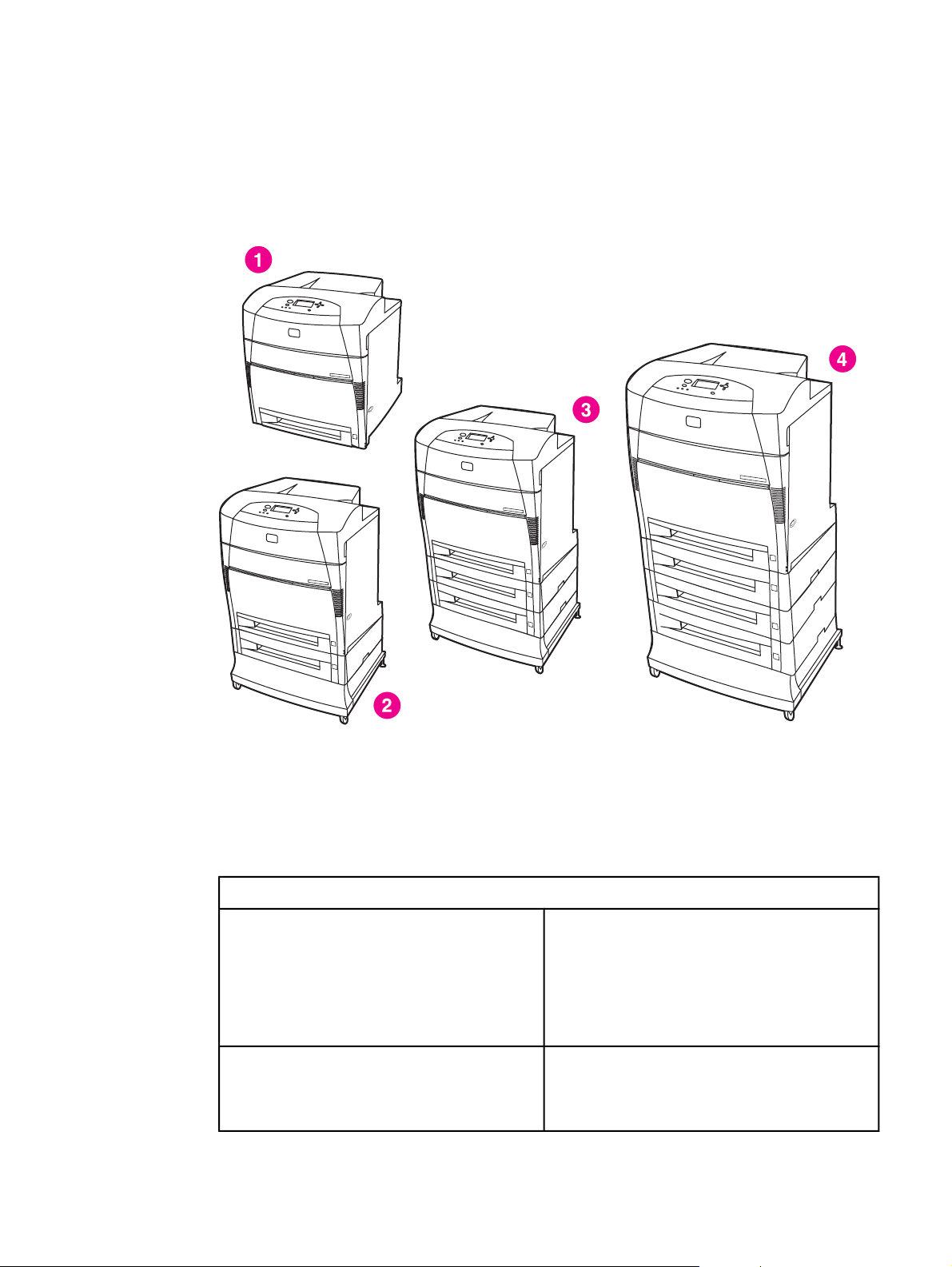
Model Configurations
This printer combines the quality and reliability of Hewlett-Packard printing with the features
listed below. For more information on printer features, see the Hewlett-Packard website at
http://www.hp.com/support/clj5500 or http://www.hp.com/support/clj5550.
The HP Color LaserJet 5500 series printer
1 HP Color LaserJet 5500, 5500n, 5550, 5550n, 5500dn, and 5550dn printers
2 HP Color LaserJet 5550dtn and 5550dtn printers
3 HP Color LaserJet 5500dtn and 5550dtn printers
4 HP Color LaserJet 5550hdn printer
Table 1-1. Model configurations
HP LaserJet 5500 models
HP Color LaserJet 5500 printer (model number
C9656A)
HP Color LaserJet 5500n printer (model number
C7131A)
The HP CLJ 5500 printer is the base model,
which includes 96 megabytes (MB) of
synchronous dynamic random access memory
(SDRAM), one 500-sheet input tray. This model
comes with three optional EIO slots, standard bidirectional parallel port (IEEE-1284-C compliant),
and a Fast InfraRed (FIR) port.
The HP CLJ 5500n printer contains all of the
features of the base model plus an HP Jetdirect
615N print server (network card) and is only
available in Europe.
2 Chapter 1 Printer description ENWW
Page 24

Table 1-1. Model configurations (continued)
HP Color LaserJet 5500dn printer (model
number C9657A)
The HP CLJ 5500dn printer contains all of the
features of the base model plus an HP Jetdirect
615N print server (network card), and automatic
2-sided printing (duplexing).
HP Color LaserJet 5500dtn printer (model
number C9658A)
HP Color LaserJet 5500hdn printer (model
number C9659A)
HP LaserJet 5550 models
HP Color LaserJet 5550 printer (model number
Q3713A)
The HP CLJ 5500dtn printer contains all of the
features of the base model plus an HP Jetdirect
615N print server (network card) and automatic 2sided printing (duplexing), an additional 500sheet feeder, and 160 MB of SDRAM.
The HP CLJ 5500hdn printer contains all of the
features of the base model with an HP Jetdirect
615N print server (network card) and automatic 2sided printing (duplexing), two additional 500sheet feeders, a hard disk, and 160 MB of
SDRAM.
The HP CLJ 5550 printer is the base model,
which includes 128 megabytes (MB) of dual-datarate (DDR) synchronous dynamic random access
memory (SDRAM), plus 32 MB of additional
memory on the formatter board for a total of 160
MB of memory, and a 500-sheet input tray.
The printer provides three enhanced input/output
(EIO) slots, wireless connectivity, an auxiliary
port, a universal serial bus (USB) connection, and
a standard bidirectional parallel cable interface
(IEEE-1284-C compliant).
HP Color LaserJet 5550n printer (model number
Q3714A)
HP Color LaserJet 5550dn printer (model
number Q3715A)
HP Color LaserJet 5550dtn printer (model
number Q3716A)
HP Color LaserJet 5550hdn printer (model
number Q3717A)
The HP CLJ 5550n printer contains all of the
features of the base model plus an HP Jetdirect
620N print server (network card).
The HP CLJ 5550dn printer contains all of the
features of the base model plus an HP Jetdirect
620n print server (network card) and automatic 2sided printing (duplexing).
The HP CLJ 5550dtn printer contains all of the
features of the base model plus an HP Jetdirect
620N print server (network card), automatic 2sided printing (duplexing), an additional 500sheet feeder.
This model has 256 MB of DDR SDRAM, plus 32
MB of additional memory on the formatter board
for a total of 288 MB of memory.
The HP CLJ 5550hdn printer contains all of the
features of the base model plus an HP Jetdirect
620N print server (network card), automatic 2sided printing (duplexing), and three addtional
500-sheet feeders.
This model has 256 MB of DDR SDRAM, plus 32
MB of additional memory on the formatter board
for a total of 288 MB of memory.
ENWW Model Configurations 3
Page 25

Performance, memory, and other printer features
This printer series combines the quality and reliability of Hewlett-Packard printers with the
features listed in
Table 1-2. Features
Table 1-2. Features.
Performance
Memory
User interface
● HP Color LaserJet 5500 models: Up to 22 pages per minute
(ppm) for A4-size paper and up to 21 ppm for letter size paper
HP Color LaserJet 5550 models: Up to 28 pages per minute
(ppm) on A4 size paper and up to 27 ppm for letter size paper
● Also prints on transparencies and glossy paper
● HP Color LaserJet 5500, 5500n, 5500dn models contain 96MB of
synchronous dynamic random access memory (SDRAM).
Memory specification: All HP Color LaserJet 5550 series printers
use 200-pin SODIMM that support 128 or 256MB of RAM
● HP Color LaserJet 5500dtn and 5500hdn printer models contain
160MB SDRAM.
● HP Color LaserJet 5550, 5550n, 5550dn models contain 160MB
DDR plus 32MB of additional memory on the formatter board and
an additional open DIMM slot.
HP Color LaserJet 5550dtn and 5550hdn models contain 288MB
of SDRAM: 256MB DDR plus 32MB of additional memory on the
formatter board and an additional DIMM slot.
These printer models contain two 200-pin SODIMM slots that
accept 128 or 256 MB RAM each
● Optional hard drive can be added via an EIO slot (included with
the HP Color LaserJet 5500hdn and 5550hdn models only). This
is optional for all other printer models.
● Graphic display on control panel
● Enhanced Help with animated graphics
● Embedded Web server to access support and order supplies
(network-connected printers)
● HP Toolbox software provides printer status and alerts, configure
printer settings, view documentation and troubleshooting
information, and print internal printer information pages (for
HP Color LaserJet 5550 models only).
Supported printer
personalities
Storage features
Fonts ● 80 internal fonts available for both PCL and PostScript emulation
● HP PCL 6
● HP PCL 5c
● PostScript 3 emulation
● Automatic language switching
● Direct PDF support (HP Color LaserJet 5550 models only)
● XHTML support (HP Color LaserJet 5550 models only)
● Job storage (for printers with a hard disk)
● Personal identification number (PIN) printing (for printers with
hard drives)
● Fonts and forms
● 80 printer-matching screen fonts in TrueType™ format available
with the software solution
● Supports forms and fonts on the hard drive using HP Web Jetadmin.
4 Chapter 1 Printer description ENWW
Page 26

Table 1-2. Features (continued)
Paper handling ● Prints on paper from 76 x 127 mm (3 x 5 inches) up to 306 x 470
mm (12.1 x 18.5 inches)
●
Prints on paper with weights from 60 g/m
bond)
● Prints on a wide range of media types including glossy, labels,
overhead transparencies, and envelopes
● Multiple gloss levels
● A 500-sheet paper feeder (Tray 2) that supports paper sizes from
148 x 210 mm (5.8 x 8.3 inches) up to 297 x 432 mm (11.6 x 17
inches).
● Optional 500-sheet paper feeders (Trays 3, 4, and 5 (HP Color
LaserJet 5550 models only) supports paper sizes from 148 x 210
mm (5.8 x 8.3 inches) up to 297 x 432 mm (11.6 x 17 inches).
● Automatic two-sided printing on all HP Color LaserJet
5500dn/5550dn, HP Color LaserJet 5500dtn/5550dtn, and
HP Color LaserJet 5500hdn/5550hdn printers
● 250-sheet face-down output bin.
2
to 199 g/m2 (16 to 53 lb
Accessories
Connectivity
● Printer hard drive, which provides storage for fonts and macros as
well as job storage; standard on HP Color LaserJet 5500hdn and
5550hdn models only
● Printer stand (recommended for additional optional trays)
● Optional Tray 3 is standard on the HP Color LaserJet 5500dtn
and HP Color LaserJet5550dtn models. Optional trays 3 and 4
are standard on the HP Color LaserJet 5500hdn models. Optional
Trays 3, 4, and 5 are standard on the HP Color LaserJet 5550hdn
models. All optional trays support support paper sizes from 148 x
210 mm (5.8 x 8.3 inches) up to 297 x 432 mm (11.6 x 17 inches).
● HP Color LaserJet 5500 models: Fast InfraRed (FIR) pod
● HP Color LaserJet 5550 models: Two-200-pin DDR SDRAM slots.
One slot is available for adding memory to the printer. DDR
SDRAM memory is available in 128 and 256 MB modules
● HP Color LaserJet 5500 supports four 168-pin dual inline memory
(DIMM) slots and the fifth 100-pin DIMM slot. Memory can be
expanded up to 416 MB, which is available in 64MB, 128MB, or
256MB.
● Optional enhanced input/output (EIO) network card; comes
standard on HP Color LaserJet 5500n/5550n, HP Color LaserJet
5500dn/5550dn, HP Color LaserJet 5550dtn/5550dtn,
andHP Color LaserJet 5500hdn/5550hdn printers
● HP Color LaserJet 5550 models only: USB 1.1 connection
● HP Web Jetadmin software
● Standard bidirectional parallel cable interface (IEEE -1284-C
compliant)
● The HP Color LaserJet 5550 model printer supports an auxiliary
connection for paper handling input devices.
● HP Color LaserJet 5550 models only: Both USB and parallel
connections are supported, but cannot be used at the same time
● HP Color LaserJet 5500 model only: Infrared (FIR) connection.
Supplies ● Supplies status page contains information on toner level, page
count, and estimated pages remaining
● No-shake cartridge design
● Printer checks for authentic HP print cartridges at cartridge
installation
● Internet-enabled supply-ordering capabilities (using embedded
Web server, printer Status and Alerts, or Toolbox (HP Color
LaserJet 5550 models only)
ENWW Performance, memory, and other printer features 5
Page 27

Identification
Model and serial numbers
The model number and serial numbers are listed on identification labels located on the rear
of the printer. The model number is alphanumeric, such as C9656A for the HP Color
LaserJet 5550. The serial number contains information about the country/region of origin,
the printer version, production code, and the production number of the printer.
Figure 1-1.
Model and serial number information
Power and regulatory information
The identification labels on the rear of the printer also contain power rating and regulatory
information as shown in
Figure 1-2. Sample label.
6 Chapter 1 Printer description ENWW
Page 28
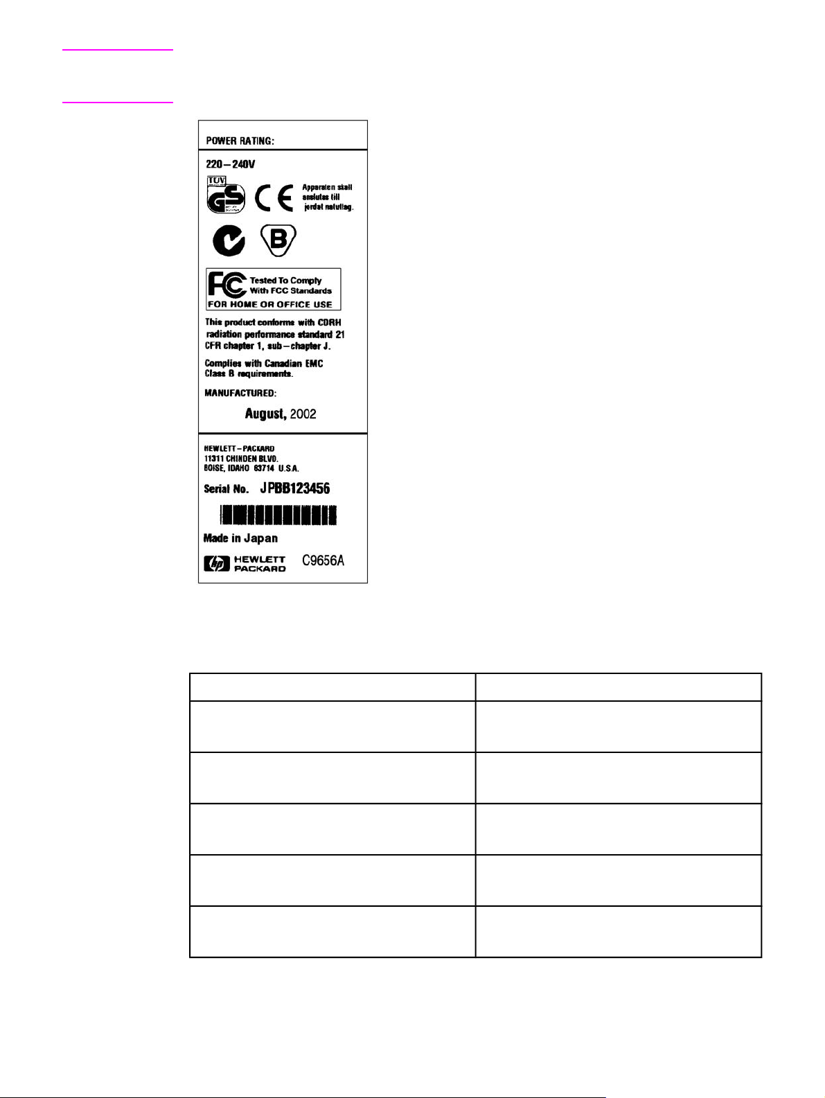
CAUTION
Converting the voltage on the printer can damage the printer. Do not use any voltage other
than the operating voltage. Any attempt to convert operating voltages will void the product
warranty (for example, attempting to change a 110V printer to a 220V printer).
Figure 1-2.
Sample label
Table 1-3. Model names and numbers
Model name Model number
HP Color LaserJet 5500
HP Color LaserJet 5550
HP Color LaserJet 5500n
HP Color LaserJet 5550n
HP Color LaserJet 5500dn
HP Color LaserJet 5550dn
HP Color LaserJet 5500dtn
HP Color LaserJet 5550dtn
HP Color LaserJet 5500hdn
HP Color LaserJet 5550hdn
C9656A
Q3713A
C7131A
Q3714A
C9657A
Q3715A
C9658A
Q3716A
C9659A
Q3717A
ENWW Identification 7
Page 29
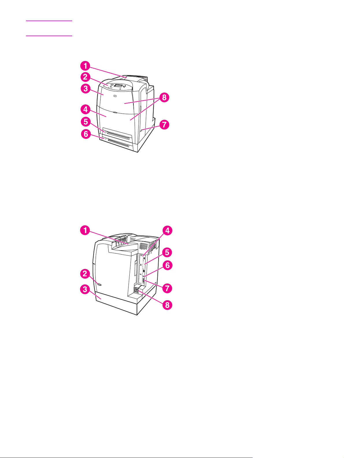
Note
This manual describes the HP Color LaserJet 5500 series printer which includes the
HP Color LaserJet 5500 models and the HP Color LaserJet 5550 models.
HP Color LaserJet 5500 models
Figure 1-3.
Figure 1-4.
Front view, HP Color LaserJet 5500 models
1 Output bin
2 Printer control panel
3 Top cover
4 Front cover (includes tray 1)
5 Tray 2 (500-sheet standard tray)
6 Tray 3 (500-sheet paper feeder; optional)
7 On/off switch
8 Access to print cartridges, transfer unit, and fuser
Back view, HP Color LaserJet 5500 models
1 Output bin
2 On/off switch
3 Tray 3 500-sheet paper feeder (optional)
4 EIO connections (3 total)
5 Memory access
6 Fast InfraRed (FIR) connection
7 Parallel connection
8 Power connection
8 Chapter 1 Printer description ENWW
Page 30
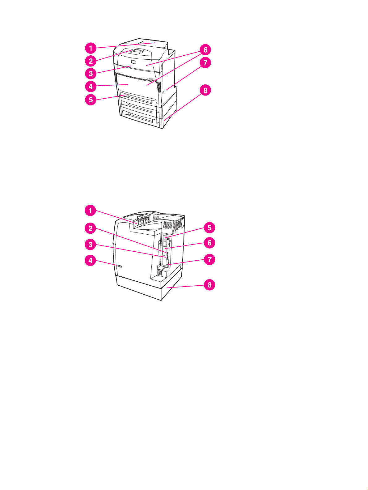
HP Color LaserJet 5550 models
Figure 1-5.
Figure 1-6.
Front view, HP Color LaserJet 5550 models
1 Output bin
2 Printer control panel
3 Top cover
4 Front cover includes Tray 1
5 Tray 2 (500 sheet standard tray)
6 Access to print cartridges, transfer unit, and fuser
7 On/off switch
8 Tray 3, Tray 4, and Tray 5 (optional)
Back view, HP Color LaserJet 5550 models
1 Output bin
2 Auxiliary connector
3 Parallel connection
4 On/off switch
5 EIO connections (3 total)
6 Memory access
7 1.1 USB connection
8 Tray 3, Tray 4, or Tray 5 (optional)
ENWW Identification 9
Page 31

Printer specifications
Table 1-4. Physical dimensions (HP Color LaserJet 5500 models) describes the dimensions
of the printer.
Maximum duty cycle is 120,000 pages per month.
Table 1-6. Acoustic emissions (HP Color LaserJet 5500 lists the acoustic emissions of the
printer when it is printing and when it is in standby mode.
Table 1-4. Physical dimensions (HP Color LaserJet 5500 models)
Product Height Depth Width Weight
HP Color
LaserJet 5500
HP Color
LaserJet 5500
with optional
Tray 3 and stand
HP Color
LaserJet 5500
with optional
Trays 3 and 4
and stand
640 mm
(25.2 in)
986 mm
(38.8 in)
1119 mm
(44 in)
704 mm
(27.7 in)
718 mm
(28.25 in)
718 mm
(28.25 in)
577 mm
(22.7 in)
630 mm
(24.8 in)
630 mm
(24.8 in)
60 kg
(132 lbs)
113 kg
(250 lbs)
128 kg
(283 lbs)
Table 1-5. Physical dimensions (HP Color LaserJet 5550 models)
Product Height Depth Width Weight
HP Color
LaserJet 5550,
5550n, and
5550dn models
HP Color
LaserJet 5550
with optional
Trays 3 and stand
640 mm
(25.2 in)
986 mm
(38.8 in)
704 mm
(27.7 in)
718 mm
(28.25 in)
577 mm
(22.7 in)
630 mm
(24.8 in)
60 kg
(132 lbs)
113 kg
(250 lbs)
HP Color
LaserJet
5550hdn models
with optional
Trays 3, 4, and 5
and stand
1237 mm
(48.7 in)
718 mm
(28.25 in)
630 mm
(24.8 in)
144 kg
(317 lbs)
Table 1-6. Acoustic emissions (HP Color LaserJet 5500
Activity level Operator (<1m) Bystander (1m) Sound power
Active
Idle
L
56 dB (A) L
pAm
L
35 dB (A)
pAm
(inaudible)
49 dB (A) L
pAm
L
33 dB (A)
pAm
(inaudible)
6.5 Bels (A)
WAd
L
4.9 Bels (A)
WAd
(inaudible)
10 Chapter 1 Printer description ENWW
Page 32

Table 1-6. Acoustic emissions (HP Color LaserJet 5500 (continued)
Activity level Operator (<1m) Bystander (1m) Sound power
Note
Powersave
L
N/A dB (A) L
pAm
N/A dB (A) L
pAm
N/A Bels (A)
WAd
These values are subject to change. See http://www.hp.com/support/lj5500 for current
information.
Table 1-7. Acoustic emissions (HP Color LaserJet 5550 models)
Sound Power Level Declared Per ISO 9296
Printing (28 PPM)
Ready
L
=6.6 Bels (A) [66 dB (A)]
WAd
=4.9 Bels (A) [49 dB (A)]
L
WAd
Sound Pressure Level - Bystander Position Declared Per ISO 9296
Printing (28 PPM)
Ready
1
Values current as of January 25, 2004. Values subject to change, see http://www.hp.com/
L
pAm
L
pAm
=49dB (A)
=33 dB (A)
support/clj5550 for current information.
2
Configuration tested: Base unit printing A4 monochrome from standard tray.
Table 1-8. The electrical specifications table lists the electrical specifications required
to run the printer safely.
Note
Item 110-volt models 220-volt models
Power supply 100 to 127 V (+/- 10 %) 220 to 240 V (+/- 10 %)
50 to 60 Hz (+/- 2 Hz) 50 to 60 Hz (+/- 2 Hz)
Power consumption (typical)
During printing 592 W (average) 562 W (average)
During standby 54 W (average) 51 W (average)
Power Save mode 48 W (average) 44 W (average)
Off mode
01 W (average)
0.15 W (average)
Heat output
Idle 181 BTU/hr 174 BTU/hr
Minimum recommended circuit
10.1 A 5 A
capacity
1
* When the printer is in standby mode, it continues to consume a minimal amount of energy.
This information is preliminary and might not be current. Please see http://www.hp.com/
support/lj5500 or http://www.hp.com/support/lj5550 for current information .
Table 1-9. Power Consumption (average in watts) (HP Color LaserJet 5550 models)
Power Consumption (average, in watts)
1
ENWW Printer specifications 11
Page 33

Table 1-9. Power Consumption (average in watts) (HP Color LaserJet 5550 models)
(continued)
Product Model
Printing (28 PPM)2Ready
4
PowerSave
(Sleep 2)
3
Off
HP Color
LaserJet 5550
HP Color
LaserJet 5550n
HP Color
LaserJet 5550dn
HP Color
LaserJet 5550dtn
HP Color
LaserJet 5550hdn
1
Values current as of February 2, 2004. Values subject to change, see http://www.hp.com/
611 W 93 W 23 W 0.3 W
614 W 93 W 24 W 0.3 W
630 W 93 W 24 W 0.3 W
630 W 93 W 24 W 0.3 W
632 W 93 W 28 W 0.3 W
support/clj5550 for current information.
2
Power reported is the highest value measured for color and monochrome printing using all
standard voltages.
3
Default time from Ready Mode to Sleep 2 = 30 minutes.
4
Heat dissipation in Ready Mode = 318 BTU/Hour.
Supply storage requirements (HP Color LaserJet 5500 series)
The life of supplies is greatly affected by their storage environment. Use to determine the
shelf life of stored supplies.
Table 1-10. Supply storage requirements
Item Storage time Storage condition
Temperature Normal (maximum of 2.5 years) 0° to 35° C (32° to 95° F)
Severe (maximum of 18 days) High 35° to 40° C (95° to 104°
F)
Low 0° to -20° C (32° to -4° F)
Maximum temperature change
rate
Humidity Normal (maximum of 2.5 years) 35% to 85% RH
Atmospheric pressure 460 to 760 mmHg (18.1 to 29.9 in Hg)
Storage time
1
1 The average storage time includes use time. Use cartridges within 2.5 years of the date
1
40° to 15° C (104° to 59° F) within 3 minutes
-20° to 25° C (-4° to 77° F) within 3 minutes
Severe (maximum of 18 days) High 85% to 95% RH
Low 10% to 35% RH
2.5 years
code on the cartridge.
12 Chapter 1 Printer description ENWW
Page 34

Product information
Product information
The specifications for the HP Color LaserJet 5500 and HP Color LaserJet 5550 are
described in this section.
Table 1-11. Printer functions
Printer function HP Color LaserJet 5500 HP Color LaserJet 5550
Print speed up to 22 pages/min in A4
landscape
up to 21.5 pages/min in letter
up to 10 pages/min in A3 and
ledger
First print time Max 18 seconds Max 16 seconds
Maximum power consumption Max 1,380W Max 1,440W
From Ready Max 18 seconds Max 16 seconds
From Cold Start Max 155 seconds Max 145 seconds
From Warm Start Max 155 seconds Max 78 seconds
From Powersave Max 45 seconds Max 45 seconds
up to 28 pages/min in A4
landscape
up to 27 pages/min in letter
up to 13 pages/min in A3 and
ledger
Electrical Specifications (HP Color LaserJet 5500 models)
Table 1-12. Electrical specifications (HP LaserJet 5500 models)
Item 110-volt models 220-volt models
Power supply 100 to 127 V (+/- 10 %) 220 to 240 V (+/- 10 %)
50 to 60 Hz (+/- 2 Hz) 50 to 60 Hz (+/- 2 Hz)
Power consumption (typical)
During printing 592 W (average) 562 W (average)
During standby 54 W (average) 51 W (average)
Power Save mode 48 W (average) 44 W (average)
Off mode
Heat output
Idle 181 BTU/hr 174 BTU/hr
Minimum recommended circuit
capacity
1
* When the printer is in standby mode, it continues to consume a minimal amount of energy.
01 W (average)
10.1 A 5 A
0.15 W (average)
ENWW Product information 13
Page 35

Electrical specifications (HP Color LaserJet 5550 models)
WARNING!
Power requirements are based on the country/region where the printer is sold. Do not
convert operating voltages. This may damage the printer and void the product warranty.
Table 1-13. Electrical specifications and requirements
110-Volt Models 230-Volt Models
Power Requirements 110-127V (+/- 10%)
50/60 Hz (+/- 2 Hz)
220-240V (+/- 10%)
50/60 Hz (+/- 2 Hz)
Rated short term current 7.0 Amps 3.0 Amps
Table 1-14. Power consumption
1
PowerSave
(Sleep 2)
3
Off
Product Model
HP Color
LaserJet 5550
HP Color
LaserJet 5550n
Power Consumption (average, in watts)
Printing (28 PPM)2Ready
4
611 W 93 W 23 W 0.3 W
614 W 93 W 24 W 0.3 W
HP Color
630 W 93 W 24 W 0.3 W
LaserJet 5550dn
HP Color
630 W 93 W 24 W 0.3 W
LaserJet 5550dtn
HP Color
632 W 93 W 28 W 0.3 W
LaserJet 5550hdn
1
Values current as of February 2, 2004. Values subject to change, see http://www.hp.com/
support/clj5500 or http://www.hp.com/support/clj5550 for current information.
2
Power reported is the highest value measured for color and monochrome printing using all
standard voltages.
3
Default time from Ready Mode to Sleep 2 = 30 minutes.
4
Heat dissipation in Ready Mode = 318 BTU/Hour.
Table 1-15. Operating environment specifications
Environment Allowed
Temperature HP Color LaserJet 5500models:15 to 27°C (59
to 81°F)
HP Color LaserJet 5550 models: (10 to 30°C)
(50 to 86°F)
Humidity HP Color LaserJet 5500 models: 10 to 70% RH
HP Color LaserJet 5550 models: 10 to 80% RH
Altitude (8530 ft, 2600 meters)
14 Chapter 1 Printer description ENWW
Page 36

Note
These values are subject to change. See http://www.hp.com/support/clj5500 or
http://www.hp.com/support/clj5550 for current information.
ENWW Product information 15
Page 37

Media requirements
Selecting print media
You can use many types of paper and other print media with this printer. This section
provides guidelines and specifications for selecting and using different print media.
Before purchasing any media or specialized forms in quantity, verify that your paper supplier
obtains and understands the print media requirements specified in the HP LaserJet Family
Print Media Guide.
It is possible that media could meet all of the guidelines in this chapter and still not print
satisfactorily. This may be a result of abnormal characteristics of the printing environment or
of other variables over which Hewlett-Packard has no control (for example, extremes in
temperature and humidity).
Hewlett-Packard recommends testing any media before buying it in large quantities.
CAUTION
Using media that does not conform to the specifications listed here and in the HP LaserJet
Family Print Media Specification Guide can cause problems that require service. This
service is not covered by the Hewlett-Packard warranty or service agreements.
Media specifications
For optimum results, use conventional 75 g/m2 (20 lb) xerographic paper. Verify that the
paper is of good quality and is free of cuts, nicks, tears, spots, loose particles, dust, wrinkles,
curls, or bent edges. Avoid fanning the print media before loading it into the paper trays.
Supported media weights and sizes (HP Color LaserJet 5500 models)
Table 1-16. Tray 1 (multi-purpose tray) supported media specifications and Table 1-17. Tray
2, Tray 3, and Tray 4 supported media specifications show the media types and sizes
supported by the printer and the printer accessories.
Table 1-16. Tray 1 (multi-purpose tray) supported media specifications
Media type Dimensions Weight or thickness Capacity
Standard size paper/
cardstock (Letter/A4,
Legal, Executive, JIS
B5, B5-R, A5, A5-R,
1
11 x 17
, A3)
60 to 200 g/m
(16 to 53 lb bond)
2
100 sheets
(75 g/m
2
; 20 lb bond)
Minimum size paper/
cardstock
Maximum size paper/
cardstock
76 by 127 mm
(3 by 5 in)
312 by 470 mm
(12.3 by 18.5 in)
60 to 200 g/m
(16 to 53 lb bond)
60 to 200 g/m
(16 to 53 lb bond)
2
2
100 sheets
(75 g/m
100 sheets
(75 g/m
2
; 20 lb bond)
2
; 20 lb bond)
16 Chapter 1 Printer description ENWW
Page 38

Table 1-16. Tray 1 (multi-purpose tray) supported media specifications (continued)
Media type Dimensions Weight or thickness Capacity
Standard size glossy
paper (Letter/A4,
Letter-R, A4-R, Legal,
Executive, JIS B5, B5R, A5, A5-R, 11 x 17,
A3)
Minimum size glossy
paper
Maximum size glossy
paper
Standard size
transparencies (Letter/
A4, Letter-R, A4-R,
Legal, Executive, JIS
B5, B5-R, A5, A5-R,
11 x 17, A3)
Minimum size
transparencies
Maximum size
transparencies
Standard size tough
paper (Letter/A4,
Letter-R, A4-R, Legal,
Executive, JIS B5, B5R, A5, A5-R, 11 x 17,
A3)
76 by 127 mm
(3 by 5 in)
312 by 470 mm
(12.3 by 18.5 in)
76 by 127 mm
(3 by 5 in)
312 by 470 mm
(12.3 by 18.5 in)
75 to 163 g/m
2
(20 to 43 lb bond)
75 to 163 g/m
2
(20 to 43 lb bond)
75 to 163 g/m
2
(20 to 43 lb bond)
0.12 to 0.13 mm thick
(4.7 to 5.5 mils thick)
0.12 to 0.13 mm thick
(4.7 to 5.5 mils thick)
0.12 to 0.13 mm thick
(4.7 to 5.5 mils thick)
0.10 to 0.13 mm thick
(4 to 5.5 mils thick)
Maximum stack
height: 10 mm (0.4 in)
Maximum stack
height: 10 mm (0.4 in)
Maximum stack
height: 10 mm (0.4 in)
Maximum stack
height: 10 mm (0.4 in)
Maximum stack
height: 10 mm (0.4 in)
Maximum stack
height: 10 mm (0.4 in)
Maximum stack
height: 10 mm (0.4 in)
Minimum size tough
paper
Maximum size tough
paper
Envelope (Com 10,
Monarch, C5, DL, B5)
76 by 127 mm
(3 by 5 in)
312 by 470 mm
(12.3 by 18.5 in)
0.10 to 0.13 mm thick
(4 to 5.5 mils thick)
0.10 to 0.13 mm thick
(4 to 5.5 mils thick)
75 to 105 g/m
(20 to 28 lb bond)
Standard size label
(Letter/A4, Letter-R,
A4-R, Legal,
Executive, JIS B5, B5R, A5, A5-R, 11 x 17,
A3)
Minimum size label 76 by 127 mm
(3 by 5 in)
Maximum size label 312 by 470 mm
(12.3 by 18.5 in)
1
11 x 17 inch, Ledger, and Tabloid sizes are all the same.
Maximum stack
height: 10 mm (0.4 in)
Maximum stack
height: 10 mm (0.4 in)
2
20 sheets
(10 mils thick
Maximum stack
height: 10 mm (0.4 in)
Maximum stack
height: 10 mm (0.4 in)
Maximum stack
height: 10 mm (0.4 in)
ENWW Media requirements 17
Page 39

Table 1-17. Tray 2, Tray 3, and Tray 4 supported media specifications
Media type Dimensions Weight or thickness Capacity
Standard size paper
(Letter/A4, Letter-R,
A4-R, Legal,
Executive, JIS B5
1
, B5R, A5, A5-R, 11 by 17,
A3)
Minimum size paper 148 by 210 mm
(5.8 by 8.3 in)
Maximum size paper/
cardstock
297 by 432 mm
(11.7 by 17 in)
Standard size glossy
paper (Letter/A4,
Letter-R, A4-R, Legal,
Executive, JIS B5, B5R, A5, A5-R, 11 x 17,
A3)
Minimum size glossy
paper
Maximum size glossy
paper
148 by 210 mm
(5.8 by 8.3 in)
297 by 432 mm
(11.7 by 17 in)
Standard size
transparencies (Letter/
A4, Letter-R, A4-R,
Legal, Executive, JIS
B5, B5-R, A5, A5-R,
11 x 17, A3)
60 to 163 g/m
2
(16 to 43 lb bond)
60 to 163 g/m
2
(16 to 43 lb bond)
60 to 163 g/m
2
(16 to 43 lb bond)
75 to 163 g/m
2
(20 to 43 lb bond)
60 to 163 g/m
2
(16 to 43 lb bond)
60 to 163 g/m
2
(16 to 43 lb bond)
0.12 to 0.13 mm thick
(4.7 to 5.5 mils thick)
500 sheets
(75 g/m
2
; 20 lb bond)
500 sheets
(75 g/m
2
; 20 lb bond)
100 sheets
(75 g/m
2
; 20 lb bond)
200 sheets
200 sheets
200 sheets
100 sheets
(0.13 mm thick;
5.5 mils thick)
Minimum size
transparencies
Maximum size
transparencies
Standard size Tough
paper (Letter/A4,
Letter-R, A4-R, Legal,
Executive, JIS B5, B5R, A5, A5-R, 11 by 17,
A3)
Minimum size Tough
paper
Maximum size Tough
paper
148 by 210 mm
(5.8 by 8.3 in)
297 by 432 mm
(11.7 by 17 in)
148 by 210 mm
(5.8 by 8.3 in)
297 by 432 mm
(11.7 by 17 in)
0.12 to 0.13 mm thick
(4.7 to 5.5 mils thick)
0.12 to 0.13 mm thick
(4.7 to 5.5 mils thick)
0.10 to 0.13 mm thick
(4 to 5.5 mils thick)
0.10 to 0.13 mm thick
(4 to 5.5 mils thick)
0.10 to 0.13 mm thick
(4 to 5.5 mils thick)
100 sheets
(0.13 mm thick;
5.5 mils thick)
100 sheets
(0.13 mm thick;
5.5 mils thick)
100 sheets
(0.13 mm thick;
5.5 mils thick)
100 sheets
(0.13 mm thick;
5.5 mils thick)
100 sheets
(0.13 mm thick;
5.5 mils thick)
18 Chapter 1 Printer description ENWW
Page 40

Table 1-17. Tray 2, Tray 3, and Tray 4 supported media specifications (continued)
Media type Dimensions Weight or thickness Capacity
Standard size label
(Letter/A4, Letter-R,
A4-R, Legal,
Executive, JIS B5, B5R, A5, A5-R, 11 x 17,
A3)
Minimum size label 148 by 210 mm
(5.8 by 8.3 in)
Maximum size label 297 by 432 mm
(11.7 by 17 in)
1
Trays 2, 3, and 4 use “Custom” size specifically for B5 ISO. Trays 2, 3, and 4 do not
Maximum stack
height: 50 mm (2 in)
Maximum stack
height: 10 mm (0.4 in)
Maximum stack
height: 10 mm (0.4 in)
support the range of custom sizes available in Tray 1.
Supported paper weights and sizes (HP Color LaserJet 5550 models)
Letter and A4 sizes can be loaded with the long-edge or short-edge leading into the printer.
Long-edge first is the preferred orientation. Long-edge feed gives greater throughput, and
lower consumable usage. Short-edge feed is called the rotated orientation, and is identified
in the trays as LTR-R and A4-R. Short-edge feed can be useful when printing on media with
special features, such as perforations or windows.
Table 1-18. Tray 1 paper sizes and types
Tray 1 Dimensions Weight or thickness Capacity
Minimum size (unless
otherwise noted)
Maximum size (unless
otherwise noted)
Nondetectable
standard sizes: Letter,
Letter-Rotated, A4, A4Rotated, Legal,
Executive, A5, A3,
RA3, 11 x 17, B4(JIS),
B5(JIS), Double post
card(JIS), 16K, 8K,
Executive (JIS), 12 x
18, 8.5 x 13, A6, JISB6, Statement, #10
envelope, DL
Envelope, C5
Envelope, B5
Envelope, Monarch
Envelope. (Tray 1 has
no automatically
detectable standard
sizes.)
1
76 by 127 mm
(3 by 5 in)
306 by 470 mm
(12.1 by 18.5 in)
(16 to 53 for all
models lb bond)
Plain paper
75 to 89 g/m
(20 to 23 lb bond)
2
100 sheets
(75 g/m
2
; 20 lb bond)
ENWW Media requirements 19
Page 41

Table 1-18. Tray 1 paper sizes and types (continued)
Tray 1 Dimensions Weight or thickness Capacity
Light paper
60 to 74 g/m
2
(16 to 19 lb bond)
Intermediate paper
90 to 104 g/m
2
(24 to 27 lb bond)
Heavy paper
105 to 119 g/m
2
(28 to 31 lb bond)
Extra heavy paper
120 to 164 g/m
2
(32 to 43 lb bond)
Cardstock
163 to 200 g/m
2
(44 to 53 lb bond)
Glossy paper
75 to 105 g/m
2
(20 to 28 lb bond)
Heavy Glossy
106 to 120 g/m
2
(29 to 32 lb bond)
High Gloss Images
120 to 120 g/m
2
(32 to 32 lb bond)
Transparency 0.12 to 0.13 mm thick
(4.7 to 5.5 mils thick)
Tough Paper 0.10 to 0.13 mm thick
(4 to 5 mils thick)
100 sheets
Maximum stack
height: 10 mm (0.4 in)
Maximum stack
height: 10 mm (0.4 in)
Maximum stack
height: 10 mm (0.4 in)
Maximum stack
height: 10 mm (0.4 in)
Maximum stack
height: 10 mm (0.4 in)
Maximum stack
height: 10 mm (0.4 in)
Maximum stack
height: 10 mm (0.4 in)
Maximum stack
height: 10 mm (0.4 in)
Maximum stack
height: 10 mm (0.4 in)
Note
Envelopes
75 to 105 g/m
2
20 envelopes
(20 to 28 lb bond)
Labels Maximum stack
height: 10 mm (0.4 in)
1
Paper up to 312 mm wide can be fed through the paper path, but most drivers only support
306 mm maximum width.
The following table lists the standard sizes of paper that the printer can automatically detect
when loaded in Tray 2 and optional Trays 3, 4, and 5.
20 Chapter 1 Printer description ENWW
Page 42

Table 1-19. Tray 2 and optional Trays 3, 4, and 5 (5550 model only) paper sizes and
types
Tray 2 and optional
Trays 3, 4, and 5
(5550 model only)
Automatically
detectable standard
sizes: Letter, LetterRotated, A4, A4Rotated, A3, 11x17,
Legal, B4 (JIS), B5
(JIS), A5, Executive.
Trays 3 and 4 are
optional on the HP
Color LaserJet 5500
models. Trays 3, 4,
and 5 are optional on
the HP Color LaserJet
5550 models.
Nondetectable
standard sizes: 16K,
8K, Executive (JIS),
8.5 x 13
Dimensions Weight or thickness Capacity
Minimum Size (unless
otherwise noted)
Maximum size (unless
otherwise noted)
Plain paper
Light paper
76 by 127 mm
(3 by 5 in)
297 by 431 mm
(11.69 by 17 in)
75 to 89 g/m
2
(20 to 23 lb bond)
60 to 74 g/m
2
500 sheets
(75 g/m
2
; 20 g/m)
500 sheets
(16 to 19 lb bond)
Intermediate paper
Heavy paper
Extra heavy paper
Glossy paper
90 to 104 g/m
(24 to 27 lb bond)
105 to 119 g/m
(28 to 31 lb bond)
1
120 to 163 g/m
(32 to 43 lb bond)
75 to 105 g/m
2
Maximum stack
height: 50 mm (2.0 in)
2
Maximum stack
height: 50 mm (2.0 in)
2
Maximum stack
height: 50 mm (2.0 in)
2
200 sheets
(20 to 28 lb bond)
High Gloss Images
120 to 120 g/m
(32 to 32 lb bond)
2
Maximum stack
height: 10 mm (0.4 in)
Labels Maximum stack
height: 50 mm (2 in)
Transparency 0.12 to 0.13 mm thick
100 sheets
(4.7 to 5.5 mils thick)
Tough paper 0.10 to 0.13 mm thick
100 sheets
(4 to 5 mils thick)
1
The use of Extra heavy paper from Trays 2, 3, 4, and 5 is allowed, but the performance
cannot be guaranteed due to the wide variation in these papers.
ENWW Media requirements 21
Page 43

Table 1-20. Automatic two-sided printing (duplexing)
1
Automatic two-sided
printing
Standard size paper,
Letter, Letter-Rotated,
A4, A4-Rotated, Legal,
Executive, A3, 11x17,
B4 (JIS), B5 (JIS)
1
The printer automatically prints on paper weights up to 163 g/m2. However, automatic two-
Dimensions Weight or thickness Capacity
60 to 120 g/m
(16 to 32 lb bond)
2
sided printing on weights above the maximum value noted in this table can produce
unexpected results.
Manual two-sided (duplex) printing. Any of the supported paper sizes listed for printing
from Tray 1 can be manually duplexed.
Media specifications for 2-sided (duplex) printing
For automatic 2-sided printing, you can use any of the following standard-size paper in
weights from 60 to 120 g/m
● Letter/A4
● A3
● Legal
● Executive
2
(16 to 32 lb bond):
Note
Note
● JIS B5
● B4
● 11 x 17 inch
The printer automatically prints on paper weights up to 163 g/m2. However, automatic 2sided printing on weights above the maximum value noted above can produce unexpected
results.
Automatic 2-sided printing does not support rotated (short-edge first) orientation.
For manual 2-sided printing, you can use any of the supported paper sizes listed for printing
from Tray 1.
Media to avoid
This printer can handle many types of media. Using media outside the printer’s
specifications will cause a loss of print quality and increase the chance of paper jams
occurring.
● Do not use paper that is too rough.
●
Do not use paper with cutouts or perforations other than standard 3-hole punched paper.
●
Do not use multipart forms.
● Do not use paper that has already been printed on or fed through a photocopier or printer.
● Do not use paper with a watermark if you are printing solid patterns.
● Do not use paper that is embossed.
22 Chapter 1 Printer description ENWW
Page 44

Media that may cause damage to the printer
In rare circumstances media can damage the printer. To prevent possible damage, do not
use the following media:
● Do not use paper that is coated unless it is specifically recommended for use in this
printer.
● Do not use paper with staples.
● Do not use paper with irregularities such as tabs or cuts.
● Do not use preprinted forms or letterhead paper with low temperature dyes or
thermography. Preprinted forms or letterhead must use inks that can tolerate
temperatures of 190°C (374°F) for 0.1 second.
● Do not use any media that produces hazardous emissions, or that melts, offsets, or
discolors when exposed to 190°C (374°F) for 0.1 second.
● Do not use transparencies designed for use with Inkjet printers or other low temperature
printers. Use only transparencies that are specified for use with HP Color LaserJet
printers.
Printing on special media
Use these guidelines when printing on special types of media.
●
For optimum results, use conventional 75 g/m
2
(20 lb) xerographic paper.
CAUTION
● Verify that the paper is of good quality and free of cuts, nicks, tears, spots, loose
particles, dust, wrinkles, curls, or bent edges.
Transparencies
When printing on transparencies, use the following guidelines.
● Handle transparencies using the edges. Oils from your fingers can remain on the
transparency and can cause print quality problems.
● Use only overhead transparencies recommended for use in this printer. Hewlett-Packard
recommends using HP Color LaserJet transparencies with this printer. HP products are
designed to work together for optimum printing results.
● In either the software application or the driver, select Transparency as the media type.
Or, print from a tray that is configured for transparencies.
● Transparencies are not supported from Tray 5 in the HP LaserJet 5550 model.
Transparencies not designed for LaserJet printing will melt in the printer, causing damage to
the printer.
Printing on transparencies
Table 1-21. Printing on transparencies
Description Specifications
Electrical surface resistivity
ENWW Media requirements 23
2 to 15 x 10**10 ohms per square inch
Page 45

Table 1-21. Printing on transparencies (continued)
Description Specifications
Note
Fusing compatibility
Caliper (thickness)
Materials must not discolor, melt, offset, or
release hazardous emissions when heated to
190°C ( (374°F)) for 0.1 second.
0.12 mm (0.0048 in) to 0.13 mm (0.0052 in)
Glossy paper
● In either the software application or the driver, select Glossy or Heavy Glossy as the
media type, or print from a tray that is configured for glossy paper.
Select Glossy for media weights up to 105 g/m
media weights of 105 g/m
2
(28 lb bond) and heavier.
2
(28 lb bond). Select Heavy Glossy for
● Use the control panel to set the media type to GLOSSY or HEAVY GLOSSY for the
input tray being used.
Hewlett-Packard recommends using HP Color LaserJet Soft Gloss paper with this printer.
HP products are designed to work together for optimum printing results. If HP Color LaserJet
Soft Gloss paper is not used with this printer, print quality may be compromised.
Colored paper
● Colored paper should be of the same high quality as white xerographic paper.
● Pigments used must be able to withstand the printer’s fusing temperature of 190° C
(374° F) for 0.1 second without deterioration.
● Do not use paper with a colored coating that was added after the paper was produced.
● The printer creates colors by printing patterns of dots, overlaying and varying their
spacing to produce various colors. Varying the shade or color of your paper will affect
the shades of your printed colors.
Heavy paper
Table 1-22. Paper specifications
Paper type Paper weight
Heavy
Extra heavy
Cardstock
●
Any of the trays will print most heavy media that does not exceed 163 g/m
● For optimum results when printing on heavy paper, use the printer control panel to set
the media type for the tray to HEAVY (106 g/m
●
Use card stock only in Tray 1 (163 g/m
105-119 g/m2 (28-31 lb)
120-163 g/m2 (32-43 lb)
163-200 g/m2 (44-53 lb)
2
to 163 g/m2).
2
to 200 g/m2).
2
(47 lb bond).
24 Chapter 1 Printer description ENWW
Page 46

● In either the software application or the driver, select Heavy or Cardstock as the media
type, or print from a tray that is configured for heavy paper.
● Because this setting affects all print jobs, it is important to return the printer to its original
settings once your job has printed. See the section in the online user guide on
configuring input trays.
CAUTION
In general, do not use paper that is heavier than the recommended specification for this
printer. Doing so can cause misfeeds, jams, inferior print quality, and excessive mechanical
wear. However, some heavier media types, such as HP Cover Stock, can be safely used.
See
Table 1-16. Tray 1 (multi-purpose tray) supported media specifications for supported
paper types and sizes.
Printing images (HP Color LaserJet 5550 models)
To obtain the best print quality when printing images, use HP High Gloss Laser Paper
(Q2419A). In either the software program or the driver, select HIGH GLOSS or print from a
tray that is configured for glossy paper.
● In either the software program or the printer driver, select HIGH GLOSS (IMAGES) as
the media type, or print from a tray that is configured for glossy paper.
● You can also configure the printer by using settings on the printer control panel.
Envelopes
Envelopes can be printed only from Tray 1. Set the tray’s media size to the specific envelope
size. For information about loading envelopes, see the section in the online user guide about
loading envelopes into Tray 1.
Adhering to the following guidelines will help ensure proper printing on envelopes and help
prevent printer jams:
Note
CAUTION
Note
● Do not load more than 20 envelopes into Tray 1.
●
The weight rating of envelopes should not exceed 105 g/m
● Envelopes should be flat.
● Do not use envelopes with windows or clasps.
● Envelopes must not be wrinkled, nicked, or otherwise damaged.
● Envelopes with peel-off adhesive strips must use adhesives that can withstand the heat
and pressures of the printer’s fusing process.
● Envelopes should be loaded face-down and with the top of the envelope to the left, and
the short edge feeding into the printer first.
In high humidity environments, envelopes should be printed long-edge first to prevent them
from sealing during printing. For long-edge printing, envelopes should be loaded long-edge
first, face-down. See the section in the online user guide about loading envelopes in Tray 1.
To prevent severe printer damage, do not use envelopes that have windows, clasps, snaps,
or synthetic materials.
2
(28 lb).
Labels
To print labels, set the tray’s media type to LABELS in the printer control panel.
ENWW Media requirements 25
Page 47

When printing labels, use the following guidelines:
● Verify that the label’s adhesive material can tolerate temperatures of 190°C (374°F) for
0.1 second.
● Verify that adhesive material is not exposed between the labels. Exposed areas can
cause labels to peel off during printing, which can cause printer jams. Exposed adhesive
can also cause damage to printer components.
● Do not re-feed a sheet of labels.
● Verify that labels lie flat.
● Do not use labels that are wrinkled, bubbled, or otherwise damaged.
HP LaserJet Tough paper
When printing on HP LaserJet Tough paper, use the following guidelines:
● Handle HP LaserJet Tough paper using the edges. Oils from your fingers deposited on
HP LaserJet Tough paper can cause print quality problems.
● Use only Hewlett-Packard LaserJet Tough paper with this printer. HP products are
designed to work together for optimum printing results.
● In either the software application or the driver, select Tough Paper as the media type, or
print from a tray that is configured for HP LaserJet Tough paper.
Preprinted forms and letterhead
Observe the following guidelines for best results with preprinted forms and letterhead:
● Forms and letterhead must be printed with heat-resistant inks that will not melt, vaporize,
or release hazardous emissions when subjected to the printer’s fusing temperature of
approximately 190°C ( 374°F) for 0.1 second.
● Inks must be non-flammable and should not adversely affect any printer rollers.
● Forms and letterhead should be sealed in a moisture-proof wrapping to prevent changes
during storage.
● To load preprinted forms and letterhead into Tray 1, load them face down with the top
edge of the page to the left.
● Before you load preprinted paper such as forms and letterhead, verify that the ink on the
paper is dry. During the fusing process, wet ink can come off of preprinted paper.
● When simplex printing, load pre-printed forms and letterhead into trays 2, 3, 4, and 5
(HP Color LaserJet 5550 models) face-up with the top edge of the page to the left. To
load pre-printed forms and letterhead into Tray 1, load them face-down with the top edge
of the page to the left.
● When duplex printing, load preprinted forms and letterhead into Trays 2, 3, 4, and 5
(Tray 5 HP Color LaserJet 5550 models) face-down with the top edge of the page to the
left. Load preprinted forms and letterhead into Tray 1 face-up with the top edge of the
page to the left.
Recycled paper
This printer supports the use of recycled paper. Recycled paper must meet the same
specifications as standard paper; refer to the HP LaserJet Printer Family Print Media Guide,
available through HP Direct. See the online user guide for ordering information. HewlettPackard recommends that recycled paper contain no more than 5% groundwood.
26 Chapter 1 Printer description ENWW
Page 48

Weight equivalence table
Table 1-23. Weight equivalence table shows equivalent weights for different grades of
paper. A boldface type value indicates a commonly available standard weight for that grade.
Note
Text and book grades marked with an asterisk (*) actually calculate to 51, 61, 71, and 81 but
are rounded to standard book or text weights of 50, 60, 70, and 80.
Table 1-23. Weight equivalence table
Bond
weight
(17 x
22 inches)
16# 41# 22# 27# 33# 37#
17# 43# 24# 29# 35# 39#
20# 50# * 28# 34# 42# 46#
21# 54# 30# 36# 44# 49#
24# 60# * 33# 41# 50# 55#
27# 68# 37# 45# 55# 61#
28# 70# * 39# 49# 58# 65# 105 g/m2
29# 74# 41# 50# 61# 68#
Text/Book
weight
(25 x
38 inches)
Cover
weight
(20 x
26 inches)
Bristol
weight
(22.5 x
28.5 inches
)
Index
weight
(25.5 x
30.5 inches
)
Tag weight
(24 x 36
inches)
Metric
weight
60 g/m
64 g/m
75 g/m
80 g/m
90 g/m
100 g/m
110 g/m
2
2
2
2
2
2
2
32# 80# * 44# 55# 67# 74#
36# 90# 50# 62# 75# 83#
120 g/m
135 g/m
39# 100# 55# 67# 82# 91# 148 g/m2
40# 101# 55# 68# 83# 92#
150 g/m
43# 110# 60# 74# 90# 100# 163 g/m2
45# 115# 63# 77# 94# 104#
170 g/m
47# 119# 65# 80# 97# 108# 176 g/m2
51# 128# 70# 86# 105# 117#
190 g/m
53# 134# 74# 90# 110# 122# 199 g/m2
54# 137# 75# 93# 113# 125# 203 g/m2
58# 146# 80# 98# 120# 133# 216 g/m2
65# 165# 90# 111# 135# 150# 244 g/m2
66# 169# 92# 114# 138# 154#
250 g/m
67# 171# 94# 115# 140# 155# 253 g/m2
70# 178# 98# 120# 146# 162# 264 g/m2
2
2
2
2
2
2
72# 183# 100# 123# 150# 166# 271 g/m2
ENWW Media requirements 27
Page 49

Hewlett-Packard warranty statement
HP PRODUCT
HP Color LaserJet 5500/5550, 5500n/5550n,
5500dn/5550dn, 5500dtn/5550dtn, and
5500hdn/5550hdn printers
HP warrants to you, the end-user customer, that HP hardware and accessories will be free from defects in
materials and workmanship after the date of purchase, for the period specified above. If HP receives notice of
such defects during the warranty period, HP will, at its option, either repair or replace products which prove to be
defective. Replacement products may be either new or equivalent in performance to new.
HP warrants to you that HP software will not fail to execute its programming instructions after the date of
purchase, for the period specified above, due to defects in material and workmanship when properly installed and
used. If HP receives notice of such defects during the warranty period, HP will replace software which does not
execute its programming instructions due to such defects.
HP does not warrant that the operation of HP products will be uninterrupted or error free. If HP is unable, within a
reasonable time, to repair or replace any product to a condition as warranted, you will be entitled to a refund of
the purchase price upon prompt return of the product.
HP products may contain remanufactured parts equivalent to new in performance or may have been subject to
incidental use.
The warranty period begins on the date of delivery or on the date of installation if installed by HP. If customer
schedules or delays HP installation more than 30 days after delivery, warranty begins on the 31st day from
delivery.
Warranty does not apply to defects resulting from (a) improper or inadequate maintenance or calibration, (b)
software, interfacing, parts or supplies not supplied by HP, (c) unauthorized modification or misuse, (d) operation
outside of the published environmental specifications for the product, or (e) improper site preparation or
maintenance. TO THE EXTENT ALLOWED BY LOCAL LAW, THE ABOVE WARRANTIES ARE EXCLUSIVE
AND NO OTHER WARRANTY OR CONDITION, WHETHER WRITTEN OR ORAL, IS EXPRESSED OR
IMPLIED AND HP SPECIFICALLY DISCLAIMS ANY IMPLIED WARRANTIES OR CONDITIONS OF
MERCHANTABILITY, SATISFACTORY QUALITY, AND FITNESS FOR A PARTICULAR PURPOSE. Some
countries/regions, states or provinces do not allow limitations on the duration of an implied warranty, so the above
limitation or exclusion might not apply to you. This warranty gives you specific legal rights and you might also
have other rights that vary from country/region to country/region, state to state, or province to province.
HP™s limited warranty is valid in any country/region or locality where HP has a support presence for this product
and where HP has marketed this product. The level of warranty service you receive may vary according to local
standards. HP will not alter form, fit or function of the product to make it operate in a country/region for which it
was never intended to function for legal or regulatory reasons.
HP will be liable for damage to tangible property per incident up to the greater of $300,000 or the actual amount
paid for the product that is the subject of the claim, and for damages for bodily injury or death, to the extent that
all such damages are determined by a court of competent jurisdiction to have been directly caused by a defective
HP product. TO THE EXTENT ALLOWED BY LOCAL LAW, THE REMEDIES IN THIS WARRANTY
STATEMENT ARE YOUR SOLE AND EXCLUSIVE REMEDIES. EXCEPT AS INDICATED ABOVE, IN NO
EVENT WILL HP OR ITS SUPPLIERS BE LIABLE FOR LOSS OF DATA OR FOR DIRECT, SPECIAL,
INCIDENTAL, CONSEQUENTIAL (INCLUDING LOST PROFIT OR DATA), OR OTHER DAMAGE, WHETHER
BASED IN CONTRACT, TORT, OR OTHERWISE. Some countries/regions, states or provinces do not allow the
exclusion or limitation of incidental or consequential damages, so the above limitation or exclusion may not apply
to you.
THE WARRANTY TERMS CONTAINED IN THIS STATEMENT, EXCEPT TO THE EXTENT LAWFULLY
PERMITTED, DO NOT EXCLUDE, RESTRICT OR MODIFY AND ARE IN ADDITION TO THE MANDATORY
STATUTORY RIGHTS APPLICABLE TO THE SALE OF THIS PRODUCT TO YOU.
DURATION OF LIMITED WARRANTY
1 year limited warranty
28 Chapter 1 Printer description ENWW
Page 50

Limited warranty for print cartridge life
This HP product is warranted to be free from defects in materials and workmanship during its
useful life (end of life is indicated by a printer control panel low-life message).
This warranty does not cover products that have been modified, refurbished,
remanufactured, misused, or tampered with in any way.
This limited warranty gives you specific legal rights. You may have other rights which vary
from state to state, province to province, and country/region to country/region.
THE ABOVE WARRANTIES ARE EXCLUSIVE AND NO OTHER WARRANTY, WHETHER
WRITTEN OR ORAL, IS EXPRESSED OR IMPLIED. THE HEWLETT-PACKARD
COMPANY SPECIFICALLY DISCLAIMS THE IMPLIED WARRANTIES OR
MERCHANTABILITY AND FITNESS FOR A PARTICULAR PURPOSE. TO THE EXTENT
ALLOWED BY APPLICABLE LAW, IN NO EVENT SHALL HEWLETT-PACKARD
COMPANY BE LIABLE FOR ANY INCIDENTAL, CONSEQUENTIAL, SPECIAL, INDIRECT,
PUNITIVE, OR EXEMPLARY DAMAGES OR LOST PROFITS FROM ANY BREACH OF
THIS WARRANTY OR OTHERWISE.
In the event that your product proves to be defective, please return to place of purchase with
a written description of the problem.
ENWW Limited warranty for print cartridge life 29
Page 51

Transfer unit and fuser warranty
This HP product is warranted to be free from defects in materials and workmanship for one
year or until the printer control panel indicates a low-life message, whichever occurs first.
This warranty does not cover products that have been modified, refurbished,
remanufactured, misused, or tampered with in any way.
This limited warranty gives you specific legal rights. You may have other rights which vary
from state to state, province to province, and country/region to country/region.
THE ABOVE WARRANTIES ARE EXCLUSIVE AND NO OTHER WARRANTY, WHETHER
WRITTEN OR ORAL, IS EXPRESSED OR IMPLIED. THE HEWLETT-PACKARD
COMPANY SPECIFICALLY DISCLAIMS THE IMPLIED WARRANTIES OR
MERCHANTABILITY AND FITNESS FOR A PARTICULAR PURPOSE. TO THE EXTENT
ALLOWED BY APPLICABLE LAW, IN NO EVENT SHALL HEWLETT-PACKARD
COMPANY BE LIABLE FOR ANY INCIDENTAL, CONSEQUENTIAL, SPECIAL, INDIRECT,
PUNITIVE, OR EXEMPLARY DAMAGES OR LOST PROFITS FROM ANY BREACH OF
THIS WARRANTY OR OTHERWISE.
In the event that your product proves to be defective, please return to place of purchase with
a written description of the problem.
30 Chapter 1 Printer description ENWW
Page 52

Declaration of Conformity
Declaration of Conformity
according to ISO/IEC Guide 22 and EN 45014
Manufacturer’s Name: Hewlett-Packard Company
Manufacturer’s Address: 11311 Chinden Boulevard
declares that the product
Product Name: HP Color LaserJet 5500 series
Regulatory Model Number: BOISB-0202-00
Product Options: All
conforms to the following Product Specifications:
Safety: IEC 60950:1991+A1 +A2 +A3 +A4 / EN60950:1992+A1 +A2 +A3 +A4 +A11
IEC 60825-1:1993 + A1 / EN 60825-1 + A11 Class 1 Laser/LED Product
GB4943-1995
EMC:
Supplementary Information:
The product herewith complies with the requirements of the EMC Directive 89/336/EEC and the Low Voltage Directive 73/23/EEC, and carries
the CE-Marking accordingly:
1) The product was tested in a typical configuration with Hewlett-Packard Personal Computer Systems.
2) This Device complies with Part 15 of the FCC Rules. Operation is subject to the following two Conditions: (1) this device may not cause
harmful interference, and (2) this device must accept any interference received, including interference that may cause undesired operation.
*) This product includes LAN (Local Area Network) options. When the interface cable is attached to LAN connectors, the product meets the
requirements of EN55022 Class A in which case the following applies: “Warning” This is a Class A product. In a domestic environment this
product may cause radio interference in which case the user may be required to take adequate measures”.
For regulatory topics only:
Australia Contact
European Contact Your Local Hewlett-Packard Sales and Service Office or Hewlett-Packard Gmbh, Department HQ-TRE / Standards
USA Contact
CISPR 22:1993 + A1 + A2 / EN 55022:1994 + A1 + A2 Class B
EN 61000-3-2:1995 / A14
EN 61000-3-3:1995
EN 55024:1998
FCC Title 47 CFR, Part 15 Class B
AS / NZS 3548:1995 + A1 + A2
Product Regulations Manager, Hewlett-Packard Australia, Ltd. 31-41 Joseph Street Blackburn, Victoria 3130, Australia
Europe Herrenberger Straße 130 Böblingen, D-71034, 49-7031-14-3143
Product Relations Manager, Hewlett-Packard Company PO Box 15, Mail Stop 160 Boise, ID 83707-0015, USA
208-396-6000
Boise, Idaho 83714-1021, USA
Including: 500-sheet paper feeder
2
/ ICES-003, Issue 3 / GB9254-1998
Boise, Idaho 83713, USA
30 June, 2004
1*
ENWW Declaration of Conformity 31
Page 53

Safety information
Laser safety statement
The Center for Devices and Radiological Health (CDRH) of the U.S. Food and Drug
Administration has implemented regulations for laser products manufactured since 1 August
1976. Compliance is mandatory for products marketed in the United States. The printer is
certified as a “Class 1” laser product under the U.S. Department of Health and Human
Services (DHHS) Radiation Performance Standard according to the Radiation Control for
Health and Safety Act of 1968. Since radiation emitted inside the printer is completely
confined within protective housings and external covers, the laser beam cannot escape
during any phase of normal user operation. Invisible laser beam is emitted within the laser/
scanner unit. Do not disassemble the laser/scanner unit, as the laser beam can injure your
eyes.The unit cannot be adjusted in the field. The label shown below is attached to the laser/
scanner unit cover.
WARNING!
Using controls, making adjustments, or performing procedures other than those specified in
this guide may result in exposure to hazardous radiation.
Canadian DOC regulations
Complies with Canadian EMC Class B requirements.
«Conforme á la classe B des normes canadiennes de compatibilité électromagnétiques.
«CEM».»»
EMI statement (Korea)
Figure 1-7. EMI statement for Korea
32 Chapter 1 Printer description ENWW
Page 54

VCCI statement (Japan)
Figure 1-8. VCCI statement for Japan
ENWW Safety information 33
Page 55

Laser Statement for Finland
Luokan 1 laserlaite
Klass 1 Laser Apparat
HP Color LaserJet 5500/5550, 5500n/5550n, 5500dn/5550dn, 5500dtn/5550dtn,
5500hdn/5550hdn laserkirjoitin on käyttäjän kannalta turvallinen luokan 1 laserlaite.
Normaalissa käytössä kirjoittimen suojakotelointi estää lasersäteen pääsyn laitteen
ulkopuolelle. Laitteen turvallisuusluokka on määritetty standardin EN 60825-1 (1994)
mukaisesti.
VAROITUS !
Laitteen käyttäminen muulla kuin käyttöohjeessa mainitulla tavalla saattaa altistaa käyttäjän
turvallisuusluokan 1 ylittävälle näkymättömälle lasersäteilylle.
VARNING !
Om apparaten används på annat sätt än i bruksanvisning specificerats, kan användaren
utsättas för osynlig laserstrålning, som överskrider gränsen för laserklass 1.
HUOLTO
HP Color LaserJet 5500/5550, 5500n/5550n, 5500dn/5550dn, 5500dtn/5550dtn,
5500hdn/5550hdn -kirjoittimen sisällä ei ole käyttäjän huollettavissa olevia kohteita. Laitteen
saa avata ja huoltaa ainoastaan sen huoltamiseen koulutettu henkilö. Tällaiseksi
huoltotoimenpiteeksi ei katsota väriainekasetin vaihtamista, paperiradan puhdistusta tai
muita käyttäjän käsikirjassa lueteltuja, käyttäjän tehtäväksi tarkoitettuja ylläpitotoimia, jotka
voidaan suorittaa ilman erikoistyökaluja.
VARO !
Mikäli kirjoittimen suojakotelo avataan, olet alttiina näkymättömällelasersäteilylle laitteen
ollessa toiminnassa. Älä katso säteeseen.
VARNING !
Om laserprinterns skyddshölje öppnas då apparaten är i funktion, utsättas användaren för
osynlig laserstrålning. Betrakta ej strålen. Tiedot laitteessa käytettävän laserdiodin
säteilyominaisuuksista: Aallonpituus 775-795 nm Teho 5 m W Luokan 3B laser.
34 Chapter 1 Printer description ENWW
Page 56

Toner safety
HP Planet Partners™ returns and recycling service offers HP LaserJet printing supplies
recycling free of charge in many countries around the world. Check the inside of your new
HP LaserJet toner cartridge box. You will find a Return and Recycle Guide inside the box.
There should be a prepaid and preaddressed mailing label inside the Guide. Follow the
instructions provided.
Note
In case of toner spills, skin and clothing are best cleaned by removing as much toner as
possible with a dry tissue, then washing with cold water. Hot water causes toner to
permanently set into clothing.
ENWW Toner safety 35
Page 57

36 Chapter 1 Printer description ENWW
Page 58

Service approach
2
Chapter contents
This chapter contains information about the following topics.
Chapter contents .....................................................................................................................37
Service approach ....................................................................................................................38
Parts and supplies ...................................................................................................................39
Ordering parts ...................................................................................................................39
By phone: ..........................................................................................................................39
By mail: .............................................................................................................................39
Ordering supplies ..............................................................................................................39
Ordering parts, supplies, and accessories over the Internet ............................................39
Ordering directly through the embedded Web server (for printers with network
connections) ..................................................................................................................39
Ordering directly through the HP Toolbox software (HP Color LaserJet 5550
model only) ....................................................................................................................4 0
Exchange program ...........................................................................................................40
Supplies ............................................................................................................................40
World Wide Web ...............................................................................................................40
HP service parts information compact disc ......................................................................41
HP support assistant compact disc ..................................................................................41
Customer care reseller sales and service support center ................................................41
HP service agreements ....................................................................................................41
Other areas .......................................................................................................................41
HP customer care .............................................................................................................41
Ordering related documentation and software .................................................................42
HP maintenance agreements .................................................................................................44
On-site service agreements ..............................................................................................44
Priority on-site service ......................................................................................................44
Next-day on-site service ...................................................................................................44
Weekly (volume) on-site service ......................................................................................44
ENWW Chapter contents 37
Page 59

Service approach
Table 2-1. Printer repair normally begins by using the printer’s internal diagnostics
and the three-step process below.
Step 1 Isolate the problem to the major system (for
Step 2 Determine if the problem is located in the
Step 3 Troubleshoot the problem using the procedures
Once a faulty part is located, the printer can usually be repaired at the assembly level by
replacing field replaceable units (FRUs). Some mechanical assemblies might need to be
repaired at the subassembly level. Hewlett-Packard does not support replacement of
components on the printer circuit assembles.
example, the host computer, the network or
server, or the printer system).
accessories or in the printer engine.
in Chapter 7.
38 Chapter 2 Service approach ENWW
Page 60

Parts and supplies
This section discusses how to order parts and supplies
Ordering parts
Field replaceable and accessory part numbers are found in Chapter 8 of this manual. Order
replacement parts from Hewlett-Packard Customer Support-Americas (HPCS-A) or HewlettPackard Customer Support-Europe (HPCS-E).
Note
Use only accessories specifically designed for this printer. Accessories can be ordered from
an authorized service or support provider.
By phone:
● Hewlett-Packard Customer Support-Americas (HPCS-A) 800-227-8164 (U.S. only)
● Hewlett-Packard Customer Support-Europe (HPCS-E) 49-703114-2253
By mail:
Hewlett-Packard Company
HPCS-A
8050 Foothills Blvd.
Roseville, CA 95678
Hewlett-Packard Company
HPCS-E
Wolf-Hirth Straße 33
D-7030 Böblingen, Germany
Ordering supplies
Order supplies directly from Hewlett-Packard. The phone numbers for ordering supplies are:
● U.S. 800-538-8787
● United Kingdom 0734-441212
● Other local phone numbers may also be available
Ordering parts, supplies, and accessories over the Internet
To order supplies in the US, contact www.hp.com/go/ljsupplies. To order supplies worldwide,
see www.hp.com/ghp/buyonline.html. To order accessories, see www.hp.com.
Ordering directly through the embedded Web server (for printers with network connections)
Use the following steps to order printing supplies directly through the embedded Web server.
1. In the Web browser on the computer, type the IP address for the printer. The printer
status window appears. Or, go to the URL provided in the alert email.
ENWW Parts and supplies 39
Page 61

2. Click Other Links.
3. Click Order Supplies. The browser opens to a page in which you can choose to send
information about the printer to HP. You also have the option to order supplies without
sending the printer information to HP.
4. Select the part numbers you want to order and follow the instructions on the screen.
Ordering directly through the HP Toolbox software (HP Color LaserJet 5550 model only)
The HP Toolbox software gives you the ability to order supplies directly from the computer.
Two things are necessary to use this feature:
● The HP Toolbox software must be installed on your computer. (It is automatically
installed as part of the typical software installation.)
● You must have access to the World Wide Web.
1. At the bottom right of the screen (in the system tray), click the hp Toolbox icon. The
software opens in a Web browser. (Or, on the Start menu, select Programs,Hewlett
Packard, HP Color LaserJet 5550, and then select HP Toolbox.)
2. On the left side of the window, click Other Links.
3. Click Order Supplies. The browser opens to the supplies purchasing page.
4. Select the supplies you want to order.
Exchange program
HP offers remanufactured assemblies for some parts. These are identified in Chapter 8 and
can be ordered from Hewlett-Packard Customer Support-Americas (HPCS-A) or HewlettPackard Customer Support-Europe (HPCS-E).
Supplies
Paper and print cartridges can be ordered directly from Hewlett-Packard. See Chapter 8 for
ordering information.
World Wide Web
Printer drivers, updated HP printer software, and product and support information can be
obtained from the following URL:
In the U.S.: www.hp.com/support/clj5500 or www.hp.com/support/clj5550
Printer drivers can be obtained from the following sites:
In China: ftp://www.hp.com.cn/support/clj5500 or ftp://www.hp.com.cn/support/clj5550
In Japan: ftp://www.jpn.hp.com/support/clj5500 or ftp://www.jpn.hp.com/support/clj5550
In Korea: www.hp.co.kr/support/clj5500 or www.hp.co.kr/support/clj5550
In Taiwan: www.hp.com.tw/support/clj5500 or www.hp.com.tw/support/clj5550
or the local driver Web site: www.dds.com.tw
Parts identification and pricing information can be found at the following Web site:
www.hp.com/go/hpparts
40 Chapter 2 Service approach ENWW
Page 62

HP service parts information compact disc
This powerful, CD-ROM-based parts information tool is designed to give users fast, easy
access to parts information such as pricing and recommended stocking lists for a wide range
of HP products. To subscribe to this quarterly service in the U.S. or Canada, call
800-336-5987. In Asia Pacific, call 65-740-4484. Parts identification and pricing information
can also be checked via the World Wide Web at http://isis.tay.cpqcorp.net/materials/
reference/partcontracts.asp.
HP support assistant compact disc
This support tool offers a comprehensive online information system designed to provide
technical and product information about HP products. To subscribe to the quarterly service in
the U.S. or Canada, call 800-457-1762. In Hong Kong SAR, Indonesia, Malaysia, or
Singapore, call Mentor Media at 65-740-4477.
Customer care reseller sales and service support center
The Customer Care Reseller Sales and Support Center is available to assist resellers and
service technicians. To reach this support center, call 800-544-9976.
HP service agreements
Call 800-743-8305 in the U.S. or 800-268-1221 in Canada.
Other areas
Outside of North America and Europe, contact the local HP sales office for assistance in
obtaining technical support for resellers and service technicians.
HP customer care
Online services
For 24-hour access to information using a modem or Internet connection:
World Wide Web URL: for the HP Color LaserJet 5500/5550 models, updated HP printer
software, product and support information, and printer drivers in several languages can be
obtained from www.hp.com/support/clj5500 or www.hp.com/support/clj5550. (Sites are in
English.)
Visit www.hp.com/support/net_printing for information about the HP Jetdirect 5550 external
print server.
HP Instant Support Professional Edition (ISPE) is a suite of Web-based troubleshooting tools
for desktop computing and printing products. ISPE helps you quickly identify, diagnose, and
resolve computing and printing problems. The ISPE tools are available at
www.instantsupport.hp.com.
Telephone support
ENWW Parts and supplies 41
Page 63

HP provides free telephone support during the warranty period. When you call, you will be
connected to a responsive team waiting to help you. For the telephone number for your
country/region, see the flyer that shipped in the box with the product, or visit www.hp.com/
support/callcenters. Before calling HP, have the following information ready: product name
and serial number, date of purchase, and description of the problem.
You can also find support on the Internet at www.hp.com. Click the support & drivers block.
Software utilities, drivers, and electronic information
Visit www.hp.com/go/clj5500_software or www.hp.com/go/clj5550_software for the HP Color
LaserJet 5500 models. The Web page for the drivers might be in English, but you can
download the drivers in several languages.
See the flyer that shipped in the box with the printer for phone-contact information.
HP service information
To locate HP-Authorized Dealers, call 800-243-9816 (U.S.) or 800-387-3867 (Canada). For
service for your product, call the customer support number for your country/region. See the
flyer that shipped in the box with the printer.
HP service agreements
Call 800-835-4747 (U.S.) or 800-268-1221 (Canada).
For extended Service call, 800-446-0522
HP Toolbox (HP Color LaserJet 5550 models only)
Note
To check the printer status and settings and to view troubleshooting information and online
documentation, use HP Toolbox. You can view the HP Toolbox when the printer is directly
connected to your computer or when it is connected to a network. You must have performed
a complete software installation to use the HP Toolbox.
HP support and information for Macintosh computers
Visit www.hp.com/go/macosx for Macintosh OS x support information and HP subscription
service for driver updates.
Visit www.hp.com/go/mac-connect for products designed specifically for the Macintosh user.
Ordering related documentation and software
Table 2-2. Related documentation and software shows where to order related
documentation and software. Telephone numbers for the various sources are:
● Hewlett-Packard Customer Support-Americas (HPCS-A) 800-227-8164 (U.S. only)
●
HP Distribution Center (HPD) (661) 257-5565. Fax: 805-257-6995
In other regions contact your local sales office.
Table 2-2. Related documentation and software
Description Part Number
HP LaserJet Family Print Media Guide 5963-7863
HP JetDirect Print Server Administrator’s Guide 5971-3257
PCL/PJL Technical Reference Package 5021-0377
42 Chapter 2 Service approach ENWW
Page 64

Table 2-2. Related documentation and software (continued)
Description Part Number
HP Color LaserJet 5500 Series Getting Started
Guide
HP Color LaserJet 5500 Series Service Manual Q3713-90942
HP Color LaserJet 5500 Series Printer Service
and Support CD-ROM
C9656-90925
Q3713-60112
ENWW Parts and supplies 43
Page 65

HP maintenance agreements
HP has several types of maintenance agreements that meet a wide range of support needs.
Maintenance agreements are not part of the standard warranty. Support services may vary
by area. Check with your local HP dealer to determine the services available to you.
On-site service agreements
To provide you with the level of support best suited to your needs, HP has on-site service
agreements with three response times.
Priority on-site service
This agreement provides 4-hour service response to your site for calls made during normal
HP business hours.
Next-day on-site service
This agreement provides support by the next working day following a service request.
Extended coverage hours and extended travel beyond HP’s designated service zones are
available on most on-site agreements (for additional charges).
Weekly (volume) on-site service
This agreement provides scheduled weekly on-site visits for organizations with many HP
products. This agreement is designated for sites using 25 or more workstation products,
including printers, plotters, computers, and disk drives.
For more information on HP service agreements, call 800-835-4747 (U.S.) or 800-268-1221
(Canada).
44 Chapter 2 Service approach ENWW
Page 66

3
Installation and configuration
This chapter contains information about the following topics.
Site requirements ....................................................................................................................47
Space requirements ................................................................................................................48
500-sheet paper feeder dimensions .................................................................................48
Printer stand dimensions ..................................................................................................48
Unpack the printer ...................................................................................................................49
Package contents .............................................................................................................49
Unpacking the HP Color LaserJet 5500 series printer (for base models 5500n
and 5500dn) ..................................................................................................................50
Unpacking the HP Color LaserJet 5500/5550dtn and 5500/5550hdn models .......................54
Installing print cartridges for HP Color LaserJet 5500 series printers ....................................58
Installing print cartridges (HP Color LaserJet 5500 series models) .................................58
Installing paper trays (HP Color LaserJet 5500 series printers) ......................................60
Installing accessories (HP Color LaserJet 5500 series printers) .....................................62
Installing optional printer stand (HP Color LaserJet 5500 series printers) .......................65
Installing a new overlay (HP Color LaserJet 5500 models) .............................................66
Installing a new control panel label (HP Color LaserJet 5550 models) ...........................67
Testing the printer operation .............................................................................................69
Using PowerSave .............................................................................................................69
Connecting to a computer .......................................................................................................7 1
Parallel connections .........................................................................................................71
USB configuration (HP Color LaserJet 5550 models) ......................................................72
Auxiliary connection configuration (HP Color LaserJet 5550 models) .............................72
Network connections ........................................................................................................72
Enhanced I/O (EIO) configuration ...........................................................................................75
HP Jetdirect print servers .................................................................................................75
Available enhanced I/O interfaces ....................................................................................75
NetWare networks ............................................................................................................75
Windows and Windows NT networks ...............................................................................76
AppleTalk networks ..........................................................................................................76
LocalTalk configuration .....................................................................................................76
LocalTalk network configuration .......................................................................................76
UNIX/Linux networks ........................................................................................................76
Wireless printing ......................................................................................................................77
IEEE 802.11b standard ....................................................................................................77
Bluetooth ...........................................................................................................................77
Printer drivers ..........................................................................................................................78
Available drivers ...............................................................................................................78
Additional drivers ..............................................................................................................79
Select the right printer driver for your needs ....................................................................79
Printer driver Help .............................................................................................................80
Software for Macintosh computers .........................................................................................81
PPDs .................................................................................................................................81
HP LaserJet Utility ............................................................................................................81
Installing the printing system software ....................................................................................82
Installing Windows printing system software for direct connections ................................82
ENWW 45
Page 67

Installing Windows printing system software for networks ...............................................83
To set up Windows-sharing to use the printer on a network ............................................83
Installing Macintosh printing system software for networks .............................................84
Installing Macintosh printing system software for direct connections (USB,
HP Color LaserJet 5550 models) ..................................................................................85
Installing the software after the parallel or USB cable has been connected ....................86
Network configuration .............................................................................................................88
Configuring Novell NetWare frame type parameters .......................................................88
HP Web Jetadmin .............................................................................................................89
UNIX .................................................................................................................................89
Utilities ..............................................................................................................................89
Embedded Web server .....................................................................................................90
Configuring TCP/IP parameters .......................................................................................91
Setting network security on the printer ....................................................................................97
Locking the control panel ..................................................................................................97
Using an ASCII PJL escape sequence to set network security .......................................98
46 Chapter 3 Installation and configuration ENWW
Page 68

Site requirements
Environmental specifications
Keep the printer within the environmental conditions shown in Table 1-4, Environmental
specifications, for optimum performance.
The printer must be kept in a proper location to maintain the performance level that has
been set at the factory. In particular, be sure that the environment adheres to the
specifications listed in this chapter.
Below are recommendations for the printer location and placement.
Make sure the printer has the following:
● A well-ventilated, dust-free area
● A surface that will support the particular printer model
● A hard, level surface (not more than a 2° angle)
● For the HP Color LaserJet 5500/5550, 5500n/5550, and 5500/5550dn, the surface must
support up to 60 kg (132 lb)
● For the HP Color LaserJet 5500dtn and HP Color LaserJet 5550dtn , the surface must
support up to 113 kg ( 250 lb)
● HP Color LaserJet 5500hdn and HP Color LaserJet 5550hdn, the surface must support
up to 128 kg (283 lb)
● For the HP Color LaserJet 5550hdn, the surface must support up to 144 kg (317 lb)
● A level surface that supports all four corners of the 500-sheet paper feeder
● A constant temperature and humidity (Do not install near water sources, humidifiers, air
conditioners, refrigerators, or other major appliances.)
Make sure to keep the printer away from the following:
● Direct sunlight, dust, open flames, or water
●
Direct flow of exhaust from air ventilation systems
● Magnets and devices that emit a magnetic field
● Areas subject to vibration
● Walls or other objects. There must be enough space around the printer for proper
access and ventilation.
ENWW Site requirements 47
Page 69

Space requirements
The printer must have the following amounts of space above and around it.
Figure 3-1.
Space requirements (printer only)
1 628 mm (25 inches)
2 1090 mm (43 inches)
3 940 mm (37 inches)
500-sheet paper feeder dimensions
For each additional 500-sheet paper feeder installed, add the height from the list below to
the height of the printer.
● Width = 578 mm (22.8 inches)
● Depth = 662 mm (26.2 inches)
● Height = 132 mm (5.2 inches)
Printer stand dimensions
If the printer is on a stand, add the height from the list below to the total height. Also note
that the stand increases the overall width space requirement.
HP Color LaserJet 5500 models only
● Width = 630 mm (24.8 inches)
● Depth = 670 mm (26.5 inches)
● Height = 202 mm (8.0 inches)
HP Color LaserJet 5550 models only
● Width = 628.7 mm (24.7 inches)
● Depth = 727 mm (28.6 inches)
● Height = 130.2 mm (4.1 inches)
48 Chapter 3 Installation and configuration ENWW
Page 70

Unpack the printer
This section provides instructions for unpacking the printer.
Package contents
Figure 3-2. Package contents for HP Color LaserJet 5500, 5500n, and 5500dn
1 HP Color LaserJet 5500, 5500n, and 5500dn models
2 Print cartridges
3 Software and electronic documentation
4 Getting Started Guide
5 Power cord
6 Parallel cable (base models only)
7 Control panel overlay
ENWW Unpack the printer 49
Page 71

Figure 3-3. Package contents for HP Color LaserJet 5550, 5550n, and 5550dn
1 Print cartridges
2 HP Color LaserJet 5550, 5550n, and 5550dn models only
3 Parallel cable (base models only)
4 Power cord
5 Getting Started Guide
6 Network Installation Guide
7 Control panel label
8CD
Unpacking the HP Color LaserJet 5500 series printer (for base models 5500n and 5500dn)
Note
Save all the packing materials in case you need to repack and transport the printer at a later
date.
1. Cut the tape to open the box and unpack the printer.
50 Chapter 3 Installation and configuration ENWW
Page 72

2. Open the flaps and disconnect the strapping loops.
3. Lift the box off and set it aside.
4. Locate the two connecting tabs on the bottom. Bend the tabs out and down. Remove the
two top cushion rails.
ENWW Unpack the printer 51
Page 73

5. Lift the inner sleeve up and off of the printer.
6. Remove the accessory box. Slide the top sections of each packing cushion off.
WARNING!
The printer weighs approximately 65 kg (132 lb). HP recommends having four people lift or
move the printer.
7. It takes four people to lift and move the printer. Grip the printer at the four corners and
move it to the prepared location.
52 Chapter 3 Installation and configuration ENWW
Page 74

8. For the HP Color LaserJet 5500 models, remove the orange packing tape from the
printer. Remove the clear plastic film from the control panel.
9. For the HP Color LaserJet 5550 models, remove the clip from the tray.
10. Discard the clip.
ENWW Unpack the printer 53
Page 75

Unpacking the HP Color LaserJet 5500/5550dtn and 5500/5550hdn models
1. The following illustration shows the HP Color LaserJet 5500/5550dtn and 5500/5550hdn
printers.
2. Open the crate and remove the packing material.
54 Chapter 3 Installation and configuration ENWW
Page 76

3. Remove the documentation, power cords, cables, print cartridges, and other materials
as shown below.
HP Color LaserJet 5500dtn and 5500 hdn contents
HP Color LaserJet 5550dtn and 5550hdn contents
ENWW Unpacking the HP Color LaserJet 5500/5550dtn and 5500/5550hdn models 55
Page 77

4. Assemble the ramps.
5. Remove the printer from the crate by rolling the printer down the ramps.
6. Remove the clip from the tray.
56 Chapter 3 Installation and configuration ENWW
Page 78

7. Discard the clip.
8. Remove the shipping cardboard from the optional trays.
9. Loosen the cardboard from the optional trays.
10. Lift upward and completely remove the cardboard.
ENWW Unpacking the HP Color LaserJet 5500/5550dtn and 5500/5550hdn models 57
Page 79

Installing print cartridges for HP Color LaserJet 5500 series printers
This section includes instructions for installing print cartridges.
Installing print cartridges (HP Color LaserJet 5500 series models)
1. After a short while, the control panel displays INSTALL SUPPLIES. Using the side
handles, open the top cover.
2. Grasp the top edge of the front cover and pull to open the front cover.
58 Chapter 3 Installation and configuration ENWW
Page 80

3. Grasp the green handles on either side of the transfer unit (ETB) and pull down.
CAUTION
Do not place anything on the ETB while it is open. If the ETB is punctured, print quality
problems might result.
4. Remove the print cartridge from the plastic bag.
5. Remove the covering by lifting it upward.
6. After removing the covering completely, discard it.
7. Remove the cover at the right side of the print cartridge.
ENWW Installing print cartridges for HP Color LaserJet 5500 series printers 59
Page 81

8. Grasp both sides of the cartridge and distribute the toner by gently rocking the cartridge
from side to side.
9. Remove the orange shipping tape. Remove and discard the orange shipping locks.
10. Remove the inside sealing tape by pulling the orange loop on the end of the cartridge
and pulling the tape completely out. Discard tape.
Installing paper trays (HP Color LaserJet 5500 series printers)
1. Adjust the rear length guide by squeezing the guide adjustment latch and sliding the
back of the tray to the size of the paper being loaded.
60 Chapter 3 Installation and configuration ENWW
Page 82

2. Slide the side guides to the desired size.
3.
Load paper face-up. Load up to 500 sheets of 75 g/m
2
(20 lb) stock in the 500-sheet
paper feeder trays. Capacity may vary with other paper types.
4. Insert the trays into the printer and the 500-sheet paper feeder.
Note
The HP Color LaserJet 5550hdn (shown above) has three 500-sheet feeders.
ENWW Installing print cartridges for HP Color LaserJet 5500 series printers 61
Page 83

Installing accessories (HP Color LaserJet 5500 series printers)
Installing optional 500-sheet feeder for HP Color LaserJet 5500 series printers.
1. Remove the optional 500-sheet feeder from the box and remove the packing materials.
Save the box and packing material if you need to transport the optional 500-sheet feeder.
Note
62 Chapter 3 Installation and configuration ENWW
The HP Color Laser 5500dtn and 5550dtn models come standard with one optional 500sheet feeder. HP Color LaserJet 5500hdn comes standard with two options 500-sheet
feeders. The HP Color LaserJet 5550hdn comes standard with three optional 500-sheet
feeders. The maximum number of options 500-sheet feeders that can be installed on HP
Color LaserJet 5500 models is two. The maximum number of optional 500-sheet feeders
that can be installed on HP Color LaserJet 5550 models is three.
Page 84

2. Use the guide pins on the 500-sheet paper feeder to align the printer as you lower it onto
the paper feeder. The HP Color LaserJet 5500 model is shown.
Note
Note
There are a maximum of two optional Trays and four pegs for the HP Color LaserJet 5500
models.
The HP Color LaserJet 5550 model is shown above.
A maximum of three trays and three pegs for HP Color LaserJet 5550 models.
3. It takes four people to lift and move the printer. Grip the printer at the four corners and
move it to the prepared location.
ENWW Installing print cartridges for HP Color LaserJet 5500 series printers 63
Page 85

4. If you are installing another 500-sheet paper feeder, align the second paper feeder with
the guide pins on the first paper feeder.
Note
WARNING!
Note
If you already have one optional 500-sheet paper feeder and you are adding a second one,
you will need to unplug the printer, and detach the printer from the first 500-sheet paper
feeder to install the second one.
Use caution when stacking the 500-sheet paper feeders and the printer. Avoid tipping.
5. Insert an attachment screw into each of the four alignment holes. Using your fingers or a
coin, tighten the screws to attach the printer to the optional 500-sheet feeder.
This is true for each optional 500-sheet feeder and/or printer stand.
64 Chapter 3 Installation and configuration ENWW
Page 86

6. Gently lower the printer onto the optional 500-sheet feeder.
CAUTION
Note
Avoid bending the guide pins while lowering the printer.
The above graphic represents the HP Color LaserJet 5500/5550dtn model. The HP Color
LaserJet 5500hdn has two optional 500-sheet stackable feeders and the HP Color LaserJet
5550hdn has three optional 500-sheet stackable feeders.
Installing optional printer stand (HP Color LaserJet 5500 series printers)
1. Place the printer stand in the prepared location.
CAUTION
The prepared location must be level, sturdy, and must support all four corners of the printer
stand.
2. It takes four people to lift and move the printer. Grip the printer at the four corners and
move it to the prepared location.
ENWW Installing print cartridges for HP Color LaserJet 5500 series printers 65
Page 87

3. Use the guide pins on the printer stand to align the 500-sheet paper feeder as you lower
it onto the printer stand.
4. Insert an attachment screw into each of the four alignment holes. Using your fingers or a
coin, tighten the screws to attach the printer to the 500-sheet paper feeder.
Note
CAUTION
Note
This is true for each device sheet feeder and/or a printer stand.
5. Gently lower the printer onto the 500-sheet paper feeder.
Avoid bending the guide pins while lowering the printer.
The above graphic represents the HP Color LaserJet 5500hdn model. The HP Color
LaserJet 5550hdn has three 500-sheet stackable sheet feeders.
Installing a new overlay (HP Color LaserJet 5500 models)
Some printer models are shipped without the control panel overlay installed or you might
prefer using a different overlay from the one that is installed. Overlays are available for
several languages. If you are setting up a printer for a language other than English, follow
this procedure.
1. Open the top cover. Use a small flat-blade screw driver to release the locking tabs on
either side of the control-panel overlay, and then remove the overlay.
66 Chapter 3 Installation and configuration ENWW
Page 88

2. Position the new overlay over the top of the control panel. Insert the left tab of the
overlay into the slot on the printer face. Line up the tab on the right side of the overlay
with the slot on the right side of the control panel. Set the overlay in place by pushing
down on the overlay near the blue button.
Control panel and overlay for HP Color LaserJet 5500 models only
3. Press
4. Press
5. Press
6. Press
7. Press
8. Press
9. Press
10. Press
language choice.
to open the MENUS.
to highlight CONFIGURE DEVICE.
to select CONFIGURE DEVICE.
to highlight SYSTEM SETUP.
to select SYSTEM SETUP.
to highlightLANGUAGE.
to select LANGUAGE.
to highlight the desired language, and then press to select and save the
Installing a new control panel label (HP Color LaserJet 5550 models)
Some printer models are shipped without the control panel labels installed or you might
prefer to use a different label than the one that is installed. Labels are available for several
languages. If you are setting up a printer for a language other than English, follow this
procedure.
1. Remove the backing from the adhesive side of the label.
2. Position the new label over the top of the control panel.
3. Press the label firmly onto the control panel.
Note
ENWW Installing print cartridges for HP Color LaserJet 5500 series printers 67
When applying the label, start at the center and press the label into place towards the edges
of the control panel.
Page 89

4. Plug the AC power cord into the printer.
5. Plug the power cord into the outlet.
6. Turn the printer on.
7. Change the language display if necessary.
68 Chapter 3 Installation and configuration ENWW
Page 90

8. Insert the CD ROM into the proper drive to install the software.
9. Press M
10. Press
11. Press
12. Press
13. Press
14. Press
15. Press
16. Press
language choice.
ENU
to open the MENUS'.
to highlight CONFIGURE DEVICE.
to select CONFIGURE DEVICE.
to highlight SYSTEM SETUP.
to select SYSTEM SETUP.
to highlight LANGUAGE.
to select LANGUAGE.
to highlight the desired language, and then press to select and save the
Testing the printer operation
Print a configuration page to ensure the printer is working properly.
1. Press
enter the MENUS.
2. Press
3. Press
4. Press
(HP Color LaserJet 5500 models) or M
to highlight INFORMATION.
to select INFORMATION.
to highlight PRINT CONFIGURATION.
ENU
(HP Color LaserJet 5550 models) to
5. Press
to print the configuration page.
Using PowerSave
The adjustable PowerSave Time feature reduces power consumption when the printer has
been inactive for an extended period. You can set the length of time before the printer goes
into PowerSave mode to 1 MINUTE, 15 MINUTES, 30 MINUTES, or to 1 HOUR, 2 HOURS,
or 4 HOURS. The default setting is 30 MINUTES.
Note
ENWW Installing print cartridges for HP Color LaserJet 5500 series printers 69
The printer display dims when the printer is in PowerSave mode. PowerSave mode does not
affect printer warm-up time.
Page 91

To set PowerSave Time
1. Press (HP Color LaserJet 5500 models) or M
enter the MENUS.
2. Press
3. Press
4. Press
5. Press
6. Press
7. Press
8. Press
9. Press
10. Press P
to highlight CONFIGURE DEVICE.
to select CONFIGURE DEVICE.
to highlight SYSTEM SETUP.
to select SYSTEM SETUP.
to highlight POWERSAVE TIME.
to select POWERSAVE TIME.
or to select the appropriate time period.
to set the time period.
AUSE/RESUME
(HP Color LaserJet 5500 models) or M
models).
To disable/enable PowerSave
1. Press (HP Color LaserJet 5500 models) or M
enter the MENUS.
2. Press
3. Press
to highlight CONFIGURE DEVICE.
to select CONFIGURE DEVICE.
ENU
(HP Color LaserJet 5550 models) to
ENU
(HP Color LaserJet 5550
ENU
(HP Color LaserJet 5550 models) to
4. Press
5. Press
6. Press
7. Press
8. Press
9. Press
to highlight RESETS.
to select RESETS.
to highlight POWERSAVE.
to select POWERSAVE.
or to select ON.
to set the selection.
10. Press the P
5550 models) button.
AUSE/RESUME
(HP Color LaserJet 5500 models) or M
ENU
(HP Color LaserJet
70 Chapter 3 Installation and configuration ENWW
Page 92

Connecting to a computer
The HP Color LaserJet 5550 series printer supports network and parallel connections at the
same time.
Parallel connections
Note
Figure 3-4. Parallel port connection (HP Color LaserJet 5500 models)
HP Color LaserJet 5550 models: You cannot use the parallel connection and the USB
connection at the same time.
To establish a parallel connection, connect the printer to the computer by using a
bidirectional parallel cable (IEEE-1284-C). Plug that connector into the printer's parallel port.
The cable can be a maximum of 10 meters (30 feet) long.
When used to describe a parallel interface, the term bidirectional indicates that the printer
is able to both receive data from the computer and send data to the computer through the
parallel port.
Figure 3-5. Parallel port connection (HP Color LaserJet 5550 models)
Note
ENWW Connecting to a computer 71
To use the enhanced capabilities of the bidirectional parallel interface, ensure that the most
recent printer driver is installed. These enhanced capabilities include bidirectional
communication between the computer and printer, faster transfer of data, and automatic
configuration of printer drivers.
Page 93

USB configuration (HP Color LaserJet 5550 models)
This printer supports a USB 1.1 connection. The port is located on the back of the printer, as
shown in
The network USB can be used at the same time.
Figure 3-6. USB connection. You must use an A-to-B type USB cable.
Note
Figure 3-6.
USB support is not available for computers running Windows 95 or Windows NT 4.0. You
cannot use the parallel connection and the USB connection at the same time.
USB connection
1 USB connector
2 USB port
Auxiliary connection configuration (HP Color LaserJet 5550 models)
This printer supports an auxiliary connection for paper handling input devices. The port is
located on the back of the printer, as shown in the auxiliary connection.
Figure 3-7. Auxiliary connection
1 Auxiliary connection port
Network connections
You may connect the printer to a network in several ways.
72 Chapter 3 Installation and configuration ENWW
Page 94

Direct to network
Connect one end of the network cable to the RJ-45 port. Connect the other end to the
network.
Figure 3-8. Direct to network connection
Network print server
Connect one end of a network cable into the server. Connect the other end to the network.
Connect one end of another network cable to the printer and the other end to the network.
Figure 3-9. Network print server connection
ENWW Connecting to a computer 73
Page 95

Peer to peer (direct to network)
Connect one end of a network cable to your computer. Connect the other end to the
network. Connect one end of another network cable to the printer and the other end to the
network.
Figure 3-10. Peer to peer connection (direct to network)
Peer to peer (parallel)
Connect two or more computers to the network hub using network cables. Connect one end
of a parallel cable to the printer. Connect the other end to a computer.
Figure 3-11. Peer to peer connection (parallel)
74 Chapter 3 Installation and configuration ENWW
Page 96

Enhanced I/O (EIO) configuration
This printer comes equipped with three enhanced input/output (EIO) slots. The three EIO
slots hold compatible external devices such as the HP Jetdirect print server network cards,
HP EIO hard drive, or other devices. Plugging EIO network cards into the slots increases the
number of network interfaces available to the printer.
EIO network cards can maximize printer performance when you are printing from a network.
In addition they provide the ability to place the printer anywhere on a network. This
eliminates the need to attach the printer directly to a server or a workstation and enables you
to place the printer closer to the network users.
If the printer is configured through an EIO network card, configure that card through the
control panel Configure device menu.
HP Jetdirect print servers
HP Jetdirect print servers (network cards) can be installed in one of the printer’s EIO slots.
These cards support multiple network protocols and operating systems. HP Jetdirect print
servers facilitate network management by allowing you to connect a printer directly to your
network at any location. HP Jetdirect print servers also support the Simple Network
Management Protocol (SNMP), which provides network managers with remote printer
management and troubleshooting through HP Web Jetadmin software.
Note
Note
Installation of these cards and network configuration should be performed by a network
administrator. Configure the card either through the control panel, the printer installation
software, HP Web Jetadmin software, or Embedded Web Server.
Refer to the HP Jetdirect print server documentation for information on which external
devices or EIO network cards are supported.
Available enhanced I/O interfaces
HP Jetdirect print servers (network cards) provide software solutions for:
● Novell NetWare Network
● Microsoft Windows and Windows NT networks
● Apple Mac OS (AppleTalk)
● UNIX (HP-UX and Solaris)
● Linux (Red Hat and SuSE)
● Internet printing
For a summary of available network software solutions, refer to the HP Jetdirect Print Server
Administrator’s Guide, or visit HP Customer Care online at http://www.hp.com/support/
net_printing.
NetWare networks
When using Novell NetWare products with an HP Jetdirect print server, Queue Server mode
provides improved printing performance over Remote Printer mode. The HP Jetdirect print
server supports Novell Directory Services (NDS) as well as bindary modes. For more
information, see the HP Jetdirect Print Server Administrator’s Guide.
ENWW Enhanced I/O (EIO) configuration 75
Page 97

For Windows 95, 98, Me, NT 4.0, 2000, and XP systems, use the printer installation utility for
printer setup on a NetWare network.
Windows and Windows NT networks
For Windows 98, Me, NT 4.0, 2000, and XP systems, use your printer installation utility for
printer setup on a Microsoft Windows network. The utility supports printer setup for either
peer-to-peer or client-server network operation.
AppleTalk networks
Use the HP LaserJet Utility to set up the printer on an EtherTalk or LocalTalk network. For
more information, refer to the HP Jetdirect Print Server Administrator’s Guide included with
printers equipped with the HP Jetdirect print server.
LocalTalk configuration
Use a LocalTalk interface to print directly from a standalone Apple Macintosh computer or
from a Macintosh computer on a LocalTalk network. For specific information about
configuring the computer and printer to print through a LocalTalk interface, see the printer
getting started guide and the HP Jetdirect Print Server Administrator's Guide.
Note
For a LocalTalk configuration, the DIN-8 printer cable must be connected to the printer port
on the Macintosh computer.
LocalTalk network configuration
To connect the printer to a Macintosh computer on a LocalTalk network, use the
HP LocalTalk Cable Kit (part number, J4135A). You will need a kit for each printer and an
additional kit for each Macintosh computer on the network.
UNIX/Linux networks
Use the HP Jetdirect printer installer for UNIX utility to set up the printer on HP-UX or Sun
Solaris networks.
For setup and management on UNIX or Linux networks, use HP Web Jetadmin.
To obtain HP software for UNIX/Linux networks, visit HP Customer Care online at
http://www.hp.com/support/net_printing. For other installation options supported by the
HP Jetdirect print server, see the HP Jetdirect Print Server Administrator’s Guide included
with printers equipped with the HP Jetdirect print server.
76 Chapter 3 Installation and configuration ENWW
Page 98

Wireless printing
Wireless networks offer a safe, secure, and cost-effective alternative to traditional wired
network connections.
IEEE 802.11b standard
By using the wireless HP Jetdirect 802.11b external print server, HP peripherals can be
placed anywhere in the office or home and connected to a wireless network running
Microsoft, Apple, Netware, UNIX, or Linux network operating systems. This wireless
technology provides a high-quality printing solution without the physical constraints of wiring.
Peripherals can be conveniently placed anywhere in an office or home and can be easily
moved without changing network cables.
Installation is easy with the HP Install Network Printer Wizard.
HP Jetdirect 802.11b print servers are available for USB, parallel, and EIO connections. The
USB connection is available only on the HP Color LaserJet 5550.
Bluetooth
Note
Bluetooth wireless technology1 is not supported for the Macintosh operating system and is
available only on the HP Color LaserJet 5550.
1
Bluetooth wireless technology
used to wireless connect computers, printers, personal digital assistants (PDAs), cell
phones, and other devices.
Unlike infrared technology, Bluetooth’s reliance on radio signals means that devices do not
have to be in the same room, office, or cubicle or have an unobstructed line of sight in order
to communicate. This wireless technology increases portability and efficiency within
business network programs.
HP Color LaserJet 5550 printer models use a Bluetooth adapter (hp bt1300) to incorporate
Bluetooth wireless technology. The adapter is available for either USB or parallel
connections. The adapter has a 10-meter operation range in the 2.5 GHz ISM band and can
achieve data transfer rates up to 723 Kbps. The device supports the following Bluetooth
profiles:
● Hardcopy Cable Replacement Profile (HCRP)
● Serial Port Profile (SPP)
● Object Push Profile (OPP)
● Basic Imaging Profile (BIP)
● Basic Printing Profile (BPP) with xHTML-Print
1
The Bluetooth trademarks are owned by its proprietor and used by Hewlett-Packard
company under license.
is a low-power, short-range radio technology that can be
ENWW Wireless printing 77
Page 99

Printer drivers
Printer drivers allow you to gain access to the printer features and allow the computer to
communicate with the printer (using a printer language). Check the install notes, readme,
and late-breaking readme files on the printer CD-ROM for additional software and languages.
The following printer drivers are included with the printer. The most recent drivers are
available at http://www.hp.com/support/clj5500 or http://www.hp.com/support/clj5550.
Depending on the configuration of Windows-based computers, the installation program for
the printer software automatically checks the computer for Internet access to obtain the
latest drivers.
Other media types affect the printer settings as well: Selecting heavy or glossy media, for
example, causes the printer to change the engine speed.
The printer driver also gives you customized control of color text, graphics, and photos. Use
the printer driver to set the following color control options:
● Print in Grayscale
● Halftone options
● Neutral Grays
● Edge Control
● RGB Color
Note
See the printer driver’s online Help for details on color settings and their effect on printed
output.
Available drivers
Printer drivers access the printer features and allow the computer to communicate with the
printer. The following printer drivers are included with the printer.
PCL 5c and all NT 4.0 drivers are located on the CD only. Use the Add Printer option to load
these drivers.
78 Chapter 3 Installation and configuration ENWW
Page 100

Table 3-1. Available printer drivers
Note
Operating
system
Windows 98,
Me
Windows NT
4.0
Windows 2000
Windows XP
Windows
Server 2003
Macintosh OS
1
Not all printer features are available from all drivers or operating systems. See the context-
1
PCL 6 PCL 5c PS
PPD
2
sensitive help in your driver for available features.
2
PostScript Printer Description files.
If your system did not automatically check the Internet for the latest drivers during
software installation, download them from http://www.hp.com/support/clj5500 or
http://www.hp.com/support/clj5550. Once connected, select Downloads and Drivers to find
the driver you wish to download.
Note
Additional drivers
The following drivers are not included on the CD-ROM, but are available from the Internet or
from HP Customer Care.
● OS/2 PS printer driver
● UNIX model scripts
● Linux drivers
● HP OpenVMS drivers
The OS/2 drivers are available from IBM and are packaged with OS/2. They are not
available for Traditional Chinese, Simplified Chinese, Korean, or Japanese.
Select the right printer driver for your needs
Select a printer driver based on the way that you use the printer. Certain printer features are
available only in the PCL 6 drivers. See the printer driver Help for available features.
● Use the PCL 6 driver to take full advantage of printer features. For general office
printing, the PCL 6 driver is recommended to provide optimum performance and print
quality.
● Use the PCL 5c driver (available on the CD using Add Printer) if backward compatibility
with previous PCL printer drivers or older printers is necessary.
● Use the PS driver if you are printing primarily from PostScript-specific programs such as
Adobe and Corel, for compatibility with PostScript Level 3 needs, or for PS font DIMM
support.
Note
The printer automatically switches between PS and PCL printer languages.
ENWW Printer drivers 79
 Loading...