

Page 1

hp procurve wireless AP 420 ww/na
Installation and Getting Started Guide
Page 2

© Copyright 2003 Hewlett-Packard Company
All Rights Reserved.
This document contains information which is protected by
copyright. Reproduction, adaptation, or translation without
prior permission is prohibited, except as allowed under the
copyright laws.
Publication Number
J8130-90001
July 2003
Applicable Products
hp procurve wireless AP 420 ww/na (J8131A/J8130A)
Disclaimer
The information contained in this document is subject to
change without notice.
HEWLETT-P ACKARD COMPANY MAKES NO WARRANTY
OF ANY KIND WITH REGARD TO THIS MATERIAL,
INCLUDING, BUT NOT LIMITED TO, THE IMPLIED
WARRANTIES OF MERCHANTABILITY AND FITNESS
FOR A PARTICULAR PURPOSE. Hewlett-Packard shall not
be liable for errors contained herein or for incidental or
consequential damages in connection with the furnishing,
performance, or use of this material.
Hewlett-Packard assumes no responsibility for the use or
reliability of its software on equipment that is not furnished
by Hewlett-Packard.
Warranty
See the Customer Support/Warranty booklet included with
the product.
A copy of the specific warranty terms applicable to your
Hewlett-Packard products and replacement parts can be
obtained from your HP Sales and Service Office or
authorized dealer.
Safety
Hewlett-Packard Company
8000 Foothills Boul ev ar d, m/s 5552
Roseville, Cal ifornia 95747-5552
http://www.hp.com/go/hpprocurve
Before installing and operating these products, please read
the “Installation Precautions” in chapter 2, “Installing the
Access Point 420ww/na”, and the safety statements in appendix
C, “Safety and Regulatory Statements”.
Page 3

Contents
1 Introducing the hp procurve wireless AP 420 ww/na
Top of the Access Point . . . . . . . . . . . . . . . . . . . . . . . . . . . . . . . . . . . . . . . . 1-3
LEDs . . . . . . . . . . . . . . . . . . . . . . . . . . . . . . . . . . . . . . . . . . . . . . . . . . . . . . 1-3
Back of the Access Point . . . . . . . . . . . . . . . . . . . . . . . . . . . . . . . . . . . . . . 1-5
Antennas . . . . . . . . . . . . . . . . . . . . . . . . . . . . . . . . . . . . . . . . . . . . . . . . . . . 1-5
Console Port . . . . . . . . . . . . . . . . . . . . . . . . . . . . . . . . . . . . . . . . . . . . . . . 1-6
Network Port . . . . . . . . . . . . . . . . . . . . . . . . . . . . . . . . . . . . . . . . . . . . . . . 1-6
Power Connector . . . . . . . . . . . . . . . . . . . . . . . . . . . . . . . . . . . . . . . . . . . 1-6
Reset Button . . . . . . . . . . . . . . . . . . . . . . . . . . . . . . . . . . . . . . . . . . . . . . . 1-7
Access Point Features . . . . . . . . . . . . . . . . . . . . . . . . . . . . . . . . . . . . . . . . . 1-8
2 Installing the hp procurve wireless AP 420 ww/na
Included Parts . . . . . . . . . . . . . . . . . . . . . . . . . . . . . . . . . . . . . . . . . . . . . . . . 2-1
Installation Procedures . . . . . . . . . . . . . . . . . . . . . . . . . . . . . . . . . . . . . . . . 2-2
Summary . . . . . . . . . . . . . . . . . . . . . . . . . . . . . . . . . . . . . . . . . . . . . . . . . . . 2-2
Installation Precautions: . . . . . . . . . . . . . . . . . . . . . . . . . . . . . . . . . . . . . . 2-3
1. Prepare the Installation Site . . . . . . . . . . . . . . . . . . . . . . . . . . . . . . . . 2-4
3. Verify the Access Point Passes the Self Test . . . . . . . . . . . . . . . . . . . 2-5
LED Behavior: . . . . . . . . . . . . . . . . . . . . . . . . . . . . . . . . . . . . . . . . . . 2-6
4. Mount the Access Point . . . . . . . . . . . . . . . . . . . . . . . . . . . . . . . . . . . . 2-7
Wall Mounting . . . . . . . . . . . . . . . . . . . . . . . . . . . . . . . . . . . . . . . . . . . 2-7
Horizontal Surface Mounting . . . . . . . . . . . . . . . . . . . . . . . . . . . . . . 2-9
5. Connect the Access Point to a Power Source . . . . . . . . . . . . . . . . . . 2-9
6. Connect the Network Cable . . . . . . . . . . . . . . . . . . . . . . . . . . . . . . . . 2-10
Using the RJ-45 Connectors . . . . . . . . . . . . . . . . . . . . . . . . . . . . . . 2-10
7. Position the Antennas on the Access Point . . . . . . . . . . . . . . . . . . . 2-10
8. (Optional) Connect a Console to the AccessPoint 420wl . . . . . . . 2-11
Terminal Configuration . . . . . . . . . . . . . . . . . . . . . . . . . . . . . . . . . . 2-11
Direct Console Access . . . . . . . . . . . . . . . . . . . . . . . . . . . . . . . . . . . 2-12
Sample Network Topo logies . . . . . . . . . . . . . . . . . . . . . . . . . . . . . . . . . . 2-13
Ad Hoc Wireless LAN (no access point) . . . . . . . . . . . . . . . . . . . . . . . 2-13
i
Page 4

Infrastructure Wireless LAN . . . . . . . . . . . . . . . . . . . . . . . . . . . . . . . . . 2-14
Infrastructure Wireless LAN for Roaming Wireless PCs . . . . . . . . . . 2-15
3 Getting Started With Access Point Configuration
Recommended Minimal Configuration . . . . . . . . . . . . . . . . . . . . . . . . . . 3-1
Using the Command Line Interface . . . . . . . . . . . . . . . . . . . . . . . . . . . . 3-2
Where to Go From Here . . . . . . . . . . . . . . . . . . . . . . . . . . . . . . . . . . . . . . 3-6
Using the IP Address for Remote Access Point Management . . . . . 3-7
Starting a Telnet Session . . . . . . . . . . . . . . . . . . . . . . . . . . . . . . . . . . . . . 3-7
Starting a Web Browser Session . . . . . . . . . . . . . . . . . . . . . . . . . . . . . . . 3-7
4 Troubleshooting
Basic Troubleshooting Tips . . . . . . . . . . . . . . . . . . . . . . . . . . . . . . . . . . . . 4-1
Diagnosing with the LEDs . . . . . . . . . . . . . . . . . . . . . . . . . . . . . . . . . . . . . 4-3
Proactive Networking . . . . . . . . . . . . . . . . . . . . . . . . . . . . . . . . . . . . . . . . . 4-5
Hardware Diagnostic Tests . . . . . . . . . . . . . . . . . . . . . . . . . . . . . . . . . . . . 4-6
Testing the Access Point by Resetting It . . . . . . . . . . . . . . . . . . . . . . . . 4-6
Checking the Access Point’s LEDs . . . . . . . . . . . . . . . . . . . . . . . . . 4-6
Checking Console Messages . . . . . . . . . . . . . . . . . . . . . . . . . . . . . . . 4-6
Testing Twisted-Pair Cabling . . . . . . . . . . . . . . . . . . . . . . . . . . . . . . . . . . 4-7
Testing Access Point-to-Device Network Communications . . . . . . . . 4-7
Testing End-to-End Network Communications . . . . . . . . . . . . . . . . . . 4-7
Restoring the Factory Default Configuration . . . . . . . . . . . . . . . . . . . 4-8
Downloading New Access Point Software . . . . . . . . . . . . . . . . . . . . . . . 4-9
HP Customer Support Services . . . . . . . . . . . . . . . . . . . . . . . . . . . . . . . . . 4-9
Before Calling Support . . . . . . . . . . . . . . . . . . . . . . . . . . . . . . . . . . . . . . . 4-9
A Specifications
Physical . . . . . . . . . . . . . . . . . . . . . . . . . . . . . . . . . . . . . . . . . . . . . . . . . . A-1
Electrical . . . . . . . . . . . . . . . . . . . . . . . . . . . . . . . . . . . . . . . . . . . . . . . . . A-1
Environmental . . . . . . . . . . . . . . . . . . . . . . . . . . . . . . . . . . . . . . . . . . . . A-1
Acoustic ? . . . . . . . . . . . . . . . . . . . . . . . . . . . . . . . . . . . . . . . . . . . . . . . . . A-2
Connectors . . . . . . . . . . . . . . . . . . . . . . . . . . . . . . . . . . . . . . . . . . . . . . . . A-2
Safety . . . . . . . . . . . . . . . . . . . . . . . . . . . . . . . . . . . . . . . . . . . . . . . . . . . . A-2
ii
Page 5

EMC Compliance (Class B) . . . . . . . . . . . . . . . . . . . . . . . . . . . . . . . . . . A-2
Radio Signal Certification . . . . . . . . . . . . . . . . . . . . . . . . . . . . . . . . . . . A-2
Immunity . . . . . . . . . . . . . . . . . . . . . . . . . . . . . . . . . . . . . . . . . . . . . . . . . A-2
Wireless . . . . . . . . . . . . . . . . . . . . . . . . . . . . . . . . . . . . . . . . . . . . . . . . . . A-3
B Access Point Port and Network Cables
Access Point Ports . . . . . . . . . . . . . . . . . . . . . . . . . . . . . . . . . . . . . . . . . B-1
Twisted-Pair Cables . . . . . . . . . . . . . . . . . . . . . . . . . . . . . . . . . . . . . . . . B-1
Twisted-Pair Cabl e/Connector Pin-Outs . . . . . . . . . . . . . . . . . . . . . . . B-2
Straight-Through Twisted-Pair Cable for
10 Mbps or 100 Mbps Network Connections . . . . . . . . . . . . . . . . . . . . B-3
Cable Diagram . . . . . . . . . . . . . . . . . . . . . . . . . . . . . . . . . . . . . . . . . B-3
Pin Assignments . . . . . . . . . . . . . . . . . . . . . . . . . . . . . . . . . . . . . . . B-3
Crossover Twisted-Pair Cable for
10 Mbps or 100 Mbps Network Connection . . . . . . . . . . . . . . . . . . . . . B-4
Cable Diagram . . . . . . . . . . . . . . . . . . . . . . . . . . . . . . . . . . . . . . . . . B-4
Pin Assignments . . . . . . . . . . . . . . . . . . . . . . . . . . . . . . . . . . . . . . . B-4
C Safety and EMC Regulatory Statements
Safety Information . . . . . . . . . . . . . . . . . . . . . . . . . . . . . . . . . . . . . . . . . . . C-1
Informations concernant la sécurité . . . . . . . . . . . . . . . . . . . . . . . . . . . C-2
Hinweise zur Sicherheit . . . . . . . . . . . . . . . . . . . . . . . . . . . . . . . . . . . . . . C-3
Considerazioni sulla sicurezza . . . . . . . . . . . . . . . . . . . . . . . . . . . . . . . . C-4
Consideraciones sobre seguridad . . . . . . . . . . . . . . . . . . . . . . . . . . . . . C-5
Safety Information (Japan) . . . . . . . . . . . . . . . . . . . . . . . . . . . . . . . . . . . C-6
Safety Information (China) . . . . . . . . . . . . . . . . . . . . . . . . . . . . . . . . . . . C-7
EMC Regulatory Statements . . . . . . . . . . . . . . . . . . . . . . . . . . . . . . . . . . C-8
U.S.A. . . . . . . . . . . . . . . . . . . . . . . . . . . . . . . . . . . . . . . . . . . . . . . . . . . . . C-8
Canada . . . . . . . . . . . . . . . . . . . . . . . . . . . . . . . . . . . . . . . . . . . . . . . . . . . C-8
Australia/New Zealand . . . . . . . . . . . . . . . . . . . . . . . . . . . . . . . . . . . . . . C-8
Japan . . . . . . . . . . . . . . . . . . . . . . . . . . . . . . . . . . . . . . . . . . . . . . . . . . . . . C-9
Korea . . . . . . . . . . . . . . . . . . . . . . . . . . . . . . . . . . . . . . . . . . . . . . . . . . . . . C-9
Taiwan . . . . . . . . . . . . . . . . . . . . . . . . . . . . . . . . . . . . . . . . . . . . . . . . . . . C-9
European Community . . . . . . . . . . . . . . . . . . . . . . . . . . . . . . . . . . . . . . C-10
iii
Page 6

iv
Page 7
1
Introducin g the hp procurve
Introducing the
hp procurve wireless AP 420 ww/na
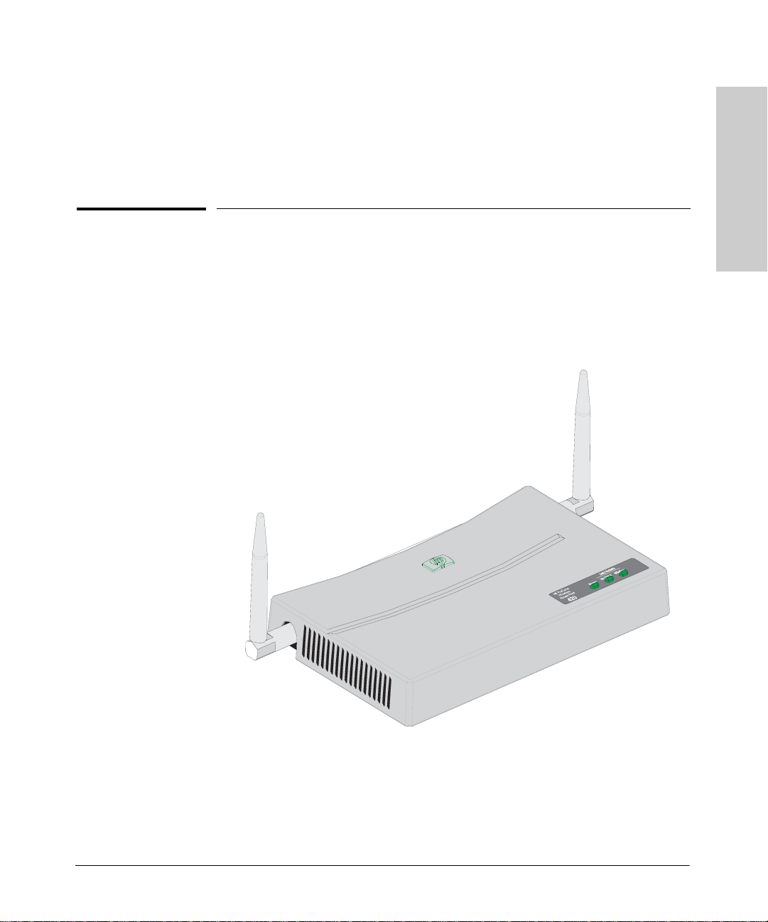
The HP Procurve Access Point 420ww/na is a wireless repeater that seamlessly
integrates with existing wired networks to support connectivity for mobile
users or wireless workstations. This solution offers fast, reliable wireless
connectivity with considerable cost savings over wired LANs. Just install
enough wireless access points to cover your network area, plug wireless cards
into your notebooks or install wireless adapters into your desktops, and start
networking.
hp procurve wireless AP 420 ww/na (J8131A/J8130A)
wireless AP 420 ww/na
1-1
Page 8

Introducing the hp procurve wireless AP 420 ww/na
Throughout this manual, this ac ce ss point will be abbreviated as the
hp procurve wireless AP 420 ww/na.
The AP 420 ww/na has one 10/100Base-TX RJ-45 port. This port also
supports Power over Ethernet based on the IEEE 802.3af standard. The access
point supports wireless connectivity at speeds up to 54 Mbps based on the
IEEE 802.11g standard.
wireless AP 420 ww/na
Introducing the hp procurve
This access point is designed to be used primarily for connecting wireless
clients to an enterprise network. This access point allows wireless clients to
connect directly to each other, or to connect to other computers or ne twork
resources located on the w i red network. In addition, the Ac cess Point 420wl
offers full network managemen t capabilities.
This chapter describes your hp procurve wireless AP 420 ww/na including:
■ Top and back of the a cc ess point
■ Access point features
1-2
Page 9
Introducing the hp procurve wireless AP 420 ww/na
Top of the Access Point
Introducin g the hp procurve
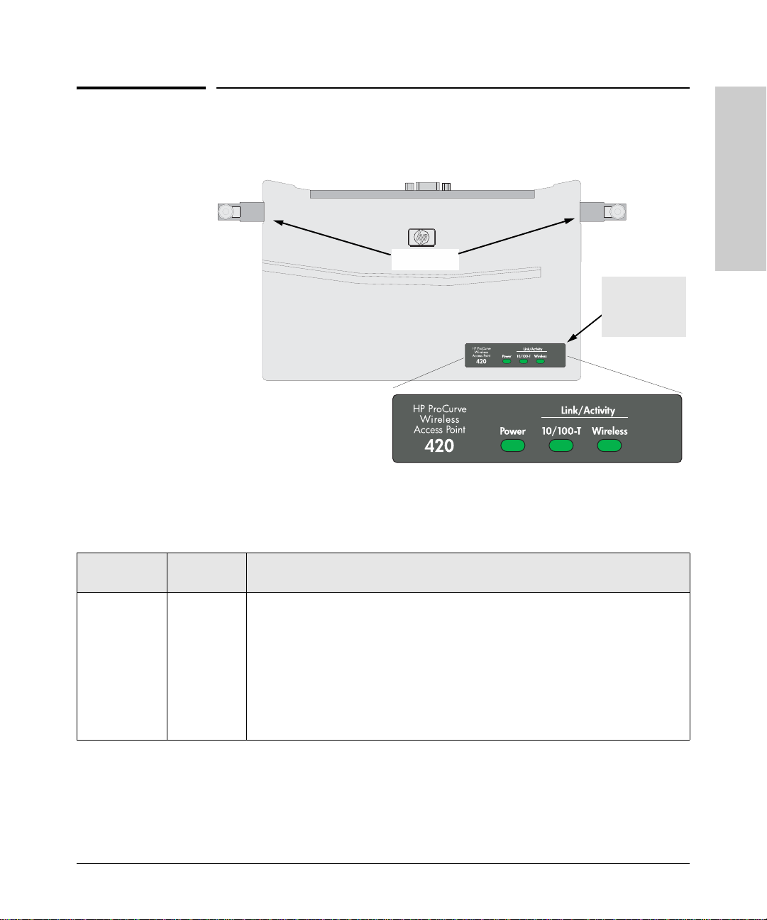
Top of the Access Point
Antennas
LEDs
wireless AP 420 ww/na
hp procurve wireless AP 420 ww/na
Power,
10/100-T Link,
and Wireless
Link LEDs
Access Point
LEDs
Power
(green)
Table 1-1. Access Point LEDs
State Meaning
On The access point is receiving power.
Off The access point is NOT receiv ing power.
Blinking* The access point is undergoing self test or downloading software.
The self test and initialization are in progress after you have power cycled or reset
the access point. The access point is not operational until this LED stops blinking.
Blinking*
(prolonged)
A component of the access point has failed its self test.
1-3
Page 10

Introducing the hp procurve wireless AP 420 ww/na
Top of the Access Point
Access Point
LEDs
10/100-T On (green) The LAN port is enabled and receiving a link indication from 100 Mbps device.
wireless AP 420 ww/na
Introducing thehp procurve
Wireless On The wireless interface is enabled and receiving a link indication from a wireless client
* The blinking behavior is an on/off cycle once every 1.6 seconds, approximately.
State Meaning
On (amber) The LAN port is enabled and receiving a link indication from 10 Mbps device.
Off The LAN port h a s no active network ca ble connected, or is not receiving a link b eat.
Otherwise, the port may have been disabled through the access point console, or the
web browser interface.
Blinking* The LAN port is transmitting or rece iving traffic.
Off The wireless inte rfa ce is not receiving a link beat. Otherwise, the wireless interface
may have been disabled through the access point console, or the web browser
interface.
Blinking* The wireless interface is transmitting or receiving traffic.
1-4
Page 11
Introducing the hp procurve wireless AP 420 ww/na
Back of the Access Point
Introducin g the hp procurve
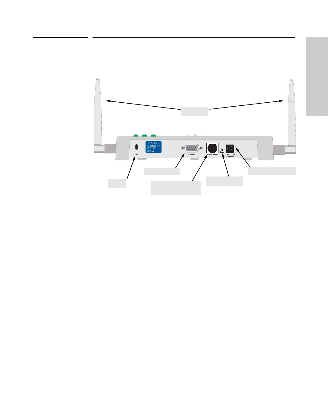
Back of the Access Point
hp procurve wireless AP 420 ww/na
Antennas
Console Port
Lock
10/100Base-TX RJ-45
port and PoE Input
Reset buttons
Antennas
The access point includes two antenna s f or wireless communications. The
outbound signal transmitted from both antennas is identical, but only the best
inbound signal rece ived on one of the an tennas is used. The antenna s transmit
the outgoing signal as a toroidal sphere, so the antennas should be adjusted
to different angles to provide better coverage. For further information on
positioning the antennas, see “Position the Antennas on the Access Point” on
page 2-10.
DC power connector
wireless AP 420 ww/na
Lock
The access point inclu des a Kensington security slot on the rear panel, marked
“Lock”. You can prevent unauthorized removal the access point by wrapping
the Kensington security cable (not provided) around an unmoveable object,
inserting the lock into the slot, and turning the key.
1-5
Page 12

Introducing the hp procurve wireless AP 420 ww/na
Back of the Access Point
Console Port
This port is used to connect a console to the access point by using the serial
cable supplied with the access point. This connection is described under
“Connect a Console to the Access Point” in ch apter 2, “Installing the
Access Point420wl”. The console can be a PC or workstation running a VT- 100
terminal emulator, or a VT-100 terminal.
wireless AP 420 ww/na
Introducing the hp procurve
Network Port
The access point includes one 10/100Base-TX port. This port uses MDI
(i.e., internal straight-through) pin configuration. You can therefore use
straight-through twisted-pai r cable to connec t this port to most network
interconnection device such as switch or router that provide MDI-X ports.
However, if you need to connect the access point to a workstation or other
device that only has MDI ports, then use crossover twisted-pair cable.
Ports on most HP switches have the “HP Auto MDIX” feature, which means
that you can use either straight-through or crossover twisted-pair cables to
connect the access point to these switches.
Refer to following section for information on supplying po wer to the access
point’s network port from a network device, such as a switch, that provides
Power over Ethernet (PoE).
Power Connector
The AP 420 ww/na does not have a power switch; it is powered on when
connected to the AC power adapter, and the power adapter is connected to
an active AC power source. Th e access point automatical ly adjusts to any
voltage between 100--240 volts and either 50 or 60 Hz. There are no voltage
range settings required.
Caution Use only the AC power adapter supplied with the access point. Use of other
adapters, including adapters that came with other HP network products, may
result in damage to the equipment.
The access point may also re ceive P ower over Ethern et (PoE ) from a switc h
or other network device that supplies power over the network cable based on
the IEEE 802.3af standard.
1-6
Page 13

Introducing the hp procurve wireless AP 420 ww/na
Back of the Access Point
Note that if the access point is connected to a PoE source device and also
connected to a local power source through the AC power adapter, PoE will
be disabled.
Reset Button
This button is used to restore the factory default configuration. When the
Reset button is pressed, any configuration changes you may have made
through the access point console, the web browser interface, and SNMP
management are removed, and the factory default configuration is restored to
the access point. For the specific method to restore the factory default
configuration, see “Restoring the Factory Default Configuration” in chapter 4,
“Troubleshooting” of this manual.
Introducin g the hp procurve
wireless AP 420 ww/na
1-7
Page 14

Introducing the hp procurve wireless AP 420 ww/na
Access Point Features
wireless AP 420 ww/na
Introducing the hp procurve
Access Point Features
The wireless features of the Access Point 420ww/na include:
■ supports up to 64 wireless clients.
■ 802.11g draft Compliant – interoperable with multiple vendors.
■ provides seamless roaming within 802.11g draft WLAN environment.
■ precise control over signal transmission power and data rate.
■ advanced security through 64/128-bit WEP encryption, Wi-Fi Protected
Access (WPA), 802.1x, remote authentication via RADIUS server, and
MAC address fil ter ing features to protect your sensitive data an d a uthenticate only authorized users to your network.
■ remote logging of system messages.
■ time synchronization via SNTP server for message logs.
■ supports PPP dial-in connection using standard dial-up program.
The other basic features of the Access Point 420ww/na include:
■ one 10/100Base-TX RJ-45 port.
■ supports Power over Et hernet based on the IEEE 802.3af standard.
■ automatic learning of the network addresses in the access point’s address
forwarding table.
■ full-duplex operation for the 10/100 RJ-45 port when connected to other
auto-nego tiating devi ces.
■ easy management of th e access point through sever al available interfac es:
• console interface—a full featured, easy to use, VT-100 terminal
interface that is e specially goo d for out-of-b and access point management or for Telnet access to the access point.
• web browser interface—an easy to use built-in graphical interface
that can be accessed from common web browsers.
■ support for one IEEE 802.1Q-compliant VLAN so the access point can join
the appropriate logical grouping that fits your business needs.
■ support for many advanced features to enhance network performance—
for a description , see the Management and Configuration Guide, which
is on the Documentation CD-ROM that is included with your access point.
■ download of new access point software for product enhancements or bug
fixes.
1-8
Page 15

2
Installing the hp procurve wireless AP 420 ww/na
The HP Access Point 420ww/na is easy to install. It comes with an accessory kit
that includes a bracket for mounting the access point on a wall. The bracket
is designed to allow mounting the access point in a variety of locations and
orientations.
This chapter shows you how to install your Access Point 420ww/na.
Included Parts
The AP 420 ww/na has the following components shipped with it:
■ hp procurve wireless AP 420 ww/na Installation and Getting Started Guide
(J8130-90001), this manual
■ HP Procurve Product Documentation CD-ROM
(contains PDF file copies of the documentation for th e
Access Point 420ww/na, including the Management and Configuration
Guide)
■ Console cable
■ Customer Support/Warranty booklet
■ Accessory kit (5064-2 085 ?)
• one mounting bracket
• four 5/8-inch number 12 wood screws to attach the access point to a
wall
• four plastic wall plugs for mounting on brick or concrete wall
• four rubber feet
■ AC power adapter, one of the following:
wireless AP 420 ww/na
Installing the
Australia/New Zealand
China
Continental Europe
Denmark
Japan
Switzerland
United Kingdom/Hong Kong/Singapore
United States/Canada/Mexico
8120-6803 ?
8120-8377
8120-6802
8120-6806
8120-6804
8120-6807
8120-8709
8120-6805
2-1
Page 16

Installing the hp procurve wireless AP 420 ww/na
Installation Procedures
Installing the
wireless AP 420 ww/na
Installation Procedures
Summary
Follow these easy steps to install your access point. The rest of this chapter
provides details on these steps.
1. Prepare the installation site (page 2-4). Make sure that the physical
environment into which you will be installing the access point is properly
prepared, includ ing havi ng the corr ect netwo rk cabli ng ready to connect
to the access point and having an appropriate location for the access
point. Please see page 2-3 for some installation precautions.
2. Verify that the access point passes self test (page 2-5). This is a
simple process of plugging the access point into a power source, or into
a switch that provides Power over Ethernet, and observing that the LEDs
on the access point’s front panel indicat e correct ac cess point ope ration.
3. Mount the access point ( page 2-7). The Access Point 420ww/na can be
mounted on a wall, or on a horizontal surface.
4. Connect power to the a ccess point (page 2-9). Once the access point
is mounted, plug it into the nearby main power source, or into a switch
that provides Power over Ethernet.
2-2
5. Connect to the networ k (page 2-10). Using the ap pro priate ne twork
cable, connect th e acce ss point t o a n etwork conn ecti on poi nt, su ch as a
switch.
6. Position the antennas on the access point (page 2-10). Position
each antenna along a different axis to enhance signal coverage.
7. Connect a console to the ac cess poin t (opt ion al—page 2-11). You
may wish to modify the access point’s configuration, for example, to
configure an IP address so it can be managed using a web browser, from
an SNMP network management station, or through a Telnet session.
Configuration ch ange s can be m ade easily by using the i ncl uded c onso le
cable to connect a PC to the access point’s console port.
At this point, your access point is fully installed. See the rest of this chapter if
you need more detailed information on any of these installation steps.
Page 17

Installing the wireless AP 420 ww/na
Installation Procedures
Installation Precautions:
Follow these precautions when installing your HP Access Point 420ww/na.
Cautions ■ Make sure that the power source circuits are properly grounded, then use
the power adapter supplied with the access point to connect it to the
power source.
■ You can alternatively power the access point through a network connec-
tion to a switch or other network connection device that provides Power
over Ethernet. However, note that if the access point is connected to a
power source, Power over Ethern et will be disabled.
■ Use only the AC power adapter supplied with the access point. Use of
other adapters, including ada pt ers that came with other HP network
products, may result in damage to the equipment.
■ When installing the access point, note that the AC outlet should be near
the access point and should be easi ly accessi ble in case the access po int
must be powered off.
■ Ensure that the access point does not overload the power circui ts, wiring,
and over-current protection. To determine the possibility of overloading
the supply circuits, add together the ampere ratings of all devices installed
on the same circuit as the access point and compare the total with the
rating limit for the circuit. The maximum ampere rat ings are usually
printed on the devices near the AC power connectors.
■ Do not install the access point in an environment where the operating
ambient temperature might exceed 55°C (131°F).
■ Make sure the air flow around the sides of the access point is not
restricted.
wireless AP 420 ww/na
Installing the
2-3
Page 18

Installing the wireless AP 420 ww/na
Installation Procedures
1. Prepare the Installation Site
■ Cabling Infr astructure - Ensure th at the cabling infrastructure meets
the necessary network specifications. See the following table for cable
types and lengths, and see appendix B, “Access Point Port and Network
Cables” for more information:
Table 2-1. Summary of Cable Types to Use With the Access Point
Port Type Cable Type Length Limits
Twisted-Pair Cables
10/100Base-TX • 10 Mbps operatio n:
Installing the
wireless AP 420 ww/na
100 meters
Category 3, 4, or 5, 100-ohm unshielded
twisted-pair (UTP)
• 100 Mbps operation:
Category 5, 100-ohm UTP or shielded
twisted-pair (STP) cable.
■ Installation Lo cation - Before installing the access point, plan its loca-
Note: Since the 10Base-T operation is through
10/100Base-TX ports, if you ever want to
upgrade the ports to 100Base-TX, it would be
best to cable the por ts initially with catego ry 5
cable.
The 10/100-Base-TX port on the
Access Point 420ww/na uses an MDI pin
configuration, which requires yo u to use
straight-through cable when connecting to
another device that has an MDI-X port, or
crossover cable when connecting to a device
that has an MDI port. However, if the device to
which you are connecting supports autoMDIX, then you can use either straightthrough or crosso ver cable.
tion and orientation relative to other devices and equipment:
• Try to pla ce th e access point in the center of your wireless network .
Normally, the higher you place the antenna, the better the performance. You may need to reposition the access poin t after testing the
signal strength on several wireless clients to ensure that the access
point’s location provides optimal recept ion throughout your offic e.
• In the back of the access point, leave at lea st 7.6 cm (3 inches) of space
for the twisted-pair cabling and the power cord.
• On the sides of the access point, leave at least 7.6 cm (3 inches) for
cooling.
2-4
Page 19

Installing the wireless AP 420 ww/na
Installation Procedures
3. Verify the Access Point Passes the Self Test
Before mounting the acce ss point in its network location, you should first
verify that it is working properly by plugging it into a power source, or a switch
that provides Power over Ethernet, and verifying that it passes its self test.
1. Connect a network cable from a PoE source device (such as a switch) to
the RJ-45 jack on the back of the access point, or connect the power
adapter supplied with the access point to the power connector on the back
of the access point, and then into a properly grounded el ectrical outlet.
Connect network
cable to PoE switch
Note The AP 420 ww/na does not have a power switch. It is powered on when
the power adapter is connected to the access point and to a power source, or
when a network cable is connected to the access point and to a network device
that provides Power over Ethernet. For safety, when connecting to an electrical outlet, the power outlet should be located near the access point.
Or connect power adapter
to the power connector
wireless AP 420 ww/na
Installing the
Use only the AC power adapter supplied with the access point. Use of other
adapters, including adapters that came with other HP network products, may
result in damage to the equipment.
2-5
Page 20
Installing the wireless AP 420 ww/na
Installation Procedures
Installing the
wireless AP 420 ww/na
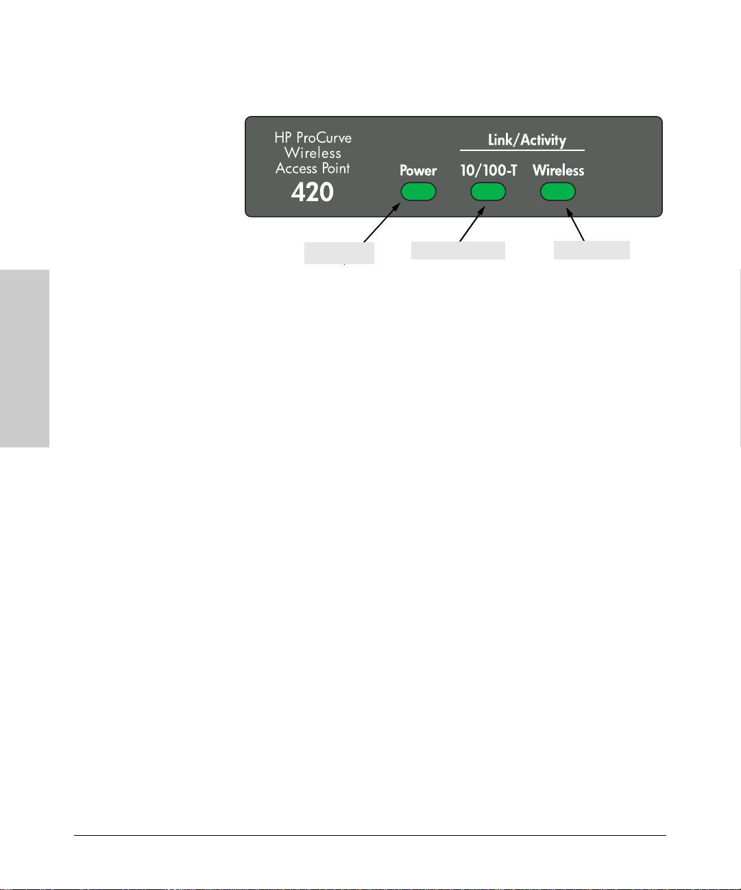
2. Check the LEDs on the
Power LED
access point as described below.
Ethernet LED
Wireless LED
When the access point is powered on, it performs its diagnostic self test.
The self test takes approximately 50 seconds to complete.
LED Behavior:
During the self test:
• The 10/100BASE-T and Wireless LEDs go off and then may come on
again during phases of the se lf test. For the duration of the self test,
the Power LED blinks.
When the self test completes successfully:
•The Power LED remains on.
•The 10/100BASE-T and Wireless LEDs on the top of the access point go
into their normal operational mode:
– If the ports are connected to active network devices, the LEDs
should be on.
– If the ports are not connected to active network devices, the LEDs
will stay off.
2-6
If the LED display is different than what is described above, especially if
the Power LED does not stop blinking, the self test has not completed
correctly. Refer to chapter 4, “Troubleshooting” for diagn o stic help.
Page 21

Installing the wireless AP 420 ww/na
Installation Procedures
4. Mount the Access Point
After you have veri fied that the access poin t passes the self test, you are ready
to mount the access point in a stable location. The Access Point 420ww/na can be
mounted in these ways:
■ on a wall
■ on a horizontal surface
Wall Mounting
Y ou can mount the access point on a wall as shown in the illustrations on the
next page.
Caution The access point should be mounted only to a wall or wood surface that is at
least 1/2-inch plyw ood or its equivalent.
1. Position the mounting bracket on the wall, and ma rk the holes.
2. T o moun t the access point on a plastered b rick or conc rete wall, fi rst drill
four holes 22 mm deep and 3.5 mm in diameter, and press the included
four wall plugs firmly into the drilled holes until they are flush with the
surface of the wall.
3. Set the four 5/8-inch number 12 wood screws in the holes, leaving about
3 mm (0.12 in.) clearance from the wall.
4. Position the mounting bracket over the wall screws, slide the bracket onto
the screws, and then tight en down the screws.
5. Slide the access point into the protruding slots on the back of the
mounting bracket. The two retaining latches will slip into place over the
back edge of the access point.
6. To prevent unauthorized removal of the ac cess point, you can use a
Kensington Slim MicroSaver security cable (not included) to attach the
access point to an immovable object.
wireless AP 420 ww/na
Installing the
2-7
Page 22

Installing the wireless AP 420 ww/na
Installation Procedures
wood screws
Installing the
wireless AP 420 ww/na
Mounting the Bracket on a Wall Sliding the Access Point onto the Bracket
5/8-inch
2-8
Page 23

Installing the wireless AP 420 ww/na
Installation Procedures
Horizontal Surface Mounting
Place the access po int on a ta ble or other horizontal su rface. The a ccess point
comes with rubber feet in the accessory k it that can be used to h elp keep the
access point from sliding on the surface.
Attach the rubber feet to the four corners on the bottom of the access point
within the embossed lines. Use a sturdy surface in an uncluttered area. You
may want to secure the networking cable and access point’s power cord to
the table leg or other part of th e surface structur e to help prevent t ripping over
the cords.
Caution Make sure the air flow is not restricted around the sides of the access point.
5. Connect the Access Point to a Power Source
1. Plug the i ncluded po wer adapter into the access poin t’ s power co nnector
and into a nearby AC power source.
Or, al ternatively , connect the Ethernet por t on the access point to a switch
or other network device that provides Power over Ethernet.
2. Re-check the LEDs during self test. See “LED Behavi or” on page 2-6.
wireless AP 420 ww/na
Installing the
2-9
Page 24

Installing the wireless AP 420 ww/na
Installation Procedures
6. Connect the Network Cable
Connect the network cable, described under “Cabling Infrastructure”
(page 2-4), from the network device or your patch panel to the RJ-45 port on
the access point.
Using the RJ-45 Connectors
To connect:
Push the RJ-45 plug into the RJ-45
jack until the tab on the plug clicks
into place. When powe r i s on for the
access point and for the connected
device, the 10/100BASE-T link LED
should light to confirm a powered-on
device (for example, an end node) is
at the other end of th e cable.
RJ-45 connector
Installing the
wireless AP 420 ww/na
If the 10/100BASE-T link LED does
not go on when the network cable is
connected to the port, see “Diagnosing with the LEDs” in chapter 4,
“Troubleshooting”.
Unshielded twisted-pair cable:
• Category 3, 4, or 5 for 10 Mbps ports
• Category 5 or better for 100 Mbps ports
Maximum distance: 100 meters
To disconnect:
Press the small tab on the plug a nd pull the plug out of the jack.
7. Position the Antennas on the Access Point
The antennas emit signals along a toroidal plane – and thus provide more
effective co verage when positioned alo n g alternate axes. For example , you
might position the antennas around 45 to 90 degrees from each other.
The access point also compares the strength of an incoming signal on both
antennas, and uses the a ntenna receivin g the stronger signal to communi cate
with a wireless client.
2-10
Page 25

Installing the wireless AP 420 ww/na
Installation Procedures
8. (Optional) Connect a Console to the
AP 420 ww/na
The AP 420 ww/na has a full-featured, easy to use console interface for
performing access point manag ement tasks including the following:
■ Modify the access point’s configuration to optimize access point perfor-
mance, enhance networ k tr affic control, and improve network security
■ Download new software to the access point
■ Add passwords to control access to the access point from the console,
web browser interface, an d network management stations
The console can be accesse d through these methods:
■ Out-of-Band: The AP 420 ww/na comes with a serial cable for
connecting a PC or VT-100 terminal, to be used as a console, directly to
the access point.
■ In-Band: Access the console using Telnet from a PC or UNIX station on
the network, and a VT-100 terminal emulator. This method requires that
you first configure the access point with an IP address and subnet mask
by using either out-of-b and console access or through DHCP. For more
information on IP addressing and on starting a Telnet session, see
chapter 3, “Getting Starte d With Access Point C onfiguration”, and the
Management and Configuration Guide, which is on the Docume ntation
CD-ROM that came with your access point.
wireless AP 420 ww/na
Installing the
The AP 420 ww/na can simultaneously support one out-of-band console
session through the Console Port and four in-band Telnet console sessions.
Terminal Configuration
T o connect a conso le to the access point, co nfigure the PC termi nal emulator
as a DEC VT -100 (ANS I) terminal or use a VT -100 terminal, and configure either
one to operate with these settings:
• 9600 baud
• 8 data bits, 1 stop bit, no par ity, and flow control set to None
• For the Windows Terminal program, also disable (uncheck) the “Use
Function, Arrow, and C
• For the Hilgraeve HyperTerminal program, select the “Terminal keys”
option for the “Function, arrow, and ctrl keys act as” parameter
You can only attach to the console using these configuration settings.
trl Keys for Windows” option ?
2-11
Page 26

Installing the wireless AP 420 ww/na
Installation Procedures
Installing the
wireless AP 420 ww/na
Direct Console Access
To connect a console to the
access point, follow the se steps:
1. Connect the PC or terminal
to the access point’s
Console port using the
console cable included with
the AP 420 ww/na. (If
your PC or terminal has a
25-pin serial con nector, fir st
attach a 9-pin to 25-pin
straight-thro ug h ad ap ter at
one end of the console
cable.)
PC running a terminal
emulator program, or
2. T urn on the termin al or PC’ s
power and, if using a PC,
start the PC terminal
program.
3. Enter “admin ” at the “Username:” prom pt, and press the [Enter] key at the
“Password” prompt. You will then see the access point console command
(CLI) prompt, for examp le:
Console port
Console cable supplied
with the access point
a VT-100 terminal
2-12
hp procurve wireless AP 420 ww/na
If you want to continue with console management of the access point at this
time, see chapter 3, “Getting Starte d With Access Point Configuration” for
some basic configuration steps. For more detailed information, ref er to the
Management and Configuration Guide, which is on the Documenta t i on
CD-ROM that came with your access point.
Page 27

Installing the wireless AP 420 ww/na
Sample Network Topologies
Sample Network Topologies
This section shows you a few sample network topologies in which the
Access Point 420ww/na is implemented. The wireless solution supports a standalone wireless network configuration as well as an integrated configuration
with wired Ethe rnet LANs. Wireless network cards, adapters , and access
points can be configured a s :
■ Ad hoc for departmental or SOHO LANs
■ Infrastructure for wireless LANs
■ Infrastructu re wireless LAN for roaming wireless PCs
For more topology information, see the HP network products World Wide W eb
site, http://www.hp.com/go/hpprocurve.
Ad Hoc Wireless LAN (no access point)
wireless AP 420 ww/na
Installing the
Notebook with
Wireless USB Adapter
Notebook with
Wireless PC Card
PC with
Wireless PCI Adapter
An ad-hoc wireless LAN consists of a group of computers, each equipped with
a wireless ad apter, connected via rad i o signals as an in dependent wireless
LAN. Computers in a specific ad-hoc wireless LAN must therefore b e c onfigured to the same radio channel. An ad-hoc wireless LAN can be used for a
branch office or SOHO operation.
2-13
Page 28

Installing the wireless AP 420 ww/na
Sample Network To pologies
Installing the
wireless AP 420 ww/na
Desktop PC
Infrastructure Wireless LAN
File
Server
Switch
AP 420 ww/na
wireless PCI
Adapter
Wired LAN Extension
to Wireless Adapters
Notebook with
wireless PC
Card Adapter
PC with
2-14
The Access Point 420ww/na can provide access to a wired LAN for wireless
clients. An integrated wired/wireless LAN is called an Infrastructure configuration. A Basic Service Set (BSS) consists of a group of wireless PC users, and
an access point tha t is directly co nnected to the wir ed LAN. Each wi reless PC
in this BSS can talk to any computer in its wireless group via a radio link, or
access othe r computers or network reso urces in the wired LAN infr astructure
via the acces s point.
The infrastructure configuration not only extends the accessibility of wireless
PCs to the wired LAN, but also increases the effective wireless transmission
range for wireless PCs by passing their signal through one or more access
points.
A wireless infrastructure can provide an extension of the wired LAN to
wireless clients for access to a local resources, or for a bridged connection
between mobile workers loca ted at distant points on the netwo rk.
Page 29

Desktop PC
Installing the wireless AP 420 ww/na
Sample Network Topologies
Infrastructure Wireless LAN for Roaming Wireless PCs
Seamless Roaming
File
Server
Switch
Wireless Clien t
Switch
Wireless Client
AP 420 ww/na
<BSS2>
wireless AP 420 ww/na
Installing the
AP 420 ww/na
<BSS1>
Wireless Client
<ESS>
The Basic Service Set (BSS) is the communications domain for each access
point and its associated wireless clients. For wireless PCs that do not need to
support roaming, set the Serv ice Set Identi fier (SSID) for th e wireless card to
the BSS ID of the access point to which you want to connect.
Check with your administrator for the BSS ID of the access point to which you
should connect. A wireless infrastructure can also support roaming for mobile
workers. More th an one access poi nt can be conf igured to crea te an Extended
Service Set (ESS). By placing the access points so that a continuous coverage
area is created, wireless user s within this ESS can roam freely . All HP wirel ess
network cards and adapter s and ac cess points wi thin a spec ifi c ESS must be
configured with the same SSID.
2-15
Page 30

Installing the wireless AP 420 ww/na
Sample Network To pologies
Installing the
wireless AP 420 ww/na
2-16
Page 31

Getting Started With Access Point Configuration
This chapter is a guide for using the access point’s console to quickly assign
an IP (Internet Protocol) address and subnet mask to t he access point, set a
Manager password, and, optionally, configure other basic features.
For more informati on on using the access point’ s console and the o ther access
point management interfaces: the web browser interface and SNMP management tools, please see the Management and Configuration Guide, which is
on the Documentation CD-ROM that came with your access point.
Recommended Minimal Configuration
In the factory default configuration, the access point has no IP (Internet
Protocol) address and subnet mask, and no passwords. In this state, it can be
managed only through a direct console connection. To manage the access
point through in-band (networked) access, you should configure the access
point with an IP address and subnet mask compatible with your network. Also,
you should configure a Ma nager password to control acce ss privileges from
the console and web browser interface. Other parameters can be left at their
default settings or you can configure them with values you enter.
3
Getting Started With Access
Point Configuration
Many other features can be configured through the acc ess point’s console
interface, to optimize the access point’s per formance, to enhance your contro l
of the network traffic , and to improve network securit y. Once an IP address
has been configured on the access point, these featur es can be accessed more
conveniently through a remote Telnet session, through the access point’s web
browser interface, and from an SNMP network management station running
a network management program. For a listing of access point features available with and without an IP address, refer to “How IP Addressing Affects
Access Point Operation” in the Management and Configuration Guide,
which is on the Documentation CD-R OM t hat came with your access point.
For more information on IP a ddressing, refer to “IP Configurat ion” in the
Management and Configuration Guide.
3-1
Page 32

Getting Started With Access Point Configuration
Note By default, the access poin t i s confi g ur ed to acquire an IP address configura-
tion from a DHCP server. To use DHCP instead of the manual method
described in this chapter, see “DHCP Operation” in the Management and
Configuration Guide, which is on the Documentation CD-ROM that came
with your access point.
Using the Command Line Interface
The quickest and easies t way to minimally configure the access point for
management and password protection in your network is to use a direct
console connection to t he access point, start a console session, and access
the command line interface (CLI).
1. Using the metho d described in th e preceding chapter , con nect a terminal
device to the access poin t, and press [Enter] to initiate the console
connection.
2. Enter “admin” for the user name. The default password is null, so just
press [Enter] at the password prompt. The CLI prompt appears displaying
the access point’s model number.
Username: admin
Password:
HP Procurve Access Point wl420#
Getting Started With Access
3. Ty pe configure to enter global configuration mode.
HP Procurve Access Point wl420#configure
Enter configuration commands, one per line. End with CTRL/Z
HP Procurve Access Point wl420(config)#
4. Ty pe username username to create a user name for the Manager, where
Point Configuration
“username” can consist of 3 to 16 alphanumeric characters and is case
sensitive.
HP Procurve Access Point wl420#configure
Enter configuration commands, one per line. End with CTRL/Z
HP Procurve Access Point wl420(config)#username admin
HP Procurve Access Point wl420(config)#
5. Ty pe password password to create a password for the Manager, where
“password” can consist of up to 8 alphanumeric characters and is case
sensitive.
HP Procurve Access Point wl420#configure
Enter configuration commands, one per line. End with CTRL/Z
HP Procurve Access Point wl420(config)#password [password]
HP Procurve Access Point wl420(config)#
3-2
Page 33

Getting Started With Access Point Configuration
6. Ty pe end to exit configuration mode, and then enter the show interface
ethernet command to display the access point’s default IP configuration,
including IP address, subnet mask, and de f ault gateway. The following
illustration shows the default settings.
HP Procurve Access Point wl420#show interface ethernet
Ethernet Interface Information
========================================
IP Address : 0.0.0.0
Subnet Mask : 255.255.255.0
Default Gateway : 0.0.0.0
Primary DNS : 0.0.0.0
Secondary DNS : 0.0.0.0
Speed-duplex : 100Base-TX Full Duplex
Admin status : Up
Operational status : Up
HP Procurve Access Point wl420#
7. Ty pe configure to enter configuration mode, then type interface ethernet to
access the Ethernet interface-configuration mode.
HP Procurve Access Point wl420#configure
HP Procurve Access Point wl420(config)#interface ethernet
Enter Ethernet configuration commands, one per line.
HP Procurve Access Point wl420(if-ethernet)#
8. Ty pe ip address ip-address netmask gateway, where “ip-address” is the
access point’ s IP address, “netmask” is the network mask fo r the network,
and “gateway” is the default gateway router. Check with your system
administrator to obtain an IP address that is compatible with your
network.
Getting Started With Access
Point Configuration
HP Procurve Access Point wl420(if-ethernet)#ip address 192.168.1.1
255.255.255.0 192.168.1.254
3-3
Page 34

Getting Started With Access Point Configuration
9. Ty pe exit to leave configuration mode, then enter the show interface
wireless g command to display the access point’s default wireless config-
uration, including wire less communication domai n, radio channel, and
operation status. The following illustrat ion shows the default settings.
HP Procurve Access Point wl420(if-ethernet)#exit
HP Procurve Access Point wl420#show interface wireless g
Wireless Interface Information
===========================================================
----------------Identification----------------------------Description : Enterprise 802.11g Access Point
SSID : Enterprise Wireless AP
Channel : 0 (AUTO)
Status : Disable
----------------802.11 Parameters-------------------------Transmit Power : FULL (17 dBm)
Max Station Data Rate : 54Mbps
Fragmentation Threshold : 2346 bytes
RTS Threshold : 2347 bytes
Beacon Interval : 100 TUs
DTIM Interval : 2 beacons
Maximum Association : 64 stations
----------------Security----------------------------------Closed System : DISABLED
Multicast cipher : WEP
WPA clients : SUPPORTED
Encryption : DISABLED
Default Transmit Key : 1
Static Keys :
Key 2: EMPTY Key 3: EMPTY Key 4: EMPTY
Authentication Type : OPEN
===========================================================
HP Procurve Access Point wl420#
Getting Started With Access
10. Type configure to return to global configuration mode, and then type
interface wireless g to access the wireless interface-configuration mode.
HP Procurve Access Point wl420#configure
HP Procurve Access Point wl420(config)#interface wireless g
HP Procurve Access Point wl420(if-wireless g)#
Point Configuration
11. Set the Service Set Id entifier (SSID) to identify the communications
domain for the acce ss point. Type ssid identifier, where “identifier” can
consist of up to 32 alphanume ric characters and is case sensitive.
HP Procurve Access Point wl420(if-wireless g)#ssid wl420
HP Procurve Access Point wl420(if-wireless g)#
3-4
Page 35

12. Set the radi o channel through whi ch the access point comm unicates with
13. Type no shutdown to enable wireless operation.
14. Type Ctrl-Z to save your set tings.
Here is some information on the basic IP address and wireless configuration
parameters. For more information on these fields, see the Management and
Configuration Guide, which is on the Documentation CD-ROM that came
with your access point:
Parameter Default
Getting Started With Access Point Configuration
its wireless clients. For most wireless clients, the radio channel is automatically set to the same as that used by the access point to which it is
linked. Type channel number, where “num ber” can be from 1 to 11,
depending on the wireless regulations specified by your country.
HP Procurve Access Point wl420(if-wireless g)#channel 9
HP Procurve Access Point wl420(if-wireless g)#
HP Procurve Access Point wl420(if-wireless g)#no shutdown
HP Procurve Access Point wl420(if-wireless g)#
Username admin The name of the Manage r.
Password none The password for the Manager.
IP Address 0.0.0.0 IP address compatible with your network.
Subnet Mask 255.255.255.0 Subnet mask compatible with your network.
Default Gateway 0.0.0.0 IP addr ess of the next-ho p gateway node for network traffic tha t needs to be
able to reach off-subnet destinations.
SSID ANY The Service Set Identifier is a unique name identifying the commu nications
domain for the access point. Clients that want to connect to the wireless
network via this specific ac cess point must set their SSIDs to the same name.
Channel 0 (AUTO) The radio channel through which the ac cess point communica tes with its
wireless clients. For most wireless clients, the radio channel is automatically
set to the same as that used by the access point to which it is linked.
Wireless Operation Disabled Wireless opera t io n sh ould be enabled only after you co nfi gure the
appropriate SSID and radio channel using the no shutdown command.
Note: The IP address and subnet mask assigned for the access point must be compatible with the IP addressing used
in your network. For m or e info r m ation on IP addressing, see the Management and Configuration Guide, which is on
the Documentation CD - RO M that came with your access point.
Getting Started With Access
Point Configuration
3-5
Page 36

Getting Started With Access Point Configuration
Where to Go From Here
The above procedure using the CLI configured your access point with a
Manager password, IP address, and subnet mask. As a result, with the proper
network connections, you can now manage the access poi nt from a PC
equipped with Telnet, a web browser interface, or from an SNMP-based
network management station. The above procedure also configured the
Service Set Identifier (SSID), radio channel, and enabled wireless operation.
Your wireless clients can now access the network by setting their SSID and
radio channel to the same values used by the access point.
Some basic information on managing your access point is included in the next
section. For more information on the console, web browser, and SNMP
management interfaces, and all the features that can be configured on the
Access Point 420wl, please see the Management and Configuration Guide,
which is on the Documentation CD-R OM t hat came with your access point.
To Recover from a Lost Manager Password: If you cannot start a console session because of a lost Manager password, you can clear all passwords
and user names by getting physical access to the access point and pressing
and holding the Reset button for a ful l second . However, note that th is acti on
will reset all configuration settings to the factory defaults.
Getting Started With Access
Point Configuration
3-6
Page 37

Using the IP Addr ess for Remote Access Point Management
Getting Started With Access Point Configuration
Using the IP Address for Remote Access
Point Management
With your Access Point 420ww/na, you can use the access point’s IP address to
manage the access poin t from any PC that is o n the same subnet as the access
point. You can use either a Telnet session or a standard web browser to manage
the access point.
Starting a Telnet Session
To access the access point through a Telnet session, follow these steps:
1. Make sure the access point is configured with an IP address and that the
access point is reachable from the PC that is running the Telnet session
(for example, by using a Pin g comm and to the ac cess poi nt’s IP address).
2. Start the Telnet program on a PC that is on the same subnet as the access
point and connect to the access point’s IP address.
3. Enter the user name and password. (The default user name is “admin” and
the default password is null. You will then see the access point’s console
command (CLI) pr ompt, for example:
Username: admin
Password:
HP Procurve Access Point wl420#
Getting Started With Access
Point Configuration
Enter ? to see a list of commands that can be executed at the prompt.
Entering any command followed by ? displays a list of options that are
available at that point in the command entry.
Starting a Web Browser Session
Your AP 420 ww/na can be managed through a graphical interface that
you can access from any PC or workstation on the network by running your
web browser (e.g., Java-enable d I nternet Explorer 5.5) and typin g in the
access point’s IP address as the URL. (See “Using the Command Line Interface” on page3-2 for information on setting the IP address.) No additional
software installation is required to make this interface available; it is included
in the access point’s onboard software.
3-7
Page 38

Getting Started With Access Point Configuration
Using the IP Address for Remote Access Point Management
A typical web browser interface screen is shown in the next illustration.
Getting Started With Access
For more information on us ing the web browser interface, please see the
Management and Configuration Guide, which is on th e D ocumentation
CD-ROM that came with your access point.
An extensive help system is also available for the web browser interface.
Point Configuration
3-8
Page 39

Troubleshooting
This chapter describes how to troubleshoot your HP Procurve
Access Point 420ww/na. Note that this document describes troubleshooting
mostly from a hardware persp ective. You can perf orm mor e in-dep th troubl eshooting on the Access Point 420ww/na using the software tools available with the
access point, including the full-featured console interface, and the built-in web
browser interface, or SNMP-based network management tools. For more
information, see the chapt er “Troubleshooting” in the Management and
Configuration Guide, which is on the Documentation CD-ROM that came
with your access point.
This chapter describes the follow ing :
■ basic troubleshooting ti ps (page 4-1)
■ diagnosing with the LEDs (page 4-3)
■ Proactive Networking tools (page 4-5)
■ hardware diagnostic tests (page 4-6)
■ restoring the factory default configuration (page 4-8)
■ downloading new software to the Access Point420wl (page 4-9)
■ HP Customer Support Services (page 4-9)
4
Basic Troubleshooting Tips
Most problems are cause d by the fol lowi ng situa tions. Ch eck for these ite ms
first when starting your troub leshooting:
■ Connecting to devices th at have a fixed full-dup lex configuration.
The RJ-45 port uses auto- negotiation to de termine the dup lex mode. That
is, when connectin g to at tac he d de vi ce s, th e ac cess po i n t will o p er ate in
one of two ways to determine the link speed and the communication mode
(half duplex or full duplex):
• If the connected device is al so configured to use aut o-negotiation, the
access point will automatically n egotiate both li nk speed and c ommunication mode.
4-1
Troubleshooting
Page 40

Troubleshooting
Basic Troubleshooting Tips
• If the connected device has a fixed configuration, for example
100 Mbps,
at half or full duplex, the access point will automatically
sense the link speed, but will default to a communication mode of half
duplex.
Because the AP 420 ww/na behaves in this way (in compliance with
the IEEE 80 2 . 3 standard), if a device conne cted to the ac cess poin t has
a fixed configuration at full duplex, the device will not connect correctly
to the access point. The result will be high error rates and very inefficient
communications between the access point and the device.
Make sure that all devices connected to the AP 420 ww/na are configured to auto negotiate, or are configured to connect at half duplex (all
hubs are configured this way, for example).
■ Faulty or loose cables. Look for loose or obviously faulty connections.
If they appear to be OK, m ake sure the connecti ons are snug . If that does
not correct the problem, try a different cable.
■ Non-standard cables. Non-standard and miswired cables may cause
network collisions and other network problems, and can seriously impair
network perfor manc e. Use a new c orrectly -wire d cable or comp are your
cable to the cable in appendix B, “Access Point Port and Network Cables”
for pinouts and correct cable wiring. A category 5 cable tester is a
recommended tool for every 100Base-TX network installation.
■ Improper Network Topologies. It is important to make sure you have
a valid network topology. Common topology faults include excessive
cable length and excessive repeater delays between end nodes. If you have
network problems after recent changes to the network, change back to
the previous topology. If you no longer experience the problems, the new
topology is probably at fault. Sample topologies ar e shown at the end of
chapter 2 in this book, and some topology configuration guidelines can
be found online at the HP Procurve web site, http://www.hp.com/go/
hpprocurve.
■ Mobile users cannot connect to the network. Make sure that the
access point and wireless clients are configured to the same WEP setting,
SSID, and authentication algorithm. Check to ensure that the wireless
client is within the maxi mum range supported by the access point. Also
verify that the wireless client has been configured with an IP address
compatible with the attached network, either manually or via DHCP.
Troubleshooting
For more information on possible network problems and their solutions, refer
to the technical note “Troubleshooting LAN Performance and Intermittent
Connectivity Problems”, which can be found on the HP Pr ocurve web site,
http://www.hp.com/go/hpprocurve, in the Information Library section.
4-2
Page 41

Diagnosing with the LEDs
Troubleshooting
Diagnosing with the LEDs
Table 4-1 shows LED patterns on the access point that indicate problem
conditions.
1. Check in the table for the LED pattern that you see on your access point.
2. Refer to the corresponding diagnostic tip on the next few pages.
Table 4-1. LED Error Indicators
LED Pattern Indicating Problems
Power Wireless LED 10/100-T LED
Off with power cord plugged in * *
Off without power cord plugged in,
but linked to a PoE source
Prolonged Bli nking
On Off *
On * Off with cable
On * On, but th e port is not
* This LED is not important for the diagnosis.
†
The blinking beha vior is an on/off cycl e once every 1.6 seconds , approximately.
†
**
Diagnostic Tips:
Tip Problem Solution
The access po int
1
is not plugged
into an active AC
power source, or
the access
point’s power
supply may have
failed.
1. Verify that the power cord is plugged into an active power source and to the access
point. Make sure the s e co nnections are snug.
2. Try power cycling the access point by unplugging and plugging the power cord back in.
3. If the P ower LED is still not on, ve rify that the AC power source works by plugging
another device into the outlet. Or try plugging the access point into a different outlet
or try a different power cord.
If the power source and power cord are OK and this condition persists, the access point’s
power supply may have failed. Call your HP-authorized LAN dealer, or use the electronic
support services from HP to get assistance. See the Customer Support/Warranty booklet
for more information.
Diagnostic
Tips
1
2
3
4
5
connected
6
communicating
Troubleshooting
4-3
Page 42

Troubleshooting
Diagnosing with the LE Ds
Tip Problem Solution
The access poin t
2
is not receiving
power from the
PoE source.
The access po int
3
has experienced
a software
failure during s elf
test.
Wireless link has
4
been
administratively
disabled.
The
5
10/100Base-T
network
connection is not
working
properly.
The port may be
6
improperly
configured.
1. Verify that acce ss point’s 10/100Base-T port is attached to a PoE source device.
2. Verify that the Po E s ou r ce dev i ce is powered on, and that the PoE fun ction has been
administratively enabled on the source port attached to the access point.
3. Refer to Tip 6 to verify that the network cable is functio ning properly.
1. Try resetting the access point by pressing the Reset button on the back of the access
point, or by power cycling the access point.
2. If the fault indication reoccurs, attach a console to the access point (as indicated in
chapter 2). Then, res e t the access point. Messages should appear on the console
screen and in t he console log identi fying the erro r condition . Y ou can v iew the cons ole
log at that point by using the show logging commands.
If necessary to resolve the problem, contact your HP-authorized LAN dealer, or use the
electronic suppor t services from HP to get assistance. See the Customer Support/
Warranty booklet for more information.
Verify that the wireless port has not been disabled through a access point configuration
change. You can use the console in terface, or, if you have configured an IP address on
the access poin t, use the web browser interface to determine the state of the wireless
port and re-enab le the port if necessary.
Try the following procedures:
• Verify th at both ends of the cabl ing, at the acce ss point a nd the c onnected device, are
connected prope r ly.
• Verify the connected device and access point are both powered on and operati ng
correctly.
• If the other pr ocedures don’t resolve the problem, try using a different cable.
VLAN configuration may affect the port operation. Use the access point’s console to see
how the port is configured for VLANs.
For software troubleshooting tips, see the chapter “T roubleshooting” in the Management
and Configuration Guide, which is on the Documentation CD-RO M that came with your
access point.
Make sure also, that the device at the other end of the connection is indicating a good
link to the access point. If it is not, the pro blem may be with the cabling between th e
devices or the connectors on the cable.
Troubleshooting
4-4
Page 43

Troubleshooting
Proactive Netwo r k ing
Proactive Networking
The following interfaces provide tests, indicators, and an event log that can
be used to monitor the access point and its network connections and to help
you take advantage of these proactive networking features:
■ A graphical web browser interface th at you can use to manage your access
point from a PC running a supported web browser, for example Microsoft
Internet Explorer.
■ A full-featured easy-to-use console interface that you can access by
connecting a stand ard termi nal or PC r unnin g a te rmin al emu lato r to the
access point’s console port. The cable to make that connection is provided
with your access point. The console interface is also accessible through
a Telnet connection.
For more information on using these software tools to diagnose and manage
your access point, see the “T roublesho oting” chapter in the Management a nd
Configuration Guide, which is on the Documentation CD-ROM that came
with your access point.
4-5
Troubleshooting
Page 44

Troubleshooting
Hardware Diagnostic Tests
Hardware Diagnostic Tests
Testing the Access Point by Resetting It
If you believe that the access point is not operating correctly, you can reset
the access point to test its circuitry and operating code. To reset an access
point, either
■ Unplug and plug in the power cord (power cycling)
■ Press the Reset button on the bac k of the switch
Power cycling the a ccess poin t and p ressing t he Re set bu tton bo th cause the
access point to perform its power-on self test, which almost always will
resolve any temporary operational problems. These reset processes also
cause any networ k tra ffi c counters to be reset to zer o , an d ca use th e System
Up Time timer to reset to zero.
Checking the Access Point’s LEDs
The self test passes if the Power LED on the front of the access point stops
blinking after approximately 50 seconds. If this LED continues blinking longer
than 60 seconds or goes off, there may be a problem with the access point.
See “Diagnosi n g with the LEDs” on page 4-3 for information on interpreti ng
the LED patterns.
Checking Console Messages
Useful diagn ostic messages ma y be displa yed on the co nsole scree n when the
access point is reset. As described in chapter 2 under step 7, “Connect a
console to the acce ss point”, connect a PC ru nning a VT -100 terminal emulator
program or a standard VT-100 terminal to the access point’s Console Port and
configure it to ru n a t 960 0 b au d, and with the other termin al co mm u ni ca t io n
settings shown on page 2-11. Then, wh en you reset the acc ess point, note the
messages that are displayed. Additionally, you can check the access point’s
event log, which can be accessed from the console using the show logging
commands.
Troubleshooting
4-6
Page 45

Hardware Diagno stic Tests
Troubleshooting
Testing Twisted-Pair Cabling
Network cables that fail to provide a link or provide an unreliable link between
the access point and the c onnected network device may not be compatibl e
with the IEEE 802.3 T ype 10Base-T , or 100Base-TX stand ards. The twisted-pair
cables attached to the Access Point 420wl must be compatible with the appropriate standards. To verify that your cable is compatible with these standards,
use a qualified cable test devi ce.
Testing Access Point-to-Device Network Communications
You can perform the following communication tests to verify that the network
is operating co rrectly between the access point an d any connected de vice that
can respond correctly to the communication te st.
■ Link T est -- a ph ysical layer test tha t sends IEEE 802.2 te st packets to any
device identified by its MAC address
■ Ping Test -- a network layer test used on IP networks that sends test
packets to an y device identif i ed by its IP addr ess
These tests can be performed through the access point’s console interface
from a terminal conn ected to the access poi nt or through a T el net connection.
For more inform ation, see the Management and Configuration Guide, which
is on the Documentation CD-ROM that came with your access point.
These tests can also be performed from an SNMP network management
station running a program that can manage the access point.
Testing End-to-End Network Communications
Both the access point and th e cabling can be tested by run ning an e nd-to-end
communications test -- a test that sends known data from one network device
to another through th e access point. Fo r example, if you have two PCs on the
network between which you can run a Ping test through the access point, you
can use this test to verify that the entire communication path between the two
PCs is functioning correctly.
4-7
Troubleshooting
Page 46

Troubleshooting
Restoring the Fa ctory Default Confi guration
Restoring the Factory Default
Configuration
As part of your troubleshooting process on the Access Point 420wl, it may
become necessary to r eturn the access point’s configuration to the fact ory
default settings. This process momentarily interrupts the access point’s operation, clears any passwor ds, cl ears the c onso le eve nt log, rese ts the ne twork
counters to zero, performs a complete self test, and reboots the access point
into its factory default configuration including deleting the IP address, if one
is configured.
Note This process removes all access point configuration changes that you have
made from the factory default settings. This includes, for example, IP address,
and radio inter f ac e set t ing s . Re tu rn i ng th e con fi gu ra ti on o f th ese features to
their factory default settings may result in network connectivity issues.
If the access point has a valid configuration, and you are restoring the factory
default settings for a reason ot her than configuration problems, you should
save the access point configuration prior to perfor ming the factory default
reset. Then, after the r ese t and resolution of the origina l problem, you can
restore the saved configuration to the access point. For both the save and
restore processes, you can use the console copy command. For more information on this command, see the Management and Configuration Guide, which
is on the Documentation CD-ROM that came with your access point.
You can restore the factory default configuration either on the access poin t
itself, or through the access point console.
T o ex ecut e the fa ctory de faul t reset on the ac cess po int, per form th ese step s:
1. Using a pointed object, press the Reset buttons on the back of the access
point.
2. When the Power LED begins to blink, rele ase the Reset button.
The access point will then complet e its self test and begin operat ing with
its configuration restored to the factory default settings.
To restore the factory default configuration using the console, execute the
delete config command from the console command prompt.
Troubleshooting
4-8
Page 47

Downloading New Acces s Poi nt Software
Troubleshooting
Downloading New Access Point
Software
When product enhancements occur for the AP 420 ww/na, new software
can be downloaded to the access point through several methods, for product
enhancements and new features. For more information, see the Management
and Configuration Guide, which is on the Document ation CD-ROM that came
with your access point.
The new access point software would be available on the HP Procurve web
site, http://www.hp.com/go/hpprocurve.
HP Customer Support Services
If you are still having trouble with your access point, Hewlett-Packard offers
support 24 hours a day, seven days a week through the use of a number of
automated electronic services. See the Customer Support/Warranty booklet
that came with yo ur access point for in formation on how to u se these services
to get technical support. The HP P rocurve web site, http://www.hp.com/go/
hpprocurve also provides up-to-date support information.
Additiona lly, your H P-aut horize d netw ork r eseller can pr ovide you wi th assi stance, both with services that they offer and with services offered by HP.
Before Calling Support
Before calling your networki ng dealer or HP Support, to make the support
process most efficien t, yo u f i rst sho u l d have retrieved the following i n fo rmation:
Information Item Information Location
• product identification the fr ont of the access po int,
AP 420 na (HP J8130A)
• details about the access point’s status
including the software (OS) version, a
copy of the access point configuration,
a copy of the access point Event Lo g,
and a copy of the access point status
and counters information
access point console: show version, and
show logging command
4-9
Troubleshooting
Page 48

Troubleshooting
HP Customer Supp ort Services
Information Item Information Location
• copy of your network topology map, in-
cluding networ k addresses assign ed to
the relevant devices
your network records
Troubleshooting
4-10
Page 49

A
Specifications
Physical
Width: 21.832 cm (8.595 in)
Depth: 13.727 cm (5.404 in)
Height: 3.27 cm (1.287 in)
Weight: 0.8 kg(1.762 lbs)
Electrical
Adapter:
AC voltage: 100-240 volts, 0.4A, 50/60 Hz
DC voltage: 3.3 volts, 4A
Power consumption: 13.2 watts
PoE (DC)
Specifications
Input voltage: 48 volts, 0.27A, 12.96 watts
Note: Power can also be provided to the access point through the Ethernet
port based on IEEE 802.3af Power over Ethernet (PoE) specifications. When
both PoE is provided and the adapt er is plugged in, PoE will be turned off.
Environmental
Operating Non-Operating
Temperature: 0°C to 55°C (32°F to 131°F) -40°C to 70°C (-40°F to 158°F)
Relative humidity:
(non-condensing)
Maximum altitude: 4.6 Km (15,000 ft) 4.6 Km (15,000 ft)
15% to 95% at 40°C (104°F) 90% maximum at 65°C (149°F)
A-1
Page 50

Specifications
Acoustic ?
Geraeuschemissio n LwA =48 dB am fi ktiven A rbeit splatz nach D IN 45635 T.19
Noise Emission LwA=4 8 dB at virt ual workspa ce accordin g to DIN 45635 T . 19
Connectors
Specifications
■ The 10/100 Mbps RJ-45 twisted-pair port is compatible with the
IEEE 802.3u 100Base-TX and IEEE 802.3 Type 10Base-T standards.
Note: To provide Power over Ethernet to the access point, all 4 pairs of
wires must be connected for any network cable attached to this port
Safety
Complies with:
■ LVD/EN 60950
EMC Compliance (Cl as s B)
Complies with:
■ FCC Part 15.107
■ ICES-003 (C anada)
■ VCCI
Radio Signal Certification
Complies with:
■ FCC Part 15.247 (2.4GHz)
■ RSS-210 (Canada)
■ EN 300.328
■ MPT RCR std.33 (D33 1~13 Channel, T66 Channel 14)
Immunity
■ EN 301.489-1
■ EN 301.489-17
A-2
Page 51

Wireless
Specifications
Radio Standard: IEEE 802.11b/g
Radio Technology: Direct Sequence Spread Spectrum (DSSS),
Orthogonal Frequency Division Multipl exing (OFDM)
Data Rate: 1, 2, 5.5, 6, 9, 11, 12, 18, 24, 36, 48, 54 Mbps per channel
Operating Frequency: 2.4 ~ 2.4835 GHz (US, Canada, ETSI)
2.4 ~ 2.497 GHz (Japan)
Maximum Channels: FCC/IC: 1-11, ETSI: 1-13, MKK: 1-14
Modulation Type: BPSK, QPSK, 16QAM, 64QAM / OFDM, BPSK, QPSK, CCK / DSSS
Media Access Protocol: CSMA/CA with ACK
Operating Range: Up to 350 m (1148 ft)
Transmit Power
Output Power 15 (dBm)
Specifications
A-3
Page 52

Specifications
Specifications
A-4
Page 53

Access Point Port and Network Cables
This appendix includes acc ess point connector inform ation and network
cable information for cables that should be used with the AP 420 ww/na,
including minimum pin-out information and specifications for twisted-pair
cables.
B
Note Incorrectly wi red cabling is the most common caus e of problems for LAN
communications . HP reco m me nds tha t yo u wo rk w i th a qu ali f ie d LA N ca ble
installer for assistance with your cabling requirements.
Access Point Ports
The fixed RJ-45 10/100Base-TX port on the access point accepts 100-ohm
unshielded and shielded twisted-pair cable with RJ-45 conne ctors as
described on the next page.
Twisted-Pair Cables
10 Mbps Operation Category 3, 4, or 5 100-o hm un shiel ded twis ted -pair (UTP)
or shielded twisted-pair (STP) cable, complying with IEEE
802.3 Type 10Base-T specifications, fitted with RJ-45
connectors
100 Mbps Operation Category 5 100-ohm UTP or STP cable, complying with
IEEE 802.3u 100Base-TX specifications, fitted with RJ-45
connectors
Access Point Port and
Network Cables
B-1
Page 54

Access Point Port and
Access Point Port and Network Cables
Twisted-Pair C a ble/Connecto r Pin-Outs
Twisted-Pair Cable/Connector Pin-Outs
The access point includes one 10/100Base-TX port. This port uses MDI (i.e.,
internal straight-through) pin configuration. You can ther efore use “straightthrough” twisted-pair cable to connect this port to most network interconnection device such as switch or router that provide MDI-X ports. However, if you
need to connect the access point to a workstation or other device that only
has MDI ports, then use “crossover” twist ed-pair cable.
Ports on most HP switches have the “HP Auto MDIX” feature, which means
that you can use either straight-through or crossover twisted-pair cables to
connect the access point to the switch.
Other Wiring Rules:
■ All twisted-pair wires used for 10 Mbps, and 100 Mbps operation must be
twisted through the entire length of the cable. The wiring sequence must
Network Cable s
conform to EIA/TIA 568-B (not USOC). See “Twisted-Pair Cable Pin
Assignment s” later in thi s appendix fo r a listing of t he signals use d on each
pin.
■ For 10 Mbps connections to the ports, you can use Category 3, 4, or 5
unshielded twisted-pair cable, as supported by the IEEE 802.3 Type
10Base-T standard.
■ For 100 Mbps connections to the ports, use 100-ohm Category 5 UTP or
STP cable only, as supported by the IEEE 802.3u Type 100Base-TX standard.
■ To provide Powe r over Ethernet to the access point , all 4 pairs must be
connected for any network cable attached to this port.
B-2
Page 55

Access Point Port and Network Cables
Twisted-Pair Cable/Connector Pin-Outs
Straight-Through Twisted-Pair Cable for 10 Mbps or 100 Mbps Network Connections
Because the 10/100 port on the access point uses an MDI pin configuration,
you must use “straight-through” cable for network connections to hubs or
switches that only h ave MDI-X ports. H owever, if the device to which y ou are
connecting supports auto-MDIX operation, you can use either “straightthrough” or “crossover” cable.
Cable Diagram
Access Point Port and
Network Cables
Note Pins 1 and 2 on connector “A” must be wired as a twisted pair to pins 1 and 2
on connector “B”.
Pins 3 and 6 on connector “A” must be wired as a twisted pair to pins 3 and 6
on connector “B”.
Pins 4, 5, 7, and 8 are not used for transmitting or receiving data, although they
must be wired straight-through in the cable to support Power over Ethernet.
.
Pin Assignments
Access Point End (MDI) Hub or Switch Port, or Other
Signal Pins Pins Signal
receive +
receive transmit +
transmit -
1
2
3
6
MDI-X Port End
1
2
3
6
transmit +
transmit receive +
receive -
B-3
Page 56

Access Point Port and
Access Point Port and Network Cables
Twisted-Pair C a ble/Connecto r Pin-Outs
Crossover Twisted-Pair Cable for 10 Mbps or 100 Mbps Network Connection
Because the 10/100 port on the access point uses an MDI pin configuration,
you must use “crossover” cable for network connectio ns to PCs, servers or
other end nodes that only have MDI ports. Howeve r, if th e device to which you
are connecting supports auto-MDIX operation, you can use either “straightthrough” or “crossover” cable.
Cable Diagram
Network Cable s
Note Pins 1 and 2 on connector “A” must be wired as a twisted pair to pins 3 and 6
on connector “B”.
Pins 3 and 6 on connector “A” must be wired as a twisted pair to pins 1 and 2
on connector “B”.
Pins 4, 5, 7, and 8 are not used for transmitting or receiving data, although they
must be wired straight-through in the cable to support Power over Ethernet.
.
Pin Assignments
B-4
Access Point End (MDI) Computer, Transceiver, or
Signal Pins Pins Signal
receive +
receive transmit +
transmit -
1
2
3
6
Other MDI Port End
6
3
2
1
transmit transmit +
receive receive +
Page 57

Safety and EMC Regulatory Statements
Safety Information
Documentation reference symbol. If the product is marked with this
!
symbol, refer to the product documentation to get more information
about the prod uct.
C
WARNING A WARNIN G in the m anu al de note s a haz ard th at can caus e in jury
or death.
CAUTION A CAUTION in the manual denotes a hazard that can damage
equipment.
Do not proceed beyond a WARNING or CAUTION notice until you
have understood t he hazardous conditions and have take n appropriate steps.
Grounding
These are safety class I p roducts and have protective earthi ng terminals. There
must be an uninterruptible safety earth ground from the main power source
to the product's input wiring terminals, power cord, or supplied power cord
set. Whenever it is likely that the protection has been impaired, disconnect
the power cord until the ground has been restored.
For LAN cable grounding:
■ If your LAN covers an area served by more than one power distribu-
tion system, be sure their safety grounds are securely interconnected.
■ LAN cables may occasionally be subject to hazardous transient volt-
ages (such as lightning or disturbances in the electrical utilities power
grid). Handle exposed metal components of the network with caution.
Servicing
There are no user-serviceable parts inside these products. Any servicing,
adjustmen t, maintenance, or repair must be perfo rmed only by servic e-trained
personnel.
Safety and EMC Regulatory
Statements
These products do not have a power switch; they are powered on when the
power cord is plugged in.
C-1
Page 58

Safety and EMC R egulatory Statements
Informations co ncernant la sécuri té
Informations concernant la sécurité
Symbole de référ ence à la docu menta tion. Si l e prod uit est m arqué d e
!
ce symbole, reportez-vous à la documentation du produit afin d'obtenir
des information s plus détaillées.
WARNING Dans la documentation, un WARNING indique un danger susceptible
CAUTION Un texte de mise en garde intitulé CAUTION indique un danger suscep-
Cet appareil est un produ it de classe I et possède un e borne de mise à la terre . La source
d'alimentation principale doit être munie d'une prise de terre de sécurité installée aux
bornes du câblage d'entrée, sur le cordon d'alimentation ou le cordon de raccordement
fourni avec le produit. Lorsque cette protection semble avoir été endommagée,
débrancher le cordon d'alimentation jusqu'à ce que la mise à la terre ait été réparée.
Mise à la terre du câble de réseau local:
■ si votre réseau loc al s'éten d sur une z one desse rvie par pl us d'un sys tème de
distribution de puissance, assurez-vous que les prises de terre de sécurité
soient convenablement interconnectées.
■ Les câbles de réseaux locaux peuvent occasionnellement être soumis à des
surtensions transitoires dangereuses (telles que la foudre ou des perturbations dans le réseau d'al imentation public). Manipulez les composants
métalliques du réseau avec précautions.
d'entraîner des dommages corporels ou la mort.
tible de causer des dommages à l'équipemen t .
Ne continuez p as au-delà d'une rubr ique WARNING ou CAUTION avant
d'avoir bien compr is les conditions pr ésentant un danger et pris les
mesures ap propriées.
Statements
Aucune pièce contenu e à l'intérieur de ce pro duit ne peut être rép arée par l'utilisateur .
Tout dépannage, réglage, entretien ou réparation devra être confié exclusivement à un
Safety and EMC Regulatory
personnel qualifié.
C-2
Cet appareil ne comporte pas de commutateur principal ; la mise sous tension est
effectuée par branchement du cord on d'alimentation.
Page 59

Hinweise zur Sicherheit
Symbol für Dokumentationsverweis. Wenn das Produkt mit diesem
!
Symbol markie rt ist, schla gen Sie bitte in der Prod uktdokumentat ion
nach, um mehr Infor m ationen über das Produkt zu erhalten.
Safety and EMC Regulatory Statements
Hinweise zur Sicherheit
WARNING Eine WARNING in der Dokumentation symbolisiert eine Gefahr, die
Verletzungen oder sogar Todesfälle verursachen kann .
CAUTION CAUTION in der Dokumentation symbolisiert eine Gefahr, die dis
Gerät beschädigen kann.
Fahren Sie nach dem H inweis WARNING oder CAUTIO N er st fort,
nachdem Sie den Ge f ahrenzustand verst anden und die entsprechenden Maßnahmen ergriffen haben.
Dies ist ein Gerät der Siche rheitsk lasse I und v erfügt üb er ein en schü tzenden Erdungsterminal. Der Betrieb des Geräts erfordert eine ununterbrochene Sicherheitserdung
von der Hauptstromquelle zu den Geräteingabeterminals, den Netzkabeln oder dem
mit Strom beliefer ten Net zkab elsatz v oraus . Soba ld Gru nd zur Annahm e beste ht, da ß
der Schutz beeinträchtigt worden ist, das Netzkabel aus der Wandsteckdose herausziehen, bis die Erdung wiederherge ste llt ist.
Für LAN-Kabelerdung:
■ Wenn Ihr LAN ein Gebiet um faßt, das von mehr als einem Stromverteilungs-
system beliefert wird, müssen Si e sich vergewissern, daß die
Sicherheitserdungen fest untereinander verbunden sind.
■ LAN-Kabel können gelegentlich gefährlichen Übergangsspannungen aus-
gesetzt werden (beispie lsweise durch Blitz oder Störungen in dem
Starkstromnetz des Elektrizitätswerks). Bei der Handhabung exponierter
Metallbestandteile des Netzwerkes Vorsicht walten lassen.
Dieses Gerät enthält innen keine durch den Benutzer zu wartenden Teile. Wartungs-,
Anpassungs-, Instandhaltungs- oder Reparaturarbeiten dürfen nur von geschultem
Bedienungspersonal durchgeführt werden.
Safety and EMC Regulatory
Statements
Dieses Gerät hat keinen Netzschalter; es wird beim Anschließen des Netzkabels
eingeschaltet.
C-3
Page 60

Safety and EMC R egulatory Statements
Considerazioni sulla sicurezza
Considerazioni sulla sicurezza
Simbolo di rife rimento all a documentazio ne. Se il prodot to è contras-
!
segnato da questo simbolo, fare rife rimento alla docum entazione sul
prodotto per ulter io r i in for m a z io ni su di esso.
WARNING La dicitura WARNINGdenota un pericolo che può causare lesioni o
CAUTION La dicituraCAUTION denota un pericolo che pu ò danneggiare le
Questo prodotto è omologato nella classe di sicurezza I ed ha un terminale protettivo
di collegamento a terra. Dev'essere installato un collegamento a terra di sicurezza, non
interrompibile che vada dalla fonte d'alimentazione principale ai terminali d'entrata,
al cavo d'alimentazione oppure al set cavo d'ali mentazione forni to con il prodott o.
Ogniqualvolta vi s ia probabilità d i danneggiam ento della protez ione, disinserite il cavo
d'alimentazione fino a quando il collegaento a terra non sia stato ripristinato.
Per la messa a terra dei cavi LAN:
■ se la vostra LAN copre un'ar e a se rvita da più di un sistema di distribuzione
elettrica, acc ertatevi che i colleg amenti a terra di sicure zza siano ben collegat i
fra loro;
■ i cavi LAN possono occasionalmente andare soggetti a pericolose tensioni
transitori e (ad esempio, provocate da lampi o disturbi nella griglia d'alimen-
Statements
Safety and EMC Regulatory
tazione della società ele ttrica); siate cauti nel tocc are parti esposte in metallo
della rete.
Nessun componente di questo prodotto può essere riparato dall'utente. Qualsiasi
lavoro di riparazio ne, me ssa a pu nto, ma nutenzi one o assiste nza va effettuato escl usivamente da persona l e sp ec ializzato.
morte.
attrezzature.
Non procedere oltre un avviso di WARNING o di CAUTIONprima di
aver compreso le condizioni di rischio e aver provveduto alle misure
del caso.
C-4
Questo apparato non possiede un commutatore principale; si mette scotto tensione
all'inserirsi il cavo d'alimentazione.
Page 61

Safety and EMC Regulatory Statements
Consideraciones sobre segurida d
Consideraciones sobre seguridad
Símbolo de referencia a la documentación. Si el producto va
!
marcado con este símb olo, consultar la do cumentación del
producto a fin de ob tener mayor información sobre el producto.
WARNING Una WARNING en la do cumentación seña la un riesgo que podría
resultar en lesiones o la muerte.
CAUTION Una CAUTION en la documentación señala un riesgo que podría
resultar en averí as al equipo.
No proseguir después de un símbolo de WARNING o CAUTION hasta
no haber entendid o las condiciones pel igrosas y haber tomado las
medidas apr op i a das.
Este aparat o se enmar ca dentro d e la clase I de segu ridad y se encuentra protegido por
una borna de puesta a tierra. Es pr eciso que exis ta una pue sta a tierr a continua desde
la toma de alimentación eléctrica hasta las bornas de los cables de entrada del aparato,
el cable de alimenta ción o el ju ego de cable de alime ntación sum inistra do. Si existe la
probabilidad de que la protección a tierra haya sufrido desperfectos, desenchufar el
cable de alimentación hasta haberse subsanado el problema.
Puesta a tierra del cable de la red local (LAN):
■ Si la LAN abarca un área cuyo suministro eléctrico proviene de más de una
red de distribuci ón de electricidad, cerciorarse de que las puestas a tierr a
estén conectadas entre sí de modo seguro.
■ Es posible que los cables de la LAN se vean so metidos de vez en cuando a
voltajes momentáneos que entrañen peligro (rayos o alteraciones en la red
de energía eléctrica). Manejar con precaución los componentes de metal de
la LAN que estén al descubierto.
Este aparato no contiene pieza alguna susceptible de reparación por parte del usuario.
Todas las reparaciones, ajustes o servicio de mantenimiento debe realizarlos solamente el técnico.
Safety and EMC Regulatory
Statements
Este producto no tiene interruptor de potencia; se activa cuando se enchufa el cable
de alimenta ción.
C-5
Page 62

Safety and EMC R egulatory Statements
Safety Information (Japan)
Safety Information (Japan)
Statements
Safety and EMC Regulatory
C-6
Page 63

Safety and EMC Regulatory Statements
Safety Information (China)
Safety Information (China)
C-7
Safety and EMC Regulatory
Statements
Page 64

Safety and EMC R egulatory Statements
EMC Regulatory Statements
EMC Regulatory Statements
U.S.A.
FCC Class B
This equipment has been tested and found to comply with the limits for a Class
B digital devi ce, pursuant to P art 15 of the FC C Rules. These li m i ts are
designed to provide reasonable protection against harmful interference in a
residential instal lation. This equip ment gene rates, uses an d can radi ate rad io
frequency energy and, if no t installed and used in accordance with instructions, may cause harmful interference to radio communications. However,
there is no guarantee that the interference will not occur in a particular
installation. If this equipment does cause harmful interference to radio or
television reception, whic h can be determined by turning the equipment off
and on, the user is encouraged to try to co rrect the interferen ce by one or more
of the following measu res:
■ Reorient the receiving antenna
■ Increase the s eparation between the equipment and receiver
■ Connect the equipment into an outlet on a circuit different from that to
which the receiver is conn ec ted
■ Consult the dealer or an experienced radio/TV technician for help
FCC Caution: To assure continued compliance, (example - use only shielded
interface cables when connecting to a computer or peripheral devices). Any
changes or modifications not expressly approved by the party responsible for
Statements
Safety and EMC Regulatory
compliance could void the user’s authority to operate this equipment.
This device co mplies with Part 15 of the FCC Rul es. Operation i s subject to
the follo w i ng two conditions : ( 1 ) This device may no t cause harmful i n t er f e rence, and (2) this device must accept any interference received, including
interference that may cause undesired operation.
IMPORTANT NOTE:
FCC Radiation Exposure Statement
This equipment complies with FCC radiation exposure limits set forth for an
uncontrolled environment. This equipment should be installe d and operated
with a minimum distance of 20 centimeters (8 inches) between the radiator
and your body. This transmitter must not be co-located or operat ing in
conjunction with any other antenna or transmitter.
C-8
Page 65

Safety and EMC Regulatory Statements
EMC Regulatory Statements
Canada
This digital apparatus does not exceed the Class B limits for radio noise
emissions from digital apparatus as set out in the interference-causing equipment standard entitled “Digital Apparatus,” ICES-003 of the Department of
Communications.
Cet appareil numérique respecte les limites de bruits radioélectriques applicables aux appareils numériques de Classe B prescrites dans la norme sur le
matériel brouilleur: “Appareils Numériques,” NMB-003 édictée pa r le
ministère des Communications.
C-9
Safety and EMC Regulatory
Statements
Page 66

Safety and EMC R egulatory Statements
EMC Regulatory Statements
European Community
Manufacturer's Name: Hewlett-Packard Company
DECLARATION OF CONFORMITY
according to ISO/IEC Guide 22 and EN45014
Manufacturer's Address: 8000 Foothills Blvd
declares that the product:
Product Name: HP Procurve Switch 2650
Model Number: J4899A
Accessories: J4858A, J4859A, J4860A
Regulatory Model Number: RSVLC-0204
conforms to the following Product Specifications:
Safety: EN60950 (1992) +A1,A2,A3,A4,A11 / IEC 950 (1991) +A1,A2,A3,A4
EN60825-1 (1994) +A11 (1996) / IEC 825-1 (1993), Class 1
EMC: EN 55022 (1998) / CISPR-22 (1997) Class A
EN55024 (1998) / CISPR-24 (1997)
EN 61000-3-2 (2000) / IEC 61000-3-2 (2000) Harmonics
EN 61000-3-3 (1995) / IEC 61000-3-3 (1994) Flicker
Supplementary Information:
The product herewith complies with the requirements of the Low Voltage Directive
Statements
Safety and EMC Regulatory
73/23/EEC and the EMC Directive 89/336/EEC and carries the CE marking accordingly.
Tested with Hewlett-Packard Co. products only.
Roseville, September 26, 2002
Roseville, CA 95747-5502
U.S.A.
C-10
Mike Avery,
European Contact: Your local Hewlett-Packard Sales and Service Office or Hewlett-Packard GmbH, Department TRE,
Herrenberger Strasse 140, D-71034 Böblingen (FAX:+49-7031-14-3143).
Regulatory Engineering Manager
Page 67

Index
Numerics
10/100Base-TX
connections, length limitations …2-4
ports, cables used with … 2-4
10/100Base-TX port
location on access point … 1-5
10/100-T LED … 1-4
behaviors … 1-4
A
access point
connecting to a power source …2-9
description … 1-1
downloading new software… 4-9
electrical specifications… A-1
emmissions specificati ons… A-2
environmental specifications … A-1
features… 1-8
included pa rts … 2-1
LED descriptions… 1-3
mounting on a wall … 2-7
mounting on horizontal s urface … 2-9
physical spec ifications … A-1
top panel description … 1-3
access point operation
verifying after installation … 2-5
antennas
location on access point … 1-5
auto MDI/MDI-X operation… B-3
B
back of access poi nt
10/100Base-TX port … 1-5
console port… 1-6
description … 1-5
lock … 1-5
network port… 1-6
power connecto r … 1-6
basic access point configuratio n
command line interface … 3-2
basic troubleshooting tips … 4-1
blinking LEDs
error indications … 4-3
buttons
Reset button … 1-7
C
cables
10/100Base-TX connections… 2-4
connecting ca bles to the access point
port … 2-10
effects of non- s tandard cables … 4-2
infrastructure requirements … 2-4
length limitations… 2-4
required types… 2-4
serial, for direct console connection … 2-12
cables, twisted pair
access point-to-computer connection …B-3
access point-to-switch or hub connection… B-4
category 3, 4, 5 … B-2
cross-over cable pin-out … B-4
MDI-X to MDI connections… B-3
MDI-X to MDI-X connections… B-4
pin-outs … B-3
straight-through cable pin-out … B-3
cables, twisted-pair
wiring rules … B-2
cables, twisted-pai r conne ctor pin-outs … B-2
cabling infrastructure… 2-4
CLI prompt, console
displaying … 2-12
command line interface
key command descriptions … 3-5
configuration
command line in terface … 3-2
DHCP … 3-2
IP address, manually… 3-2
restoring factory defaults … 1-7, 4-8
connecting the access poin t to a power so urc e… 2-9
connector specifications … A-2
Index
Index – 1
Page 68

console
checking messages during
troubleshooting… 4-6
command line interface … 3-2
displaying the CLI prompt … 2-12
features… 2-11
how to connect in-band… 2-11
how to connect out-of-band… 2-11
serial cable connection… 2-12
Telnet access … 3-7
terminal configuration… 2-11
console port
location on access point … 1-5–1-6
cross-over cable
pin-out … B-4
D
DC power connector
location on back of access point … 1-5
description
access point … 1-1
back of access poi nt … 1-5
LEDs … 1-3
top of access point … 1-3
DHCP
automatic acce s s poi nt configuration …3-2
for in-band access … 2-11
diagnostic tests … 4-6
checking the console messages … 4-6
checking the LEDs … 4-6
end-to-end connectivity … 4-7
testing the access point only … 4-6
testing twisted-pair cabling … 4-7
downloading new ac ce s s poi nt soft ware … 4-9
E
electrical specif ic ations, access point … A-1
EMC regulatory statements… C-8
emmissions sp ec ifications, access point… A-2
environmental specifications, access point … A-1
Index
F
factory def ault configuration, restoring … 1-7, 4-8
features
access point … 1-8
console… 2-11
front of access point
Reset button … 1-7
full-duplex fixed configuratio n
effects on network connections … 4-1
H
horizontal surf ace
mounting access point on … 2-9
I
in-band … 3-1
in-band console access
types of …2-11
included pa rts … 2-1
installation
connecting the access point to a power
source … 2-9
horizontal surface mounting … 2-9
location considerations … 2-4
network cable requi r em en t s… 2-4
precautions … 2-3
site preparation … 2-4
summary of steps … 2-2
wall mounting… 2-7
L
LEDs
10/100-T … 1-4
behavior during self test … 2-6
blinking definition… 1-4
checking during troubleshooting … 4-6
descriptions of … 1-3
error indications … 4-3
location on access point … 1-3
on access point … 1-3
Power … 1-3
behavior during self test … 2-6
Self Test
behavior during self test … 2-6
Wireless … 1-4
length limitations
10/100Base-TX connections… 2-4
2 – Index
Page 69

link test … 4-7
location for the access point, considerations… 2-4
lock
location on access point … 1-5
M
MDI-X to MDI network cable… B-3
MDI-X to MDI-X network cable… B-4
mounting the acce s s poin t
on a horizontal surface … 2-9
on a wall … 2-7
precautions… 2-7
N
network cab les
10/100Base -TX connectio ns … 2-4
required types… 2-4
twisted-pair connector pin-outs … B-2
twisted-pair, wiring rules… B-2
network devices
connecting to t he access point … 2-10
network ports
connecting to… 2-10
location on access point … 1-6
standards compliance … A-2
types of …2-4
non-standard netwo rk cab les , effe cts… 4-2
O
out-of-band console acces s… 3-7
ports
10/100Base-TX, location on access point … 1-5
connecting to… 2-10
console… 2-11
network connections… 2-10
power connect or … 1-6
Power LED …1-3
behavior during factory default reset … 4-8
behavior during self test … 2-6
behaviors … 1-3
location on access point … 1-3
power source
connecting the ac ce ss poin t to… 2-9
precautions
mounting the acc ess point … 2-3
power requirements … 2-3
preparing the i nst allation site … 2-4
Proactive Network tools
diagnostics with … 4-5
R
regulatory statements … C-8
Reset button
description … 1-7
location on access point … 1-7
restoring fa ctory default configuration … 1-7
to delete password pro tection … 3-6
resetting the access point
factory default reset …4-8
location of Reset button… 1-7
troubleshooting procedure … 4-6
P
parts, included with the access po int … 2-1
passwords
deleting with the Reset button… 3-6
if you lose the password … 3-6
physical specifications, access point … A-1
Ping test… 4-7
pin-outs
twisted-pair cables… B-2
PoE power connector
location on back of access point … 1-5
port LEDs
normal opera tion … 2-6
S
safety and regulatory statements … C-1
safety specifications… A-2
self test
LED behavior during… 2-6
Power LED behavior … 2-6
Self Test LED
behavior during self test … 2-6
serial cable
for direct console connection … 2-12
sides of access point
antennas … 1-5
Index
Index – 3
Page 70

specifications
connectors… A-2
electrical … A-1
emmissions … A-2
environmental … A-1
physical … A-1
safety … A-2
wireless … A-3
straight-through cable
pin-out … B-3
summary
of access point installation … 2-2
of cables used wi th the access point … 2-4
T
Telnet access t o t he console … 3-7
terminal configuration… 2-11
testing
access point operation … 4-6
access point-to-device communications … 4-7
checking the console messages … 4-6
checking the LEDs … 4-6
diagnostic tests … 4-6
end-to-end communications … 4-7
link test … 4-7
Ping test… 4-7
twisted-pair cabling… 4-7
tips for troubleshooting … 4-1
top of access point … 1-3
description … 1-3
LEDs … 1-3
topologies
effects of improper topology … 4-2
samples of … 2-13
troubleshooting… 4-1
basic tips … 4-1
checking the co nsole messages … 4-6
checking the LEDs … 4-6
common netwo rk problems … 4-1
connecting to fixed full-duplex devices… 4-1
diagnostic tests … 4-6
effects of improper topology … 4-2
effects of non- s tandard cables … 4-2
link test … 4-7
Ping test … 4-7
Proactive Network tools … 4-5
restoring fa ctory default configuration … 4-8
testing connections to other devices… 4-7
testing end-to-end communications … 4-7
testing the access point … 4-6
testing the twisted-pair cables … 4-7
twisted-pair cable
access point-to-computer connection …B-3
access point-to-switch or hub connection… B-4
cross-over cable pin-out … B-4
pin-outs … B-2–B-3
straight-through cable pin-out … B-3
testing … 4-7
V
VT-100 terminal
serial cable connection for … 2-12
W
wall
mounting access point on … 2-7
wireless infrastructure
topology with … 2-14
wireless infrastructure for roaming clients
topology with … 2-15
Wireless LED … 1-4
behaviors … 1-4
wireless specifications… A-3
wiring rules for twisted-pair cables … B-2
Index
4 – Index
 Loading...