

Page 1
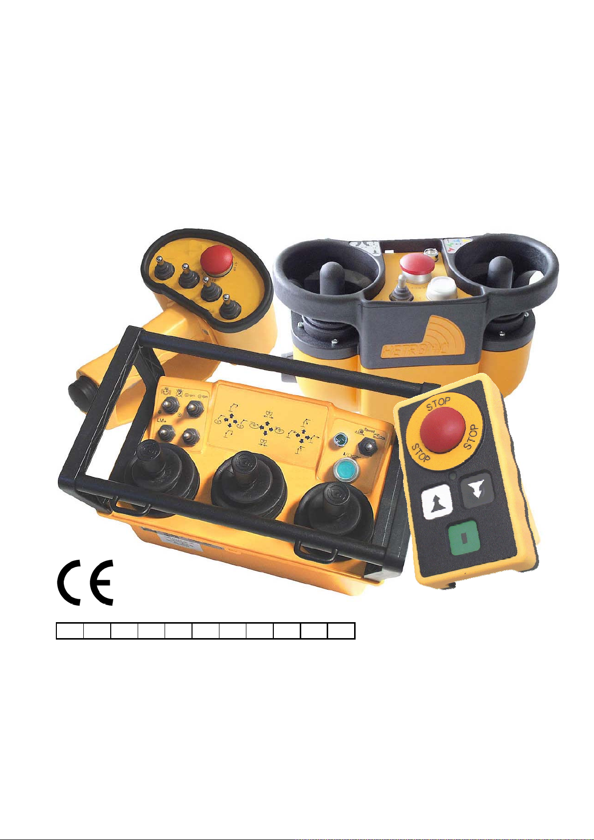
Operating instructions
Installation instructions
for the radio remote control syst ems
of different tr ansmi t ter versions
from
HETRONIC
Please enter the system number here!
Please retain for reference!
Date of publication:
HETRONIC Adalbert – Stifter – Strasse 2 D – 84085 Langquaid
Tel.: +49 (0) 9452/189-0 Fax: +49 (0) 9452/189-201
Page 2

Congratulations on purchasing this high quality safety radio remote control system
from HETRONIC. You have selected a quality product from one of the leading
manufacturers of safety radio remote control systems and therefore can be fully
confident that it reflects state-of-the-art technology.
All rights are reserved, including those relating to photomechanical reproduction and
to recording on electronic media.
The models, illustrations and diagrams contained herein are the property of
HETRONIC and may only be used with our express permission.
Subject to change without notice
Author: J. Mairföls
Version: 30
Date: 03/2006
HETRONIC GmbH
Adalbert-Stifter-Strasse 2
D-84085 Langquaid
Tel.: +49 (0) 9452/189-0
Fax: +49 (0) 9452/189-201
Website: http://www.hetronic.com
e-mail: [email protected]
Page 3

Table of contents
1. Safety
1.2. Safety information and tips
1.3. Sources of risk
1.4. Qualified operators
1.5. Safety precautions in the working area
1.6. Protection devices
1.7. What to do in an emergency
2. Operation
2.1.1. Replacing non-rechargeable/rechargeable batteries
2.1.2. Battery charger and charging the battery
2.2. Control elements
2.3. Operation
2.3.1. Visual checks
2.4. Fault troubleshooting table
2.5. Frequencies and addressing
2.5.1. Frequency allocation for CS434
2.5.2. Frequency allocation for CS458
1.1. Safety of this radio remote control system
2.1. Handling non-rechargeable batteries/rechargeable battery
2.1.3. Battery chargers
2.3.2. Safety checks and starting the radio remote control
system
3. Installation instructions
3.1. Connection information and start-up
3.2. Receiver dimensions
3.2.1. RX-CP housing
3.2.2. HS-1 housing
3.2.3. HS-2 housing
3.2.4. Housing, 250 x 255
3.2.5. Housing, 400 x 250
3.2.6. Housing, 400 x 400
Page 4

4. Maintenance
5. Disposal
6. Technical data
6.1. General
6.2. Rechargeable batteries and battery charger
6.3. Transmitter
6.4. Receiver
6.5. Standard options
7. Appendix A
Page 5
1. Safety
Operating instructions
1.1. Safety of this radio remote control system
This radio remote control system is equipped with both electronic and
mechanical protection devices.
When allocated, coding applies to one transmitter only, meaning that control
commands cannot be received from other transmitters.
This concerns your safety
In the event of incorrect operation or misuse, there is a risk of harm to
- the health of the operator or other persons, and
- the machine and other property.
All persons working with this radio remote control system
- must be both suitably qualified and have been instructed as
required by regulations
- must strictly comply with the contents of these operating
instructions.
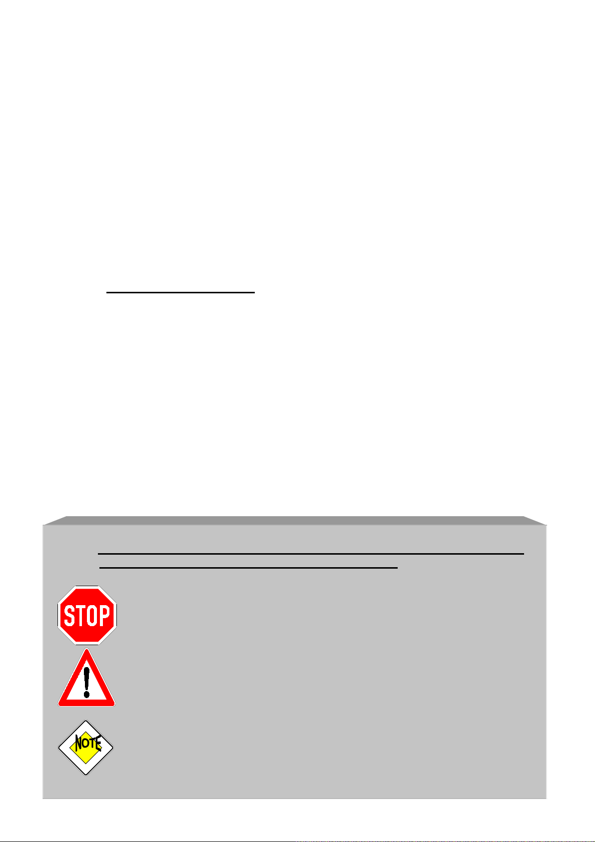
1.2. Safety information and tips
The following symbols are used for warnings and advisory notes in these
operating instructions, with the following meanings:
This symbol is used to warn you of the risk of fatal accidents or serious
injuries. Such risks can arise whenever operating or working
instructions are not strictly followed.
This symbol is used to warn you of the risk of damage to the machine or
to other property if the operating or working instructions are either not
followed or not followed properly. Disregarding these warnings may
void your warranty.
This symbol is intended to draw your attention to particular features or
important information designed to make your work easier.
Page 6

1.3. Sources of risk
The system is designed for permitting machines to be controlled by radio
remote control.
However, since the control commands also are transmitted beyond your range
of vision, and through or around obstacles in the vicinity, you should always:
- Put the transmitter down only in a safe and dry location, switch
the transmitter off and pull the key from the key switch (or if your
transmitter does not have a key switch, remove the rechargeable
battery or the battery compartment).
- Disconnect the power supply before you start any installation,
maintenance or repair work!
- Avoid removing or modifying any safety devices!
1.4. Qualified operators
(Refer to the operating instructions for the machine you intend to
operate with this control system!)
The operator is responsible for ensuring that when the transmitter is put down,
it cannot be used by unauthorized persons. This can be done either by pulling
the key from the key switch, by removing the rechargeable battery or by
storing the transmitter in a locked location.
The owner must:
- provide the operator with these operating instructions
and
- ensure that the operator has read and understood them.
1.5. Safety precautions in the working area
- Ensure that there is no risk of slipping in the work area.
- Before each use of the radio remote control system, check that
nobody is within the working area or swiveling range of your load.
- If a carrying aid is prescribed for your transmitter, this is to be
worn during use.
Either turn the key switch to the off position and pull the key, or
remove the rechargeable battery or the battery compartment from
the receptacle when putting the transmitter down. This will prevent
undesired use or misuse of the transmitter by third parties.
Page 7
1.6. Protection devices
The machine will be stopped:
- If you actuate the red EMERGENCY STOP button or the Stop button
on the control panel of the transmitter
- If the range is exceeded
- If there is receiver or transmitter interference or when the radio signal is
interrupted
- If the rechargeable battery or the battery compartment is removed
- If the rechargeable battery or non-rechargeable batteries is/are run
down
These protection devices:
- are included for the safety of both persons and property, and
- must not be modified, removed or bypassed under any circumstances
or in any way whatsoever!
Additional protection devices (depending on transmitter version):
- Guard rim, guard clip or recessed function buttons. These safety
devices protect against undesired actuation of the control elements,
which in turn prevents unintentional control commands from being
transmitted.
1.7. What to do in an emergency
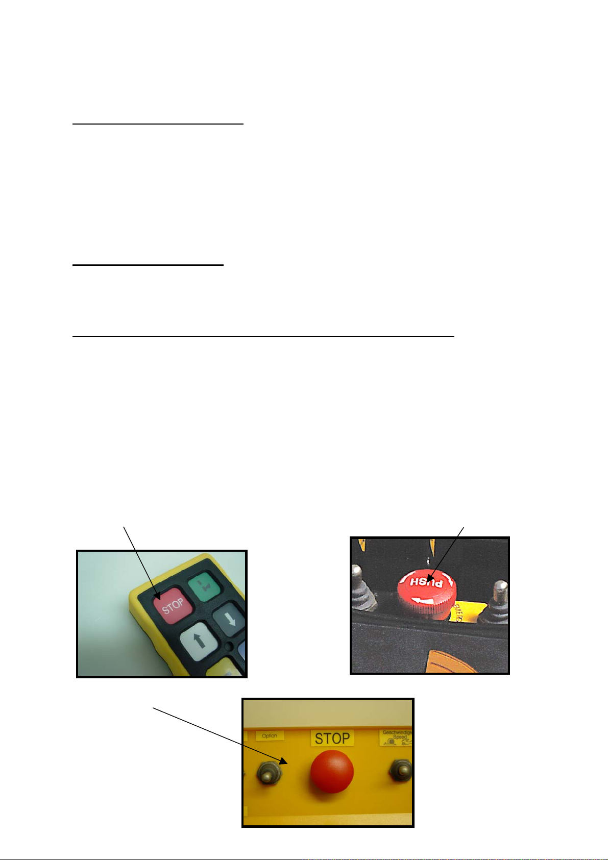
In an emergency, immediately press the red EMERGENCY STOP button
or the other EMERGENCY STOP button on the transmitter control panel.
Then proceed as instructed in the operating instructions for your
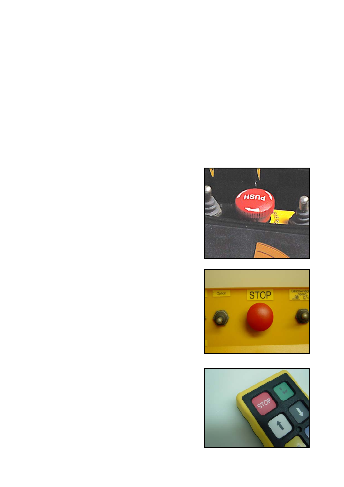
machine. (Figs. 1 - 3)
EMERGENCY STOP button Red EMERGENCY STOP
button Version 1
(Fig. 1) (Fig. 2)
Red EMERGENCY STOP
button
Version 2
(Fig. 3)
Page 8

2. Operation
Have you read and understood the operating instructions, in particular section
1 on safety and protection devices?
You may not
2.1. Handling non-rechargeable/rechargeable
batteries
Depending on the version, HETRONIC radio remote control systems either
come with a battery compartment for two or three 1.5 V alkaline mignon
batteries
or
with a HETRONIC rechargeable battery/battery charger set (12/24 VDC or
115/230 VAC depending on the transmitter type) and two HETRONIC
interchangeable batteries
or
with a VersaPak rechargeable battery/battery charger set (115 V AC or 230 V AC)
with two interchangeable VersaPak penlite batteries rated at 3.6 V each.
If your HETRONIC radio remote control system was
delivered with a battery compartment for alkaline mignon
batteries, never attempt to charge the battery
compartment with the alkaline batteries in a battery
charger!
Alkaline batteries are not capable of recharging; only
batteries specially designed for this purpose can be
recharged!
use the device until you have done so!
Page 9

2.1.1. Replacing rechargeable/non-rechargeable
batteries
Ensure that there is no dirt or grime in the non-rechargeable /
rechargeable battery compartment, as this can lead to breaks in contact.
Only use alkaline batteries. Zinc-carbon batteries are not suited for
powering the transmitter. The transmitter electronics continuously
monitor the battery voltage. When this has dropped below a certain
value, the operating LED on the transmitter begins to flash red, or you
hear an acoustic signal and the system switches off (handheld
transmitter versions excluded).
Proceed as follows:
- Bring the machine to a safe state within 30 seconds (transmitter
switches off after about 30seconds).
- Switch off the transmitter by turning the key switch to position 0 (if your
transmitter has a key switch).
Alkaline mignon batteries:
- Remove the battery compartment with the run down alkaline batteries
from the transmitter.
- Remove the run down alkaline batteries (two or three).
- Place two or three fully charged 1.5 V alkaline batteries in the battery
compartment as depicted on the latter.
- Insert the battery compartment in the battery receptacle of the
transmitter with the contacts first and the open side facing down, or
insert the battery compartment in the battery receptacle of the
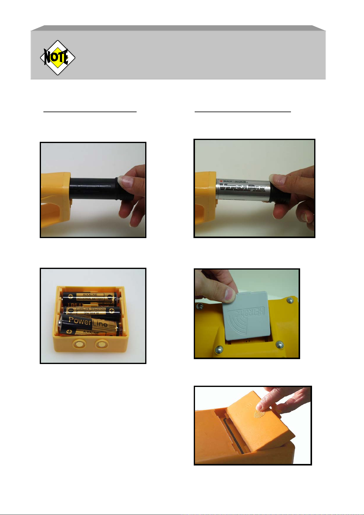
transmitter with the narrower end first (see Figs. 4 and 6).
- Now press the battery compartment until it fully locks into place.
VersaPak rechargeable battery:
- Press the lever at the end of the rechargeable battery compartment until
the battery releases.
- Replace the run down rechargeable battery with a fully charged one.
- Press the end of the rechargeable battery until it fully locks into place
(see Fig. 5).
HETRONIC rechargeable batteries:
- Remove the run down rechargeable battery by pressing the edge lip or
battery cover forward, then pull up and out.
- Take a charged battery and insert it in the designated pockets of the
transmitter battery compartment with both contact points forward
(NOVA) or down (GL) and both guide rails down.
- Then press the rechargeable battery in the direction of the battery
receptacle until the battery fully locks into place (see Figs. 7 and 8).
Page 10
2.1.2. Battery charger and charging the battery
Charging the rechargeable batteries:
- Remove the rechargeable battery as described in section 2.1.1.
- Then place the battery in the charger designed for your particular battery
(see Figs. 9 to 11).
- Ensure that the battery charger is connected to the respective power
supply (power plug, vehicle, etc.).
- Charging should take approximately 3 to 6 hours, depending on the
version. See section 6, “Technical data”, for more information.
Please make sure that you read the operating instructions
provided by the manufacturer for the battery charger prior
to use and that you follow all safety instructions contained
therein. HETRONIC will not accept liability for improper or
negligent use.
Only use genuine HETRONIC parts or parts approved by
HETRONIC. Not doing so introduces the risk of explosion!
Emitted chemicals and flying parts can cause injury.
Battery chargers from HETRONIC have a charge level
recognition feature that automatically switches the charger
to charge retention mode when the batteries are at full
capacity. Always leave one battery in the HETRONIC
battery charger so that you will have a fully recharged
battery in reserve at all times.
To prevent possible damage to VersaPak rechargeable
batteries and the battery charger: Please ensure that
VersaPak batteries do not remain in the battery charger for
more than 24 hours (only applies to VersaPak penlite
rechargeable batteries and the battery charger).
Batteries and rechargeable battery packs are to be treated
as hazardous waste!
Use a specialist disposal company for recycling and
disposal! Defective rechargeable battery packs can also be
disposed of directly through HETRONIC.
Page 11
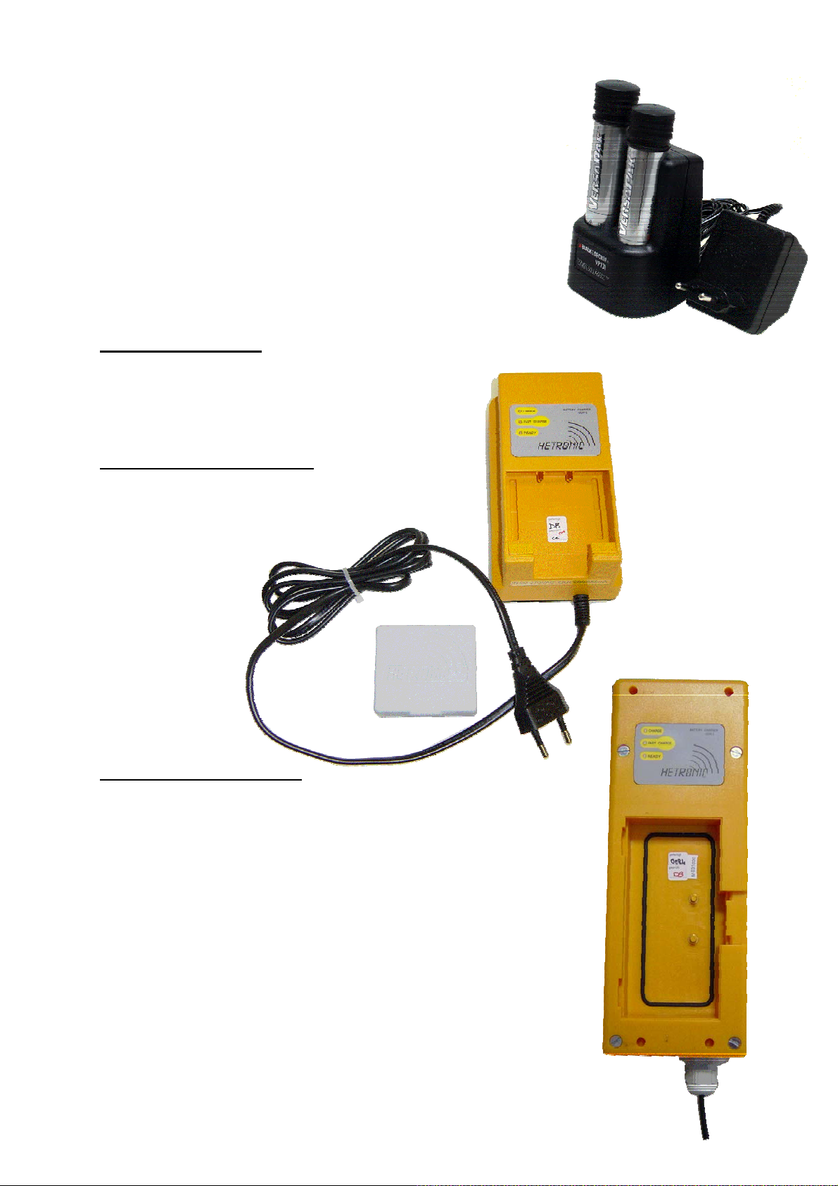
2.1.3. Battery chargers
Battery charger UCH-2-AC or UCH-DC
The battery charger contains a processor to control and regulate
the whole charging process. Depending on the version it is
designed for operating voltages of 10-30 VDC or 90-270 VAC.
After inserting the battery, a yellow LED indicates the charging
process. When the battery is fully charged a green LED lights
up. When you switched to fast charge a red LED lights up
additionally. If no LED is shining after inserting battery
on power at charger the yellow LED is flashing continuously,
the battery is bad.
Version 1, VersaPak
Version 2, HETRONIC MINI
(Fig. 10)
Version 3, HETRONIC GL
(Fig. 9)
(Fig. 11)
Page 12
Your HETRONIC radio remote control system is delivered with
charged rechargeable batteries (optional) or with
non-rechargeable batteries, i.e. the radio remote control system
is ready for immediate use.
Battery compartment: Rechargeable battery:
Version 1 Version 1, VersaPak rechargeable
battery
(Fig. 4) (Fig. 5)
Version 2 Version 2, HETRONIC MINI
(Fig. 6) (Fig. 7)
(Fig. 8)
Version 3, HETRONIC GL
Page 13

2.2. Control elements
Please refer to the transmitter and receiver diagram included with these
operating instructions for the control element arrangement of your radio remote
control system. The diagram forms an integral part of these operating
instructions.
The following is a description of those control elements that are standard on
HETRONIC radio remote control systems.
2.3. Operation
Before you use the system, you must carry out the safety checks described in
sections 2.3.1. and 2.3.2. below.
These safety checks must be carried out at least once each day before you start
using the system or before each change of shift.
A diagram of your transmitter version is included with these operating
instructions. The diagram forms part of the operating instructions. The
arrangement of the control elements and the transmitter labeling will vary
subject to customer requirements, but generally will be the same as the
labeling of the previous controls. The only essential difference, in fact, is
that you will now be able to exert control without the need for cable
connections.
Refer also to the manufacturer's operating instructions for your
machine and the diagram of your transmitter version to familiarize
yourself with the arrangement of the control elements and their
functions!
The section below deals with the radio remote control system’s control elements
and special features.
Risk to life and property!
Check the EMERGENCY STOP function each time
before use as described in the manufacturer’s
manual.
Page 14

2.3.1. Visual checks
Always
- Are all protection devices present and intact?
- Are there any broken parts?
- Are the rubber sleeves and pushbutton caps free of cracks?
Never work with a transmitter that is damaged in any of these ways!
Ensure that such damage is dealt with immediately!
check the transmitter for damage each time before use!
2.3.2. Safety checks and starting the radio remote
control system
- Check the charge state of your transmitter’s power supply (rechargeable
battery, non-rechargeable batteries)
- In the event that your transmitter is equipped with an EMERGENCY STOP
button, ensure that it is not activated. If the button is activated, unlock it (see
pictures 12,13 and 14).
- Now start the machine to be controlled.
- If your transmitter has a green START button, press it or start the
transmitter by turning the key switch. If your transmitter does not have a
green START button, start the machine by pressing one of the function
buttons or the rocker switch.
- Jog mode: The transmitter does not transmit a continuous signal after the
START button or one of the function buttons is pressed, but switches itself
off two seconds afterwards. Thus, keep one of the function buttons
depressed in this mode upon actuating the EMERGENCY STOP button or
the STOP button during a safety check.
Continuous transmission mode: The radio signal and the EMERGENCY
STOP relay remain active until the transmitter is switched off.
- Now press one of the function buttons of the transmitter and keep it
depressed.
Page 15
- Check the EMERGENCY STOP function as described in the
manufacturer's manual, however, instead of pressing the EMERGENCY
STOP button on the machine, press the Emergency Stop button or the
yellow STOP button on the control panel of the transmitter.
- Now press the EMERGENCY STOP button or the yellow STOP button
on the transmitter.
Once you have pressed the EMERGENCY STOP button on the
transmitter, it should no longer be possible to exercise control over
any of the machine’s functions!
- Have you completed the checks and does the EMERGENCY STOP
system function properly?
- Now release the function button and unlock the EMERGENCY STOP
button on the transmitter again.
- After the EMERGENCY STOP button has been unlocked and the
transmitter restarted, the system is ready for operation again.
EMERGENCY STOP button, version 1
Unlock by turning clockwise.
(NOVA transmitters)
(Fig. 12)
EMERGENCY STOP button, version 2
Unlock by pulling up.
(GL, handheld, and GR and TG transmitters)
(Fig. 13)
STOP button
Inching mode only (MINI transmitters)
(Fig. 14)
Page 16
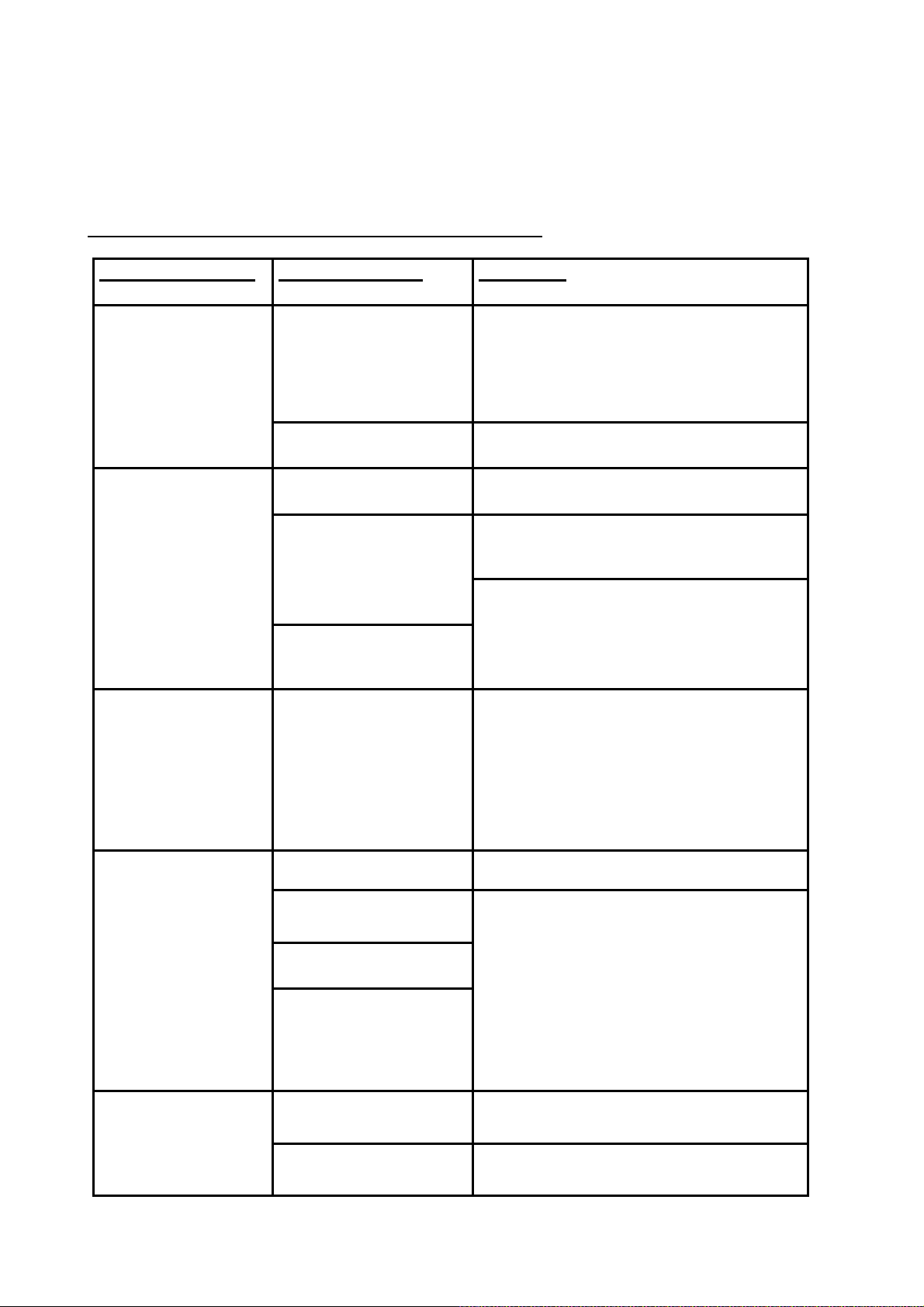
2.4. Fault troubleshooting table
Your radio remote control system has been designed and manufactured using state-of-the-art
technology. Every individual device is subjected to a stringent quality control process at the
manufacturer’s factory before being released for delivery to the customer.
Please check the following points in the event of a fault:
Trouble symptom
Possible causes
Remedies
On/Off function cannot be
actuated or controlled.
No reaction to keying the
transmitter.
Operating time is too short.
Self-test routine
Rechargeable battery/nonrechargeable batteries run down.
Interruption to receiver power supply.
Rechargeable battery or battery
compartment is defective (contact
corrosion).
Batteries are run down.
A non-compatible transmitter and
receiver combination is being used.
Addresses of transmitter and receiver
do not correspond with each other.
Incorrect or run down rechargeable
batteries/non-rechargeable batteries
were inserted.
The transmitter is ready for operation after a 3 second self-test
routine.
Insert charged rechargeable battery or check non-rechargeable
batteries. Switch on the master switch of the machine.
Check connectors.
Measure the power supply of the receiver.
Check to see if the same effect occurs with the second
rechargeable battery or with new batteries.
Check the battery compartment and rechargeable battery
compartment and clean if required. Please contact your dealer.
Check the system number on the stickers of the transmitter and
receiver to see if you are using two compatible devices. The device
numbers correspond to the system address and therefore must be
identical.
Check if the power supply for the charger was switched off, or if the
connection is faulty or loose.
Only use rechargeable batteries approved by HETRONIC.
Only use alkaline batteries.
There is interference with the
transmission of the control
commands to the machine.
Individual functions cannot be
actuated or controlled.
No radio link.
Check to see if there is a large metal
surface located between the
transmitter and receiver.
The range has been exceeded. Please
contact your dealer.
The receiver is located in a steel
cabinet or a vehicle, or is installed
inside the machine to be controlled.
The aerial is inadequate.
A radio remote control system with the
same frequency is being used within
the vicinity.
Break in the control lead between the
machine and the receiver.
Output module in receiver is defective.
Check that a yellow and red LED flash on the receiver. If not,
please contact your dealer.
A projecting aerial must be installed outside the steel cabinet,
vehicle or the machine to be controlled. Try an alternative
frequency setting for the transmitter and receiver. Please contact
your dealer.
Check that the connector plug is properly seated. Check the
connecting cable to the machine. Check the wiring and carry out
cable-based control checks of the individual functions if necessary.
Check that a LED illuminates on the output modules in the receiver
in response to actuating the corresponding function. Please contact
your dealer.
Page 17
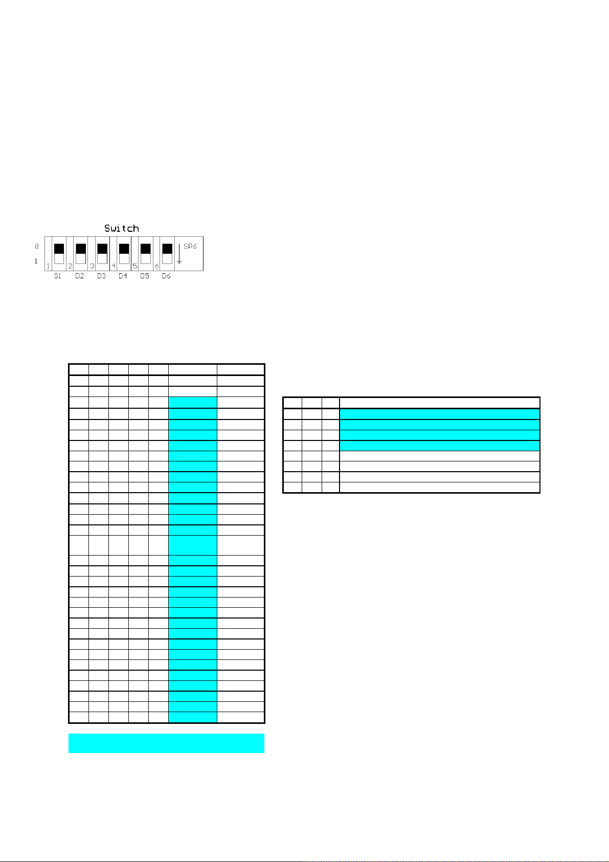
2.5. Frequencies and addressing
Radio remote control systems from HETRONIC include a CS434, CS447 or
CS458 RF module synthesizer (not subject to registration), which incorporates
an RF transmitter module and an RF receiver module.
2.5.1. Frequency allocation for CS434
FREQUENCY ALLOCATION FOR CS434TXN
MANUAL
SETTING
S1 = 0 S1 = 1
D2 = 1 = FCS (Free Channel Search TX), and SCAN-RX
D2 D3 D4 D5 D6 Frequency Channels D3 = 1 = AUTX (Automatic Channel Change TX), and SCAN-RX
0 0 0 0 0 433.1000 2
0 0 0 0 1 433.5500 20 Freq Group for FCS/AUTX/SCAN
0 0 0 1 0 434.0500 40 D4 D5 D6 Channels
0 0 0 1 1 434.0750 41 0 0 0 68, 58, 54, 52, 49, 41
0 0 1 0 0 434.1000 42 0 0 1 67, 59, 55, 53, 47, 44
0 0 1 0 1 434.1250 43 0 1 0 66, 64, 61, 57, 51, 43
0 0 1 1 0 434.1500 44 0 1 1 65, 63, 60, 56, 50, 42
0 0 1 1 1 434.1750 45 1 0 0 38, 32, 28, 18, 10, 8, 5
0 1 0 0 0 434.2000 46 1 0 1 37, 29, 25, 23, 17, 14, 4
0 1 0 0 1 434.2250 47 1 1 0 36, 34, 31, 27, 21, 13, 3
0 1 0 1 0 434.2500 48 1 1 1 35, 33, 30, 26, 20, 12, 2
0 1 0 1 1 434.2750 49
0 1 1 0 0 434.3000 50 If FCS is selected,
0 1 1 0 1 434.3250 51 the module will remember the last frequency that is set and then the
0 1 1 1 0 434.3500 52 frequency change is made by pushing the decrement switch button.
0 1 1 1 1 434.3750 53 FCS on the transmitter module will only work with decrement switch
1 0 0 0 0 434.4000 54
1 0 0 0 1 434.4250 55 In AUTX mode, the TX module will remember the last frequency
1 0 0 1 0 434.4500 56 and then it will au tomatically decrement the chann el ever yt ime
1 0 0 1 1 434.4750 57 it is cycled On-Off-On.
1 0 1 0 0 434.5000 58
1 0 1 0 1 434.5250 59 In both, AUTX and FCS mode, the decrement switch button is
1 0 1 1 0 434.5500 60 always active.
1 0 1 1 1 434.5750 61 Thus, the user can change the frequency by pushing the button.
1 1 0 0 0 434.6000 62
1 1 0 0 1 434.6250 63
1 1 0 1 0 434.6500 64
1 1 0 1 1 434.6750 65
1 1 1 0 0 434.7000 66
1 1 1 0 1 434.7250 67
1 1 1 1 0 434.7500 68
1 1 1 1 1 434.7750 69
Maximum power is 10mW ERP, 100% duty cycle in
Europe
Maximum power is 1mW ERP, 100% duty cycle in
Europe
AUTOMATIC SETTING
button.
Page 18
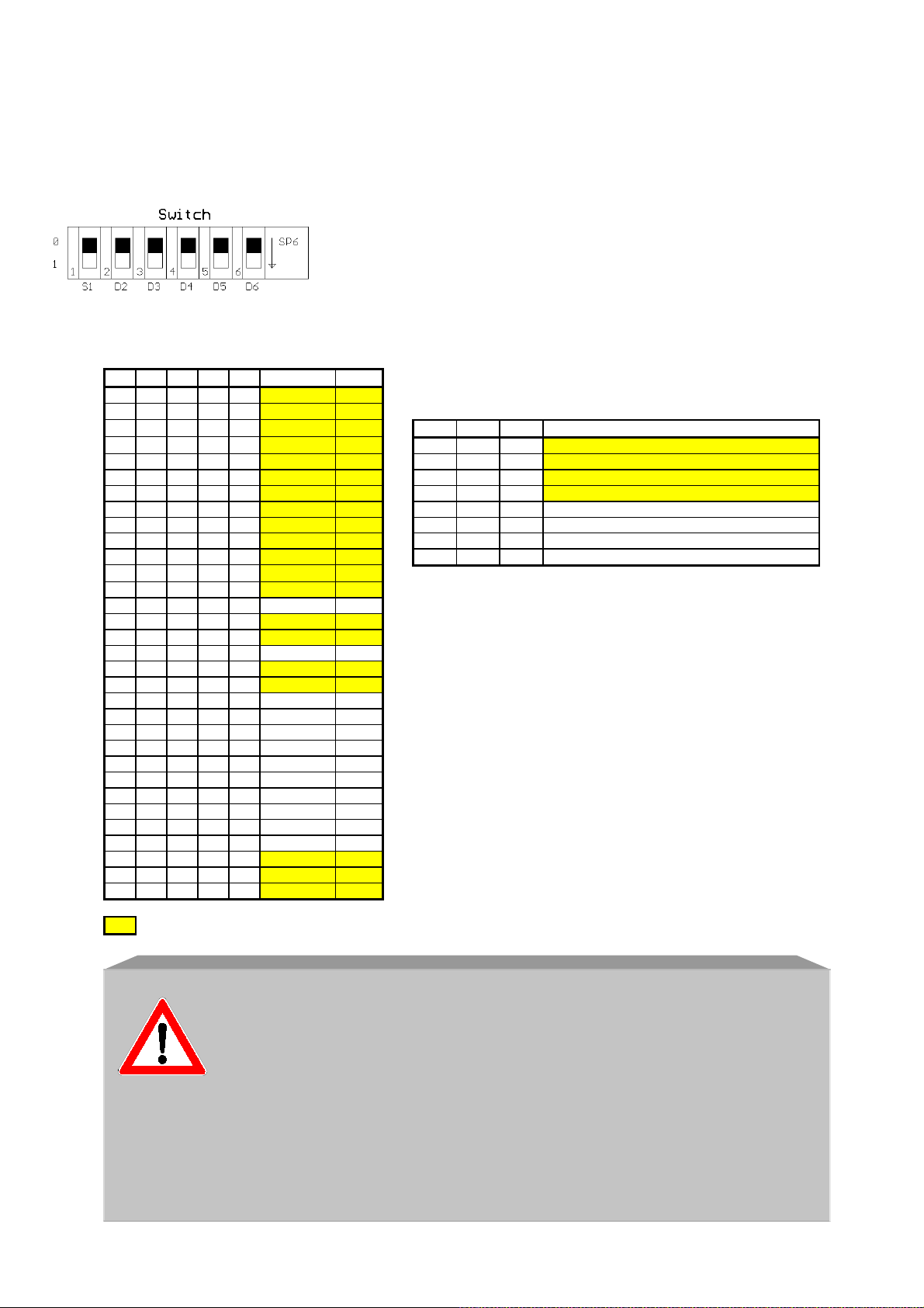
2.5.2. Frequency allocation for CS458
FREQUENCY ALLOCATION FOR CS458TXN
MANUAL
SETTING
S1 = 0 S1 = 1
D2 = 1 = FCS (Free Channel Search TX), and SCAN-RX
D2 D3 D4 D5 D6 Frequency CH D3 = 1 = AUTX (Automatic Channel Change TX), and SCAN-RX
0 0 0 0 0 458.5000 0
0 0 0 0 1 458.5250 1 Freq Group for FCS/AUTX/SCAN
0 0 0 1 0 458.5500 2 D4 D5 D6 Channels
0 0 0 1 1 458.5750 3 0 0 0 18, 15, 10, 3, 1
0 0 1 0 0 458.6000 4 0 0 1 17, 14, 9, 2, 0
0 0 1 0 1 458.6250 5 0 1 0 18, 12, 8, 5, 3
0 0 1 1 0 458.6500 6 0 1 1 17, 11, 7, 4, 2
0 0 1 1 1 458.6750 7 1 0 0 27, 19, 16, 14, 10, 0
0 1 0 0 0 458.7000 8 1 0 1 24, 15, 13, 9, 6, 1
0 1 0 0 1 458.7250 9 1 1 0 26, 18, 12, 8, 5, 3
0 1 0 1 0 458.7500 10 1 1 1 25, 17, 11, 7, 4, 2
0 1 0 1 1 458.7750 11
0 1 1 0 0 458.8000 12 If the FCS mode is selected, the module
0 1 1 0 1 458.8250 13 will check for free channels and transmit if a channel is free.
0 1 1 1 0 458.8500 14 The module also remembers the last channel and transmits in
0 1 1 1 1 458.8750 15 that channel the next time power is on.
1 0 0 0 0 458.9000 16 If all channels are occupied, the module will transmit at the least crowded
1 0 0 0 1 458.9250 17 channel.
1 0 0 1 0 458.9500 18
1 0 0 1 1 458.9750 19 In AUTX mode, the TX module will remember the last frequency
1 0 1 0 0 459.0000 20 and then it will automatically decrement the channel everytime
1 0 1 0 1 459.0250 21 it is cycled On-Off-On.
1 0 1 1 0 459.0500 22
1 0 1 1 1 459.0750 23 In both, AUTX and FCS mode, the decrement switch button is
1 1 0 0 0 459.1000 24 always active.
1 1 0 0 1 459.1250 25 Thus, the user can change the frequency by pushing the button.
1 1 0 1 0 459.1500 26
1 1 0 1 1 459.1750 27
1 1 1 0 0 459.2000 28
1 1 1 0 1 458.5000 0
1 1 1 1 0 458.5250 1
1 1 1 1 1 458.5500 2
UK Channels
AUTOMATIC SETTING
Use of the CS 434 RF module is not subject to registration or
payment of a fee!
The transmitter must never be used without an aerial, as this could
destroy the RF module!
The frequency is preset by HETRONIC in the factory. If you should
experience difficulties with the radio link in your system, please
contact your dealer or HETRONIC’s aftersales service team. The
phone number can be found on the cover page of these operating
instructions.
Page 19
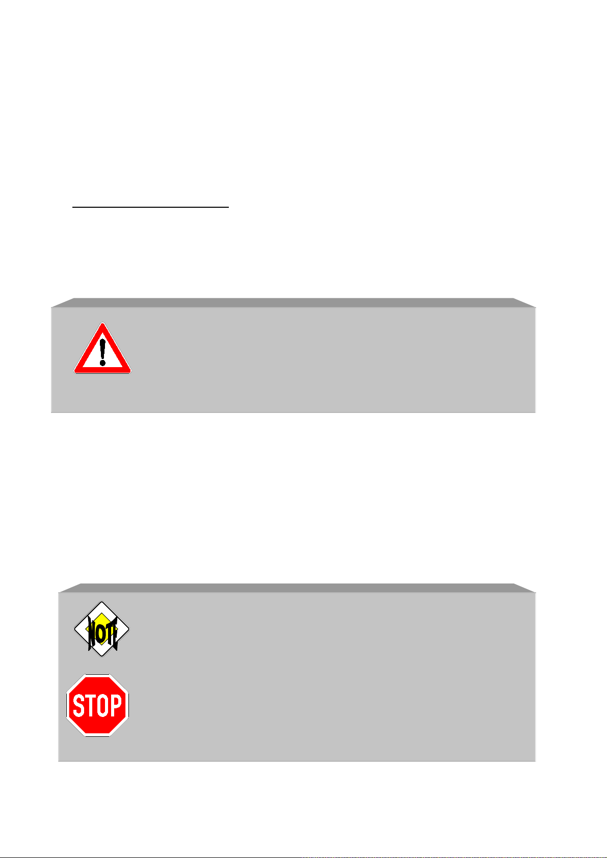
3. Installation instructions
3.1. Connection information and start-up
The machine may only be connected by a qualified expert familiar with the machine
to be operated (see section 4., “Maintenance”).
The following also applies:
- Before starting any work on the switch cabinet or the receiver, switch off
the power supply to the machine to be controlled.
- VDE regulations (German Association of Electrical Engineers), the
regulations of local electricity supply companies, and German UVV
(accident prevention) safety regulations must all be fulfilled.
HETRONIC will not accept liability or provide a guarantee in the
event of personal injury, damage to property and consequential
damage resulting from improper or negligent handling of this
product or from handling that does not comply with the
regulations and standards on which these operating instructions
are based.
Take steps to ensure that the receiver is located in an easily accessible place and is
not installed within the vehicle, the machine to be controlled, a switch cabinet or any
other similar equipment.
If installation in such a location is unavoidable, a projecting aerial must be mounted
with it as well. Suitable projecting aerials can be obtained from your dealer. Please
refer to section 3.3. of these operating instructions for installation information.
Switch off the power supply to the machine before connecting the power
supply unit of the receiver.
Please refer to section 3.2. on the following page for the dimensions of
the receiver and the drilling pattern.
The radio remote control system may only be connected by a
qualified expert familiar with the electrical circuitry of the machine
to be controlled.
Page 20
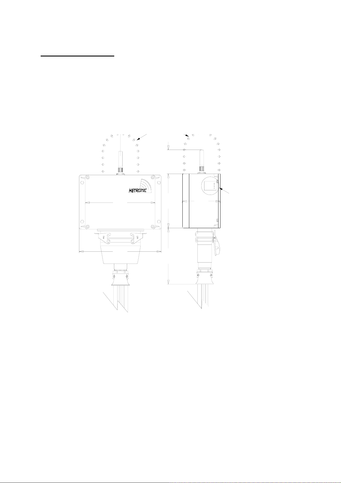
Mounting the receiver:
The receiver should be mounted on the vehicle or machine to be controlled with the
screwed glands or connections underneath. If your receiver is to be installed on a
vehicle or on a mobile machine, you should equip the receiver with four rubber
buffers. These can be obtained from your dealer or direct from the replacement parts
sales division at HETRONIC. The rubber buffers will prevent heavy vibrations being
transferred from the machine to the receiver. A diagram of your transmitter and
receiver version is included with these operating instructions.
ANTENNE muss in vertikaler
AERIAL must point This area must be free of hindrances,
Richtung nach oben zeigen
vertically upwards especially metal surfaces.
Dieser Bereich muss
von Hindernissen frei sein
insbesondere Metallflächen.
71.1 mm
Operation
Normal
Signal
Error
210.5 mm
162 mm
113.5 mm
246.8 mm
167.9 mm
Montieren Sie den Empfänger so, dass das
Diagnos efenst er i mmer si chtbar blei bt.
Mount the receiver in such a way that the
diagnosos window is always visible (only for BMS
(Nur System BMS)
system).
When mounting the receiver, ensure that the aerial is positioned in such a way
that it is minimally shielded by large metallic surfaces.
The receiver has an internal aerial. If it is not possible to mount the receiver in
a favorable position, be sure to order a projecting aerial from your dealer.
Projecting aerials can be ordered with 1.5, 3.0 and 5.0 meter extension lines.
Then mount the aerial in a more favorable position.
3.2. Receiver dimensions
Please refer to the following pages for the receiver dimensions required for
mounting. All receiver types that are offered standard by HETRONIC are
listed. If your receiver type is not listed, you will find a diagram of your receiver
dimensions included with these operating instructions. The diagram forms an
integral part of the operating instructions.
Page 21
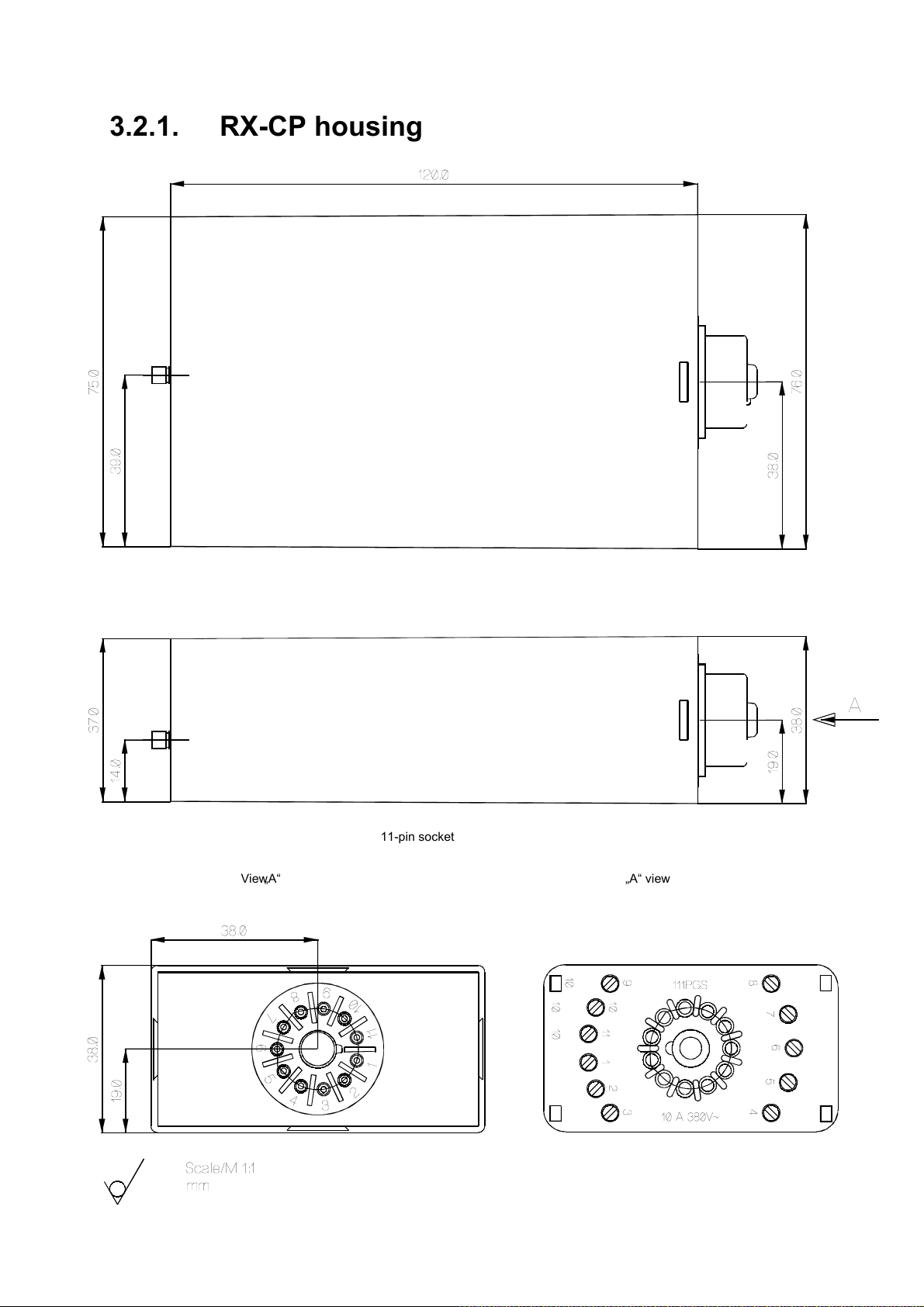
3.2.1. RX-CP housing
View „A“ „A“ view
11-pin socket
11-poliger Sockel / 11-pole socket
Page 22
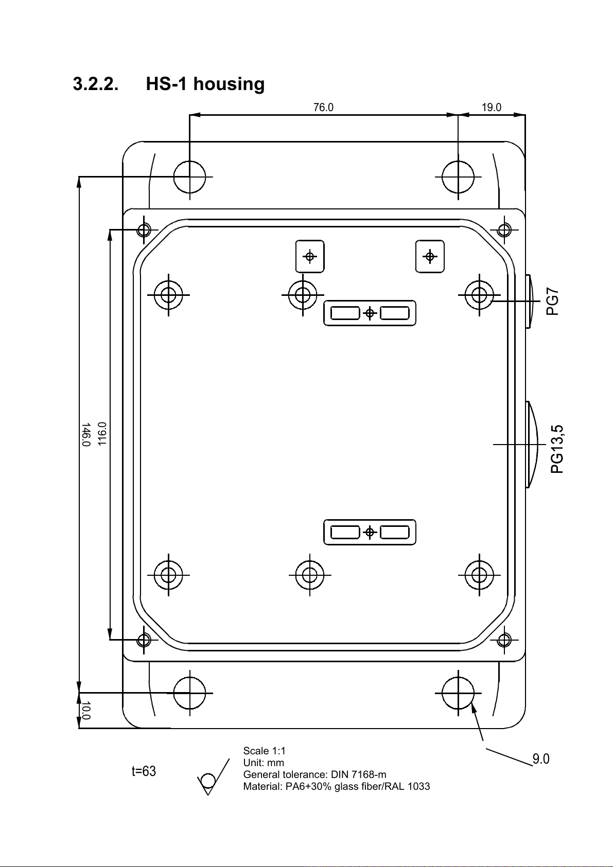
3.2.2. HS-1 housing
76.0 19.0
PG7
146.0 10.0
116.0
PG13,5
PG13,5
t=63
Scale 1:1
Massstab 1:1
Unit: mm
Einheit: mm
General tolerance: DIN 7168-m
Allgemeintoleranz: DIN 7168-m
Material: PA6+30% glass fiber/RAL 1033
Werkstoff: PA6+30% Glasfaser/RAL1033
9.0
Page 23
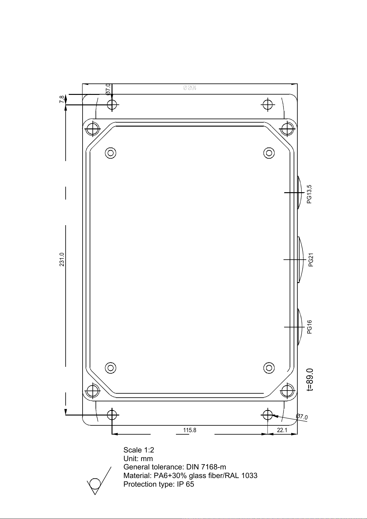
3.2.3. HS-2 housing
Ø7.0
PG13,5
231.0 7.8
PG21
115.8 22.1
Scale 1:2
M 1:2
Unit: mm
Einheit: mm
General tolerance: DIN 7168-m
Allgemeintoleranz: DIN 7168-m
Material: PA6+30% glass fiber/RAL 1033
Werkstoff: PA6+30% Glasfaser/RAL1033
Protection type: IP 65
Schutzart: IP65
PG16
t=89.0
Ø7.0
Page 24
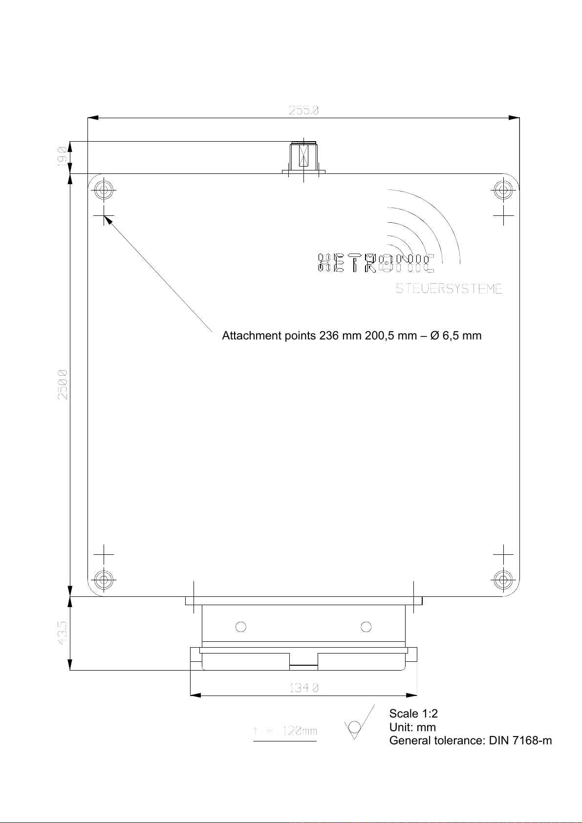
3.2.4. Receiver housing, 250 x 255
Attachment points 236 mm 200,5 mm – Ø 6,5 mm
Scale 1:2
Unit: mm
General tolerance: DIN 7168-m
Scale 1:2
Unit: mm
General tolerance: DIN 7168-m
Page 25
A
p
,
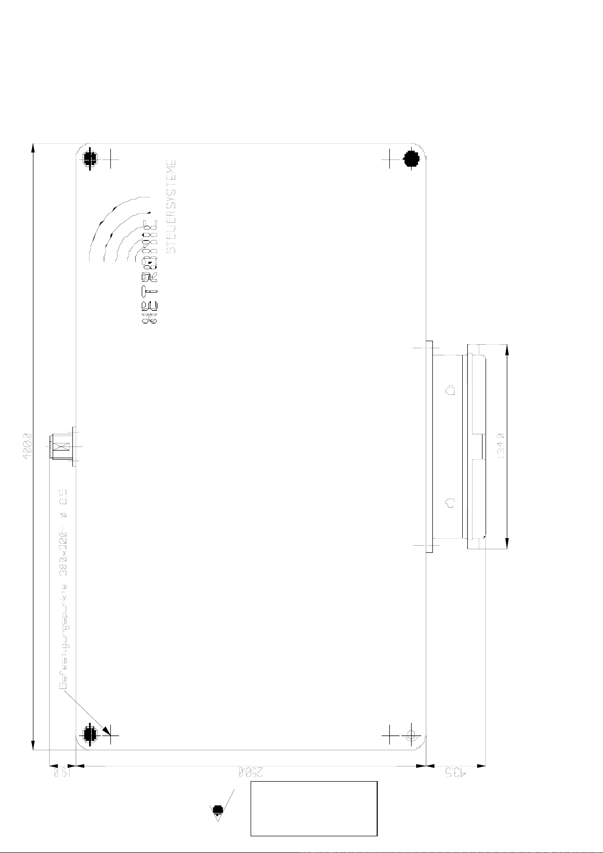
3.2.5. Receiver housing, 400 x 250
5 mm
oints 380x200 mm – Ø 6
ttachment
Scale 1:2
Unit: mm
General tolerance: DIN 7168-m
Page 26
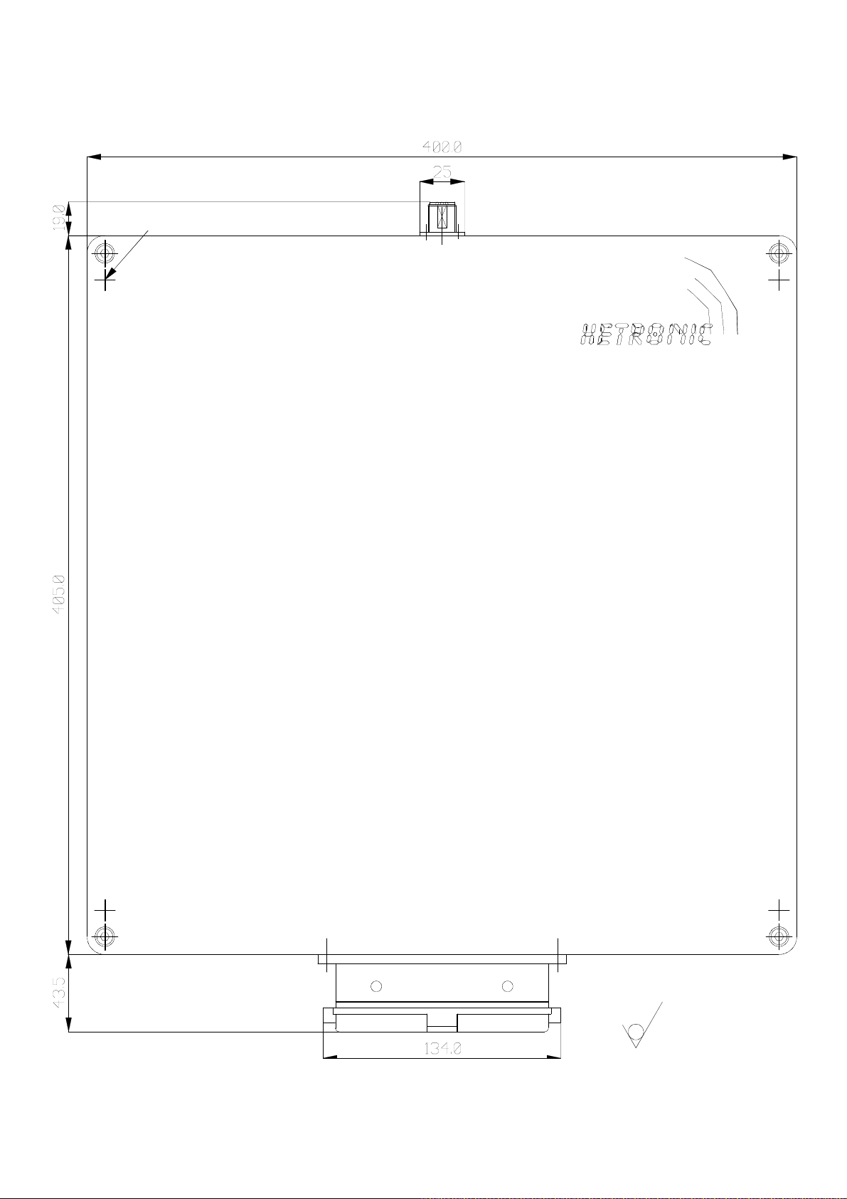
3.2.6. Receiver housing, 400 x 400
A
tachment dimensions 380x355 – Ø 6,5
Maße für Befestigung 380x355- / 6,5
o
STEUERSYSTEME
M 1 :2,5
Unit : mm
M 1:2,5
Einheit: mm
Page 27
4. Maintenance
The employer is responsible for ensuring that devices for the wireless transmission of
control commands are inspected by a qualified expert on a regular basis, and at the latest
once annually.
A qualified expert is someone who has adequate skills and knowledge
in the field of wireless transmission of commands, based on relevant
technical training and experience, and is familiar with applicable
national industrial safety regulations, safety standards, guidelines and
generally approved technical practice (including DIN standards, VDE
standards, and technical standards of other member states of the
European Union or other states party to the convention on the
European Economic Area), to the extent that they can assess the
operating safety of devices for the wireless transmission of control
commands.
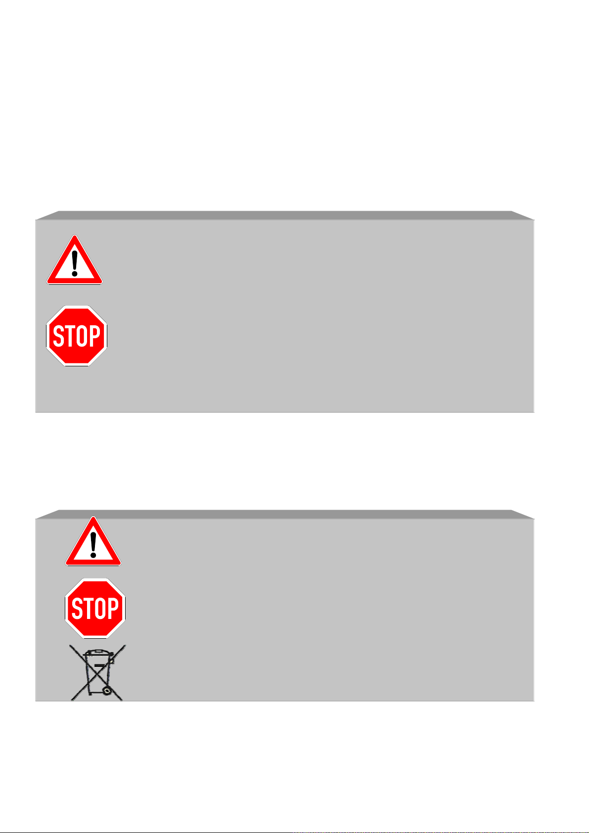
Do not pollute the environment!
5. Disposal
Electronic devices and their components are
hazardous waste!
This applies particularly to rechargeable battery
packs!
Use a specialist disposal company for recycling and
disposal!
Defective rechargeable battery packs also can be
disposed of directly through HETRONIC!
Page 28

6. Technical data
6.1. General:
Frequency range: 400 - 470 MHz
Other frequency ranges available on request
RF synthesizer: Microprocessor-controlled PLL synthesizer with
32 selectable frequencies
RF output: <10 mW standard
Higher transmitter outputs available on request
RF certifications: Certified for frequency ranges subject to approval
and freely assignable frequency ranges in over
40 states
Modulation: FM - narrow bandwidth
Bandwidth: 12.5 kHz/25 kHz according to the system
Range: Approx. 100 meters (with standard aerial)
Approx. 200 meters (with special aerial)
Addressing: 20-bit (over 999,999 individual options)
Temperature range: -25 °C - +70 °C (-18 °F - +160 °F)
Resistance to moisture: 0 - 97 % max. (applies only for
condensation)
Response time: Approx. 55 ms
Baud rate: 2,400/4,800 bps
Main components: Surface mounting, modular construction
Diagnosis: Status displays for RF communication;
operating voltage displays for transmitter and
receiver; undervoltage display
Certificates: CE, TÜV, ISO 9001 to name a few
6.2. Rechargeable batteries and battery charger:
Operating voltage: 9 - 30 VDC or 110/230 VAC
Charging time: Approx. < 4 hours
Service life: Approx. 900 charges
Type: NiCd or NiMh (depending on version)
Capacity: 600 mAh/1,200 mAh (depending on version)
Contacts: Gold-plated, self-cleaning contacts
6.3. Transmitter:
Type: Ergonomically-shaped housing
Housing material: Fiberglass-based polyamid with 30% glass fibre
rate, according to the system
Other materials available upon request
Protection class: IP 65
Weight: Less than 2.00 kg (including non-rechargeable
batteries or rechargeable battery), according to
the system
Aerial: Internal
Non-rechargeable or rechargeable
battery housing: Electrically separated with gold-plated, self-
cleaning contacts
Page 29

Operating time: 14 - 20 hours (continuous operation), according to
the system
Pushbuttons: One or two-stage
Master switch/joystick: All master switches have an automatic reset
function, multiple-steps and proportional, are
moisture resistant and ergonomically designed
6.4. Receiver:
Housing material: Fiberglass-based polyamid with 30% glass fibre
rate, according to the system
Other materials available upon request
Connection: Via moisture resistant connecting plug
Protection class: IP 65
Operating voltage: 9 - 30 VDC, 48/110/220 VAC
Weight: < 7.2 kg
Current consumption: < 0.8 A
Aerial: External aerial, with moisture resistant
connection, partly internal
Digital outputs: Fail-safe and self-monitoring
EMERGENCY/STOP circuit. All relay outputs
275 VAC/8A
Proportional resolution: 8-bit (256 increments per function)
Built-in ramp function selectable
Proportional outputs: PWM signal with selectable dither frequency and
current range
Linear output voltage
Proportional functions set via the transmitter (with
quick set properties) or via potentiometer
Multiple speed ranges selectable
All proportional functions can be set with initial
and final speeds
Serial interfaces - RS232, RS458, CAN bus,
Profibus
6.5. Standard options:
Proportional or digital feedback with or without
display, 45° inclination sensor switch with
configurable time delay in transmitter, dead man’s
master switch, interlocking of individual functions,
mechanical dead man, optical and acoustic
undervoltage display 10 minutes in advance, one
transmitter for multiple receivers, tandem
operation, replacement transmitter, radio remote
controls for explosion-protected areas
Page 30
Page 31
Page 32

7 Appendix A
Installation and safety test declaration
This form must be completed and signed by the person responsible for
undertaking installation of the system.
HETRONIC will not accept liability for the correctness of the installation
of the radio remote control system. As the operator, you have
responsibility for ensuring that the radio remote control system and the
machine have been properly coordinated with each other and tested,
and that all relevant safety provisions are maintained (see section 2).
Intended use!
Machine data: Manufacturer: .............................................
Type description: .............................................
Serial number: .............................................
Year of manufacture: .............................................
Radio remote control system:
Manufacturer: HETRONIC GmbH
Type description: .............................................
….........................................
ID number: ........................................................
I/We have carried out the installation, start-up and safety checks for the
radio remote control system on the above-mentioned machine.
In doing so and in this respect, the latest standards and regulations
applicable to this type of machine have been maintained.
Location/address: ...................................................................................
Date: .......................................................................................................
Company: ...............................................................................................
................................................................................................................
................................................................................................................
................................................................................................................
................................................................................................................
Name of person responsible: .................................................................
Signature: ..............................................................................................
 Loading...