

Hestan GRFR24, GFDSR241 Installation Manual

INDOOR / OUTDOOR
UNDERCOUNTER REFRIGERATION
Refrigerators & Freezers
Installation Manual
EN
DANGER
DANGER
NOTICE
TABLE OF CONTENTS
2 SAFETY DEFINITIONS
3 MODEL NUMBERS
4 RATING LABEL
4 REGULATORY/CODE REQUIREMENTS
4 SAFETY
6 CABINET INSTALLATION
10 DOOR INFORMATION
12 DISPOSAL
READ THESE INSTRUCTIONS CAREFULLY AND COMPLETELY
BEFORE INSTALLING OR USING YOUR APPLIANCE TO REDUCE
THE RISK OF FIRE, SHOCK HAZARD, OR OTHER INJURY. KEEP
THIS MANUAL FOR FUTURE REFERENCE.
IMPORTANT! IMPORTANT! Read and understand all information in this manual before
attempting the installation. All plumbing and electrical work must be
performed by a qualified technician and conform to all applicable state and
local codes.
INSTALLER: LEAVE THIS MANUAL WITH THE OWNER OF THE APPLIANCE.
HOMEOWNER: RETAIN THIS MANUAL FOR FUTURE REFERENCE.
SAFETY DEFINITIONS
THIS INDICATES A HAZARD THAT WILL RESULT IN SERIOUS
INJURY OR DEATH IF PRECAUTIONS ARE NOT FOLLOWED.
THIS INDICATES A HAZARD THAT MAY RESULT IN SERIOUS
INJURY OR DEATH IF PRECAUTIONS ARE NOT FOLLOWED.
THIS INDICATES A HAZARD WHERE MINOR INJURY
OR PRODUCT OR PROPERTY DAMAGE MAY OCCUR IF
PRECAUTIONS ARE NOT FOLLOWED.
THIS INDICATES THAT PRODUCT OR PROPERTY DAMAGE MAY
OCCUR IF PRECAUTIONS ARE NOT FOLLOWED.
RISK OF FIRE OR EXPLOSION - FLAMMABLE REFRIGERANT USED. Consult
repair manual/owners guide before attempting to service this product. All
safety precautions must be followed. To be repaired by trained service personnel only. Use caution
when handling, moving and using the product to avoid damaging the refrigerant tubing or increasing
the risk of a leak.
2
All service work shall be performed by factory authorized service personnel and
all component parts shall be replaced with like components to minimize the risk
of possible ignition due to incorrect parts or improper service.
If service is necessary, repair work must be performed by a Hestan authorized
servicer. Work done by unqualified individuals could potentially be dangerous
and will void the warranty.
©2021 Hestan Commercial Corporation
SAFETY
NOTICE
All models covered in this manual are manufactured using refrigerant R600a (Isobutane). R600a is
a hydrocarbon. This refrigerant is flammable and is only allowed for use in appliances which fulfill
the requirements of UL/IEC 60335-1 and UL/IEC 60335-2-24 (To cover potential risk originated from
the use of flammable refrigerants). Consequently, R600a is only allowed to be used in refrigerating
appliances which are designed for this refrigerant and fulfill the above-mentioned standard.
• R600a is heavier than air. The concentration will always be highest at the floor level.
• The explosion limits are as follows:
o Lower Limit: 1.8% by volume
o Upper Limit: 8.4% by volume
o Ignition Temperature: 860ºF [460°C]
DEFINITIIONS
This product contains blown foam insulation using blowing agent R-611 (Methyl
Formate). The foam in this product does not contain HFC’s, CFC’s, or HCFC’s.
(continued)
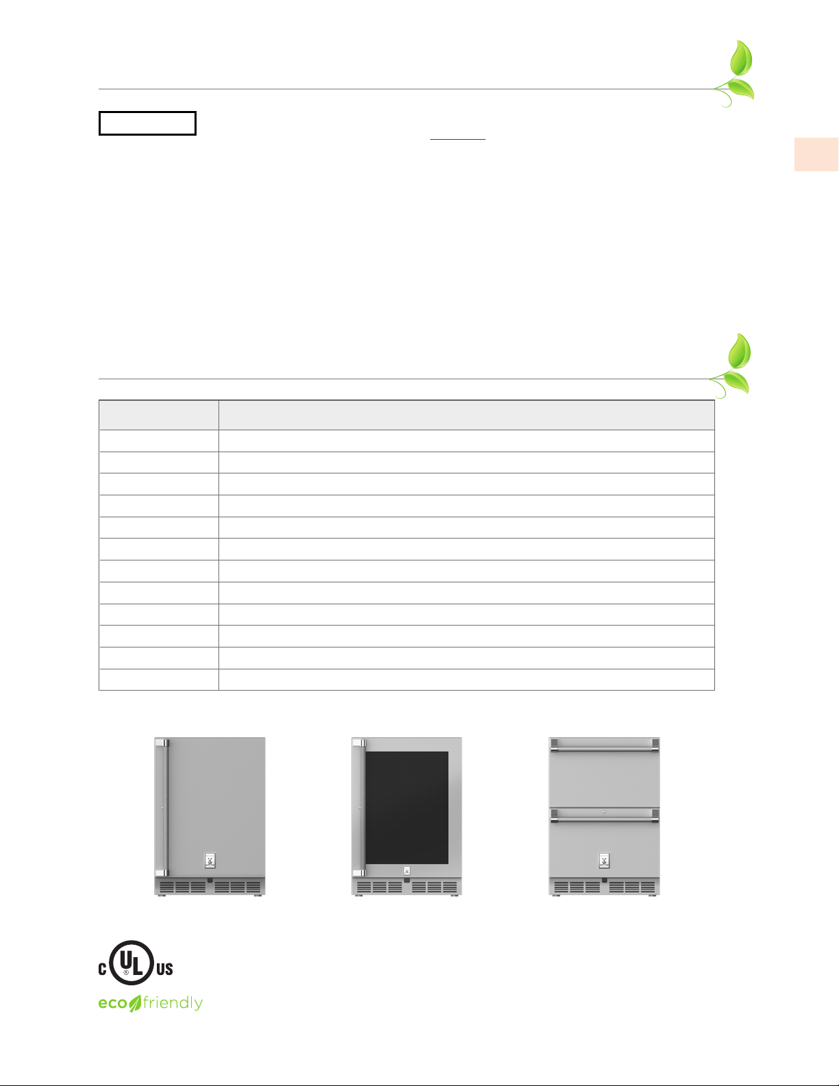
MODEL NUMBERS
Model No. Description
GRS_24 INDOOR / OUTDOOR REFRIGERATOR, SOLID DOOR, 24”
GRS_24-XX INDOOR / OUTDOOR REFRIGERATOR, SOLID DOOR, COLOR, 24”
GRG_24 INDOOR / OUTDOOR REFRIGERATOR, GLASS DOOR, 24”
GRG_24-XX INDOOR / OUTDOOR REFRIGERATOR, GLASS DOOR, COLOR, 24”
GRR24 INDOOR / OUTDOOR REFRIGERATOR DRAWERS, 24”
GRR24-XX INDOOR / OUTDOOR REFRIGERATOR DRAWERS, COLOR, 24”
GRFR24 INDOOR / OUTDOOR REFRIGERATOR DRAWER AND FREEZER DRAWER, 24”
GRFR24-XX INDOOR / OUTDOOR REFRIGERATOR DRAWER AND FREEZER DRAWER, COLOR, 24”
GRWS_24 INDOOR / OUTDOOR DUAL ZONE REFRIGERATOR WITH WINE, SOLID DOOR, 24”
GRWS_24-XX INDOOR / OUTDOOR DUAL ZONE REFRIGERATOR WITH WINE, SOLID DOOR, COLOR, 24”
GRWG_24 INDOOR / OUTDOOR DUAL ZONE REFRIGERATOR WITH WINE, GLASS DOOR, 24”
GRWG_24-XX INDOOR / OUTDOOR DUAL ZONE REFRIGERATOR WITH WINE, GLASS DOOR, COLOR, 24”
EN
GRSR24 shown
R600a Refrigerant
_ = Right (R) or Left (L) Hinged Model
GRR24 shownGRWGR24 shown
©2021 Hestan Commercial Corporation
3
RATING LABEL
DANGER
DANGER
The rating label contains important information about your Hestan appliance such as the model and
serial number, and refrigerant information if service is required.
EN
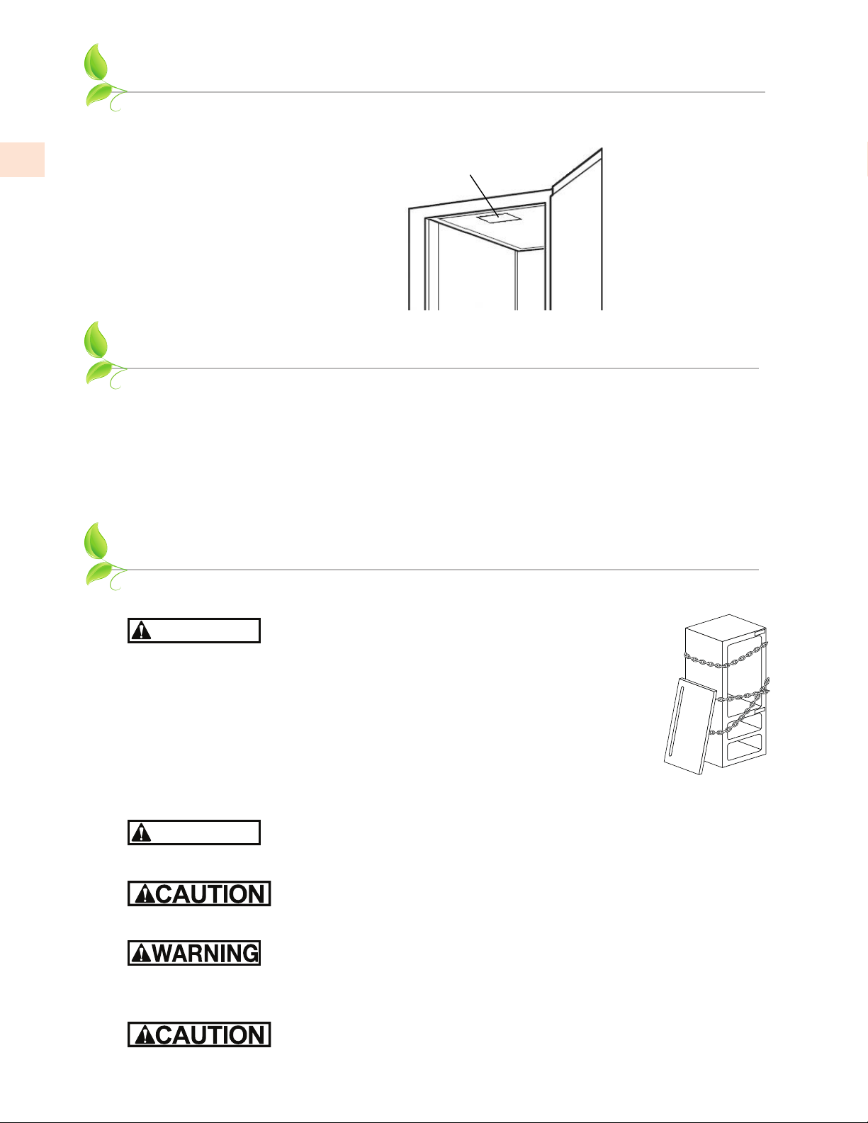
RATING LABEL
The rating label is attached to
the inside top of the cabinet.
REGULATORY / CODE REQUIREMENTS
Installation of this appliance must be made in accordance with local codes. In the absence of local
codes, this unit should be installed in accordance with the National Electrical Code and local codes.
This appliance must be electrically grounded in accordance with local codes or in the absence of
local codes with the National Electrical Code
C22.1
.
ANSI/NFPA 70
, or Canadian Electrical code
CSA
SAFETY
CHILD SAFETYCHILD SAFETY
Risk of child entrapment. Before you throw away your old
refrigerator or freezer:
• Take off the doors.
• Leave the shelves in place so that children may not easily climb inside.
NEVER allow children to play inside the appliance.
PRIOR TO INSTALLATIONPRIOR TO INSTALLATION
Carefully inspect cabinet for hidden damage. If damage is discovered, file your
claim immediately with the transport company. Hestan is not responsible for
damage in transit. Remove any packaging materials before operating.
RISK OF FIRE OR EXPLOSION - FLAMMABLE REFRIGERANT USED.
Use caution when handling, moving and using the product to avoid damaging
the refrigerant tubing or increasing the risk of a leak.
When moving the unit, be sure to protect finished flooring with appropriate
material to avoid damage from moving the unit. Do not lift unit by drawer,
shelving or door handles, as damage to the unit could occur if not moved as instructed.
To prevent personal injury, a minimum of two people are required to lift the
unit. Larger units may require additional personnel.
Before moving the unit, secure the door shut with tape to prevent door from swinging open while
being moved. Carefully move unit to installation site and place in front of opening.
4
©2021 Hestan Commercial Corporation
If unit has been laid on its back or sides, place unit upright and allow a
minimum of 24 hours before connecting power.

DANGER
NOTICE
DANGER
SAFETY
(continued)
PLUMBINGPLUMBING
No plumbing connections are required. Condensate from the cooling coil is automatically evaporated
through a condensate pan located in the condensing section of the unit.
ELECTRICAL SHOCK HAZARDELECTRICAL SHOCK HAZARD
Disconnect power before installing or servicing appliance. Failure to do so can result in death or
electrical shock.
ELECTRICAL GROUNDINGELECTRICAL GROUNDING
• This appliance must be grounded. Grounding reduces the risk of electric
shock in the event of a short circuit.
• DO NOT ground to a gas pipe.
• DO NOT use an extension cord with this appliance.
• DO NOT have a fuse in the NEUTRAL or GROUNDING circuit. A fuse in
the NEUTRAL or GROUNDING circuit could result in an electrical shock.
ELECTRICAL SUPPLYELECTRICAL SUPPLY
A 115 volt AC, 60 Hz, 15 Amp circuit breaker and electrical supply is required. A Ground Fault Circuit
Interrupter (GFCI) protected circuit must be used when installed outdoors.
EN
This appliance is NOT designed for installation in manufactured (mobile) homes or recreational park
trailers.
All units are provided with a 5 ft [1.5 m] cord with three-prong grounding plug. It is imperative that
this plug be connected to a properly grounded three-prong receptacle. If the receptacle is not the
proper grounding type, contact an electrician. The receptacle must be flush or recessed into the wall
surface behind the unit.
• Never remove the grounding prong from this plug.
• Never use a 2-prong adapter.
• If a 2-prong receptacle is encountered, or a longer power cord is required, contract a qualified
electrician to have it replaced in accordance with applicable electrical codes.
Inspect the electrical cord and plug for damage prior to energizing the unit to
avoid potential electric shock.
The unit must NOT be totally enclosed or damage may occur. Air circulation must not
be restricted. The condenser at the cabinet front must be provided with a minimum of
2” [5 cm] air space. Be sure to provide access so the front cover can be removed to clean the condenser.
Do not attempt to operate the equipment on any power source / voltage other
than that listed on the Electrical Specification Plate attached to the unit.
Do not store flammable liquids (i.e. Gasoline or Lighter Fluid) or vapors near the
appliance to avoid a fire.
ADDITIONAL GENERAL INFORMATIONADDITIONAL GENERAL INFORMATION
All electrical instructions assume the outlet is located 4 - 10” [10 - 25 cm] above the floor surface.
Floor must be level in the area of installation. Leg levelers are used for fine-tune adjustment only and
should not be used to compensate for floor differences exceeding 1/2” [13 mm].
©2021 Hestan Commercial Corporation
5
EN
DANGER
NOTICE
CABINET INSTALLATION
RISK OF FIRE OR EXPLOSION - FLAMMABLE REFRIGERANT USED.
Use caution when handling, moving and using the product to avoid damaging
the refrigerant tubing or increasing the risk of a leak.
CASTER KIT (OPTIONAL)CASTER KIT (OPTIONAL)
A Caster Kit (AGCK24) is available for Hestan undercounter refrigeration models. Refer to the
instructions supplied with the caster kit for proper installation.
Note: Installation of the kit adds 3.75” [9.5 cm] to overall height of the unit.
ANTI-TIP BRACKETSANTI-TIP BRACKETS
Unit may tip forward if loaded racks/shelves are all pulled out at the same time. To prevent tipping,
and to provide stable installation, the unit must be secured in place with the anti-tip brackets
supplied with the unit. The anti-tip brackets, when properly installed, should secure the rear legs/
glides to the mounting surface and prevent the unit from tipping forward.
Anti-tip brackets are only used for stationary cabinets and should not be installed on
cabinets with accessory casters.
If installing on a concrete floor, concrete fasteners are required and not included with the anti-tip kit.
Some installation sites may require modifications to provide a secure surface for attaching the
brackets.
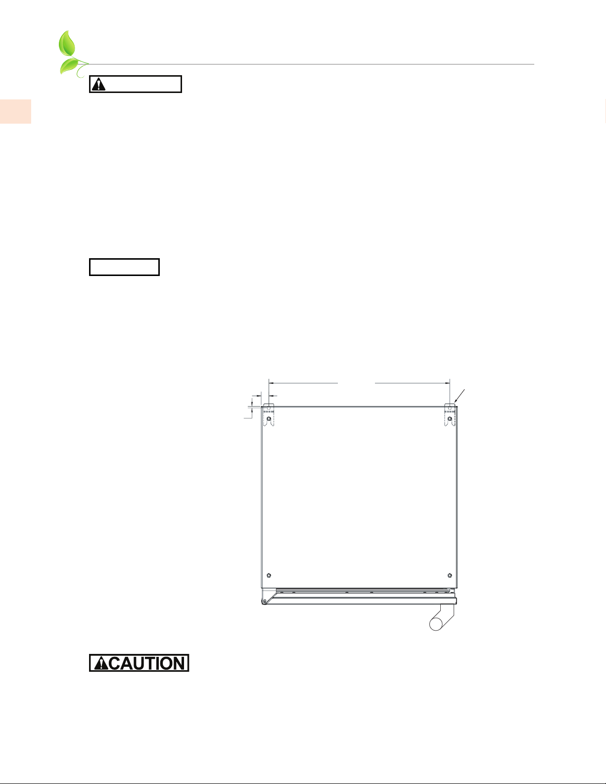
A set of anti-tip brackets is supplied with the unit. These brackets should be attached to the floor at
the rear of the unit. Each bracket must be located to engage the rear legs when the cabinet is pushed
back into position. Refer to Figure 1 (shown below) for anti-tip bracket mounting locations.
3
22-
15
⁄16”
⁄16”
BRACKETS
3
⁄16”
PREPARING THE SPACEPREPARING THE SPACE
If the unit is to be installed under a countertop, it is recommended that the countertop be supported
by a structure other than the unit itself to prevent damage to the unit.
Figure 1. 24” Anti-Tip Kit
Make sure the floor under the unit is level with the surrounding finished floor. Protect a finished
floor with plywood, cardboard, or some other suitable material before moving the unit into place.
Failure to do this may result in damage to the floor.
6
©2021 Hestan Commercial Corporation
CABINET INSTALLATION
NOTICE
when fully extended.
(continued)
To assure maximum performance, fresh air must be allowed to circulate through the machinery
compartment. Do not place anything in front of the unit that would obstruct air flow at these
front grilles. Do not place the unit in an unventilated small room.
Cabinet should be leveled front to back, then side to side.
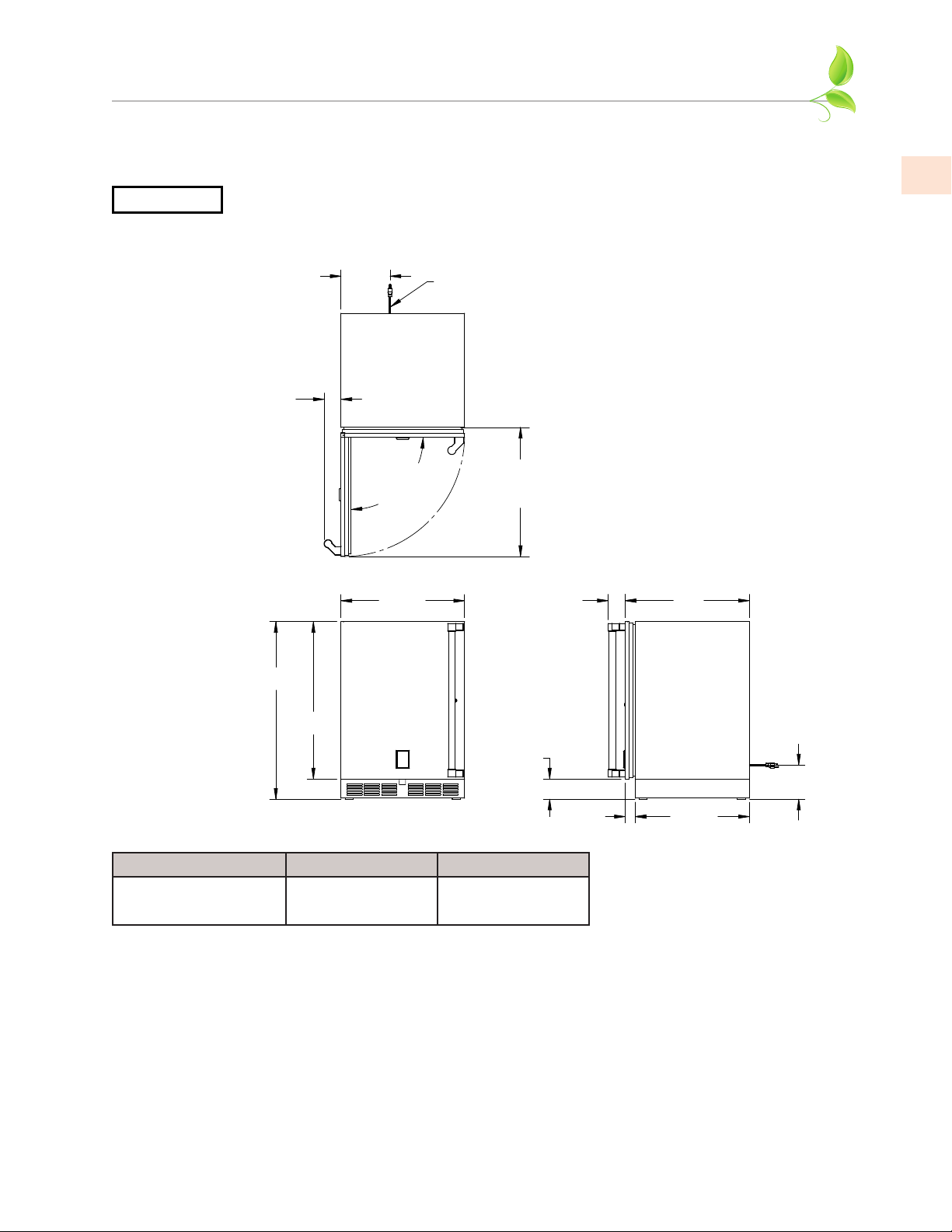
1. Make sure the space opening is correctly sized for the unit. See typical appliance dimensions
below, and the chart below for finished rough opening requirements:
11”
POWER CORD
5 FT. LONG
TYPICAL APPLIANCE
DIMENSIONS
EN
1
3-
⁄
” MIN. CLEARANCE FROM A
4
CORNER TO ACHIEVE 90° SWING
5
*34-
- Leg levelers can add
*
3/4” to these dimensions
CUTOUT DIMENSIONS:
3
⁄
” H - 24” W - 24” D
34-
8
90° SWING
REQUIRED FOR
PULL-OUT SHELF
CLEARANCE
7
23-
/8”
⁄
”
16
3
30-
⁄
”
8
15
⁄
”
24-
*3-
16
3-
15
⁄
”
16
MIN. CLEARANCE
FOR DOOR SWING
5
⁄
”
16
15
1-
⁄
”
16
24”
22-
5
*6-
⁄
”
8
1
⁄
”
16
HEIGHT WIDTH DEPTH
34-3/8” [87.3 cm] min.
35-1/2” [90.2 cm] max.
24” [61 cm] 24” [61 cm]
2. Check that the following are level and square:
• Front and interior opening
• Installation opening and floor surface
• Countertop bottom front edge
NOTE: For a door to open properly, the door must open a minimum of 90°. Use a minimum 3”
[7.6 cm] filler in corner installations to assure a full 90° opening. Allow 25” [64 cm] clearance in
front of unit for full door swing and shelf/drawer pull out.
NOTE: The floor under the unit must be at the same level as the surrounding finished floor.
©2021 Hestan Commercial Corporation
7
EN
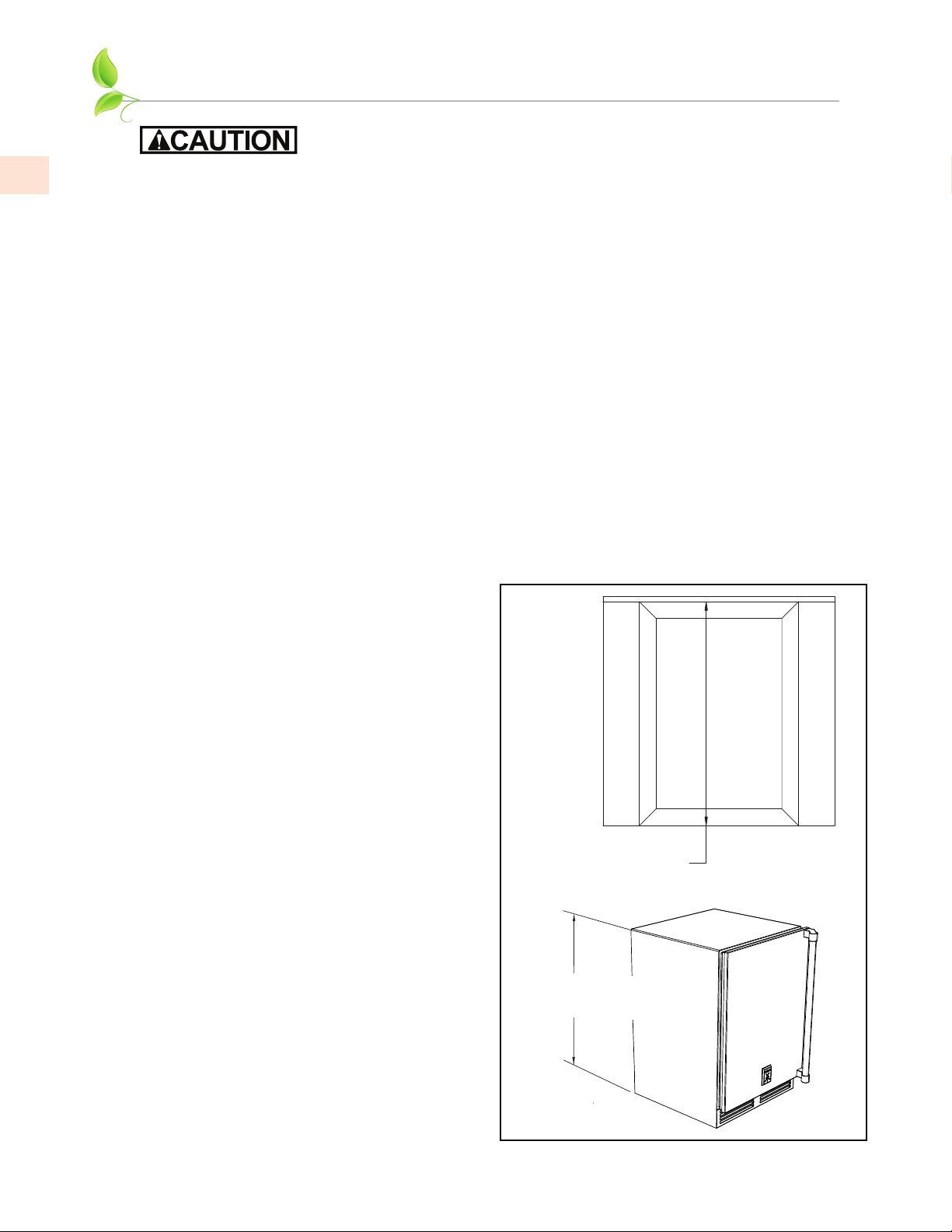
Figure 2. Leveling the Unit
CABINET INSTALLATION
To prevent possible damage to the countertop, do not place heavy objects on
countertop directly over unit.
(continued)
INSTALLING THE UNIT INTO THE SPACEINSTALLING THE UNIT INTO THE SPACE
1. Plug the unit into the 15 amp grounded electrical outlet located within the installation opening.
With power applied to the unit, check that the lighting and cooling functions operate properly.
Turn off the power to the wall outlet at the circuit breaker.
2. With all surfaces in the installation opening square and level, refer to Figure 2 below and perform
the following steps to level the unit:
• At the front of the opening, measure from the floor to the bottom of the front edge of the
countertop.
• Measure from the floor surface to the top of the unit at the rear corners.
• Adjust the unit legs so these two measurements are equal. Using an adjustable wrench or
pliers, turn legs clockwise to lower the unit or counterclockwise to raise it.
NOTE: Legs should not extend more than 3/4” [19 mm] from the bottom of the unit.
3. Slide the unit into position in the opening. Make sure the rear leveling legs slide under the anttip brackets. Push the unit into the opening until the bottom front edge of the unit is flush with
the surrounding cabinetry, or until the rear legs are tight against the anti-tip brackets.
4. Shim the front of the unit so the front face is flush with the surrounding cabinetry. Adjust the
front legs to support the countertop at the shimmed height. Using an adjustable wrench or
pliers, turn the legs clockwise to lower the unit or counterclockwise to raise it. Countertop
should be resting on top of the unit.
NOTE: Countertop should be resting evenly
on entire top of the unit. Shim if necessary to
prevent damage to the countertop.
5. Check interior door openings to make sure
the unit is level and square. Install shelving
and/or drawers. For drawer units, place
the slide brackets squarely into the bracket
grooves. When installed properly, a “click”
should be heard from the slide bracket
retaining tabs and the brackets should slide
smoothly. The retaining tabs will stop
the shelf/drawer when pulled out to full
extension.
6. Turn on the power to the wall outlet at the
circuit breaker.
NOTE: Improper shelf/drawer installation may
not actuate slide mechanism.
Measure front of opening
from floor surface to bottom
edge of countertop.
Measure at both rear corners
of unit from floor surface to
bottom of countertop.
8
©2021 Hestan Commercial Corporation
 Loading...