

Page 1

OUTDOOR COOKING
Outdoor Vent Hood – Pro Canopy
GVP
Installation, Use and Care Manual
Page 2
IF THE INFORMATION IN THIS MANUAL IS NOT FOLLOWED
EXACTLY, A FIRE OR EXPLOSION MAY RESULT CAUSING
PROPERTY DAMAGE, PERSONAL INJURY, OR DEATH.
Do not store or use gasoline or other flammable vapors and liquids in the vicinity of this or
any other appliance.
Installation and service must be performed by a qualified installer or service agency.
DO NOT REPAIR, REPLACE OR REMOVE ANY PART OF THE APPLIANCE UNLESS
SPECIFICALLY RECOMMENDED IN THE MANUAL. IMPROPER INSTALLATION,
SERVICE OR MAINTENANCE CAN CAUSE INJURY OR PROPERTY DAMAGE. REFER
TO THIS MANUAL FOR GUIDANCE. ALL OTHER SERVICING SHOULD BE DONE BY A
HESTAN AUTHORIZED SERVICE TECHNICIAN.
READ THESE INSTRUCTIONS CAREFULLY AND COMPLETELY BEFORE
INSTALLING OR USING YOUR APPLIANCE TO REDUCE THE RISK OF
FIRE, BURN HAZARD, OR OTHER INJURY. KEEP THIS MANUAL FOR
FUTURE REFERENCE.
SAFETY DEFINITIONS
THIS INDICATES THAT DEATH OR SERIOUS INJURY MAY OCCUR
AS A RESULT OF NOT OBSERVING THIS WARNING
THIS INDICATES THAT MINOR OR MODERATE INJURY MAY
OCCUR AS A RESULT OF NOT OBSERVING THIS WARNING.
THIS INDICATES THAT DAMAGE TO THE APPLIANCE OR
PROPERTY MAY OCCUR AS A RESULT OF NOT OBSERVING THIS
WARNING.
INSTALLER: LEAVE THIS MANUAL WITH THE OWNER OF THE APPLIANCE.
HOMEOWNER: RETAIN THIS MANUAL FOR FUTURE REFERENCE.
Page 3

Message from Hestan:Message from Hestan:
Outdoor cooking is a perfectionist’s pursuit, and with your new investment,
you’ve now taken the ultimate step forward. We sincerely welcome you to
the Hestan Family. We’ve engineered and built our products so that your
guests will rave about your meal, but deep down, our customers know it
could’ve been just a little more tender, juicier – a pinch more salt in the rub
or a few seconds less on the flame. Yes, we’ve taken the time to know our
Hestan customer and we’re excited to be on this journey with you. Hestan
Outdoor was born from this same perfectionist passion. Our engineers
experimented, innovated, tweaked and tinkered until they created the most
powerful, versatile and reliable outdoor products available.
We pride ourselves on restless innovation, superior engineering and
purpose-built designs, but also our in-depth understanding of our target
consumer and the interests and needs of the ultimate end-users we serve
and covet. For many consumers, cooking outdoors is much more than an
act of food preparation. It’s a lifestyle activity that encompasses culinary,
leisure and social pursuits among others.
We are thankful and proud that you have chosen Hestan, and we yearn to
have you as a customer for life. We take your decision to choose Hestan
most seriously, and we promise to deliver the very best to you.
Welcome to Hestan OutdoorWelcome to Hestan Outdoor
Page 4

Page 5
TABLE OF CONTENTS
1 SAFETY PRECAUTIONS - BEFORE YOU BEGIN
4 MODEL NUMBERS
4 RATING LABEL
5 REGULATORY / CODE REQUIREMENTS
5 USING THE VENTILATION SYSTEM
6 CLEANING AND MAINTENANCE
9 TROUBLESHOOTING
10 DUCTING DO’S AND DON’TS
11 INSTALLATION
19 VENT ACCESSORIES
20 DUCT COVERS
21 PARTS / SERVICE
21 LIMITED WARRANTY
SAFETY PRECAUTIONS - BEFORE YOU BEGIN
EN
When properly cared for, your Hestan Outdoor ventilation system will provide safe, reliable service
for many years. When using this ventilation system, basic safety practices must be followed as
described in the following pages.
IMPORTANT: Save these instructions for the local Utility Inspector’s use.
INSTALLER: Please leave these Installation Instructions with the owner.
OWNER: Please read these Instructions and save them for future reference.
ELECTRICAL SHOCK HAZARDELECTRICAL SHOCK HAZARD
It is the responsibility of the user to have the appliance connected
by a licensed electrician in accordance with all applicable codes and
standards, including fire-related construction. See “Step 16 - WIRING
CONNECTION” on page17 for details.
ELECTRICAL SUPPLY AND GROUNDINGELECTRICAL SUPPLY AND GROUNDING
• This appliance must be grounded. See “Step 16 - WIRING CONNECTION” on page17 for
instructions.
• This appliance must be connected to 120 VAC Single Phase, 60 Hz, with a 20 amp dedicated
circuit.
• OWNER: Have the installer show you where the electric circuit breaker is located so you know
how to shut off the power to this appliance.
Suitable for use in covered outdoor applications when installed in a GFCI protected branch circuit.
©2020 Hestan Commercial Corporation
1
Page 6
SAFETY PRECAUTIONS - BEFORE YOU BEGIN
GENERAL SAFETY PRECAUTIONSGENERAL SAFETY PRECAUTIONS
(CONT.)
EN
When properly cared for, your new Outdoor Pro Canopy has been designed to be a safe, reliable
ventilation system. Read all instructions carefully before using this ventilation system. When using
cooking appliances, basic safety precautions must be followed.
TO REDUCE THE RISK OF FIRE, ELECTRIC SHOCK, OR INJURY TO
PERSONS, OBSERVE THE FOLLOWING:
a) Use this ventilation system only as intended by the manufacturer. If you have any questions,
contact the manufacturer.
b) Before servicing or cleaning unit, switch power off at service panel and lock the service
disconnecting means to prevent power from being switched on accidentally. When the service
disconnecting means cannot be locked, securely fasten a prominent warning device, such as a tag,
to the service panel.
FOR GENERAL VENTILATING USE ONLY. DO NOT USE TO
EXHAUST HAZARDOUS OR EXPLOSIVE MATERIALS AND VAPORS.
TO REDUCE THE RISK OF A GREASE FIRE:
a) Never leave burners or surface units unattended at high settings. Boilovers cause smoking and
greasy spillovers that may ignite. Heat oils slowly on low or medium settings.
b) Always turn hood ON when cooking at high heat or when flambéing food (i.e. Crepes Suzette,
Cherries Jubilee, Peppercorn Beef Flambé).
c) Clean ventilating fans frequently. Grease should not be allowed to accumulate on fan or filter.
d) Use proper pan size. Always use cookware appropriate for the size of the burner or surface
element.
TO REDUCE THE RISK OF INJURY TO PERSONS, IN THE EVENT OF
A GREASE FIRE, OBSERVE THE FOLLOWING *:
a) TURN OFF ALL BURNERS. If the fire is contained in a small area, you may attempt to
SMOTHER FLAMES with a close-fitting lid, cookie sheet, or metal tray. For a grill, closing the lid
may not always smother the flames. BE CAREFUL TO PREVENT BURNS. If the flames do not
go out, shut off the gas supply, EVACUATE AND CALL THE FIRE DEPARTMENT.
b) NEVER PICK UP A FLAMING PAN - You may be burned.
c) DO NOT USE WATER, including wet dish cloths or towels - a violent steam explosion will result.
d) Use an extinguisher ONLY IF:
1. You have a Class ABC or Class K fire extinguisher and you already know how to operate it.
2. The fire is small and contained in the area where it started.
3. The fire department is being called.
4. You can fight the fire with your back to an exit.
2
* Based on “Kitchen Fire Safety Tips” published by NFPA.
©2020 Hestan Commercial Corporation
Page 7

SAFETY PRECAUTIONS - BEFORE YOU BEGIN
(CONT.)
BURN HAZARD
This outdoor ventilation system is intended for use with Hestan or Aspire grills which can get very
hot during operation. Observe the warnings and cautions found in the grill manual.
This ventilation system should be serviced only by a Hestan authorized service technician. Contact
the nearest authorized service center for examination, repair or adjustment.
Do not repair or replace any part of the system unless specifically recommended. Refer service to an
authorized servicer.
Do not operate this ventilation system if it is not working properly or if it has been damaged, until an
authorized servicer has examined it.
Install or locate this ventilation system only in accordance with the Installation section of this
manual. Do not cover or block any openings on this ventilation system.
It is highly recommended that a suitable kitchen fire extinguisher (Class ABC or K) be readily
available and highly visible next to any outdoor cooking appliance.
EN
SAFETY DURING CLEANINGSAFETY DURING CLEANING
Clean only ventilation system parts listed in this manual, in the manner specified in this manual.
Note: the “ventilating fans” and “filter” in the previous warnings refer to the blower wheel(s), blower
housing(s), and blower shield(s).
THIS MANUAL SHOULD REMAIN WITH THE HOMEOWNER FOR FUTURE REFERENCE.
©2020 Hestan Commercial Corporation
3
Page 8
MODEL NUMBERS
EN
MODEL
NO.
GVP42
GVP48
GVP54
DESCRIPTION
42” Pro Canopy 900 cfm Outdoor Ventilation System WM2L Dual +
48” Pro Canopy 1200 cfm Outdoor Ventilation System Two WM2L Duals
54” Pro Canopy 1200 cfm Outdoor Ventilation System Two WM2L Duals
BLOWER
PACKAGE
WM1L Single
RECOMMENDED
FOR GRILL SIZE
30”
36”
42”
POWER AND FLOW RATINGSPOWER AND FLOW RATINGS
Blower
Package
WM2L Dual +
WM1L Single
Two WM2L
Duals
Amps
CFM
Equivalent
CFM **
CFM
CFM
CFM
6.0 900 1350 804 725 655 AKVT6810:
7.5 1200 1800 1062 960 860 AKVT8812:
Minimum
Round Duct
Size
10” (79 in.
12” (113 in.
2
)
2
)
All units 115 VAC 60 Hz 1550 RPM
* Static Pressure in inches water column.
** When comparing the Hestan system with blower units made by other manufacturers, use the “Equivalent CFM”.
Sones
***
6.3
6.6
*** Ratings in accordance with the Standard Test Code by the Energy Systems Laboratory of the Texas Engineering
Experiment Station. The number shown is at the highest fan speed.
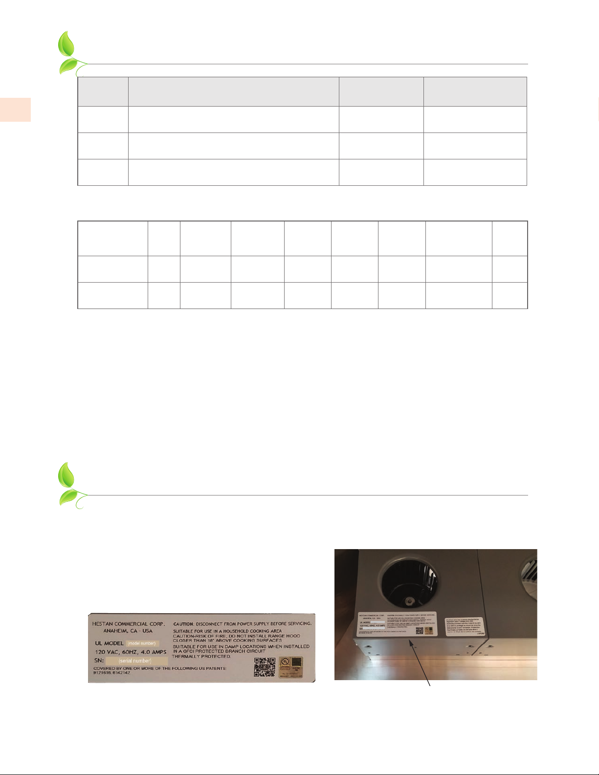
RATING LABEL
The rating label contains important information about your Hestan appliance such as the model and
serial number, electrical rating and the minimum installation clearances.
The rating label is located on the blower housing.
If service is necessary, contact Hestan Customer Care
with the model and serial number information shown
on the label.
(model number)
(serial number)
4
Typical rating label
©2020 Hestan Commercial Corporation
Rating label location
Page 9
REGULATORY / CODE REQUIREMENTS
Installation of this ventilation system must be made in accordance with local codes. In the absence
of local codes, this unit should be installed in accordance with the National Electrical Code and local
codes.
This appliance must be electrically grounded in accordance with local codes or in the absence of local
codes with the National Electrical Code
ANSI/NFPA 70
, or Canadian Electrical code
CSA C22.1
.
USING THE VENTILATION SYSTEM
FEATURES OF THE VENTILATION SYSTEMFEATURES OF THE VENTILATION SYSTEM
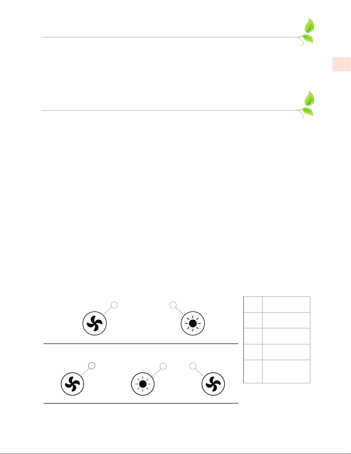
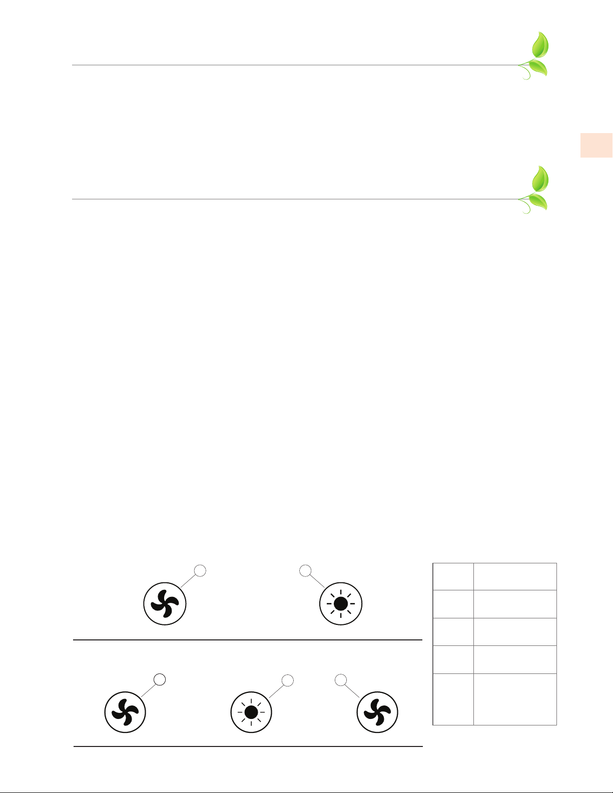
Speed controls are provided for each blower assembly. Two-blower systems will have one speed
control knob, while three or four-blower systems will have two speed control knobs.
A control knob is provided for lighting intensity.
The controls layout will be similar to that shown below.
USING THE HOODUSING THE HOOD
The user can start with the a hood on the lowest setting, and then increase speed and/or turn
on additional blowers as required. Using the hood at high settings may increase heating or air
conditioning requirements and costs for the house.
EN
BLOWER CONTROL KNOB BLOWER CONTROL KNOB
To operate the blower(s), rotate the knob through the blower speed settings by turning it clockwise
(facing the knob).
Rotate the knob counter-clockwise to reduce the blower speed.
LIGHT CONTROL KNOB LIGHT CONTROL KNOB
To operate the lights, rotate the knob through the light intensity settings by turning it clockwise
(facing the knob). Rotate the knob counter-clockwise to dim the lights or turn them off.
Controls for two blowers
1
Controls for three and four blowers
3
2
2
4
Item
Function
Blower control
1
Light control
2
Blower control
3
blowers 1 & 2
Blower control
4
blower 3 or
blowers 3 & 4
©2020 Hestan Commercial Corporation
5
Page 10
CLEANING AND MAINTENANCE
CLEANING THE VENTILATION SYSTEMCLEANING THE VENTILATION SYSTEM
EN
Cleaning requirements depend completely on usage and environment. The more high-heat and/or
greasy cooking, the more often the hood and blower will need cleaning.
The grease tray and blower aren’t visible from the outside, so they must be removed for inspection.
After you’ve inspected the tray a few times over the course of six months or a year, you’ll be able to
set a cleaning schedule according to your usage pattern.
HOOD CANOPYHOOD CANOPY
Wipe down the interior and exterior of the hood as needed with a soft cloth and warm soapy water
(liquid dish detergent is acceptable). Do not use acids, abrasives, strong detergents, solvents, or
scouring pads. Stainless steel should be treated with a quality stainless steel cleaner such as Stainless
Steel Magic®. Follow all label instructions. Do not polish across the grain or in circles.
BLOWER HOUSING AND SHIELD BLOWER HOUSING AND SHIELD
To reduce the risk of personal injury, be sure the power is turned off in
the hood before removing the shield(s) and blower housing(s).
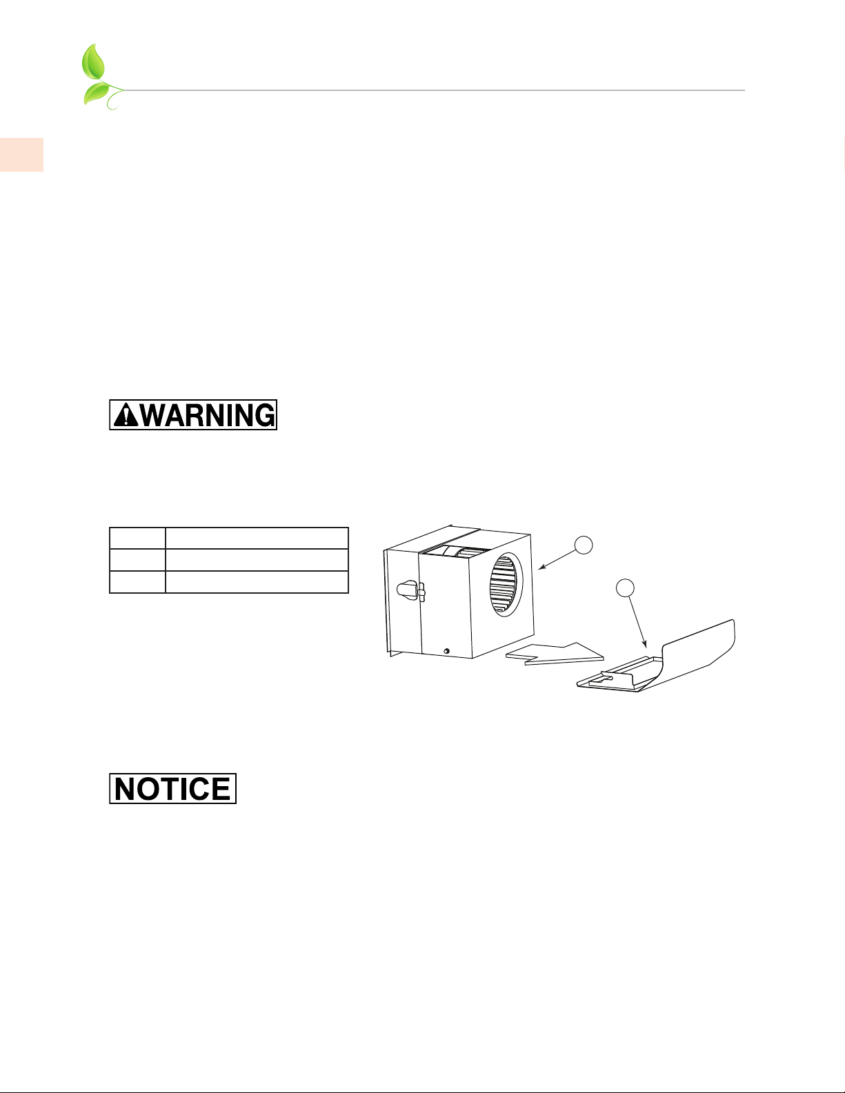
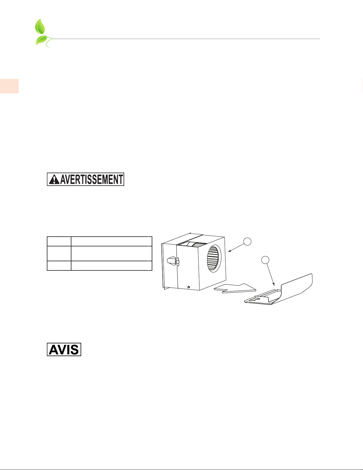
The blower captures grease by-products in the blower housing(s) and blower shield(s). The blower
shields require more frequent cleaning than the blower housing, but cooking usage determines how
often each item will need to be cleaned.
Item # Description
Blower housing with damper(s)
1
Blower shield
2
1
2
6
BLOWER SHIELD REMOVALBLOWER SHIELD REMOVAL
The blower shields are easily removed for cleaning by pulling the blower shield(s) toward the front of
the hood.
Be careful to keep the tray level if the hood has been recently used and the
grease might still be warm.
Inspect and clean the blower shield (Details follow)
BLOWER HOUSING REMOVALBLOWER HOUSING REMOVAL
To remove the blower housing:
1. Unsnap two suitcase latches, one on each side of the housing.
2. Support the housing and pull it away from the blower base.
3. While pulling it back, gently “tip” it downward to clear the blower wheel(s).
©2020 Hestan Commercial Corporation
Page 11
2
CLEANING AND MAINTENANCE
CLEANINGCLEANING
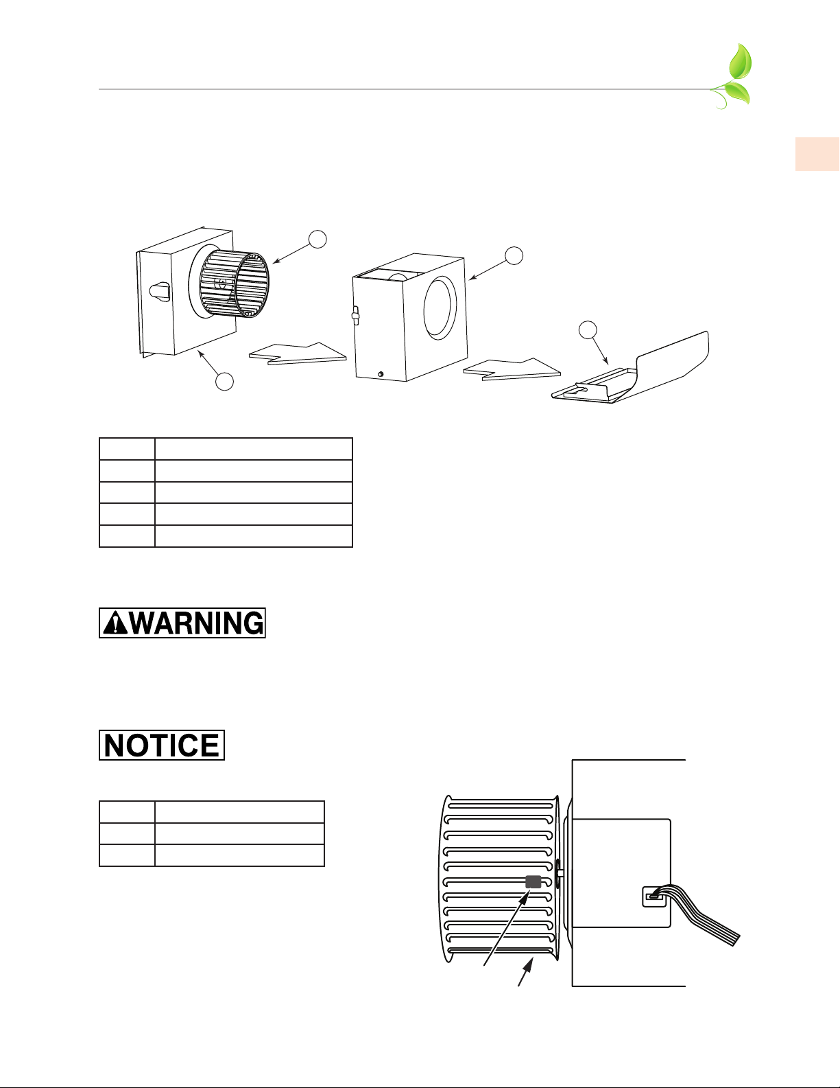
Clean the shield(s) and/or blower housing(s) in a sink of warm soapy water (liquid dish detergent)
and let soak for a few minutes. Wash with a sponge or dishcloth, rinse and let drain before
reinstalling. Alternatively, the blower housing(s) and blower shield(s) may be placed into a
dishwasher. Handle the plastic blower housing dampers with care. They must move freely.
(CONT.)
2
3
4
1
EN
Item #
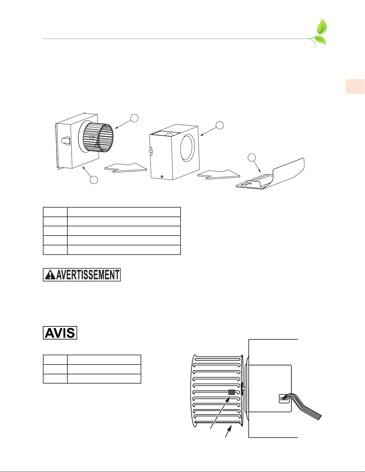
Regular cleaning of the blower housing should prevent grease accumulation on the blower wheel. If
grease build-up should occur, the blower wheel may easily be cleaned in place using a soft bristle
toothbrush and a common degreaser such as Formula 409®.
Item #
Description
Motor housing
1
Wheel
2
Blower housing with damper(s)
3
Blower shield
4
Take care not to move or lose the metal balancing clips that may be affixed to
the wheel.
Description
Balancing clip
1
Blower wheel
2
To reduce the risk of personal injury, be sure the power is turned off in
the hood before removing the shield(s) and blower housing(s).
1
©2020 Hestan Commercial Corporation
7
Page 12

EN
CLEANING AND MAINTENANCE
BLOWER WHEEL REMOVALBLOWER WHEEL REMOVAL
For instances where the blower wheel must be removed, follow the instructions below.
• Removing the blower wheel requires a 1/8” hex wrench. This may be obtained from your local
hardware store or tool supply.
The wheel is retained by a set screw on the side of the hub of the wheel that tightens up against a
“flat” spot on the motor shaft.
1. Locate the set screw on the side of the hub of the wheel.
2. Insert wrench through the blades of the blower wheel and into the set screw.
3. Loosen the set screw 1/2 turn counterclockwise.
(CONT.)
If the wheel is difficult to remove, the area where the motor shaft makes contact with the blower
wheel hub may need to be sprayed with a common penetrating oil such as WD-40
After allowing the penetrating oil to soak for a few minutes, push the blower wheel forward
slightly, then gently pull the blower wheel off the motor shaft.
• Use caution to avoid bending or distorting the blower wheel and take care not to move or lose
the metal balancing clips that may be affixed to the wheel.
A soft bristle toothbrush with warm soapy water may be used to clean the blades, or soak the blower
wheel in warm soapy water.
BLOWER WHEEL INSTALLATIONBLOWER WHEEL INSTALLATION
When reinstalling the wheel onto the motor shaft, make sure the set screw makes direct contact
with the “flat spot” on the motor shaft.
1. Slide the blower wheel onto the motor shaft as far as it will go, making sure the back of the
blower wheel does not touch the motor mount screws protruding from the motor.
• If the motor is too far back, it will rub the motor mount screws, and if it is too far forward, it will
rub the inside of the blower housing.
2. Adjust the blower wheel slightly to find the correct front-to-rear location.
3. Tighten the set screw (clockwise) to lock the blower wheel in the correct position.
For hoods that have more than one blower wheel, make sure that white blower
wheels are matched up with white motor rings, and black blower wheels are
matched up with black motor rings.
®
.
8
The hood will not perform properly if blower wheels and motors are mismatched.
MOTOR REPLACEMENT MOTOR REPLACEMENT
To reduce the risk of personal injury, turn off power to the hood at
the breaker or the circuit disconnect before attempting to remove the
blower motor.
MOTOR IDENTIFICATION AND POSITIONINGMOTOR IDENTIFICATION AND POSITIONING
Motors are color-coded; black and white motors have different rotations and must be installed in the
correct positions.
• Housings with a single blower use a white blower and wheel.
• Housings with two blowers use a white blower on the right and black on the left.
Make sure you have the correct motor in each housing position.
©2020 Hestan Commercial Corporation
Page 13
CLEANING AND MAINTENANCE
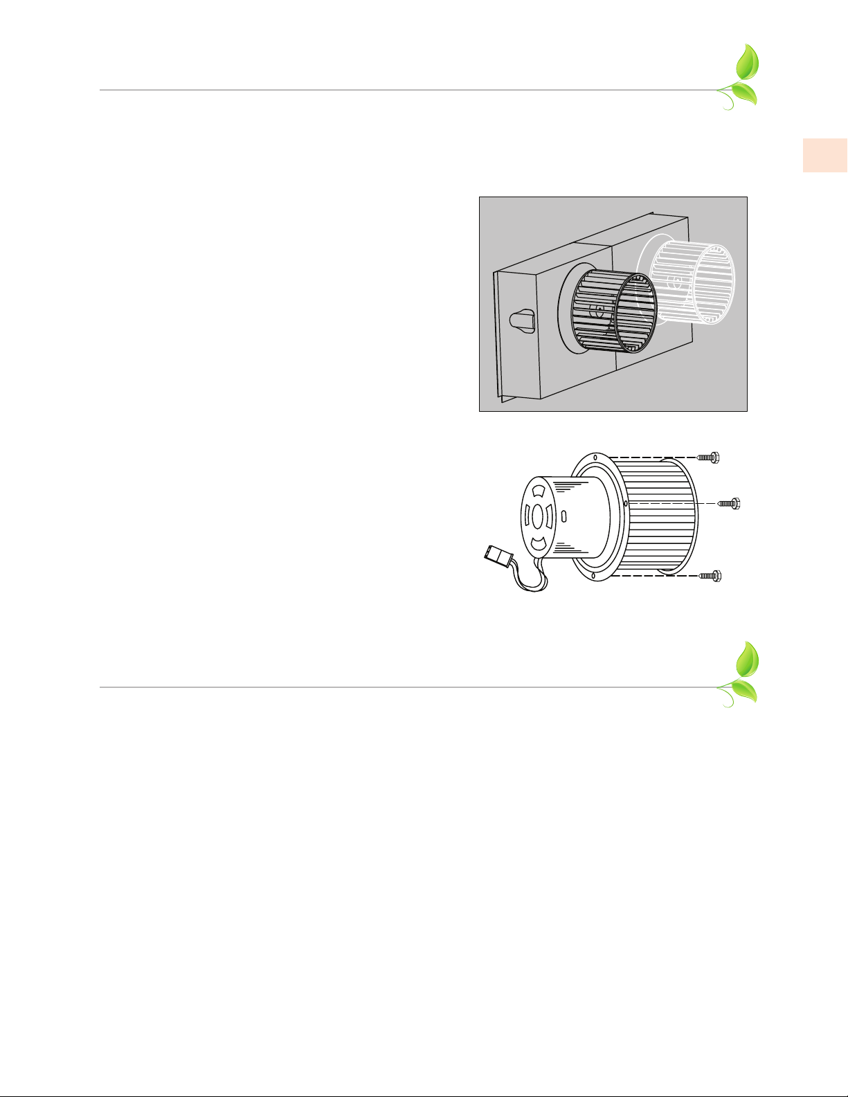
• If the replacement blower motor includes a blower wheel, then you can remove the motor and
wheel together. If you will re-use your existing wheel, then you may wish to remove the wheel
before removing the motor.
1. Remove the shield and blower housing as described in
“BLOWER WHEEL REMOVAL” on page8.
2. Use a ¼” nut driver to remove the three motor mount
screws that attach the motor to the base.
3. Gently pull the motor forward and down.
4. Disconnect the wiring harness, remove the old motor.
• To avoid damage to the blower wheel, you may wish
to install the motor and then install the wheel onto
the motor.
5. Lift the new motor so you can connect the wiring
harness. Be sure to fully engage the electrical
connections and tighten the motor mount screws.
6. Check the blower wheel clearance and adjust as needed,
as described in “BLOWER WHEEL INSTALLATION” on
page8.
(CONT.)
EN
TROUBLESHOOTING
If the hood does not perform satisfactorily, check the following:
• Do the blowers run?
• Are the blower wheels installed on the correct motors? (black wheel on black motor, white wheel
on white motor)
• Are the motor and wheel assemblies installed in the correct locations?
• Check the damper doors in hood behind/above blowers - do they move/open freely?
• Check the dampers/vents to outside - do they open freely, with no obstructions?
• Check for damaged or obstructed ductwork.
©2020 Hestan Commercial Corporation
9
Page 14
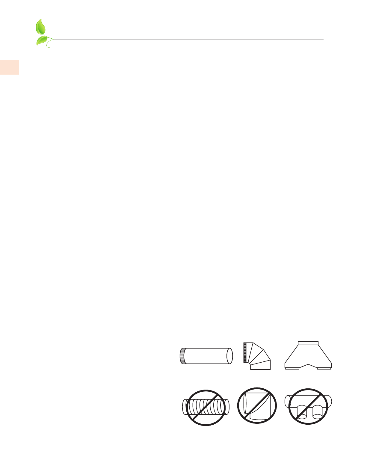
DUCTING DO’S AND DON’TS
GENERAL REQUIREMENTSGENERAL REQUIREMENTS
EN
Observe local codes regarding special duct requirements and placement of duct work against
combustibles.
• Using recommended transitions (see VENT ACCESSORIES) will ensure proper efficiency.
• Using recommended roof caps or wall louvers (see VENT ACCESSORIES) will ensure proper
efficiency.
• Use foil HVAC tape (not grey cloth duct tape) to seal all joints.
• The hood must be ducted to the outdoors without restrictions.
BLOWER REQUIREMENTSBLOWER REQUIREMENTS
The dual blower unit (WM2L, used in all systems) requires 8” round duct or equivalent (50 square
inches). The single blower unit (WM1L, used in addition to the dual blower unit in 900 CFM
systems) requires 6” round duct or equivalent (28 square inches).
COMBINED DUCT SIZE AFTER A TRANSITIONCOMBINED DUCT SIZE AFTER A TRANSITION
Single and Dual (WM1L & WM2L) combine to 10” round or equivalent 79 sq. in. using a multi-blower
transition such as AKVT6810 (Optional).
Two Duals (Two WM2Ls) combine to 12” round or equivalent 113 sq. in. using a multi-blower
transition such as AKVT8812 (Optional).
DUCTING REQUIREMENTS (DO’S AND DON’TS)DUCTING REQUIREMENTS (DO’S AND DON’TS)
• NEVER reduce the duct size. When combining ducts together, the square inch area of the outlet
duct must be equal or greater than the total square inch area of the ducts being combined.
• Only use smooth, galvanized, metal duct. Do not use flexible or corrugated duct. This type of
duct will restrict airflow and reduce performance.
• Make the duct run as short and as straight as possible with as few turns as possible.
• Avoid sharp-angled turns. Instead, use smooth, gradual turns such as adjustable elbows or 45
degree angled turns.
• For duct runs over 20 feet, increase the duct diameter by one inch for every ten feet of duct.
• When planning length, a 90 degree elbow is equivalent to 5 feet of duct.
10
TERMINATION REQUIREMENTS TERMINATION REQUIREMENTS
Airflow must not be restricted at the end of the duct run.
A wall louver or roof cap is required for each duct run.
Every wall louver or roof cap must include a gravity damper to prevent back drafts.
Do not use screen wire or springloaded doors on wall louvers or roof
caps.
Do not terminate venting into an attic
or chimney.
YES
Smooth duct Smooth gradual turn
NO
Flexible duct Sharp angled turns
©2020 Hestan Commercial Corporation
Proper combining
of two ducts
Improper combining
of two ducts
Page 15

INSTALLATION
TO REDUCE THE RISK OF FIRE, ELECTRIC SHOCK, OR INJURY TO
PERSONS, OBSERVE THE FOLLOWING:
a) Installation work and electrical wiring must be done by qualified person(s) in accordance with all
applicable codes and standards, including fire-rated construction.
b) Sufficient air is needed for proper combustion and exhausting of gases through the flue
(chimney) of fuel burning equipment to prevent back drafting. Follow the heating equipment
manufacturer’s guideline and safety standards such as those published by the National Fire
Protection Association (NFPA), and the American Society for Heating, Refrigeration, and Air
Conditioning Engineers (ASHRAE) and the local code authorities.
c) When cutting or drilling into wall or ceiling, do not damage electrical wiring and other hidden
utilities.
d) Ducted fans must always be vented to the outdoors.
TO REDUCE THE RISK OF FIRE, USE ONLY METAL DUCTWORK.
TO REDUCE THE RISK OF FIRE OR ELECTRICAL SHOCK, DO NOT USE THIS BLOWER WITH
ANY SOLID-STATE SPEED CONTROL DEVICE.
INSTALLATION DETAILSINSTALLATION DETAILS
Read all instructions thoroughly before beginning installation. These instructions apply to Hestan
outdoor hoods, when mounted over a Hestan or Aspire grill. YOU MUST FOLLOW THE GRILL
CLEARANCES DESCRIBED IN YOUR GRILL INSTALLATION MANUAL.
EN
FOR NON-COMBUSTIBLE LOCATIONS ONLY!! This appliance is wall-mounted and must NOT
be installed on or next to unprotected combustible construction. A minimum clearance to vertical
combustible material, such as adjacent walls, is 12” [30 cm] on the sides of the appliance (see Fig. 1).
ALL construction materials in the wall immediately behind the vent and the appliance below (usually
a grill), and within the 12” [30 cm] zone must be non-combustible. As an example, if you have a
stucco or tiled surface and wood-frame construction beneath, or wood-frame walls adjacent or
behind, the wood is considered combustible, even though the vent or grill is touching the stucco or
tiled surface, which is non-combustible. In extreme circumstances, the wood could potentially get
hot enough to burn.
Similarly, if you have the hood mounted over a free-standing grill which is parked close to these
surfaces when grilling over an extended period of time, enough radiant heat could reach the wood
and potentially get hot enough to burn, in extreme circumstances.
Construction materials such as metal studs with cement board and stucco/stone surfaces are ideal for
this application.
A minimum of 5” [12.7 cm] clearance behind the grill is needed to open the hood, and to adequately
capture smoke and vapors from the cooking area.
See Fig. 1 on the next page for details.
©2020 Hestan Commercial Corporation
11
Page 16
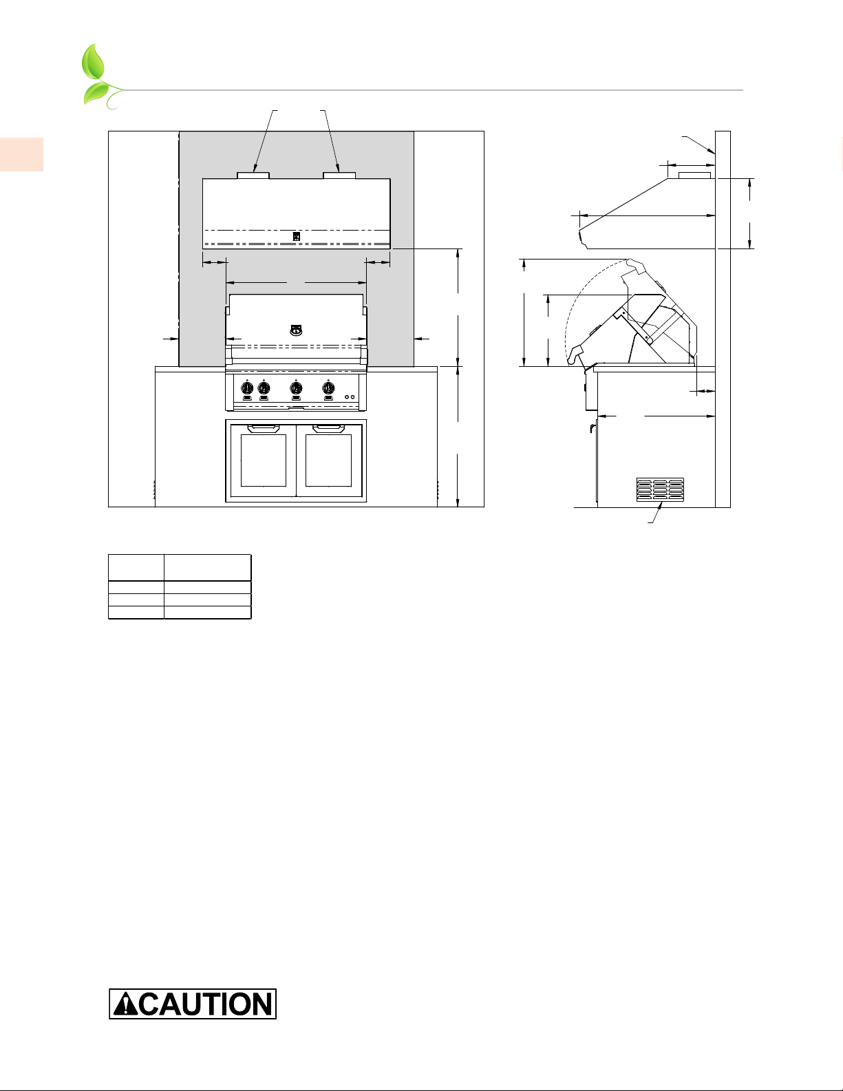
GRILL
RECOMMENDED
42" [106.7]
GVP54
EN
INSTALLATION
(CONT.)
DUCT
OUTLETS
NON-COMBUSTIBLE
CONSTRUCTION
12”
[30.5]
6”
[15.1]
6”
[15.1]
W
30”
[76.2]
12”
[30.5]
NOTES:
* SHADED AREA INDICATES WHERE COMBUSTIBLE MATERIALS ARE NOT ALLOWED.
* "W" IS THE WIDTH OF THE GRILL.
WIDTH
30" [76.2]
36" [91.4]
VENT HOOD
GVP42
GVP48
NON-COMBUSTIBLE CONSTRUCTION ONLY
12”
[30.5]
36”
[91.4]
REF.
(HESTAN GRILL SHOWN)
27.4”
[69.7]
34.6”
[87.9]
18.3”
[46.5]
30”
[76.2]
REF.
ISLAND VENT
OPENINGS
5”
[12.3]
MIN.
18”
[45.7]
Fig. 1
12
1. Read all instructions thoroughly before beginning installation. See “DUCTING DO’S AND
DON’TS” on page10.
• Weight and size: For safe installation, at least two people should be present to lift and hold the
hood. For larger hoods and installations with duct covers, it is advisable to have a third person
present to assist.
• Back Venting: If venting out the wall behind the vent instead of venting through the ceiling, see
“Back Venting” on page18 for details.
2. When installing a wall mount range hood, it is recommended that the bottom edge of the hood
be located 30” [76.2 cm] above the cooking surface for optimum performance.
3. Select the appropriate installation method.
Method 1 is suitable for applications where the top of the hood (blower outlet(s) location) is
accessible after the hood is mounted on the wall and when a Hestan duct cover will be used.
• NOTE: Since Hestan duct covers can be opened for access, they can be installed with the hood
and still permit access to connection points. The duct cover frame requires that the hood and
duct cover be installed together.
Method 2 is suitable for applications where the top of the hood (blower outlet(s) location) is not
accessible after the hood is mounted on the wall.
Make sure that once the hood is mounted the motor cooling vents are
not obstructed.
©2020 Hestan Commercial Corporation
Page 17
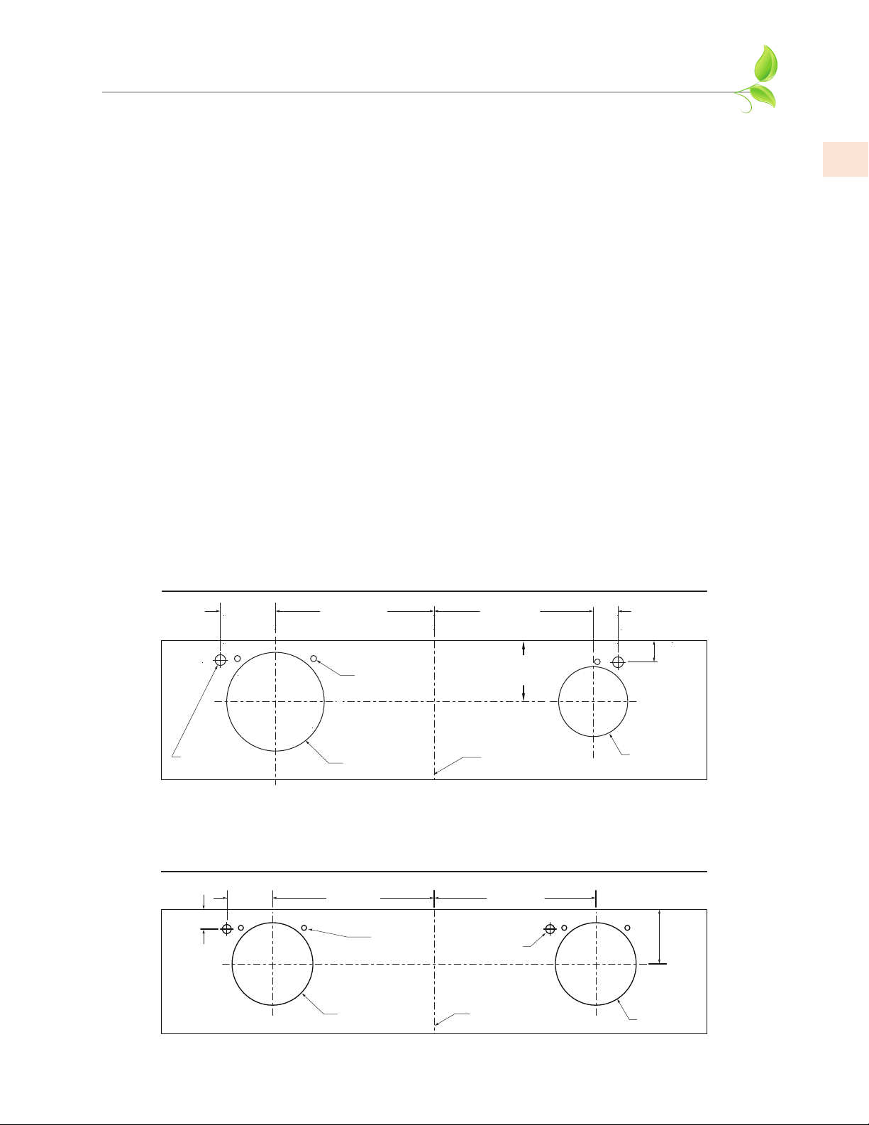
Connection Diagram (42” width)
WM2L Dual + WM1L Single Blower (900 CFM)
Connection Diagram (48-54” widths)
Two WM2L Dual Blowers (1200 CFM)
INSTALLATION
(CONT.)
4. IF THE HOOD IS TO BE “BACK VENTED”, PROCEED DIRECTLY TO STEP 5.
Consult the connection diagrams (following) for further details on exhaust outlet placement.
Method 1: Install the duct(s) from the outside of the home down to the location of the exhaust
outlet(s) on the top of the hood or to the transition (if applicable).
• If a transition is used, install duct down to the location of the transition outlet plus 1”
[2.5 cm]. This will allow the transition to engage 1” [2.5 cm] inside of duct.
Method 2: Install the duct(s) from the outside of the home to the ceiling over the exhaust
outlet(s) on the hood. The end of the duct(s) should extend 1” [2.5 cm] below the
ceiling.
Use foil HVAC tape (not grey cloth duct tape) to seal all joints. See “VENT ACCESSORIES” on
page19 for a listing of available Hestan ducting materials.
TRANSITION HEIGHTS:TRANSITION HEIGHTS:
Single and Dual Blower (WM1L + WM2L = 900 CFM): 6” round duct will connect directly to
the top of the hood; 8” round will connect directly to the top of the hood. If using
the optional multi-blower transition (AKVT6810, sold seperately), a 10” round duct
connects to it 17-1/2” above top of hood. See “VENT ACCESSORIES” on page19 for
details.
Two Dual Blowers (Two WM2Ls = 1200 CFM): Two 8” round ducts connect directly to the
top of the hood. If using the optional multi-blower transition (AKVT8812, sold
seperately), a 12” round duct connects to it 16-1/2” above top of hood. See “VENT
ACCESSORIES” on page19 for details.
CONNECTION DIAGRAMS CONNECTION DIAGRAMS
EN
5-1/2"
[14 cm]
(Wall Side)
Electrical (2)
7-5/16"
[18.6 cm]
Motor
Cooling
Vent (3)
8" Round
7-5/16"
[18.6 cm]
5-1/4"
[13.3 cm]
Centerline
of hood
1-7/8"
[4.8 cm]
1-3/4"
[4.4 cm]
6" [15.2 cm]
Round
(Top View)
5-1/2"
[14 cm]
1-3/4"
[4.4 cm]
11"
[29.9 cm]
Motor
Cooling
Vent (4)
8" [20.3 cm]
Round
Electrical (2
11"
[29.9 cm]
)
Centerline
of Hood
(Wall Side)
5-1/4"
[13.3 cm]
8" [20.3 cm]
Round
(Top view)
©2020 Hestan Commercial Corporation
13
Page 18

EN
INSTALLATION
5. Remove the hood from its packaging and place the back of the hood on the floor or countertop
in front of the wall where it will hang.
6. With the hood on its back facing you, remove the blower shield(s) and blower housing(s) as
follows:
a) Remove the shipping tape that is securing the blower shield(s) inside the hood.
b) Remove the blower shield(s) by lightly pulling it toward the front of the hood.
c) Gently close the back draft damper(s) from the top side of the hood.
d) To remove the blower housing(s), unsnap the suitcase latches (one on each side of the
housing).
e) Support the housing and lift it away from the blower base, then tip it back toward you to
clear the blower wheel(s), and then pull it from the hood.
7. One blower motor must be removed from each blower assembly to access the connection
box(es). The blower assembly will have a decal identifying the location of the connection
box(es). It is not necessary to remove the blower wheel from the motor.
a) Remove the three screws retaining the blower motor.
(CONT.)
Make sure power is off at the supply panel / breaker during service or
installation.
b) Pull the motor out far enough so you can reach its electrical connector.
c) Unplug the connector, set the blower motor and screws aside.
8. WIRING PREPARATION:
a) Install an appropriate 1/2” UL listed electrical wire clamp through each motor box
electrical opening on top of the hood.
b) Install electrical wiring from the service panel to the hood location for each motor box.
Consult the connection diagrams (on previous page) for further details on electrical
placement. See “ELECTRICAL SUPPLY AND GROUNDING” on page1 for power
requirements.
Method 1: Extend wiring to 30” [76.2 cm] above the countertop. Electrical connection(s)
will occur after the hood is installed on the wall.
Method 2: Extend wiring to the hood. Electrical connection(s) will occur before the
hood is installed on the wall.
9. Mark the wall at the lower edge of the hood opening:
a) If using a duct cover:
i. Carefully remove the knockouts from the top four corners of the hood.
ii. Remove the duct cover from its packaging and remove the mounting screws from the
base of the duct cover.
14
iii. Place the duct cover on the top of the hood and secure it temporarily through the knock-
out openings using the mounting screws previously removed.
• The front panel may be removed from the duct cover during handling to reduce
weight.
b) Lift the hood (and duct cover assembly if used) to the location on the wall where it will be
installed.
©2020 Hestan Commercial Corporation
Page 19

INSTALLATION
c) Lightly mark the wall with a short, horizontal mark along the bottom edge of the hood.
(CONT.)
d) When finished, remove the hood and duct cover assembly from the wall.
10. Find location of mounting strip:
a) On the back side of the hood, measure the distance between the bottom edge of the hood
and the top edge of the wood mounting strip.
b) Measure this distance above the horizontal mark made in Step 9 and lightly mark the wall
with a level, horizontal line.
c) Measure where the center (left to right) of the hood will be and mark the upper,
horizontal line on the wall with a short, vertical centerline.
11. Attach the mounting strip to the wall as follows:
a) Remove the screws inside the top of the back of the hood that retain the wood strip that
is recessed in the mounting channel. Note: Some retaining screws may be located behind
the blower(s).
b) Remove the wood mounting strip from the back of the hood and place the top edge of the
strip on the upper, level, horizontal line on the wall.
c) Referencing the vertical centerline from Step 10, place the mounting strip on the wall so
it is centered (left to right) in the space where the hood will be located. Mark the strip at
two or more stud locations, and drill clearance holes in the strip to prevent splitting.
d) Using proper hardware, attach the mounting strip to at least two wall studs.
Note: for 48” [122 cm] and larger hoods, three screws into studs are recommended.
EN
12. FOR BACK VENTING APPLICATIONS ONLY. IF NOT BACK VENTING, PROCEED DIRECTLY
TO STEP 13.
• Note: Wall studs may interfere with back venting installations. Additional framing may be
required. It is necessary to cut duct access hole(s) in the wall prior to installing the hood.
• If using a duct cover, this step may be done with the duct cover removed from the hood. The
duct cover must still be mounted to the hood before mounting the hood to the wall.
Method 1:
a) Hold the hood on the mounting strip by aligning the channel at the top of the back of the
hood over the wood mounting strip on the wall.
b) Place the appropriate elbow(s) on top of the hood in line with the hood exhaust collar(s).
On the wall, trace around the elbow(s). Remove the hood and elbow(s) from the wall.
c) Cut around the outside of the traced line(s), avoiding wall studs. Install the duct from the
outside of the home to the opening in the wall. Use HVAC foil tape (not grey cloth duct
tape) to seal joints.
d) Proceed to step 14.
Method 2:
a) Use the the connection diagrams (page13), “BACK VENTING” on page18 , and “VENT
ACCESSORIES” on page19 as a guide. Install the duct(s) from the outside of the home to
the wall so they will meet the exhaust elbows to be used.
b) The end of the duct(s) should extend 1” past the ends of the elbows.
c) Proceed to step 14.
©2020 Hestan Commercial Corporation
15
Page 20

INSTALLATION
13. Check mount holes to wood strip, drill if needed:
(CONT.)
EN
a) Hang the hood on the mounting strip by aligning the channel at the top of the back of the
hood over the wood mounting strip on the wall.
b) While holding the hood in place, determine if the mounting holes in the channel at the top
of the back of hood align with the existing holes in the mounting strip. If they don’t, mark
the hole locations on the mounting strip.
c) Remove the hood and drill 3/32” pilot holes in the center of the marks in the wooden
mounting strip to avoid splitting.
14. MOUNTING THE HOOD:
FOR BACK VENTING APPLICATIONS ONLY. IF YOU ARE NOT BACK VENTING, PROCEED
DIRECTLY TO STEP 15.
• If using a Hestan duct cover, it must be mounted to the hood using the provided fasteners before
continuing.
Method 1:
a) Place the appropriate elbow(s) on the top of the hood. Elbow(s) should be placed with
the non-crimped end(s) on the inside of the collar(s) of the exhaust outlet(s). Use HVAC
foil tape (not grey cloth duct tape) to seal joints.
b) Lift the hood up to the wall and hang the hood on the mounting strip, taking care to
properly align the duct connection(s) between the elbow(s) and the duct(s) in the wall.
c) Secure the hood to the mounting strip by installing the screws (previously removed from
the strip in Step 11) into the pilot holes drilled in Step 13.
• Caution must be taken to avoid scratching the hood or ceiling.
Method 2:
a) Place the appropriate elbow(s) on the top of the hood. Elbow(s) should be placed with
the non-crimped end(s) on the inside of the collar(s) of the exhaust outlet(s). Use HVAC
foil tape (not grey cloth duct tape) to seal joints.
b) Insert the electrical wire from the service panel into the electrical wire clamp on each
motor box. Tighten the wire clamp(s).
c) While securing the slack in the wire, lift the hood up to the wall and hang the hood on the
mounting strip, taking care to properly align the duct connection(s) between the elbow(s)
on the hood and the duct(s) in the wall.
d) Secure the hood to the mounting strip by installing the screws (previously removed from
the strip in Step 11) into the pilot holes drilled in Step 13.
• IF BACK VENTING, SKIP STEP 15. PROCEED DIRECTLY TO STEP 16.
15. Mounting the Hood, NON-Back Venting:
If using a transition, install it on the insides of the exhaust collars and seal with HVAC tape (not
grey cloth duct tape). Then mount the hood as follows:
Method 1:
a) Lift the hood (and duct cover, if used) up to the wall and hang the hood on the mounting
strip, taking care to properly align the duct connection(s) between the hood and the duct
in the ceiling.
16
b) Secure the hood to the mounting strip by installing the screws (previously removed from
the strip in Step 11) into the pilot holes drilled in Step 13.
©2020 Hestan Commercial Corporation
Page 21

INSTALLATION
c) Use HVAC tape (not grey cloth duct tape) to seal joints. Insert the electrical wire from the
service panel into the electrical wire clamp on each motor box.
d) Tighten the wire clamp(s).
Method 2:
a) Insert the electrical wire from the service panel into the electrical wire clamp on each
motor box. Tighten the wire clamp(s).
b) If not using a transition, cut a piece of duct for each outlet of sufficient length to meet the
duct(s) in the ceiling.
c) If a transition is used, cut the duct to reach the transition outlet plus 1”. This will allow
the transition to engage 1” inside of the duct. See “TRANSITION HEIGHTS:” on page13.
d) One end of the duct must be crimped to fit inside the duct in the ceiling. Insert the non-
crimped end over the transition or into the exhaust collar(s) on the top of the hood and
seal with HVAC tape.
e) While securing the slack in the wire, lift the hood up to the wall and hang the hood on the
mounting strip, taking care to properly align the duct connection(s) between the hood and
the duct in the ceiling.
f) Secure the hood to the mounting strip by installing the screws (previously removed from
the strip in Step 11) into the pilot holes drilled in Step 13.
(CONT.)
EN
16. If a Hestan duct cover is used, it should be secured to at least one stud using the nailing strips.
The duct cover front panel should then be installed.
17. WIRING CONNECTION:
From inside the hood, using UL listed wire nuts, attach the “neutral” wire(s) to the white lead(s),
the “hot” wire(s) to the black lead(s), and the ground wire(s) to the green lead(s) inside the motor
box(es).
DO NOT OPERATE HOOD WITHOUT PROPER GROUND
CONNECTION.
18. Install the blowers motor(s) by plugging the wiring connectors in and securing the blower
motor(s) using the retaining screws that were removed in Step 7.
19. Replace the blower housing(s) and the blower shield(s). Make sure that the damper(s) open and
close smoothly.
20. Turn power ON, verify operation: See “USING THE VENTILATION SYSTEM” on page5 for
proper hood operation. Test all blower and light functions to ensure they are operating properly.
©2020 Hestan Commercial Corporation
17
Page 22
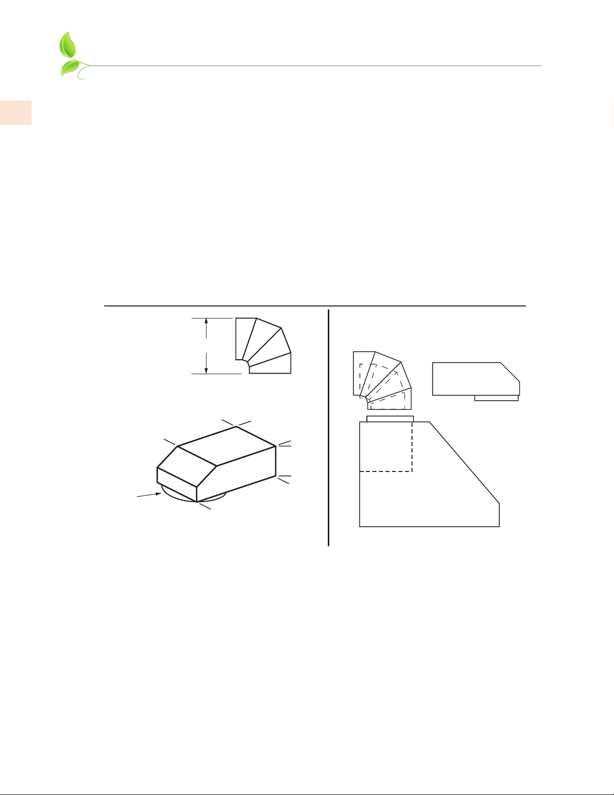
INSTALLATION
BACK VENTINGBACK VENTING
(CONT.)
EN
When venting out through the wall, one or two elbows are required, depending on the blower
configuration:
DUCT COVERS AND BACK VENTINGDUCT COVERS AND BACK VENTING
Low profile elbows may interfere with the duct cover frame. Mount the duct cover to the hood, and
test fit the elbow(s) to confirm proper fit.
ELBOWS FOR 900 CFM ELBOWS FOR 900 CFM
Units with 900 CFM blower systems require one 8” elbow and one 6” elbow.
ELBOWS FOR 1200 CFMELBOWS FOR 1200 CFM
Hoods with 1200 CFM blower systems require two 8” elbows, one for each 600 CFM blower unit.
Elbow and Transition Heights
600 CFM fan module uses 8” round
Height when
fully adjusted to
90 degrees:
Standard 6” [15.2 cm] round, H=8-1/2” [21.6 cm]
Standard 8” [20.3 cm] round, H=10-3/4” [27.3 cm]
H
12”
[30.5 cm]
8 ½”
[21.6 cm]
300 CFM fan module uses 6” round
(Drawing Not To Scale)
8” Round
8” Round
[20.3 cm]
Low profile Elbow: 8” Round to 6 x 8-1/2” Rect.
Hestan P/N AKVBE8
16”
[40.6 cm]
6”
[15.2 cm]
Side View
18
©2020 Hestan Commercial Corporation
Page 23
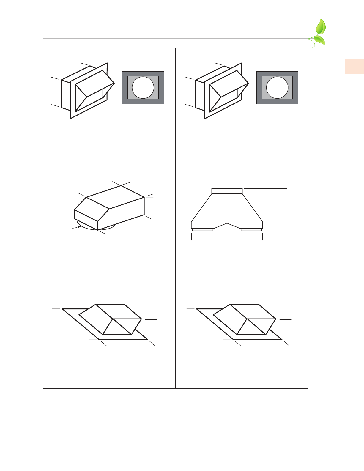
VENT ACCESSORIES
WALL LOUVER
A, B: 8-5/8”
A: 6”
B: 8”
MODEL DESCRIPTION
AKVWL6 6” Round
A
AKVWL8 8” Round
B
12”
8” Round
MODEL DESCRIPTION
AKVBE8
8” Round to 6” x 8-1/2” Rect.
Back
View
1-½” Flange
8-½”
16”
WALL LOUVER
A: 11”
B: 13”
A
B
A: 11”
B: 13”
MODELITEM ITEM
DESCRIPTION
AKVWL10 10” Round
AKVWL12 12” Round
Back
View
1-½” Flange
EN
MULTI-BLOWER TRANSITIONLOW PROFILE ELBOW
A: 10”
B: 12”
A:
6”
A:
23-¼”
B:
30-½”
ITEM
A
B
MODEL DESCRIPTION
AKVT6810 6” & 8” to 10”
AKVT8812 8” & 8” to 12”
17-½”
B:
16-½”
LOW PROFILE ROOF CAP
(MINIMUM 4/12 PITCH)
16-¾”
16-¾”
MODEL DESCRIPTION
AKVRC6HP 6” Round
AKVRC8HP 8” Round
THE INFORMATION IN THIS DOCUMENT IS SUBJECT TO CHANGE AT ANY TIME WITHOUT NOTICE.
6-½”
LOW PROFILE ROOF CAP
(MINIMUM 4/12 PITCH)
22-½”
20-¾”
MODEL DESCRIPTION
AKVRC10HP 10” Round
AKVRC12HP 12” Round
©2020 Hestan Commercial Corporation
10-½”
19
Page 24
EN
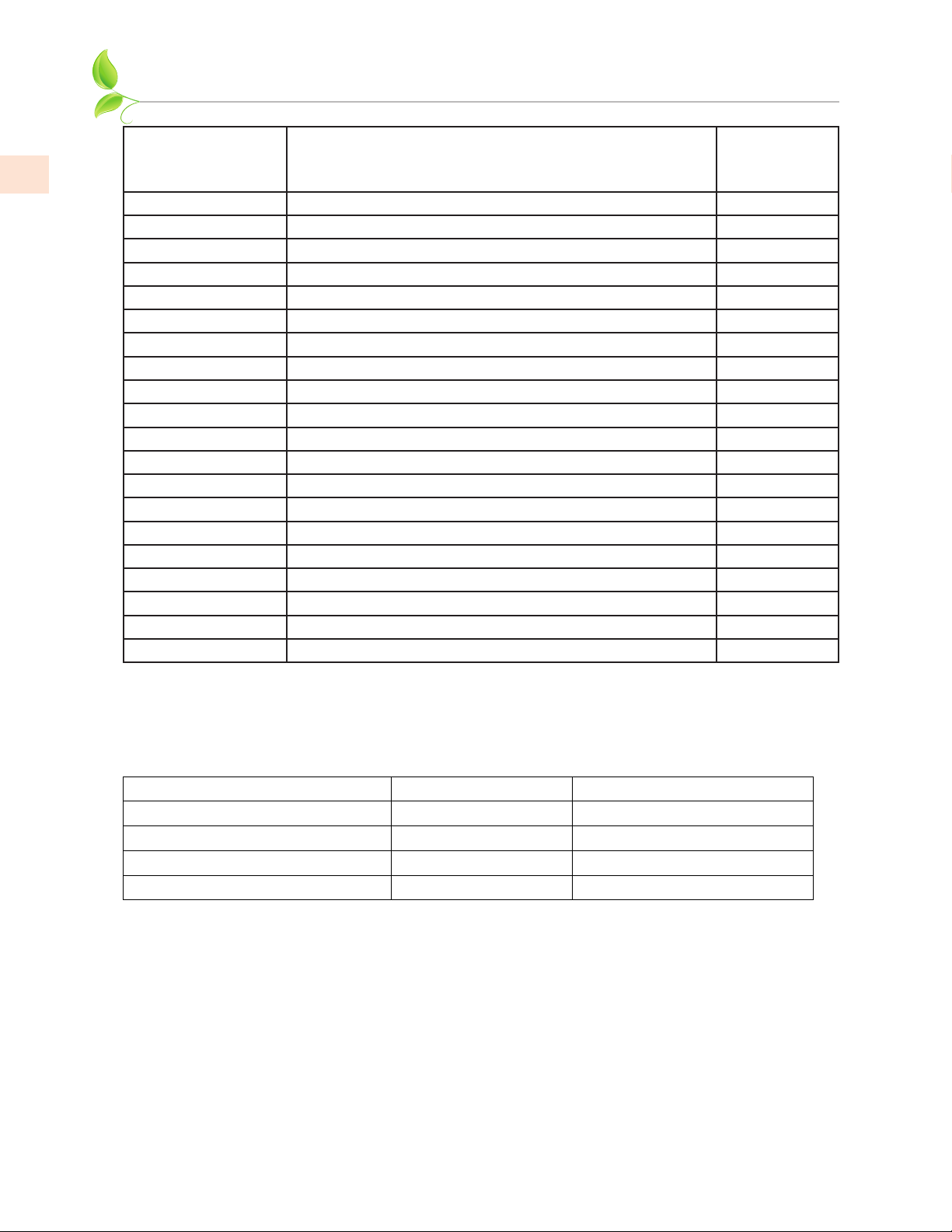
DUCT COVERS
USE WITH
MODEL # DESCRIPTION
KVDC4212 DUCT COVER, VENTILATION, 42W X 12H GVP42
KVDC4212-XX DUCT COVER, VENTILATION, 42W X 12H (COLOR) GVP42
KVDC4812 DUCT COVER, VENTILATION, 48W X 12H GVP48
KVDC4812-XX DUCT COVER, VENTILATION, 48W X 12H (COLOR) GVP48
KVDC5412 DUCT COVER, VENTILATION, 54W X 12H GVP54
KVDC5412-XX DUCT COVER, VENTILATION, 54W X 12H (COLOR) GVP54
KVDC4224 DUCT COVER, VENTILATION, 42W X 24H GVP42
KVDC4224-XX DUCT COVER, VENTILATION, 42W X 24H (COLOR) GVP42
KVDC4824 DUCT COVER, VENTILATION, 48W X 24H GVP48
KVDC4824-XX DUCT COVER, VENTILATION, 48W X 24H (COLOR) GVP48
KVDC5424 DUCT COVER, VENTILATION, 54W X 24H GVP54
KVDC5424-XX DUCT COVER, VENTILATION, 54W X 24H (COLOR) GVP54
KVDC4236 DUCT COVER, VENTILATION, 42W X 36H GVP42
KVDC4236-XX DUCT COVER, VENTILATION, 42W X 36H (COLOR) GVP42
KVDC4836 DUCT COVER, VENTILATION, 48W X 36H GVP48
KVDC4836-XX DUCT COVER, VENTILATION, 48W X 36H (COLOR) GVP48
KVDC5436 DUCT COVER, VENTILATION, 54W X 36H GVP54
KVDC5436-XX DUCT COVER, VENTILATION, 54W X 36H (COLOR) GVP54
HOOD
MODEL #
NOTE: -XX indicates color model.NOTE: -XX indicates color model.
COLOR EXTENSION NUMBERS COLOR EXTENSION NUMBERS
-BK for Stealth - Black -WH for Froth - White -RD for Matador - Red
-YW for Sol - Yellow -OR for Citra - Orange -BG for Tin Roof - Burgundy
-PP for Lush - Purple -BU for Prince - Blue -GR for Grove - Green
-GG for Pacific Fog - Graphite Gray -TQ for Bora Bora – Turquoise
-PK for Reef - Pink -DB for Orion - Dark Blue
20
©2020 Hestan Commercial Corporation
Page 25

PARTS / SERVICE
SERVICE DATA RECORDSERVICE DATA RECORD
The rating label contains the model number and serial number of the appliance. See page4 for
the location of the rating label.
Now is a good time to write this information in the space provided below. Keep your invoice for
warranty validation.
Model Number _________________________________
Serial Number __________________________________
Date of Installation or Occupancy __________________
PARTS LIST
Please visit the Hestan website to access the parts list for your Hestan Outdoor product:
www.hestanhome.com.www.hestanhome.com.
SERVICE
All warranty and non-warranty repairs should be performed by qualified service personnel. To locate
an authorized service agent in your area, contact your Hestan dealer, local representative, or the
manufacturer. Before you call, please have the model number and serial number information ready.
EN
Hestan Commercial Corporation
3375 E. La Palma Avenue
Anaheim, CA 92806
(888) 905-7463
LIMITED WARRANTY
WHAT THIS LIMITED WARRANTY COVERSWHAT THIS LIMITED WARRANTY COVERS
Hestan Commercial Corporation (“HCC”) warrants to the original consumer purchaser of a Hestan
Outdoor Cooking product (the “Product”) from an HCC authorized dealer that the Product is free
from defective materials or workmanship for a period of two (2) years from the date of original
retail purchase or closing date for new construction, whichever period is longer (“Limited Warranty
Period”). HCC agrees to repair or replace, at HCC’s sole option, any part or component of the
Product that fails due to defective materials or workmanship during the Limited Warranty Period.
This Limited Warranty is not transferable and does not extend to anyone beyond the original
consumer purchaser (“Purchaser”). This Limited Warranty is valid only on Products purchased and
received from an HCC authorized dealer in the fifty United States, the District of Columbia and
Canada. This Limited Warranty applies only to Products in non-commercial use and does not extend
to Products used in commercial applications.
©2020 Hestan Commercial Corporation
21
Page 26

EN
LIMITED WARRANTY
HOW TO OBTAIN WARRANTY SERVICEHOW TO OBTAIN WARRANTY SERVICE
If the Product fails during the Limited Warranty Period for reasons covered by this Limited Warranty,
the Purchaser must immediately contact the dealer from whom the Product was purchased or HCC
at 888.905.7463.
Purchaser is responsible for making the Product reasonably accessible for service or for paying the
cost to make the Product reasonably accessible for service. Service is to be provided during normal
business hours of the authorized Hestan Commercial Service Provider. To the extent Purchaser
requests service outside of the normal business hours of the authorized Hestan Commercial Service
Provider, Purchaser will pay the difference between regular rates and overtime or premium rates.
Purchaser is required to pay all travel costs for travel beyond 50 miles (one way) from the nearest
authorized Hestan Commercial Service Provider.
EXTENSIONS TO TWO YEAR LIMITED WARRANTY PERIOD:EXTENSIONS TO TWO YEAR LIMITED WARRANTY PERIOD:
IN ADDITION TO THE TWO-YEAR LIMITED WARRANTY, THE FOLLOWING COMPONENTS
HAVE EXTENDED WARRANTY COVERAGE AS SPECIFICALLY SET FORTH BELOW:
1. The Product’s gas burners (excludes appearance), electric heating elements, blower motors
(ventilation hoods), electronic control boards, magnetron tubes and induction generators
(where applicable) are warranted to be free from defects in material and workmanship under
normal non-commercial use and service for a period of five (5) years of the original Purchaser.
This excludes surface corrosion, scratches, and discoloration which may occur during normal
use and is limited to replacement of the defective part(s), with the Purchaser paying all other
costs, including labor, shipping and handling, as applicable.
(CONT.)
WHAT THIS LIMITED WARRANTY DOES NOT COVER:WHAT THIS LIMITED WARRANTY DOES NOT COVER:
This Limited Warranty does not cover and HCC will not be responsible for and will not pay for:
damage to or defects in any Product not purchased from an HCC authorized dealer; color variations
in color finishes or other cosmetic damage; failure or damage from abuse, misuse, accident, fire,
natural disaster, commercial use of the Product, or loss of electrical power or gas supply to the
Product; damage from alteration, improper installation, or improper operation of the Product;
damage from improper or unauthorized repair or replacement of any part or component of the
Product; damage from service by someone other than an authorized agent or representative of the
Hestan Commercial Service Network; normal wear and tear; damage from exposure of the Product
to a corrosive atmosphere containing chlorine, fluorine, or any other damaging chemicals; damage
resulting from the failure to provide normal care and maintenance to the Product; damage HCC
was not notified of within the Limited Warranty Period; and incidental and consequential damages
caused by any defective material or workmanship.
ARBITRATION:ARBITRATION:
This Limited Warranty is governed by the Federal Arbitration Act. Any dispute between Purchaser
and HCC regarding or related to the Product or to this Limited Warranty shall be resolved by binding
arbitration only on an individual basis with Purchaser. Arbitration will be conducted by the American
Arbitration Association (“AAA”) in accordance with its Consumer Arbitration Rules or by JAMS. The
arbitration hearing shall be before one arbitrator appointed by the AAA or JAMS. The arbitrator shall
not conduct class arbitration and Purchaser shall not bring any claims against HCC in a representative
capacity on behalf of others.
LIMITATION OF LIABILITY:LIMITATION OF LIABILITY:
This Limited Warranty is the final, complete and exclusive agreement between HCC and Purchaser
regarding the Product.
22
©2020 Hestan Commercial Corporation
Page 27

LIMITED WARRANTY
THERE ARE NO EXPRESS WARRANTIES OTHER THAN THOSE LISTED AND DESCRIBED ABOVE. THERE ARE NO EXPRESS WARRANTIES OTHER THAN THOSE LISTED AND DESCRIBED ABOVE.
NO WARRANTIES WHETHER EXPRESS OR IMPLIED, INCLUDING, BUT NOT LIMITED TO, ANY NO WARRANTIES WHETHER EXPRESS OR IMPLIED, INCLUDING, BUT NOT LIMITED TO, ANY
IMPLIED WARRANTIES OF MERCHANTABILITY OR FITNESS FOR A PARTICULAR PURPOSE IMPLIED WARRANTIES OF MERCHANTABILITY OR FITNESS FOR A PARTICULAR PURPOSE
SHALL APPLY AFTER THE LIMITED WARRANTY PERIOD STATED ABOVE. NO OTHER EXPRESS SHALL APPLY AFTER THE LIMITED WARRANTY PERIOD STATED ABOVE. NO OTHER EXPRESS
WARRANTY OR GUARANTY GIVEN BY ANY PERSON, FIRM OR CORPORATION WITH RESPECT WARRANTY OR GUARANTY GIVEN BY ANY PERSON, FIRM OR CORPORATION WITH RESPECT
TO THIS PRODUCT SHALL BE BINDING ON HCC. HCC ASSUMES NO RESPONSIBILITY TO THIS PRODUCT SHALL BE BINDING ON HCC. HCC ASSUMES NO RESPONSIBILITY
THAT THE PRODUCT WILL BE FIT FOR ANY PARTICULAR PURPOSE, EXCEPT AS OTHERWISE THAT THE PRODUCT WILL BE FIT FOR ANY PARTICULAR PURPOSE, EXCEPT AS OTHERWISE
PROVIDED BY APPLICABLE LAW.PROVIDED BY APPLICABLE LAW.
HCC SHALL NOT BE LIABLE FOR LOSS OF REVENUE OR PROFITS, FAILURE TO REALIZE HCC SHALL NOT BE LIABLE FOR LOSS OF REVENUE OR PROFITS, FAILURE TO REALIZE
SAVINGS OR OTHER BENEFITS, OR ANY OTHER SPECIAL, INCIDENTAL OR CONSEQUENTIAL SAVINGS OR OTHER BENEFITS, OR ANY OTHER SPECIAL, INCIDENTAL OR CONSEQUENTIAL
DAMAGES CAUSED BY THE USE, MISUSE OR INABILITY TO USE THE PRODUCT, REGARDLESS DAMAGES CAUSED BY THE USE, MISUSE OR INABILITY TO USE THE PRODUCT, REGARDLESS
OF THE LEGAL THEORY ON WHICH THE CLAIM IS BASED, AND EVEN IF HCC HAS BEEN OF THE LEGAL THEORY ON WHICH THE CLAIM IS BASED, AND EVEN IF HCC HAS BEEN
ADVISED OF THE POSSIBILITY OF SUCH DAMAGES. NO RECOVERY OF ANY KIND AGAINST ADVISED OF THE POSSIBILITY OF SUCH DAMAGES. NO RECOVERY OF ANY KIND AGAINST
HCC SHALL BE GREATER IN AMOUNT THAN THE PURCHASE PRICE OF THE PRODUCT. HCC SHALL BE GREATER IN AMOUNT THAN THE PURCHASE PRICE OF THE PRODUCT.
WITHOUT LIMITING THE FOREGOING, YOU ASSUME ALL RISK AND LIABILITY FOR LOSS, WITHOUT LIMITING THE FOREGOING, YOU ASSUME ALL RISK AND LIABILITY FOR LOSS,
DAMAGE OR INJURY TO YOU AND YOUR PROPERTY AND TO OTHERS AND THEIR PROPERTY DAMAGE OR INJURY TO YOU AND YOUR PROPERTY AND TO OTHERS AND THEIR PROPERTY
ARISING OUT OF THE USE, MISUSE OR INABILITY TO USE THE PRODUCT NOT CAUSED ARISING OUT OF THE USE, MISUSE OR INABILITY TO USE THE PRODUCT NOT CAUSED
DIRECTLY BY THE NEGLIGENCE OF HCC. THIS LIMITED WARRANTY STATES YOUR EXCLUSIVE DIRECTLY BY THE NEGLIGENCE OF HCC. THIS LIMITED WARRANTY STATES YOUR EXCLUSIVE
REMEDY.REMEDY.
(CONT.)
EN
No oral or written representation or commitment given by anyone, including but not limited to, an
employee, representative or agent of HCC will create a warranty or in any way increase the scope of
this express Limited Two Year Warranty. If there is any inconsistency between this Limited Warranty
and any other agreement or statement included with or relating to the Product, this Limited
Warranty shall govern. If any provision of this Limited Warranty is found invalid or unenforceable, it
shall be deemed modified to the minimum extent necessary to make it enforceable and the remainder
of the Limited Warranty shall remain valid and enforceable according to its terms.
INTERACTION OF LAWS WITH THIS LIMITED WARRANTY:INTERACTION OF LAWS WITH THIS LIMITED WARRANTY:
Some states, provinces or territories may not allow limitations on how long an implied warranty
lasts or the exclusion or limitation of incidental or consequential damages, so the above limitations
or exclusions may not apply to you. Some states, provinces or territories may provide for additional
warranty rights and remedies, and the provisions contained in this Limited Warranty are not intended
to limit, modify, take away from, disclaim or exclude any mandatory warranty requirements provided
by states, provinces or territories, including certain implied warranties. This warranty gives you
specific legal rights, and you may also have other rights which vary depending on location.
Any questions about this Limited Warranty may be directed to
Hestan Commercial Corporation at (888) 905-7463
©2020 Hestan Commercial Corporation
23
Page 28
LE NON-RESPECT À LA LETTRE DE CES INSTRUCTIONS PEUT
CAUSER UN INCENDIE OU UNE EXPLOSION, QUI POURRAIT
ENTRAÎNER DES DOMMAGES MATÉRIELS, DES BLESSURES OU LA
MORT.
Ne pas entreposer ou utiliser d’essence ou tout autre liquide ou gaz inflammable à
proximité de cet appareil ou de tout autre appareil.
L’installation et le service doivent être effectués par un installateur qualifié ou une
agence de service.
NE PAS RÉPARER, REMPLACER OU ENLEVER TOUTE PIÈCE DE L’APPAREIL, SAUF
SI SPÉCIFIQUEMENT RECOMMANDÉ DANS LES MANUELS. UNE INSTALLATION,
UN ENTRETIEN OU UNE MAINTENANCE INCORRECTS PEUT ENTRAÎNER DES
BLESSURES OU DES DOMMAGES MATÉRIELS. CONSULTEZ CE MANUEL DE
L’ORIENTATION. TOUS LES AUTRES SERVICES DEVRAIENT ÊTRE EFFECTUÉS PAR
UN TECHNICIEN DE SERVICE HESTAN AUTORISÉ.
LISEZ ATTENTIVEMENT ET COMPLÈTEMENT CES INSTRUCTIONS
AVANT D’INSTALLER OU D’UTILISER VOTRE APPAREIL AFIN DE
RÉDUIRE LES RISQUES D’INCENDIE, DE BRÛLURE OU D’AUTRES
BLESSURES. CONSERVER CE MANUEL POUR RÉFÉRENCE FUTURE.
DÉFINITIONS DE SÉCURITÉ
CECI INDIQUE QUE L’INOBSERVATION DE CET AVERTISSEMENT
PEUT ENTRAÎNER DES BLESSURES GRAVES VOIRE MORTELLES.
CECI INDIQUE QUE L’INOBSERVATION DE CET AVERTISSEMENT
PEUT ENTRAÎNER DES BLESSURES MINEURES OU MODÉRÉES.
CECI INDIQUE QUE L’INOBSERVATION DE CET AVERTISSEMENT
PEUT ENTRAÎNER DES DOMMAGES DE L’APPAREIL OU DES
DÉGÂTS MATÉRIELS.
INSTALLATEUR: LAISSER CE MANUEL AVEC LE PROPRIÉTAIRE DE
L’APPAREIL.
PROPRIÉTAIRE: CONSERVEZ CE MANUEL POUR RÉFÉRENCE FUTURE.
Page 29

Un message de Hestan Un message de Hestan
La cuisine en plein air est le rêve du perfectionniste et, grâce à ce nouvel
investissement, vous vous en êtes maintenant rapproché. Nous vous
souhaitons une sincère bienvenue dans la famille Hestan. Nous avons conçu
et fabriqué nos produits pour garantir que vos invités vous complimenteront
à propos du plat que vous leur servirez mais, au fond d‘eux-mêmes, nos
clients savent qu’il aurait pu être un peu plus tendre, un peu plus juteux,
qu’il aurait suffi d’une pincée de sel supplémentaire ou de quelques secondes
de moins sur la flamme. Nous avons pris le temps de connaître nos clients et
nous sommes enthousiasmés par l’idée de faire ce voyage avec vous. C’est de
cette même passion de perfectionnisme qu’est né le gril de plein air Hestan.
Nos ingénieurs ont expérimenté, innové, ajusté et modifié, jusqu’à ce qu’ils
aient créé les produits de plein air les plus puissants, polyvalents et fiables
disponibles sur le marché.
Nous nous enorgueillissons de nos innovations incessantes, de notre
ingénierie de pointe et de nos modèles conçus spécialement, mais aussi
de notre connaissance approfondie de la clientèle que nous visons, ainsi
que des intérêts et des besoins des utilisateurs finals que nous servons ou
convoitons. Pour de nombreux clients, la cuisine de plein air représente
beaucoup plus que la préparation d’aliments. Il s’agit d’une activité qui
englobe, entre autres, des aspects culinaires, de loisirs et sociaux.
Nous sommes reconnaissants et fiers du fait que vous ayez choisi Hestan, et
nous espérons que vous nous resterez fidèle. Nous prenons votre décision
d’avoir choisi Hestan très au sérieux et vous promettons de vous offrir ce qui
se fait de mieux.
Bienvenue chez HestanBienvenue chez Hestan
Page 30

Page 31

TABLES DES MATIERES
1 PRÉCAUTIONS DE SÉCURITÉ - AVANT DE COMMENCER
4 NUMÉROS DE MODÈLE
4 PLAQUE SIGNALÉTIQUE
5 RESPECT DE LA RÉGLEMENTATION ET DES CODES EN VIGUEUR
5 MODE D’EMPLOI
6 NETTOYAGE ET ENTRETIEN
9 DÉPANNAGE
10 BONNE PRATIQUE DE CANALISATION
11 INSTALLATION
20 ACCESSOIRES DE VENTILATION
21 CACHE-CONDUIT
22 PIÈCES / SERVICE
22 GARANTIE LIMITÉE
PRÉCAUTIONS DE SÉCURITÉ - AVANT DE COMMENCER
FR
Lorsque votre système de ventilation Hestan est correctement entretenu, il assure un service sûr et
fiable pendant de nombreuses années. Lors de l’utilisation de ce système de ventilation, les pratiques
de sécurité de base doivent être suivies comme décrit dans les pages suivantes.
IMPORTANT: enregistrez ces instructions pour l’utilisation de l’inspecteur d’utilitaires local.
INSTALLATEUR: Veuillez laisser ces instructions d’installation avec le propriétaire.
PROPRIÉTAIRE: Veuillez lire ces instructions et les sauvegarder pour référence future
RISQUE DE CHOC ÉLECTRIQUERISQUE DE CHOC ÉLECTRIQUE
Il est de la responsabilité de l’utilisateur de connecter l’appareil par un
électricien agréé conformément à tous les codes et normes applicables, y
compris la construction liée au feu. Lisez «Etape 17 - CONNEXION DU
CÂBLAGE» à la page18 pour plus de détails.
ALIMENTATION ELECTRIQUE ET MISE A LA TERREALIMENTATION ELECTRIQUE ET MISE A LA TERRE
• Cet appareil doit être mis à la terre. Lisez «Etape 17 - CONNEXION DU
CÂBLAGE» à la page18 pour plus de détails.
• Cet appareil doit être connecté à un circuit dédié 120 VAC monophasé, 60 Hz, 20 ampères.
• PROPRIÉTAIRE: Demandez à l’installateur de vous indiquer l’emplacement du disjoncteur
électrique pour savoir comment couper l’alimentation de cet appareil.
Convient pour une utilisation dans des applications extérieures couvertes lorsqu’il est installé dans un
circuit protégé par GFCI.
©2020 Hestan Commercial Corporation
1
Page 32

PRÉCAUTIONS DE SÉCURITÉ - AVANT DE COMMENCER
(SUITE)
PRÉCAUTIONS GÉNÉRALES DE SÉCURITÉPRÉCAUTIONS GÉNÉRALES DE SÉCURITÉ
Lorsqu’il est correctement entretenu, votre hotte de ventilation est un système de ventilation sûr et
fiabl. Lisez attentivement toutes les instructions avant d’utiliser ce système de ventilation. Lors de
l’utilisation d’appareils de cuisine, des précautions de sécurité de base doivent être respectées.
FR
POUR RÉDUIRE LES RISQUES D’INCENDIE, D’ÉLECTROCUTION
OU DE BLESSURES, OBSERVEZ CE QUI SUIT:
a) N’utilisez cet appareil que de la manière prévue par le fabricant. Si vous avez des questions,
contactez le fabricant.
b) Avant de procéder à l’entretien ou au nettoyage de l’unité, éteignez le panneau de service
et verrouillez les moyens de déconnexion du service afin d’éviter toute mise sous tension
accidentelle. Lorsque les moyens de déconnexion du service ne peuvent pas être verrouillés, fixez
fermement un dispositif d’avertissement proéminent, tel qu’une étiquette, sur le panneau de
service.
POUR USAGE VENTILATOIRE GÉNÉRAL UNIQUEMENT. NE PAS
UTILISER POUR L’ÉCHAPPEMENT DE MATÉRIAUX OU DE
VAPEURS DANGEREUX OU EXPLOSIVES.
POUR RÉDUIRE LE RISQUE D’UN FEU DE GRAISSE:
a) Ne laissez jamais des brûleurs ou des unités de surface sans surveillance à des réglages élevés. Les
débordements provoquent le tabagisme et les débordements graisseux qui peuvent s’enflammer.
Chauffer les huiles lentement sur les réglages bas ou moyens.
b) Allumez toujours le hotte lorsque vous cuisinez à feu vif ou lorsque vous flambez de la nourriture
(c.-à-d. Crêpes Suzette, cerises jubilées, poivres de bœuf Flambe).
c) Nettoyer fréquemment les ventilateurs. La graisse ne doit pas s’accumuler sur le ventilateur ou le
filtre.
d) Utilisez la taille de casserole appropriée. Utilisez toujours des ustensiles de cuisine adaptés à la
taille de l’élément de surface ou du brûleur.
POUR RÉDUIRE LES RISQUES DE BLESSURES EN CAS DE FEU DE
GRAISSE SUR LA CUISINIÈRE, OBSERVEZ CE QUI SUIT *:
a) ÉTEIGNEZ TOUS LES BRÛLEURS. Si le feu est contenu dans une petite zone, vous pouvez
essayer des FLAMES ÉLEVÉES avec un couvercle hermétique, une plaque à biscuits ou un plateau
métallique. Pour un grill, fermer le couvercle peut ne pas toujours étouffer les flammes. SOYEZ
PRUDENT POUR PRÉVENIR LES BRÛLURES. Si les flammes ne s’éteignent pas immédiatement,
couper l’alimentation en gaz, ÉVACUER ET APPELER LE SERVICE DES INCENDIES.
b) NE JAMAIS RAMASSER UN PAN INFLAMMABLE - Vous pourriez être brûlé.
c) N’UTILISEZ PAS D’EAU, y compris des torchons ou des serviettes humides - une violente
explosion de vapeur se produira.
d) Utilisez un extincteur UNIQUEMENT si:
1. Vous savez que vous avez un extincteur de type ABC ou type K, et vous savez déjà comment
l’utiliser.
2. Le feu est petit et contenu dans la zone où il a commencé.
3. Le service d’incendie est appelé.
4. Vous pouvez combattre le feu avec votre dos à une sortie.
* - Basé sur «Kitchen Fire Safety Tips» publi par NFPA.
©2020 Hestan Commercial Corporation
2
Page 33

PRÉCAUTIONS DE SÉCURITÉ - AVANT DE COMMENCER
RISQUE DE BRÛLURE
(SUITE)
Ce système de ventilation de plein air est conçu pour être utilisé avec des grils Hestan ou Aspire, qui
peuvent devenir très chauds pendant le fonctionnement. Observez les avertissements et précautions
propres à chaque appareil de cuisson.
Ce système de ventilation doit être réparé uniquement par un technicien agréé Hestan. Contactez le
centre de service agréé le plus proche pour l’examen, la réparation ou le réglage.
Ne réparez ou ne remplacez aucune partie du système à moins d’une recommandation spécifique.
Renvoyer le service à un réparateur agréé.
N’utilisez pas ce système de ventilation s’il ne fonctionne pas correctement ou s’il a été endommagé
jusqu’à ce qu’un réparateur agréé l’ait examiné.
Installez ou localisez ce système de ventilation uniquement conformément à la section Installation de
ce manuel. Ne pas couvrir ou bloquer les ouvertures de ce système de ventilation.
Il est fortement recommandé de disposer d’un extincteur de cuisine adapté (type ABC ou type K)
facilement disponible et très visible à proximité de tout appareil de cuisson extérieur.
SÉCURITÉ PENDANT LE NETTOYAGESÉCURITÉ PENDANT LE NETTOYAGE
Nettoyez uniquement les pièces du système de ventilation indiquées dans ce manuel, de la manière
spécifiée dans ce manuel.
Remarque: les «ventilateurs» et «filtre» dans les avertissements précédents se réfèrent à la roue(s) du
soufflante, la boîtier(s) de la soufflante, et la bouclier de la soufflante.
CE MANUEL DOIT RESTER AVEC LA PROPRIÉTAIRE POUR RÉFÉRENCE FUTURE.CE MANUEL DOIT RESTER AVEC LA PROPRIÉTAIRE POUR RÉFÉRENCE FUTURE.
FR
©2020 Hestan Commercial Corporation
3
Page 34
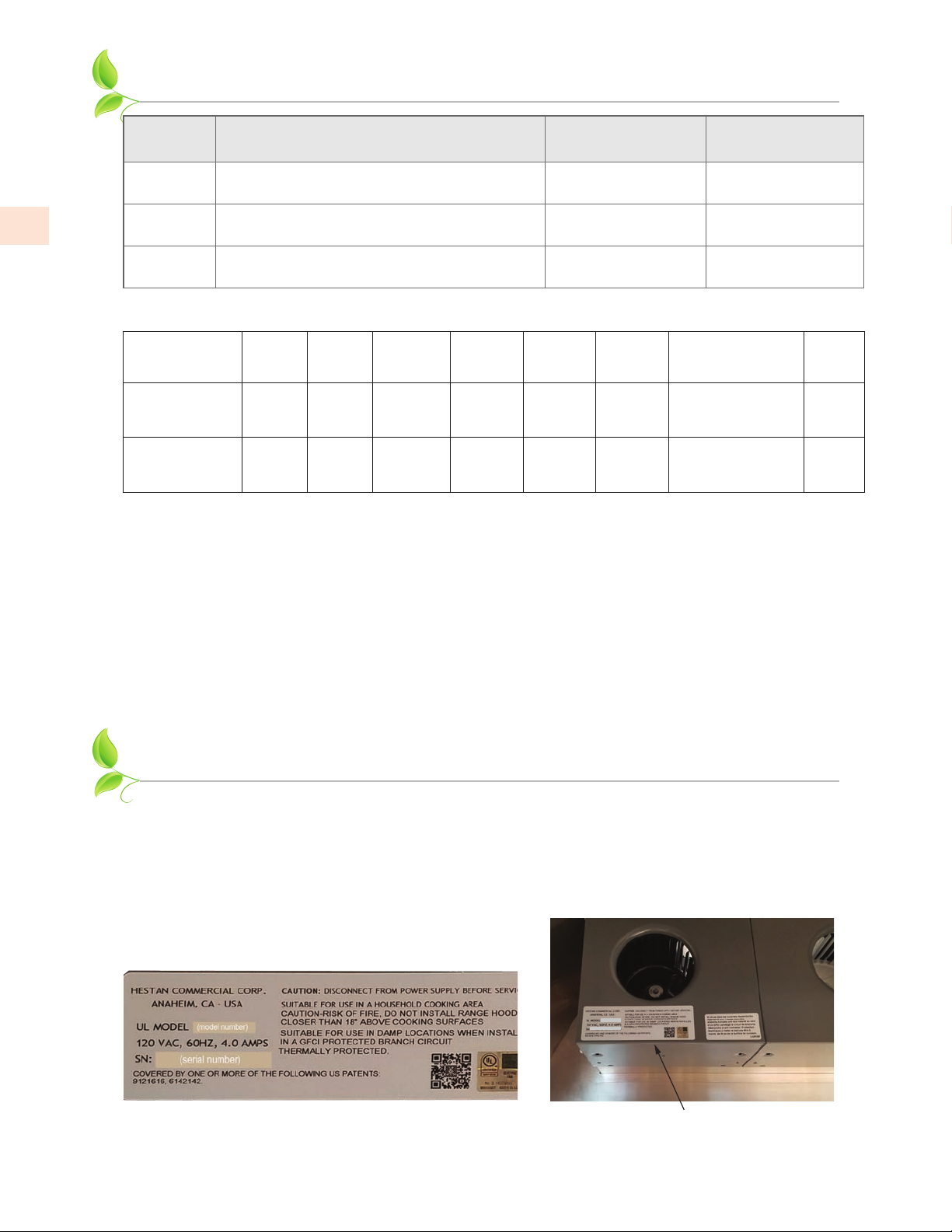
NUMÉROS DE MODÈLE
FR
NO.
MODÈLE
GVP42
GVP48
GVP54
DESCRIPTION
Système de Ventilation de Plein Air 900 CFM à style
Professionnel de 42 po [106,7 cm]
Système de Ventilation de Plein Air 1200 CFM à style
Professionnel de 48 po [121,9 cm]
Système de Ventilation de Plein Air 1200 CFM à style
Professionnel de 54 po [137,2 cm]
VENTILATEURS
UTILISÉS
WM2L double + WM1L
unique
WM2L ventilateur
double à deux
WM2L ventilateur
double à deux
RECOMMANDÉ
POUR LA GRIL
30 po
36 po
42 po
PUISSANCE ET FLUX D’AIR NOMINALPUISSANCE ET FLUX D’AIR NOMINAL
Paquet de
Ventilateur
WM2L double +
WM1L unique
WM2L
ventilateurs
double à deux
Ampéres
6,0 900 1350 804 725 655 AKVT6810:
7,5 1200 1800 1062 960 860 AKVT8812:
CFM
SP@0,0 *
Équivalent
CFM **
CFM
SP@0,1 *
CFM
SP@0,2 *
CFM
SP@0,3 *
Taille minimale du
conduit rond
10 po (79 po
[25,4 cm (509,7 cm2)]
12 po (113 po
[30,5 cm (729 cm2)]
2
)
2
)
Toutes les unités 115 VAC 60 Hz 1550 RPM [1 CFM = 1,7 m³/hr]
* Pression Statique en pouces de colonne d’eau.
** Lorsque vous comparez avec des unités soufflantes fabriquées par d’autres fabricants, utilisez le «équivalent CFM».
Sones
***
6,3
6,6
*** Cotes conformes au Standard Test Code du Energy Systems Laboratory de la Texas Engineering Experiment Station.
Le nombre indiqué correspond à la vitesse de ventilation la plus élevée.
PLAQUE SIGNALÉTIQUE
La plaque signalétique donne des informations importantes sur cet appareil Hestan telles que
le numéro de modèle et de série, les caractéristiques électriques et les dégagements minimum
d’installation.
La plaque signalétique se trouve sur le boîtier de soufflante.
Si un entretien est nécessaire, contactez le service clientèle de Hestan avec les informations sur le
modèle et le numéro de série figurant sur la plaque.
(model number)
(serial number)
Plaque signalétique typique
©2020 Hestan Commercial Corporation
4
Emplacement de la plaque
signalétique
Page 35
RESPECT DE LA RÉGLEMENTATION ET DES CODES EN VIGUEUR
L’installation de cet
locaux. En l’absence de tels codes, installer cet appareil conformément au National Electrical Code et
les codes locaux.
Tous les composants électriques doivent mis à la terre conformément aux codes locaux ou, en
l’absence de tels codes, au National Electrical Code
l’électricité du Canada
Système de Ventilation Plein Air
CSA C22.1.
doit être effectuée conformément aux codes
ANSI/NFPA 70
ou au Code national de
MODE D’EMPLOI
CARACTÉRISTIQUES DU SYSTÈME DE VENTILATIONCARACTÉRISTIQUES DU SYSTÈME DE VENTILATION
Des contrôles de vitesse sont fournis pour chaque ensemble de soufflante. Les systèmes à deux
soufflantes auront un bouton de contrôle de la vitesse, tandis que les systèmes à trois ou quatre
souffleries auront deux boutons de contrôle de la vitesse.
Un bouton de contrôle est fourni pour l’intensité de l’éclairage.
La disposition des commandes sera similaire à celle montrée ci-dessous.
UTILISATION DE LA HOTTEUTILISATION DE LA HOTTE
L’utilisateur peut commencer avec la hotte au réglage le plus bas, puis augmenter la vitesse et / ou
activer des ventilateurs supplémentaires au besoin. L’utilisation de la hotte à des réglages élevés peut
augmenter les exigences de chauffage ou de climatisation et les coûts pour la maison.
BOUTON DE COMMANDE DE VENTILATEURBOUTON DE COMMANDE DE VENTILATEUR
Pour faire fonctionner la (les) soufflante(s), faites tourner le bouton dans les réglages de vitesse du
ventilateur en le tournant dans le sens horaire (en faisant face au bouton).
FR
Tournez le bouton dans le sens anti-horaire pour réduire la vitesse du ventilateur.
BOUTON DE CONTRÔLE DE LA LUMIÈREBOUTON DE CONTRÔLE DE LA LUMIÈRE
Pour faire fonctionner les lumières, faites tourner le bouton à travers les réglages d’intensité
lumineuse en le tournant dans le sens horaire (en faisant face au bouton). Tournez la bouton dans le
sens anti-horaire pour atténuer les lumières ou les éteindre.
Commandes pour deux ventilateurs
1
Les contrôles pour trois et quatre ventilateurs
3
2
2
4
Article
Fonction
Contrôle du
1
ventilateur
Contrôle de la
2
lumière
Contrôle des
3
ventilateurs 1 et 2
Contrôle du
4
ventilateur 3 ou
des ventilateurs 3
et 4
©2020 Hestan Commercial Corporation
5
Page 36
FR
NETTOYAGE ET ENTRETIEN
NETTOYAGE DU SYSTÈME DE VENTILATIONNETTOYAGE DU SYSTÈME DE VENTILATION
Les exigences de nettoyage dépendent entièrement de l’utilisation et de l’environnement. Plus la
cuisson est chaude et /ou grasse, plus le hotte et le souffleur doivent être nettoyés.
Le bac à graisse et le soufflante ne sont pas visibles de l’extérieur, ils doivent donc être retirés pour
inspection.
Après avoir inspecté le bac plusieurs fois au cours de six mois ou d’un an, vous pouvez définir un
programme de nettoyage en fonction de votre mode d’utilisation.
LA HOTTELA HOTTE
Essuyez l’intérieur et l’extérieur de la hotte si nécessaire avec un chiffon doux et de l’eau chaude
savonneuse (un détergent à vaisselle liquide est acceptable). N’utilisez pas d’acides, d’abrasifs, de
détergents puissants, de solvants ou de tampons à récurer. L’acier inoxydable doit être traité avec un
nettoyant d’acier inoxydable de qualité tel que Stainless Steel Magic
de l’étiquette. Ne pas polir à travers le grain ou dans les cercles.
BOÎTIER ET BOUCLIERBOÎTIER ET BOUCLIER
Pour réduire le risque de blessure, assurez-vous que l’alimentation est
coupée dans l’appareil avant de retirer le(s) bouclier(s) et le s) boîtier (s)
de soufflante.
Le ventilateur capture les sous-produits de la graisse dans le(s) boîtier(s) de la soufflante et le(s)
bouclier(s) de la soufflante. Le(s) bouclier(s) nécessitent un nettoyage plus fréquent que le boîtier du
soufflante, mais la fréquence de cuisson détermine la fréquence à laquelle chaque élément doit être
nettoyé.
®
. Suivez toutes les instructions
Article Description
Boîtier de soufflante avec porte(s)
1
amortissante
Bouclier de soufflante
2
BOUCLIERBOUCLIER
Les boucliers sont facilement retirés pour le nettoyage en tirant le(s) bouclier(s) vers l’avant de la
hotte.
Veillez à maintenir le bac à niveau si la hotte a été récemment utilisée et si la graisse est
encore chaude.
Inspectez et nettoyez le bouclier. (Détails à suivre)
BOÎTIER DE SOUFFLANTEBOÎTIER DE SOUFFLANTE
Pour retirer le boîtier de la soufflante:
1. Déverrouillez deux loquets de valise, un de chaque côté du boîtier.
1
2
2. Soutenez le boîtier et retirez-le de la base du souffleur.
3. Tout en le tirant vers l’arrière, faites-le doucement basculer vers le bas pour dégager la (les)
roue(s) du souffleur.
©2020 Hestan Commercial Corporation
6
Page 37
2
NETTOYAGE ET ENTRETIEN
NETTOYAGENETTOYAGE
Nettoyez le(s) bouclier(s) et /ou le(s) boîtier(s) du soufflante dans un évier d’eau chaude savonneuse
(détergent à vaisselle liquide) et laissez tremper pendant quelques minutes. Laver avec une éponge
ou un torchon, rincer et laisser égoutter avant de réinstaller. Il est également possible de placer le(s)
boîtier(s) de la soufflante et le(s) bouclier(s) de la soufflante dans un lave-vaisselle. Manipulez les
volets en plastique du boîtier du soufflante avec précaution. Ils doivent se déplacer librement.
(SUITE)
2
3
4
1
FR
Article Description
Boîtier du moteur
1
Roue de soufflante
2
Boîtier de soufflante avec volets
3
Bouclier de soufflante
4
Pour réduire le risque de blessure, assurez-vous que l’alimentation est
coupée dans le hotte avant de retirer le(s) bouclier(s) et le(s) boîtier(s)
du soufflante.
Un nettoyage régulier du boîtier de la soufflante devrait empêcher l’accumulation de graisse sur
la roue de la soufflante. Si une accumulation de graisse se produit, la roue de la soufflante peut
facilement être nettoyée à l’aide d’une brosse à dents à poils doux et d’un dégraissant commun tel
que Formula 409
Article Description
Clip d’équilibrage
1
Roue de soufflante
2
®
.
Veillez à ne pas déplacer ou perdre les clips d’équilibrage en métal qui peuvent être
fixés à la roue.
1
©2020 Hestan Commercial Corporation
7
Page 38

NETTOYAGE ET ENTRETIEN
RETRAIT DE LA ROUERETRAIT DE LA ROUE
Pour les cas où la roue de soufflante doit être retirée, suivez les instructions ci-dessous.
• Le retrait de la roue de soufflante nécessite une clé hexagonale de 1/8 po. Ceci peut être obtenu
auprès de votre quincaillerie ou de votre fournisseur d’outils local.
(SUITE)
FR
La roue est retenue par une vis de réglage sur le côté du moyeu de la roue qui se resserre contre un
point «plat» sur l’arbre du moteur. (Voir l’illustration à la page précédente)
1. Localiser la vis de réglage sur le côté du moyeu de la roue.
2. Insérer une clé à travers les lames de la roue de ventilateur et dans la vis de réglage.
3. Desserrez la vis de réglage d’un demi-tour dans le sens anti-horaire.
Si la roue est difficile à enlever, la zone où l’arbre du moteur entre en contact avec le moyeu de la
roue de soufflante peut nécessiter une pulvérisation d’une huile pénétrante commune telle que
WD-40®.
Après avoir laissé tremper l’huile pénétrante pendant quelques minutes, poussez légèrement la
roue de la soufflante vers l’avant, puis retirez doucement la roue de la soufflante de l’arbre du
moteur.
• Faites attention à ne pas plier ou déformer la roue de la soufflante et veillez à ne pas déplacer ou
perdre les clips d’équilibrage métalliques qui peuvent être fixés sur la roue.
Une brosse à dents à poils doux et de l’eau chaude savonneuse peut être utilisée pour nettoyer les
lames ou faire tremper la roue de la soufflante dans de l’eau chaude savonneuse.
INSTALLATION DE LA ROUEINSTALLATION DE LA ROUE
Lors de la réinstallation de la roue sur l’arbre du moteur, assurez-vous que la vis de réglage est en
contact direct avec le «point plat» sur l’arbre du moteur.
1. Faites glisser la roue du ventilateur sur l’arbre du moteur aussi loin que possible, en vous assurant
que l’arrière de la roue du ventilateur ne touche pas les vis de montage du moteur qui dépassent
du moteur.
• Si le moteur est trop en arrière, il frottera les vis du support du moteur, et s’il est trop en avant, il
frottera l’intérieur du boîtier du ventilateur.
2. Ajustez légèrement la roue de la soufflante pour trouver l’emplacement correct de l’avant vers
l’arrière.
3. Serrez la vis de réglage (dans le sens des aiguilles d’une montre) pour verrouiller la roue du
ventilateur dans la bonne position.
Pour les hottes qui ont plus d’une roue de soufflante, assurez-vous que les roues blancs
sont assorties avec des anneaux de moteur blanc, et les roues noires sont assorties avec
des anneaux de moteur noir.
Le hotte de ventilation ne fonctionnera pas correctement si les roues du soufflante et les moteurs
sont incompatibles.
©2020 Hestan Commercial Corporation
8
Page 39
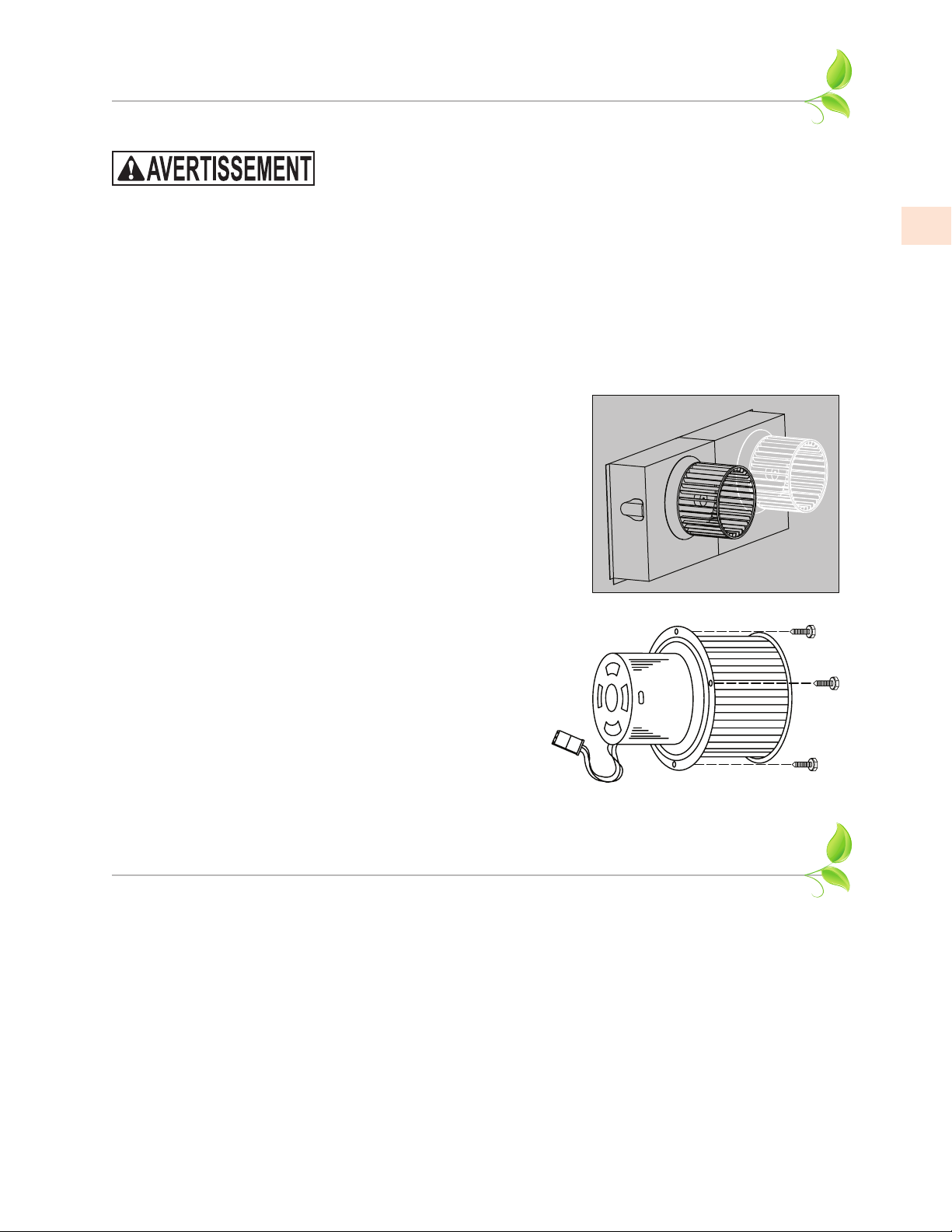
NETTOYAGE ET ENTRETIEN
(SUITE)
REMPLACEMENT DU MOTEUR REMPLACEMENT DU MOTEUR
Pour réduire le risque de blessure, coupez l’alimentation du disjoncteur
ou du disjoncteur avant d’essayer de retirer le moteur de la soufflante.
IDENTIFICATION ET POSITIONNEMENT DU MOTEURIDENTIFICATION ET POSITIONNEMENT DU MOTEUR
Les moteurs sont codés par couleur. Les moteurs noir et blanc ont des rotations différentes et
doivent être installés dans les bonnes positions.
• Les boîtiers avec une seule soufflante utilisent un roue blanc.
• Les boîtiers avec deux soufflante utilisent une roue blanc sur la droite et noire sur la gauche.
Assurez-vous d’avoir le bon moteur dans chaque position du boîtier.
• Si le moteur de soufflante de remplacement comprend une roue de soufflante, vous pouvez
retirer le moteur et la roue ensemble. Si vous réutilisez votre roue existante, vous pouvez retirer
la roue avant de retirer le moteur.
1. Retirez le bouclier et le boîtier de la soufflerie comme
décrit dans «RETRAIT DE LA ROUE» à la page 8.
2. Utilisez un tourne-écrou ¼ po pour retirer les trois vis du
support moteur qui fixent le moteur à la base.
FR
3. Tirez doucement le moteur vers l’avant et vers le bas.
4. Débranchez le faisceau de câblage, retirez l’ancien moteur.
• Pour éviter d’endommager la roue de soufflante, vous
pouvez installer le moteur, puis installer la roue sur le
moteur.
5. Soulevez le nouveau moteur pour pouvoir connecter le
faisceau de câblage. Assurez-vous de bien engager les
connexions électriques et serrez les vis de fixation du
moteur.
6. Vérifiez le jeu des roues de la soufflerie et réglez au
besoin, comme décrit dans «INSTALLATION DE LA
ROUE» à la page8.
DÉPANNAGE
Si la hotte ne fonctionne pas de manière satisfaisante, vérifiez les points suivants:
• Est-ce que les soufflantes courent?
• Les roues de la soufflante sont-elles installées sur les bons moteurs? (roue noir sur le moteur noir,
roue blanc sur le moteur blanc)
• Les ensembles moteur et roue sont-ils installés aux bons emplacements?
• Vérifiez les portes d’amortissement dans le boîtier du soufflante - bougent-ils / s’ouvrent-ils
librement?
• Vérifiez les registres / évents à l’extérieur - ouvrent-ils librement, sans obstacles?
• Vérifiez s’il y a des conduits endommagés ou obstrués.
©2020 Hestan Commercial Corporation
9
Page 40

FR
BONNE PRATIQUE DE CANALISATION
EXIGENCES GÉNÉRALESEXIGENCES GÉNÉRALES
Respectez les codes locaux en ce qui concerne les exigences de conduits spéciaux et le placement du
conduit contre les combustibles.
• L’utilisation des transitions recommandées (voir ACCESSOIRES DE VENTILATION) garantira
une efficacité adéquate.
• L’utilisation des chapeaux de toit ou des évents murales recommandés (voir ACCESSOIRES DE
VENTILATION) garantira une efficacité adéquate.
• Utilisez du ruban adhésif HVAC métallique (pas de ruban adhésif en toile grise) pour sceller tous
les joints.
• La hotte doit être canalisée vers l’extérieur sans restriction.
EXIGENCES DE SOUFFLEUREXIGENCES DE SOUFFLEUR
Le ventilateur double (WM2L, utilisé dans tous les systèmes) nécessite un conduit rond de 8 po [20,3
cm] ou équivalent (50 po² - 323 cm²). Le ventilateur simple (WM1L, utilisé dans les systèmes 900
CFM) nécessite un conduit rond de 6po ou équivalent (28 po² - 181 cm²).
TAILLE DE CONDUIT COMBINÉE APRÈS UNE TRANSITIONTAILLE DE CONDUIT COMBINÉE APRÈS UNE TRANSITION
Simple et double (WM1L et WM2L) combinent à 10 po [25,4 cm] rond ou équivalent 79 po² [509,7
cm²] en utilisant une transition multi-soufflante telle que AKVT6810 (optionnel).
Doubles à deux (deux WM2L) se combinent à 12 po [30,5 cm] rond ou équivalent 113 po² [729 cm²]
en utilisant une transition multi-soufflante telle que AKVT8812 (optionnel).
EXIGENCES DE CANALISATION (BONNE PRATIQUE DE CANALISATION)EXIGENCES DE CANALISATION (BONNE PRATIQUE DE CANALISATION)
• NE JAMAIS réduire la taille du conduit. Lors de la combinaison de conduits, la surface en
pouces carrés du conduit de sortie doit être égale ou supérieure à la surface totale en pouces des
conduits combinés.
• Utiliser seulement des conduits métalliques lisses et galvanisés. N’utilisez pas de conduit flexible
ou ondulé. Ce type de conduit limitera le flux d’air et réduira les performances.
• Faire le chemin le plus court possible et aussi droit que possible avec aussi peu de tours que
possible.
• Évitez les virages serrés. Au lieu de cela, utilisez des virages lisses et progressifs tels que les
coudes réglables ou les virages angulaires de 45 degrés.
• Pour les conduits de plus de 20 pieds [6 m], augmentez le diamètre du conduit d’un pouce [2,5
cm] pour chaque 10 pieds [3 m] de conduit.
• Lors de la planification de la longueur, du conduit, un coude de 90 degrés est équivalent à 5 pieds
[1,5 m] de conduit.
CONDITIONS DE TÉRMINAISION CONDITIONS DE TÉRMINAISION
Le flux d’air ne doit pas être limité à la fin
du parcours du conduit.
Un évent mural ou un chapeau de toit est
OUI
requis pour chaque passage de conduit.
Chaque évent mural ou un chapeau de toit
doit inclure un amortisseur à gravité pour
Conduit lisse Virage progressif lisse
Bonne combinaison
de deux conduits
éviter les retours d’air.
10
N’utilisez pas de moustiquaires ou de portes
à ressort sur les évents murales ou les
chapots de toit.
Ne pas terminer l’évacuation dans un
grenier ou une cheminée.
©2020 Hestan Commercial Corporation
NON
Conduit flexible
Virages angulaires
aiguisés
Mauvaise combinaison
de deux conduits
Page 41

INSTALLATION
POUR RÉDUIRE LES RISQUES D’INCENDIE, DE CHOC
ÉLECTRIQUE OU DE BLESSURE, OBSERVEZ CE QUI SUIT:
a) Les travaux d’installation et de câblage électrique doivent être effectués par des personnes
qualifiées conformément à tous les codes et normes applicables, y compris la construction
résistante au feu.
b) Une quantité suffisante d’air est nécessaire pour assurer une combustion et une évacuation
correctes des gaz à travers la cheminée de l’équipement de combustion du carburant afin d’éviter
le retour de courant. Suivez les directives du fabricant de l’équipement de chauffage et les
normes de sécurité telles que celles publiées par l’Association nationale de protection contre
les incendies (NFPA), et l’American Society for Heating, Refrigeration and Air Conditioning
Engineers (ASHRAE) et les autorités locales.
c) Lors de la coupe ou du perçage dans le mur ou le plafond, ne pas endommager le câblage
électrique et les autres services publics cachés.
d) Les ventilateurs canalisés doivent toujours être ventilés vers l’extérieur.
POUR RÉDUIRE LE RISQUE D’INCENDIE, UTILISEZ UNIQUEMENT
DES CONDUITS MÉTALLIQUES.
POUR RÉDUIRE LE RISQUE D’INCENDIE OU D’ÉLECTROCUTION, NE PAS UTILISER CE
VENTILATEUR AVEC UN DISPOSITIF DE COMMANDE DE VITESSE À L’ÉTAT SOLIDE.
FR
DÉTAILS D’INSTALLATIONDÉTAILS D’INSTALLATION
Lisez attentivement toutes les instructions avant de commencer l’installation. Remarque: Ces
instructions s’appliquent uniquement aux hottes de plein air Hestan, lorsqu’elles sont montées sur
un gril Hestan ou Aspire. VOUS DEVEZ SUIVRE LES DÉGAGEMENTS DU GRIL DÉCRITS DANS
VOTRE MANUEL D’INSTALLATION DU GRIL.
POUR LES EMPLACEMENTS NON-COMBUSTIBLES SEULEMENT !! Cet appareil est fixé
au mur et ne doit PAS être installé sur ou à proximité d’une construction combustible non
protégée. Un dégagement minimum par rapport aux matériaux combustibles verticaux, tels
que les murs adjacents, est de 12 po [30 cm] sur les côtés de l’appareil (Voir fig. 1).
TOUS les matériaux de construction dans le mur immédiatement derrière de la hotte et l’appareil
en dessous (généralement un gril), ainsi que dans la zone de 12 po [30 cm] doivent être noncombustibles. Si par exemple, si vous avez une surface en stuc ou en carrelage et une construction
à ossature de bois en dessous, ou des murs à ossature de bois adjacents ou à l’arrière, le bois
est considéré comme combustible, même si la hotte ou le gril touche le stuc ou la surface en
carrelage non-combustible. Dans des circonstances extrêmes, le bois peut potentiellement devenir
suffisamment chaud pour brûler.
De même, si la hotte est montée sur une gril autoportante garée près de ces surfaces lors de la cuisson
sur une longue période, une quantité de chaleur radiante suffisante peut atteindre le bois et devenir
suffisamment chaude pour brûler, dans des circonstances extrêmes.
Les matériaux de construction tels que les colombages métalliques avec des panneaux de ciment et
les surfaces en stuc / pierre sont idéaux pour cette application.
Un dégagement minimum de 5 po [12,7 cm] derrière le gril est nécessaire pour ouvrir la couvercle du
gril et capter correctement la fumée et les vapeurs de la zone de cuisson.
Voir la Fig. 1 à la page suivante pour plus de détails.
©2020 Hestan Commercial Corporation
11
Page 42
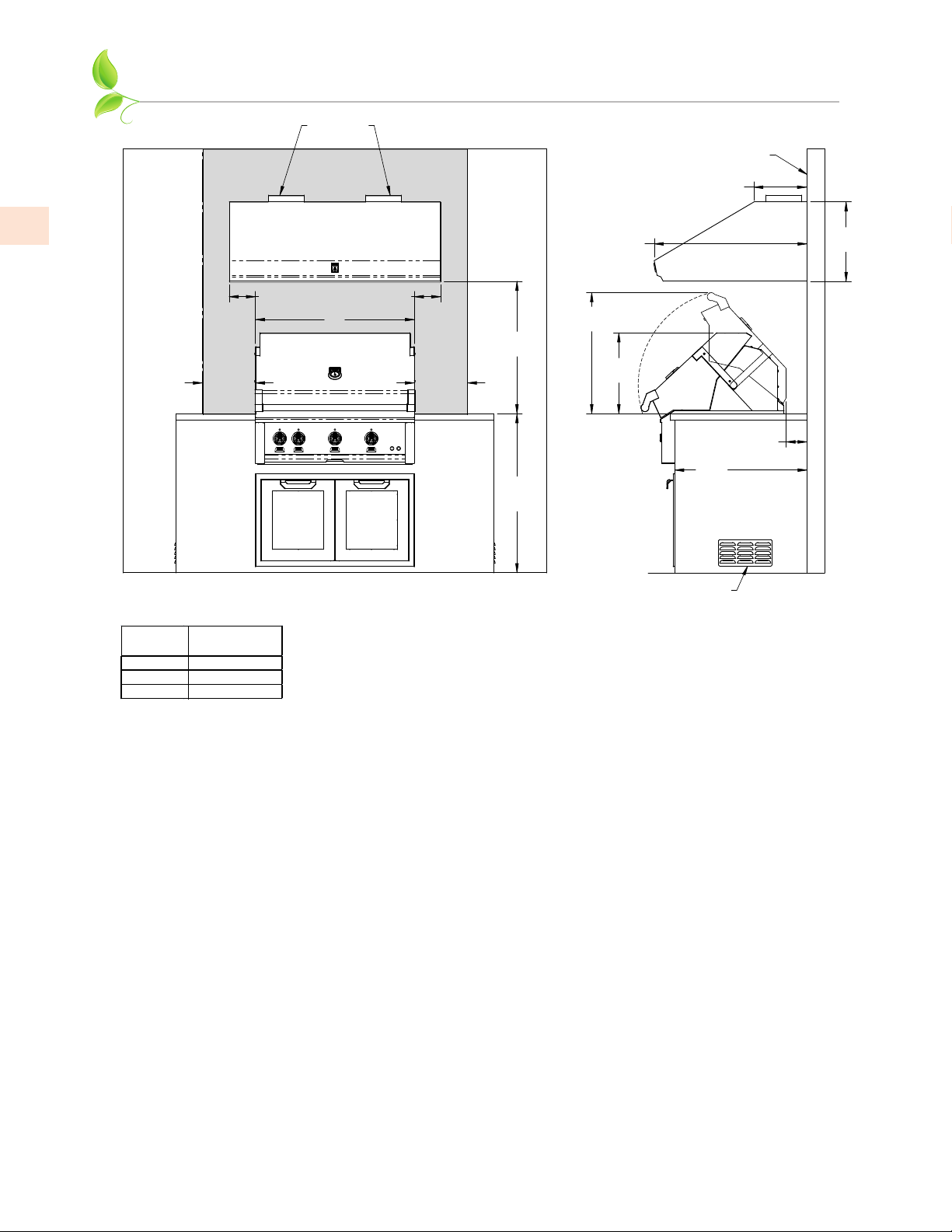
LARGEUR
HOTTE
42 po [106,7]
GVP54
INSTALLATION
(SUITE)
SORTIE
DU CONDUIT
CONSTRUCTION
NON-COMBUSTIBLE
12 po
[30,5]
FR
34,6 po
[87,9]
6 po
[15,1]
W
12 po
[30,5]
NOTES:
* LES ZONES OMBRÉES INDIQUENT LES ENDROITS OÙ LES MATÉRIAUX COMBUSTIBLES SON PROHIBÉS.
* «W» INDIQUE LA LARGEUR DU GRIL.
DU GRIL
30 po [76,2]
36 po [91,4]
RECOMMANDÉ
GVP42
GVP48
6 po
[15,1]
12 po
[30,5]
30 po
[76,2]
36 po
[91,4]
REF.
27,4 po
[69,7]
18,3 po
[46,5]
CONSTRUCTION NON-COMBUSTIBLE SEULEMENT
(GRIL HESTAN REPRÉSENTÉ)
30 po
[76,2]
REF.
OUÏE D’AERATION
5 po
[12,3]
MIN.
18 po
[45,7]
Fig. 1
1. Lisez attentivement toutes les instructions avant de commencer l’installation. Voir «BONNE
PRATIQUE DE CANALISATION» à la page 10.
• Poids et taille: Pour une installation en toute sécurité, au moins deux personnes doivent être
présentes pour soulever et maintenir le hotte. Pour les grandes hottes et les installations avec des
couvercles de conduit, il est conseillé d’avoir une troisième personne présente pour aider.
• Évacuation arrière: Si vous évacuez par le mur arrière au lieu de traverser le plafond, consultez la
section «VENTILATION ARRIÈRE» à la page 18 pour plus de détails.
2. Lors de l’installation d’une hotte murale, il est recommandé que le bord inférieur de la hotte ne
soit pas situé à plus de 30 po [76,2 cm] au-dessus de la surface de cuisson pour une performance
optimale.
3. La séquence de câblage et la préparation des conduits varient en fonction de l’accès au sommet
de la hotte après l’installation. Sélectionnez la méthode d’installation appropriée:
Méthode 1: est adaptée aux applications où le haut de la hotte (sortie du ventilateur) est
accessible après le montage de la hotte sur le mur et lorsqu’un cache-conduit Hestan sera
utilisé.
• REMARQUE: Comme la cache-conduit Hestan peuvent être ouverts pour l’accès, ils peuvent
être installés avec la hotte tout en permettant l’accès aux points de connexion. Le cadre de la
cache-conduit exige que le hotte et la cache-conduit soient installés ensemble.
Méthode 2: est adaptée aux applications où le haut de la hotte (sortie du ventilateur) n’est pas
accessible après le montage de la hotte sur le mur.
12
©2020 Hestan Commercial Corporation
Page 43
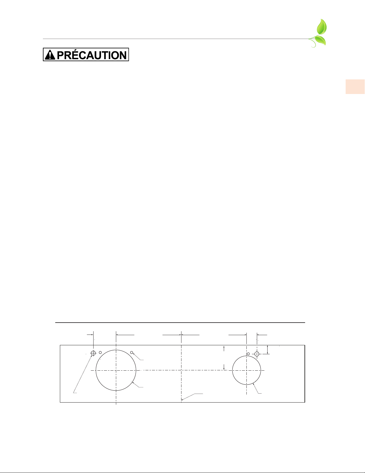
WM2L Double Soufflante + WM1L Soufflante Simple (900 CFM)
(Côté du Mur)
Schéma de Connexion 42 po [106,7 cm] de largeur
INSTALLATION
(SUITE)
Assurez-vous qu’une fois la hotte installée, les ouvertures d’aeration
du moteur ne sont pas obstrués.
4. SI LA HOTTE DOIT ÊTRE «VENTILÉE À L’ARRIÈRE», PASSEZ DIRECTEMENT À L’ÉTAPE 5.
Consultez les schémas de raccordement (ci-dessous) pour plus de détails sur le placement de les
sorties du ventilateur.
Méthode 1: Installez les conduits de l’extérieur de la maison à l’emplacement de la sortie du
ventilateur au-dessus de la hotte ou à la transition (si utilisée).
• Si une transition est utilisée, installez le conduit à l’emplacement de la sortie de transition
plus 1 po [2,5 cm]. Cela permettra à la transition de s’engager 1 po [2,5 cm] à l’intérieur du
conduit.
Méthode 2: Installez le conduit(s) de l’extérieur de la maison au plafond sur les sorties du
ventilateur sur le hotte. L’extrémité du(des) conduit(s) doit dépasser de 1 po [2,5 cm] sous
le plafond.
• Utilisez du ruban adhésif HVAC métallique (pas de ruban adhésif en toile grise) pour sceller
tous les joints. Voir «ACCESSOIRES DE VENTILATION» à la page20 pour plus de détails.
HAUTEURS DE TRANSITIONHAUTEURS DE TRANSITION
Soufflante Simple et Double (WM1L + WM2L = 900 CFM): Une conduit ronde de 6 po [15,2
cm] se raccordera directement au haut de la hotte. Le conduit rond de 8 po [20,3 cm] se
raccordera directement au haut de la hotte. Si vous utilisez la transition AKVT6810 en
option (vendu séparément), un conduit rond de 10 po [25,4 cm] est connecté à celle-ci à
17-1/2 po [44,4 cm] au-dessus de la hotte. Voir «ACCESSOIRES DE VENTILATION» à la
page20 pour plus de détails.
FR
Deux Soufflantes Doubles (deux WM2L = 1200 CFM): Deux conduits ronds de 8 po [20,3
cm] se connecte directement à chaque sortie du soufflante. Si vous utilisez la transition
AKVT8812 en option (vendu séparément), un conduit rond de 12 po [30,5 cm] est raccordé
à cette sortie 16-1/2 po [41,9 cm] au-dessus de la hotte. Voir «ACCESSOIRES DE
VENTILATION» à la page20 pour plus de détails.
DIAGRAMMES DE CONNEXION DIAGRAMMES DE CONNEXION
5-1/2 po
[14 cm]
7-5/16 po
[18,6 cm]
Ouverture
d’ Aération
du Moteur (3)
7-5/16 po
[18,6 cm]
5-1/4 po
[13,3 cm]
1-7/8 po
[4,8 cm]
1-3/4 po
[4,4 cm]
Électrique (2)
8 po [20,3 cm]
Rond
Ligne centrale
du Hotte
6 po [15,2 cm]
Rond
(Vue de Dessus)
©2020 Hestan Commercial Corporation
13
Page 44
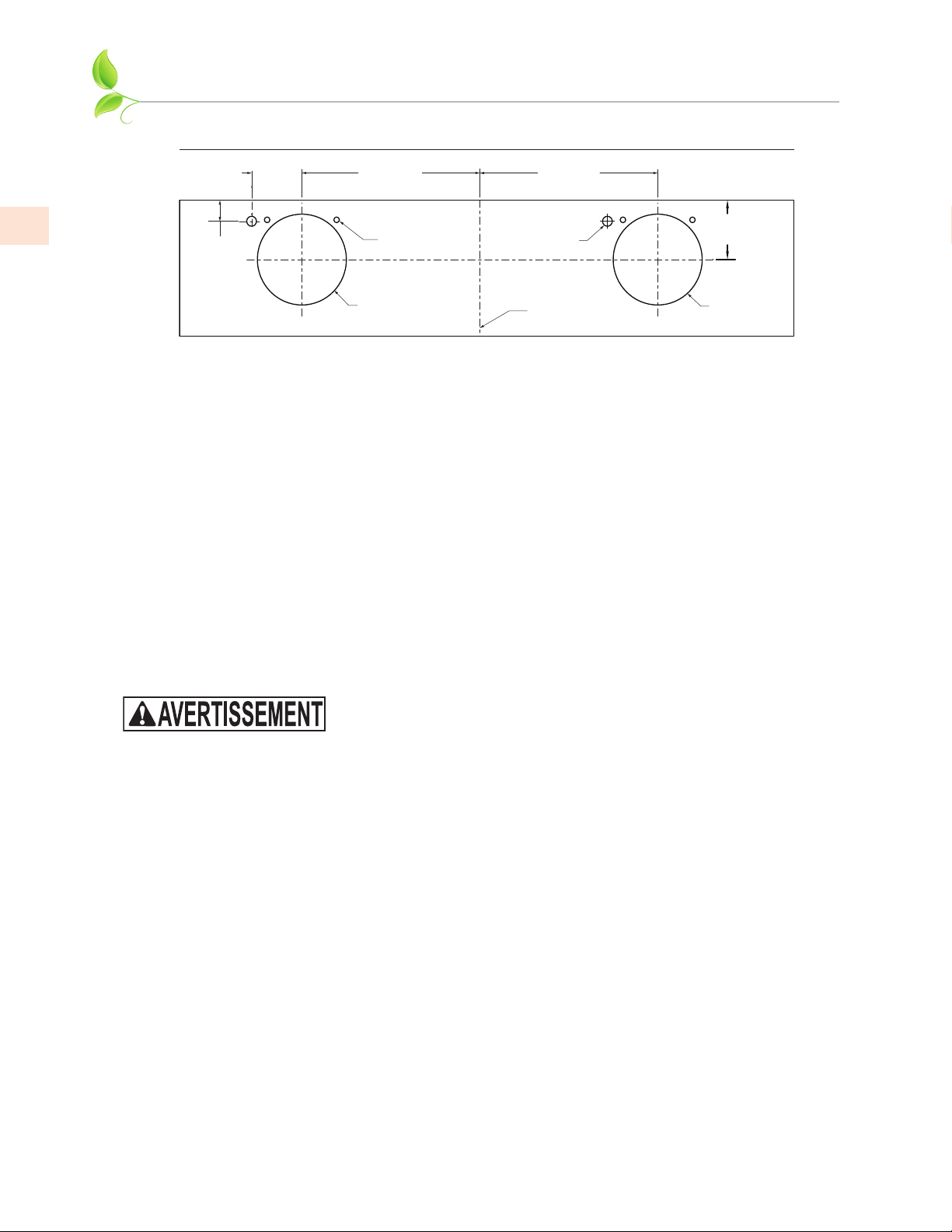
Deux WM2L Double Soufflantes (1200 CFM)
Schéma de Connexion 48-54 po [121,9-137,2 cm] de largeur
INSTALLATION
(SUITE)
FR
1-3/4 po
[4,4 cm]
5-1/2 po
[14 cm]
11 po
[29,9 cm]
Ouverture
d’ Aération
du Moteur (2)
8 po [20,3 cm]
Rond
11 po
[29,9 cm]
Électrique (2)
Ligne centrale
du Hotte
(Côté du Mur)
5-1/4 po
[13,3 cm]
8 po [20,3 cm]
Rond
(Vue de Dessus)
5. Retirez la hotte de son emballage et placez l’arrière de la hotte sur le sol ou sur le comptoir
devant le mur où il sera accroché.
6. Avec l’unité sur le dos face à vous, retirez le(s) boîtier(s) et le(s) bouclier(s) de la ventilateur
comme suit:
a) Retirez le ruban d’expédition qui attache le(s) bouclier(s) de la soufflante à l’intérieur de la
hotte.
b) Retirez le(s) bouclier(s) en le tirant légèrement vers l’avant de la hotte.
c) Fermez doucement le(s)
porte(s) amortissante
du côté supérieur de la hotte.
d) Pour retirer le(s) boîtier(s) de la soufflante, déverrouillez les loquets de la valise (un de
chaque côté du boîtier).
e) Soutenez le boîtier et soulevez-le pour l’éloigner de la base du ventilateur, puis renversez-le
pour dégager les roues du ventilateur, puis retirez-le du hotte.
Assurez-vous que le panneau d’alimentation / disjoncteur est hors
tension pendant le service ou l’installation.
7. Un moteur de soufflante doit être retiré de chaque ensemble de soufflante pour accéder à la
(aux) boîte(s) de connexion. L’ensemble de la soufflante aura une décalcomanie identifiant
l’emplacement de la ou des boîtes de connexion. Il n’est pas nécessaire d’enlever la roue de
soufflante du moteur.
a) Retirez les trois vis retenant le moteur de la soufflante.
b) Tirez le moteur suffisamment loin pour pouvoir atteindre son connecteur électrique
c) Débrancher le connecteur, mettre le moteur de la soufflante et les vis de côté.
8. PRÉPARATION DU CÂBLAGE:
a) Installez une pince électrique de 1/2 po homologuée UL dans chaque ouverture électrique
de la boîte à moteur sur le dessus de la hotte.
b) Installez le câblage électrique du panneau de service à l’emplacement de la hotte pour
chaque boîte à moteur. Consultez les schémas de connexion (sur la page précédente) pour
plus de détails. Voir «ALIMENTATION ÉLECTRIQUE ET MISE A LA TERRE» à la page1
pour les exigences d’alimentation.
Méthode 1: Étendre le câblage à 30 po [76,2 cm] au-dessus du comptoir. Les connexions
électriques se produiront après l’installation de la hotte sur le mur.
Méthode 2: Étendre le câblage à la hotte. Des connexions électriques se produiront avant
que la hotte ne soit installée sur le mur.
14
©2020 Hestan Commercial Corporation
Page 45

INSTALLATION
9. Marquez le mur sur le bord inférieur de l’ouverture de la hotte.
a) Si vous utilisez une cache-conduit Hestan:
i. Retirez délicatement les débouchures des quatre coins supérieurs de la hotte.
(SUITE)
ii. Retirez la cache-conduit de son emballage et retirez les vis de montage de la base.
iii. Placez la cache-conduit sur le dessus de la hotte et fixez-le temporairement à travers les
ouvertures défonçables à l’aide des vis de montage retirées précédemment.
• Le panneau avant peut être retiré de la cache-conduit pendant la manipulation pour
réduire le poids.
b) Soulevez la hotte (et l’ensemble de cache-conduit si utilisé) à l’endroit sur le mur où il sera
installé.
c) Marquer légèrement le mur avec une marque horizontale courte le long du bord inférieur de
la hotte.
d) Lorsque vous avez terminé, retirez la hotte et l’ensemble de la cache-conduit du mur.
10. Trouver l’emplacement de la bande de montage:
a) À l’arrière de la hotte, mesurez la distance entre le bord inférieur de la hotte et le bord
supérieur de la bande de fixation en bois.
b) Mesurez cette distance au-dessus de la marque horizontale faite à l’étape 9 et marquez
légèrement le mur avec une ligne horizontale et horizontale.
c) Mesurez où se trouve le centre (gauche à droite) de la hotte et marquez la ligne horizontale
supérieure sur le mur avec une ligne centrale verticale courte.
11. Fixez la bande de montage au mur comme suit:
a) Retirez les vis à l’intérieur du haut de l’arrière de la hotte qui retiennent la bande de bois qui
est encastrée dans le canal de montage. Remarque: Certaines vis de fixation peuvent être
situées derrière a les soufflantes.
FR
b) Retirez la bande de fixation en bois de l’arrière de la hotte et placez le bord supérieur de la
bande sur la ligne horizontale supérieure et horizontale du mur.
c) En vous référant à la ligne centrale verticale de l’étape 10, placez la bande de montage sur
le mur de manière à ce qu’elle soit centrée (de gauche à droite) dans l’espace où sera située
la hotte. Marquer la bande à deux endroits ou plus, et percer des trous dans la bande pour
éviter le fendillement.
d) À l’aide du matériel approprié, fixez la bande de montage à au moins deux montants
muraux. Remarque: pour les hottes de 48 po [122 cm] et plus, trois vis dans les colombages
sont recommandées.
12. POUR LES APPLICATIONS DE VENTILATION ARRIÈRE SEULEMENT. SI PAS DE
VENTILATION ARRIÈRE, PASSEZ DIRECTEMENT À L’ÉTAPE 13.
• Remarque: Les colombages de paroi peuvent interférer avec les installations de ventilation arrière.
Un encadrement supplémentaire peut être requis. Il est nécessaire de couper le(s) trou(s) d’accès
au conduit dans le mur avant d’installer la hotte.
• Si vous utilisez une cache-conduit, cette étape peut être faite avec le cache-conduit retiré de la
hotte. Le cache-conduit doit toujours être monté sur le hotte avant de monter le hotte sur le
mur.
©2020 Hestan Commercial Corporation
15
Page 46

FR
INSTALLATION
Méthode 1:
a) Tenez le hotte sur la bande de montage en alignant le canal au sommet de l’arrière de la
hotte sur la bande de fixation en bois sur le mur.
b) Placez le(s) coude(s) approprié(s) sur le dessus de la hotte en ligne avec le(s) collier(s) de
sortie de la hotte. Sur le mur, tracez autour du coude(s). Retirez le hotte et les coudes du
mur.
c) Couper autour de l’extérieur de la ligne tracée, en évitant les colombages de paroi.
Installez le conduit de l’extérieur de la maison à l’ouverture dans le mur. Utilisez du ruban
HVAC métallique (pas de ruban adhésif en toile grise) pour sceller les joints.
d) Passez à l’étape 14.
Méthode 2:
a) Utilisez les schémas de connexion ( à la page13), «VENTILATION ARRIÈRE» à la
page18 et «ACCESSOIRES DE VENTILATION» à la page20 comme guide. Installez
le(s) conduit(s) de l’extérieur de la maison au mur de façon à ce qu’ils rencontrent les
coudes d’échappement à utiliser.
b) L’extrémité du (des) conduit(s) doit dépasser de 1 po [2,5 cm] les extrémités des coudes.
c) Passez à l’étape 14.
(SUITE)
13. Vérifiez les trous de montage sur la bande de bois, percez si nécessaire:
a) Accrochez le hotte sur la bande de montage en alignant le canal au sommet de l’arrière de
la hotte sur la bande de montage en bois sur le mur.
b) Tout en maintenant la hotte en place, déterminez si les trous de montage dans le canal en
haut de l’arrière de la hotte sont alignés avec les trous existants dans la bande de montage.
Si ce n’est pas le cas, marquez l’emplacement des trous sur la bande de montage.
c) Enlevez la hotte et percez avec un mèche de 3/32 po [2,5 mm] au centre des marques dans
la bande de montage en bois, pour éviter le fendillement.
14. MONTAGE DE LA HOTTE:
POUR LES APPLICATIONS DE VENTILATION ARRIÈRE SEULEMENT. SI PAS DE
VENTILATION ARRIÈRE, PASSEZ À L’ÉTAPE 15.
Si vous utilisez un cache-conduit Hestan, il doit être monté sur la hotte à l’aide des fixations
fournies avant de continuer.
Méthode 1:
a) Placez le(s) coude(s) approprié(s) sur le dessus de la hotte. Les coudes doivent être placés
avec la (les) extrémité(s) non sertie(s) à l’intérieur du (des) collet(s) de la (des) sortie(s) de la
ventilateur. Utilisez du ruban HVAC métallique (pas de ruban adhésif en toile grise) pour
sceller les joints.
b) Soulevez le hotte vers le mur et accrochez le hotte sur la bande de montage, en veillant à
aligner correctement le(s) raccord(s) de conduit(s) entre le(s) coude(s) et le(s) conduit (s) du
mur.
16
c) Fixez le hotte à la bande de montage en installant les vis (préalablement retirées de la bande
à l’étape 11) dans les trous de guidage percés à l’étape 13.
• Des précautions doivent être prises pour éviter de rayer le hotte ou le plafond.
©2020 Hestan Commercial Corporation
Page 47

INSTALLATION
Méthode 2:
a) Placez le(s) coude(s) approprié(s) sur le dessus de la hotte. Les coudes doivent être placés
avec la (les) extrémité(s) non sertie(s) à l’intérieur du (des) collet(s) de la (des) sortie(s) de la
ventilateur. Utilisez du ruban HVAC métallique (pas de ruban adhésif en toile grise) pour
sceller les joints.
b) Insérez le fil électrique du panneau de service dans le serre-fils électrique de chaque boîte à
moteur. Serrez la serre-câble.
c) Tout en fixant le mou dans le fil, soulevez le hotte vers le mur et accrochez le hotte sur la
bande de montage, en veillant à bien aligner le(s) raccord(s) du conduit entre le(s) coude(s)
et le conduit(s) dans le mur.
d) Fixez le hotte à la bande de montage en installant les vis (préalablement retirées de la bande
à l’étape 11) dans les trous de guidage percés à l’étape 13.
SI LA VENTILATION À L’ARRIÈRE, PASSEZ L’ÉTAPE 15. PASSEZ DIRECTEMENT À L’ÉTAPE 16.
15. MONTER LA HOTTE, SANS VENTILER À L’ARRIÈRE
Si vous utilisez une transition, installez-la à l’intérieur des colliers de sortie et scellez-la avec du
ruban HVAC métallique (pas avec du ruban adhésif en toile gris). Montez ensuite le hotte comme
suit:
Méthode 1:
(SUITE)
FR
a) Soulevez le hotte (et le cache-conduit, le cas échéant) jusqu’au mur et suspendez le hotte
sur la bande de montage, en veillant à aligner correctement le(s) raccord(s) de conduit
entre le hotte et le conduit dans le plafond.
b) Fixez le hotte à la bande de montage en installant les vis (préalablement retirées de la
bande à l’étape 11) dans les trous de guidage percés à l’étape 13.
c) Utilisez du ruban HVAC métallique (pas de ruban adhésif en toile grise) pour sceller les
joints. Insérez le fil électrique du panneau de service dans la pince de fil électrique sur
chaque boîte de moteur.
d) Serrez la serre-câble.
Méthode 2:
a) Insérez le fil électrique du panneau de service dans le serre-câble électrique de chaque
boîte à moteur. Serrez la serre-câble.
b) Si vous n’utilisez pas de transition, coupez un morceau de conduit pour chaque sortie
d’une longueur suffisante pour le(s) conduit(s) au plafond.
c) Si une transition est utilisée, coupez le conduit pour atteindre la sortie de transition plus
1 po [2,5 cm]. Cela permettra à la transition de s’engager 1 po [2,5 cm] à l’intérieur du
conduit. Voir «HAUTEURS DE TRANSITION» à la page13.
d) Une extrémité du conduit doit être sertie pour s’adapter à l’intérieur du conduit dans le
plafond. Insérez l’extrémité non sertie sur la transition ou dans le(s) collier(s) de sortie sur
le dessus de la hotte et scellez avec ruban HVAC métallique (pas de ruban de toile grise).
e) Tout en sécurisant le mou dans le câble, soulevez le hotte vers le mur et accrochez le hotte
sur la bande de montage, en veillant à aligner correctement le(s) raccord(s) de conduit
entre le hotte et le conduit dans le plafond.
f) Fixez le hotte à la bande de montage en installant les vis (préalablement retirées de la
bande à l’étape 11) dans les trous de guidage percés à l’étape 13.
©2020 Hestan Commercial Corporation
17
Page 48

FR
INSTALLATION
16. Si un cache-conduit Hestan est utilisé, il doit être fixé à au moins un montant à l’aide des bandes
de clouage. Le panneau avant du cache-conduit doit alors être installé.
17. CONNEXION DU CÂBLAGE:
À l’intérieur de la hotte, à l’aide des écrous de câblage homologués UL, fixez les fils «neutres» aux
fils blancs, les fils «chauds» aux fils noir , et le fil de terre à la fil verte à l’intérieur de la (des)
boîte(s) du moteur(s).
18. Branchez le(s) moteur(s) dans la hotte et réinstallez le(s) moteur(s) de la soufflante en utilisant les
trois vis de fixation qui ont été précédemment retirées à l’étape 7.
• Assurez-vous que les moteurs sont installés aux emplacements appropriés. Voir
«IDENTIFICATION ET POSITIONNEMENT DU MOTEUR» à la page9.
19. Replacez le(s) boîtier(s) de la soufflante et le(s) bouclier(s) de soufflante. Assurez-vous que la ou
les portes d’amortissement s’ouvrent et se ferment librement.
20. Mettre l’appareil sous tension, vérifier le fonctionnement: Voir «MODE D’EMPLOI» à la page5
pour le bon fonctionnement de la hotte. Testez toutes les fonctions de soufflerie et d’éclairage
pour vous assurer qu’elles fonctionnent correctement.
(SUITE)
NE PAS UTILISER LA HOTTE SANS UNE MISE À LA TERRE
APPROPRIÉE.
18
©2020 Hestan Commercial Corporation
Page 49
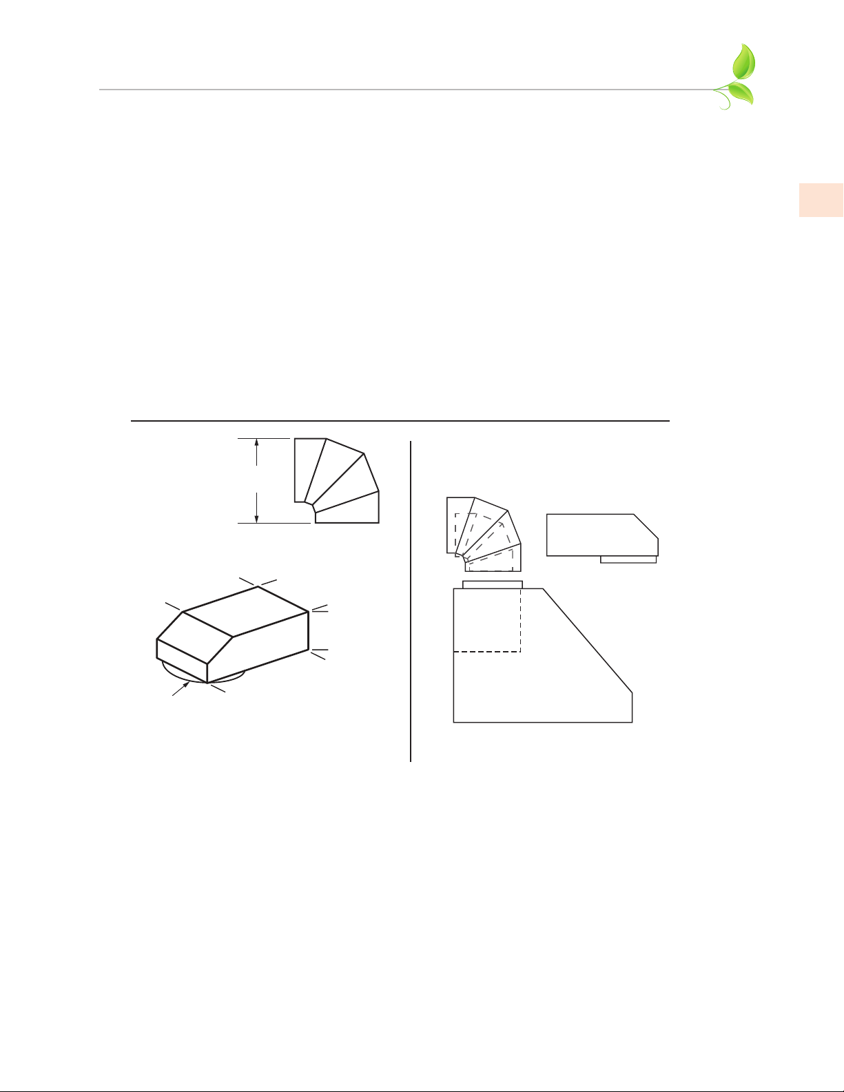
INSTALLATION
(SUITE)
VENTILATION ARRIÈREVENTILATION ARRIÈRE
Lors de la ventilation à travers le mur, un ou deux raccords coudés sont nécessaires, selon la
configuration de la soufflante:
CACHE-CONDUITS ET VENTILATION ARRIÈRECACHE-CONDUITS ET VENTILATION ARRIÈRE
Les coudes à profil bas peuvent interférer avec le cadre du cache-conduit. Montez le cache-conduit
sur la hotte et testez les coudes pour vérifier qu’ils sont bien ajustés.
COUDES POUR 900 CFM COUDES POUR 900 CFM
Les unités dotées d’un système de soufflante de 900 CFM utilisent un coude de 8 po [20,3 cm] et un
coude de 6 po [15,2 cm].
COUDES POUR 1200 CFM COUDES POUR 1200 CFM
Les unités dotées d’un système de soufflante de 1200 CFM utilisent deux coude de 8 po [20,3 cm].
Hauteurs pour le Coude et les Transitions
La unité de 600 CFM utilise un rond de 8 po [20,3 cm]
Hauteur
quand ajustée
à 90 degrés
H
La unité de 300 CFM utilise un rond de 6 po [15,2 cm]
(Dessin non à l'échelle)
FR
6 po [15,2 cm] Rond, H=8-1/2 po [21.6 cm]
8 po [20,3 cm] Rond, H=10-3/4 po [27.3 cm]
12 po
[30.5 cm]
8 po Rond
[20.3 cm]
Coude Profile Bas: 8 po [20,3 cm] en Rond à
6 x 8-1/2 po [15,2 x 21,6 cm] Rectangle
Numéro de pièce: AKVBE8
8-½ po
[21.6 cm]
6 po
[15.2 cm]
16 po
[40.6 cm]
8 po Rond
Vue de Côté
©2020 Hestan Commercial Corporation
19
Page 50
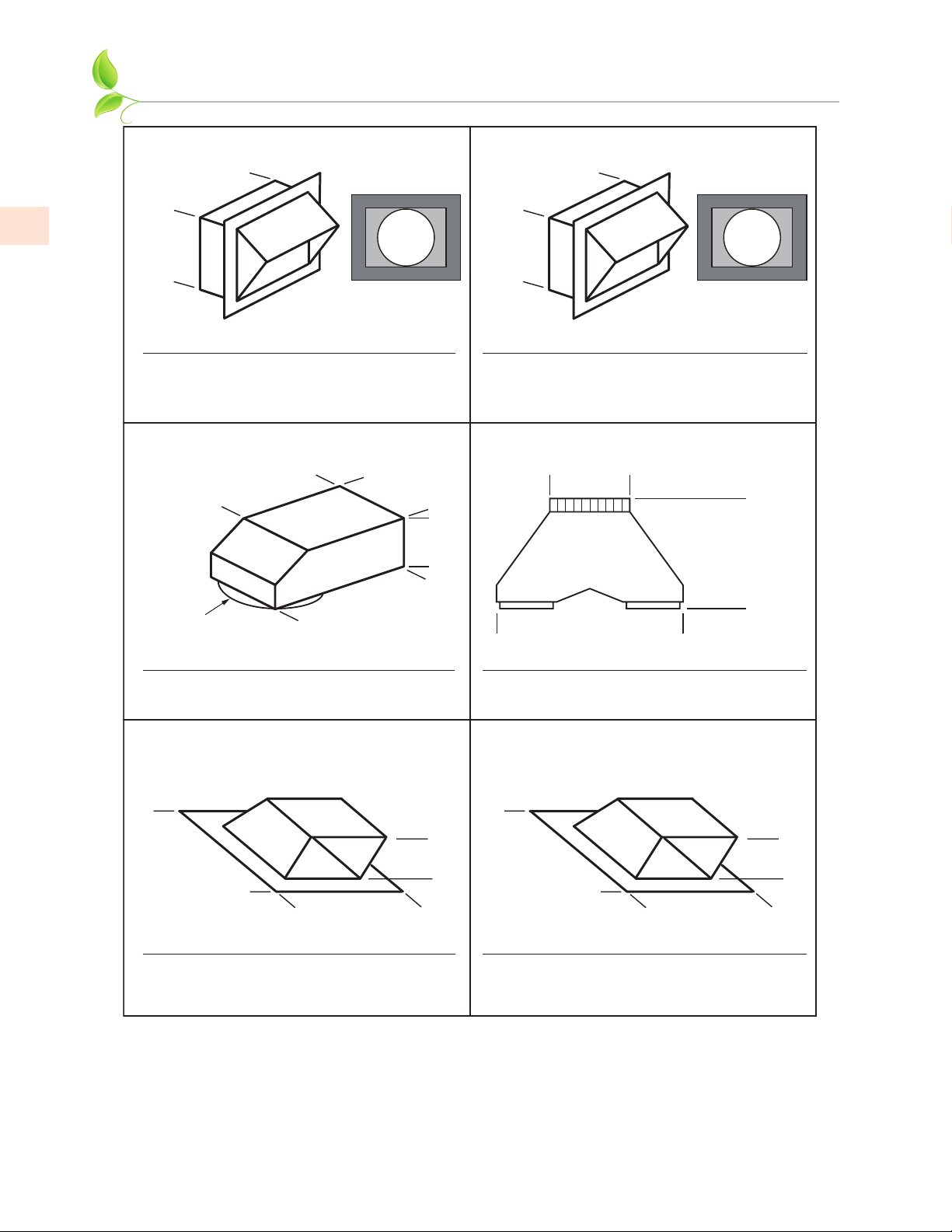
FR
ACCESSOIRES DE VENTILATION
Évent Murale Évent Murale
A, B: 8-5⁄8 po
[21,9 cm]
A: 6 po
[15,2 cm]
B: 8 po
[20,3 cm]
Vue
arrière
1-½ po bride
[3.8 cm]
A: 11 po
[27,9 cm]
B: 13 po
[33 cm]
A: 11 po [27,9 cm]
B: 13 po [33 cm]
Vue
arrière
1-½ po bride
[3.8 cm]
Article
A
B
Modèle La Description
AKVWL6 6 po Rond [15,2 cm]
AKVWL8 8 po Rond [20,3 cm]
Coude à Profil Bas
12 po
[30,5 cm]
8 po Rond
[20,3 cm]
Modèle La Description
AKVBE8
8 po [20,3 cm] en Rond à 6 x 8-1/2 po
[15,2 x 21,6 cm] Rectangulaire
Chapeau de Toit à Profil Bas
(Pas minimale 4/12)
16 po
[40,6 cm]
8-½ po
[21,6 cm]
[15,2 cm]
6 po
ModèleArticle
A
AKVWL10 10 po Rond [25,4 cm]
B
AKVWL12 12 po Rond [30,5 cm]
La Description
Transition de Soufflante Multiple
10 po [25,4 cm]
12 po [30,5 cm]
A:
17-½ po [44,4 cm]
B:
16-½ po [41,9 cm]
A:
23-¼ po [59,1 cm]
B:
30-½ po [77,5 cm]
Article
A
B
Modèle La Description
AKVT6810 6 po & 8 po à 10 po
AKVT8812 8 po & 8 po
Chapeau de Toit à Profil Bas
(Pas minimale 4/12)
à 12 po
20
16-¾ po
[42,5 cm]
Modèle La Description
AKVRC6HP 6 po Rond [15,2 cm]
AKVRC8HP 8 po Rond [20,3 cm]
©2020 Hestan Commercial Corporation
16-¾ po
[42,5 cm]
6-½ po
[16,5 cm]
22-½ po
[57,2 cm]
20-¾ po
[52,7 cm]
Modèle La Description
AKVRC10HP 10 po Rond [25,4 cm]
AKVRC12HP 12 po Rond [30,5 cm]
10-½ po
[26,7 cm]
Page 51

CACHE-CONDUIT
NO.
DESCRIPTION
MODELE
KVDC3612 CACHE-CONDUIT, VENTILATION, 36W X 12H GVP36
KVDC3612-XX CACHE-CONDUIT, VENTILATION, 36W X 12H (Couleur) GVP36
KVDC4212 CACHE-CONDUIT, VENTILATION, 42W X 12H GVP42
KVDC4212-XX CACHE-CONDUIT, VENTILATION, 42W X 12H (Couleur) GVP42
KVDC4812 CACHE-CONDUIT, VENTILATION, 48W X 12H GVP48
KVDC4812-XX CACHE-CONDUIT, VENTILATION, 48W X 12H (Couleur) GVP48
KVDC5412 CACHE-CONDUIT, VENTILATION, 54W X 12H GVP54
KVDC5412-XX CACHE-CONDUIT, VENTILATION, 54W X 12H (Couleur) GVP54
KVDC3624 CACHE-CONDUIT, VENTILATION, 36W X 24H GVP36
KVDC3624-XX CACHE-CONDUIT, VENTILATION, 36W X 24H (Couleur) GVP36
KVDC4224 CACHE-CONDUIT, VENTILATION, 42W X 24H GVP42
KVDC4224-XX CACHE-CONDUIT, VENTILATION, 42W X 24H (Couleur) GVP42
KVDC4824 CACHE-CONDUIT, VENTILATION, 48W X 24H GVP48
KVDC4824-XX CACHE-CONDUIT, VENTILATION, 48W X 24H (Couleur) GVP48
KVDC5424 CACHE-CONDUIT, VENTILATION, 54W X 24H GVP54
KVDC5424-XX CACHE-CONDUIT, VENTILATION, 54W X 24H (Couleur) GVP54
UTILISÉ AVEC
MODÈLE DU
VENTILATEUR
FR
KVDC3636 CACHE-CONDUIT, VENTILATION, 36W X 36H GVP36
KVDC3636-XX CACHE-CONDUIT, VENTILATION, 36W X 36H (Couleur) GVP36
KVDC4236 CACHE-CONDUIT, VENTILATION, 42W X 36H GVP42
KVDC4236-XX CACHE-CONDUIT, VENTILATION, 42W X 36H (Couleur) GVP42
KVDC4836 CACHE-CONDUIT, VENTILATION, 48W X 36H GVP48
KVDC4836-XX CACHE-CONDUIT, VENTILATION, 48W X 36H (Couleur) GVP48
KVDC5436 CACHE-CONDUIT, VENTILATION, 54W X 36H GVP54
KVDC5436-XX CACHE-CONDUIT, VENTILATION, 54W X 36H (Couleur) GVP54
REMARQUE: -XX indique le modèle de couleur.
CODES D’EXTENSION DE COULEUR
-BK pour Stealth - Noir -WH pour Froth - Blanc -RD pour Matador - Rouge
-YW pour Sol - Jaune -OR pour Citra - Orange -BG pour Tin Roof - Bourgogne
-PP pour Lush - Violet -BU pour Prince - Bleu -GR pour Grove - Vert
-GG pour Pacific Fog - Gris Graphite -TQ pour Bora Bora - Turquoise
-PK pour Récif - Rose -DB pour Orion - Bleu Foncé
©2020 Hestan Commercial Corporation
21
Page 52

FR
PIÈCES / SERVICE
ENREGISTREMENT DE DONNÉES DE SERVICEENREGISTREMENT DE DONNÉES DE SERVICE
La plaque signalétique contient le numéro de modèle et le numéro de série de l’appareil. Voir
«PLAQUE SIGNALÉTIQUE» à la page4 pour l’emplacement de la plaque signalétique.
C’est le bon moment pour écrire cette information dans l’espace ci-dessous. Conservez votre facture
pour la validation de la garantie.
Numéro de modèle ________________________________
Numéro de série __________________________________
Date d’installation ou d’occupation __________________
LISTE DES PIÈCES
Visiter le site Web Hestan pour consulter la liste des pièces de ce produit:
www.hestanhome.com.www.hestanhome.com.
SERVICE
Toutes les réparations dans le cadre ou en dehors de la garantie doivent être effectuées par du
personnel d’entretien qualifié. Pour localiser un réparateur agréé dans la région, s’adresser au
concessionnaire Hestan, au représentant local ou à l’usine. Avant d’appeler, veiller à avoir les
numéros de modèle et de série à portée de la main.
Hestan Commercial Corporation
3375 E. La Palma Avenue
Anaheim, CA 92806
(888) 905-7463
GARANTIE LIMITÉE
ÉLÉMENTS COUVERTS PAR LA PRÉSENTE GARANTIE LIMITÉEÉLÉMENTS COUVERTS PAR LA PRÉSENTE GARANTIE LIMITÉE
Hestan Commercial Corporation (« HCC ») garantit à l’acheteur initial d’un appareil Hestan (le «
Produit ») chez un revendeur agréé HCC que le Produit ne présente aucun vice de matière ni de
fabrication pendant une période de deux (2) ans à compter de la date de l’achat initial au détail ou
de la date de clôture en cas de construction neuve, suivant la période la plus longue (« Période de
garantie limitée »). HCC accepte de réparer ou de remplacer, à sa seule discrétion, tout composant
ou pièce du Produit dont la défaillance est due à des vices de matières ou de fabrication pendant
la Période de garantie limitée. La présente Garantie limitée n’est pas transférable et n’est offerte à
personne d’autre que l’acheteur initial au détail (« Acheteur »). La présente garantie limitée n’est
valable que pour les Produits achetés chez et reçus d’un revendeur agréé HCC dans tous les EtatsUnis, dans le District de Columbia et au Canada. La présente Garantie limitée ne s’applique qu’aux
Produits pour usage non commercial, à l’exclusion de ceux utilisés à des fins commerciales.
22
MARCHE À SUIVRE POUR UNE RÉPARATION AU TITRE DE LA GARANTIEMARCHE À SUIVRE POUR UNE RÉPARATION AU TITRE DE LA GARANTIE
En cas de défaillance du Produit pendant la Période de garantie limitée pour des raisons couvertes par
la présente Garantie limitée, l’Acheteur doit contacter immédiatement le revendeur auquel il a acheté
le Produit ou HCC au 888.905.7463.
©2020 Hestan Commercial Corporation
Page 53

GARANTIE LIMITÉE
Il incombe à l’Acheteur de rendre le Produit raisonnablement accessible pour réparation ou de régler
les frais de mise à disposition raisonnable du Produit pour réparation. La réparation sera effectuée
pendant les heures d’ouverture normales du Centre de réparation agréé par Hestan. Dans la mesure
où l’Acheteur demande une réparation en dehors des heures d’ouverture normales du Centre de
réparation agréé par Hestan, l’Acheteur règlera la différence entre le tarif normal et celui des heures
supplémentaires ou des primes. L’Acheteur doit régler tous les frais de déplacement si celui-ci
dépasse 80 km [50 miles] (dans un sens) par rapport au Centre de réparation le plus proche agréé par
Hestan.
ALLONGEMENTS AU-DELÀ DE LA PÉRIODE DE GARANTIE LIMITÉE DE DEUX ANS:ALLONGEMENTS AU-DELÀ DE LA PÉRIODE DE GARANTIE LIMITÉE DE DEUX ANS:
EN PLUS DE LA GARANTIE LIMITÉE DE DEUX ANS, LES COMPOSANTS QUI SUIVENT
BÉNÉFICIENT D’UN PROLONGEMENT DE LA GARANTIE COMME EXPRESSÉMENT ÉNONCÉ
CI-APRÈS :
1. Les brûleurs à gaz (hormis leur aspect extérieur), les éléments chauffants électriques, les moteurs
de ventilateurs (hottes de ventilation), les tableaux de commande électronique, les magnétrons
et les génératrices asynchrones (le cas échéant) du Produit sont garantis exempts de vices de
matières et de fabrication dans des conditions normales d’utilisation non commerciale et de
réparation pendant une période de cinq (5) ans au profit de l’Acheteur initial. Cela exclut la
corrosion superficielle, les rayures et la décoloration susceptibles de se produire pendant une
utilisation normale et se limite au remplacement de la ou des pièces défectueuses, tous les autres
frais, y compris ceux de main d’œuvre, de transport et de manutention, le cas échéant, étant à la
charge de l’Acheteur.
(SUITE)
FR
ÉLÉMENTS NON COUVERTS PAR LA PRÉSENTE GARANTIE LIMITÉEÉLÉMENTS NON COUVERTS PAR LA PRÉSENTE GARANTIE LIMITÉE
La présente Garantie limitée ne couvre pas ce qui suit, excluant toute responsabilité financière
de HCC : tous dommages ou vices affectant tout Produit non acheté chez un revendeur agréé
HCC; variations de coloris dans la finition ou autres dommages esthétiques ; panne ou dommages
dus à une utilisation abusive ou erronée, un accident, un incendie, une catastrophe naturelle, un
usage commercial du Produit, une interruption de l’alimentation électrique ou en gaz du Produit
; dommages résultant d’une modification, d’une installation ou utilisation incorrecte du Produit;
dommages résultant de la réparation ou du remplacement incorrect ou sans autorisation de tout
composant ou pièce du Produit; dommages résultant d’un service après vente assuré par quiconque
autre qu’un agent ou représentant agréé du réseau commercial de Hestan; usure normale et
détérioration; dommages résultant de l’exposition du Produit à une atmosphère corrosive contenant
du chlore, du fluor ou toute autre substance chimique nuisible; dommages résultant de l’absence d’un
entretien normal du Produit; dommages dont HCC n’a pas été avisé ou qui se sont produits après
expiration de la Période de garantie limitée; dommages accessoires et indirects causés par tout vice de
matière ou de fabrication.
ARBITRAGE :ARBITRAGE :
La présente Garantie limitée est régie par la Loi fédérale sur l’arbitrage. Tout litige opposant
l’Acheteur à HCC et relatif au Produit ou à la présente Garantie limitée doit être résolu par voie
d’arbitrage exécutoire exclusivement sur une base individuelle avec l’Acheteur. L’arbitrage sera
effectué par l’Association Américaine d’Arbitrage (American Arbitration Association, « AAA »)
conformément à ses règles d’arbitrage pour la protection du consommateur ou par JAMS. L’audience
d’arbitrage se tiendra devant un arbitre nommé par l’AAA ou par JAMS. L’arbitre ne devra procéder
à aucun arbitrage collectif et l’Acheteur devra renoncer à tout recours contre HCC en qualité de
représentant de tiers.
©2020 Hestan Commercial Corporation
23
Page 54

FR
GARANTIE LIMITÉE
LIMITATION DE RESPONSABILITÉ :LIMITATION DE RESPONSABILITÉ :
La présente Garantie limitée constitue l’accord définitif, intégral et exclusif entre HCC et l’Acheteur
eu égard au Produit.
IL N’EXISTE AUCUNE GARANTIE EXPRESSE AUTRE QUE CELLES ÉNUMÉRÉES ET DÉCRITES
PLUS HAUT. AUCUNE GARANTIE EXPRESSE OU IMPLICITE, Y COMPRIS SANS S’Y LIMITER,
TOUTE GARANTIE IMPLICITE DE QUALITÉ MARCHANDE OU D’ADAPTATION À UN USAGE
PARTICULIER NE S’APPLIQUERA APRÈS L’EXPIRATION DE LA PÉRIODE DE GARANTIE LIMITÉE
INDIQUÉE PLUS HAUT. AUCUNE GARANTIE EXPRESSE APPLICABLE À CE PRODUIT OFFERTE
PAR UNE PERSONNE OU ENTREPRISE QUELCONQUE N’ENGAGERA HCC. HCC NE GARANTIT
EN AUCUNE FAÇON L’ADAPTATION DU PRODUIT À UN USAGE PARTICULIER, SAUF
DISPOSITION CONTRAIRE DE LA LÉGISLATION APPLICABLE.
HCC N’ASSUME AUCUNE RESPONSABILITÉ POUR TOUT MANQUE À GAGNER, IMPOSSIBILITÉ
DE RÉALISER DES ÉCONOMIES OU AUTRES AVANTAGES NI POUR TOUT AUTRE DOMMAGE
PARTICULIER, DIRECT OU INDIRECT CAUSÉ PAR L’UTILISATION, L’USAGE ABUSIF OU
L’INCAPACITÉ D’UTILISER CE PRODUIT, QUELLE QUE SOIT LA THÉORIE JURIDIQUE SUR
LAQUELLE LA DEMANDE SE FONDE, MÊME SI HCC EST INFORMÉ DE LA POSSIBILITÉ DE TELS
DOMMAGES. AUCUN RECOUVREMENT À L’ENCONTRE DE HCC NE SERA SUPÉRIEUR AU
PRIX D’ACHAT DU PRODUIT.
SANS LIMITER LA PORTÉE DE CE QUI PRÉCÈDE, VOUS ASSUMEZ TOUS LES RISQUES ET LA
RESPONSABILITÉ DES PERTES, DOMMAGES OU BLESSURES ET DÉGÂTS MATÉRIELS SUBIS
PAR VOUS-MÊMES ET DES TIERS RÉSULTANT DE L’UTILISATION, DE L’USAGE ABUSIF OU
DE L’INCAPACITÉ D’UTILISER CE PRODUIT, QUI NE SONT PAS CAUSÉS DIRECTEMENT PAR
LA NÉGLIGENCE DE HCC. LA PRÉSENTE GARANTIE LIMITÉE FORMULE VOTRE RECOURS
EXCLUSIF.
(SUITE)
Aucune déclaration ni aucun engagement verbal ou écrit de la part de qui que ce soit, y compris sans
s’y limiter un employé, représentant ou agent de HCC, ne créera une garantie ni élargira en quoi que
ce soit la portée de la présente Garantie limitée expresse de deux (2) ans. En cas de divergence entre
la présente garantie limitée et tout autre accord ou déclaration lié ou relatif au Produit, ce sera cette
Garantie qui s’applique. Si une disposition quelconque de la présente Garantie limitée est déclarée
invalide ou inapplicable, elle sera réputée modifiée dans la limite nécessaire pour la rendre applicable
et le reste de la Garantie limitée restera valide et applicable selon ses modalités.
INTERACTION ENTRE CERTAINES LOIS ET LA PRÉSENTE GARANTIE LIMITÉE :INTERACTION ENTRE CERTAINES LOIS ET LA PRÉSENTE GARANTIE LIMITÉE :
Il se peut que certains États, Provinces et Territoires n’autorisent pas la limitation de durée d’une
garantie implicite ni l’exclusion ou la restriction des dommages directs ou indirects. Les limitations
ou exclusions qui précèdent peuvent par conséquent ne pas être applicables. Il se peut que certains
États, Provinces ou Territoires prévoient d’autres droits et recours en matière de garantie. Les
dispositions de la présente Garantie limitée n’ont pas pour but de limiter, modifier, restreindre, nier
ni exclure les conditions obligatoires de garantie prévues par des États, Provinces ou Territoires,
y compris certaines garanties implicites. La présente garantie confère des droits précis, auxquels
peuvent s’en ajouter d’autres qui varient selon le lieu.
Toute question relative à la présente Garantie limitée peut être adressée à
Hestan Commercial Corporation au (888) 905-7463
24
©2020 Hestan Commercial Corporation
Page 55

Cette page n’est pas utilisée.
Page 56

RETAIN THIS MANUAL FOR FUTURE REFERENCE
CONSERVEZ CE MANUEL POUR UNE RÉFÉRENCE FUTURE
Hestan Commercial Corporation
3375 E. La Palma Ave.
Anaheim, CA 92806
(888) 905-7463
©2020 Hestan Commercial Corporation P/N 029754 REV C
 Loading...