


HCP
ADWANCED
WEB
MANUAL
AMPLIFIER
www.hertzaudiovideo.com

HCP
Advanced Web Manual
Index |
|
|
|
1. PRECAUTIONS................................................................................................................................. |
3 |
||
2. |
INSTALLATION AND SIZES........................................................................................................... |
4 |
|
3. |
CABLE SIZE CALCULATION TABLES. 1: POWER SUPPLY / 2: SPEAKERS........................... |
4 |
|
4. |
POWER SUPPLY and REMOTE IN CONNECTION / FUSE REPLACEMENT.......................... |
5 |
|
5. |
SUBWOOFER REMOTE VOLUME CONTROL: HRC installation............................................. |
5 |
|
6. |
PRE IN / SPEAKER IN / PRE OUT................................................................................................ |
6 |
|
7. |
AUTO TURN-ON BY SPEAKER IN (without REMOTE IN) ........................................................... |
8 |
|
8. |
INSTALLATION EXAMPLES: |
|
|
|
HCP 1D: (1CH) FILTERED SUBWOOFER.......................................................................................... |
10 |
|
|
|
(1CH) FULL RANGE SINGLE CHANNEL............................................................................ |
11 |
|
HCP 2: |
(2CH) FRONT L / R............................................................................................................. |
12 |
|
|
(1CH) SUBWOOFER L+R.................................................................................................... |
13 |
|
|
(1CH) SUBWOOFER MONO INPUT.................................................................................... |
14 |
|
HCP 4: |
(4CH) FRONT + REAR........................................................................................................ |
15 |
|
|
(3CH) FRONT + SUB.......................................................................................................... |
16 |
|
|
(2CH) LEFT / RIGHT........................................................................................................... |
17 |
|
HCP 4D: (4CH) FRONT + REAR........................................................................................................ |
18 |
|
|
|
(4CH) WOOFER + MID/HI................................................................................................... |
19 |
|
|
(3CH) FRONT + SUB.......................................................................................................... |
20 |
|
|
(2CH) LEFT / RIGHT........................................................................................................... |
21 |
|
HCP 5D: (5CH) FRONT + REAR + SUB............................................................................................ |
22 |
|
|
|
(5CH) WOOFER + TW + SUB............................................................................................. |
23 |
|
|
(3CH) FRONT + SUB.......................................................................................................... |
24 |
9. |
BLOCK DIAGRAMS |
|
|
|
HCP 1D: |
........................................................................................................................................... |
25 |
|
HCP 2: |
........................................................................................................................................... |
25 |
|
HCP 4: |
........................................................................................................................................... |
26 |
|
HCP 4D: |
........................................................................................................................................... |
27 |
|
HCP 5D: |
........................................................................................................................................... |
28 |
10.TECHNICAL SPECIFICATIONS |
|
||
|
HCP 1D: |
........................................................................................................................................... |
29 |
|
HCP 2: |
........................................................................................................................................... |
29 |
|
HCP 4: |
........................................................................................................................................... |
30 |
|
HCP 4D: |
........................................................................................................................................... |
30 |
|
HCP 5D: |
........................................................................................................................................... |
31 |
Not |
|
|
|
|
Set-up |
|
|
|
|
Adjustment |
|
|
|||||||||
: AVAILABLE |
|
|
|
|
:CONTROLS |
|
|
|
|
:CONTROLS |
|
|
|
|
|
|
|
|
|||
|
|
2

HCP
Advanced Web Manual
1 PRECAUTIONS
Before installing the components, please carefully read all of the instructions contained in this manual. It is advisable to carefully follow the highlighted instructions. Failure to respect these instructions may cause unintentional harm or damage to the components.
SAFETY CONSIDERATIONS
1.Make sure your car has 12 VDC voltage negative ground electric system.
2.Check your alternator and battery condition to ensure they can handle the increased consumption.
3.Do not carry out any installation inside the engine compartment or exposed to water, excessive humidity, dust or dirt.
4.Never run cables outside the vehicle or install the amplifier next to electronic gearcases.
5.Install the amplifier in the vehicle parts where temperature is between 0°C (32°F) and 55°C (131°F). Let the amplifier outer profile be at least 5 cm (2”) far from possible walls. There must be good air circulation where the amplifier is installed. If you cover the heat sink, the amplifier goes in protection.
6.The amplifier can reach temperatures of around 80°C (176°F). Make sure it is not dangerously hot before touching it.
7.Periodically clean the amplifier without using aggressive solvents that might damage it. Don’t use compressed air, since it would push solid parts in the amplifiers. Dampen a piece of cloth with water and soap, wring it and clean the amplifier. Then use a piece of cloth dampened with water only; eventually clean the amplifier with a dry piece of cloth.
8.Make sure the location you chose for the components does not affect the correct functioning of the vehicle mechanical and electrical devices.
9.Make sure power cable is not short circuited during installation and connection with the battery.
10.Use extreme caution when cutting or drilling the car plate, checking there are no electrical wiring or structural element underneath.
11.When positioning the power supply cable, avoid to run the wire over or through sharp edges or close to moving mechanical devices. Use rubber grommets to protect the wire if it runs in a hole of the plate or proper materials if it is close to heat-generating parts.
12.Make sure all the cables are properly secured all along their length. Also, make sure their outer protective jacket is flame resistant and self extinguishing. Use a clamping screw to secure positive and negative cables just close to the amplifier respective power supply terminal blocks.
13.Choose the cable gauge according to the amplifier power and to the suggestions you can find here. Use high quality cables, connectors and accessories, as you can find in the Connection catalogue.
14.Pre-plan the configuration of your new amplifier and the best wiring routes to ease installation.
15.In order to avoid incidental damage, keep the product in the original packaging until you are ready for the final installation.
16.Always wear protective eyewear when using tools, as splints or product residue may become airborne.
TYPICAL INSTALLATION SEQUENCE
If you have any questions please refer to the Advanced Manual you can find available on www.hertzaudiovideo.com or contact your Hertz dealer or Hertz authorized service for assistance.
1.Before installing the amplifier turn off the source and all other electronic devices in the audio system to prevent any damages.
2.Using a cable with adequate AWG (see chart: Power Supply Cable), run the power wire from the battery location to the amplifier mounting location.
3.Connect the power supply with the correct polarity. connect (+) terminal to the cable coming from the battery and (-) terminal to the car chassis.
4.Put an insulated fuse holder 40 cm max far from the battery positive terminal; connect one end of the power cable to it after connecting the other end to the amplifier. Do not mount the fuse.
5.To ground the device (-) in the right way, use a screw in the vehicle chassis; scrape all paint or grease from the metal if necessary, checking with a tester that there is continuity between the battery negative terminal (-) and the fixing point. If possible, connect all components to the same ground point; this solution rejects most noise which can be generated during the audio reproduction.
6.Route all signal cables close together and away from power cables.
7.Connect the RCA input cables, the applied signal must be between 0.3 VRMS and 5 VRMS.
8.Connect the high level inputs using the proper plug. Applied signal must be between 1 VRMS and 22 VRMS. Don’t use it if you are already using Pre In preamplified connection.
9.Connect the speaker output using 10 AWG max speaker cable.
10.Don’t connect (-) L and (-) R speaker outputs together. If you use an external stereo crossover, make sure that its negative poles are not connected together.
11.The amplifier turns on by connecting the remote turn on terminal (REMOTE IN) to the source specific output. The amplifier turns on automatically, without remote signal, also if using high level inputs (Speaker IN) by setting the “AUTO TURN ON” switch to position ON.
12.The LED on the front panel lights up green indicating that the product is on. The LED lights up red if the outputs go on overload, if the thermal protection is triggered, if the speaker cables short circuit with the vehicle chassis and if the amplifier is malfunctioning.
13.The fuse/s is/are located near the power supply and speaker terminals. To replace, remove the fuse/s from the housing. Always replace the fuse of the same rating.
14.Secure all auxiliary devices you built to install the components to the vehicle structure; this insures stability and safety while driving. The amplifier detachment while driving can seriously damage the people in the vehicle and other cars.
15.When installation is over, check the system’s wiring and make sure all connections were done in the right way.
16.Put the fuse into the fuse holder. The fuse value will have to be 30% higher than the amplifier built-in one. In case the cable supplies several amplifiers, the fuse value will have to be 30% higher than the sum of the values of all other fuses in the amplifiers.
17.Listening level calibration is made by adjusting the source volume up to 3/4 of its maximum level; then, adjust the amplifier levels until you hear distortion.
SAFE SOUND
USE COMMON SENSE AND PRACTICE SAFE SOUND. PLEASE REMEMBER THAT LONG EXPOSURE TO EXCESSIVELY HIGH SOUND PRESSURE LEVELS MAY DAMAGE YOUR HEARING. SAFETY MUST BE AT THE FOREFRONT WHILE DRIVING.
Information on electrical and electronic equipment waste (for those European countries which organize the separate collection of waste)
Products which are marked with a wheeled bin with an X through it can not be disposed of together with ordinary domestic waste. These electrical and electronic products must be recycled in proper facilities, capable of managing the disposal of these products and components. In order to know where and how to deliver these products to the nearest recycling/disposal site please contact your local municipal office. Recycling and disposing of waste in a proper way contributes to the protection of the environment and to prevent harmful effects on health.
3
HCP
Advanced Web Manual
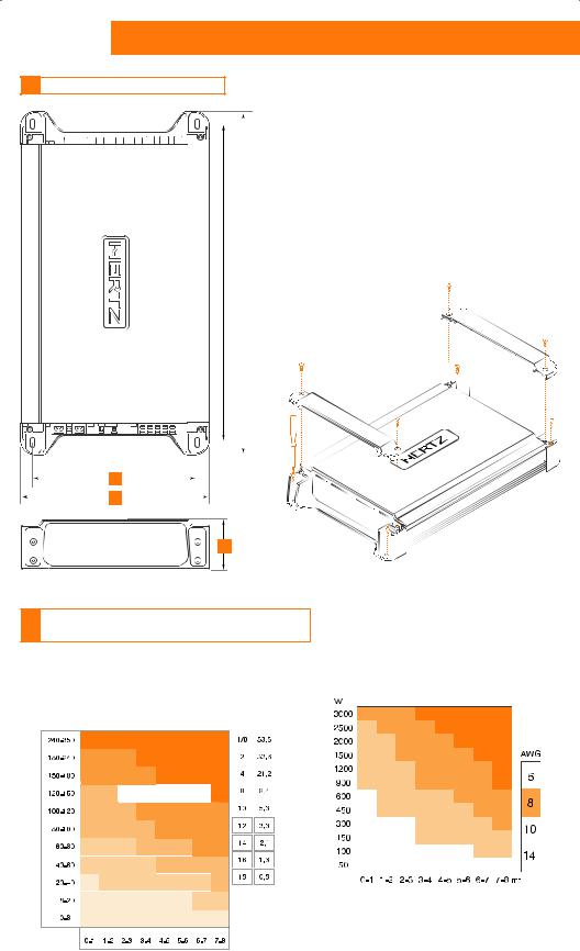
2 INSTALLATION AND SIZES
|
|
|
|
A |
B |
C |
D |
E |
|
|
|
|
|
|
|
|
|
|
|
|
|
|
HCP 1D |
215 |
200 |
190 |
166 |
50 |
mm |
|
|
|
8.46 |
7.87 |
7.48 |
6.53 |
1.97 |
in. |
|
|
|
|
|
||||||
|
|
|
|
|
|
|
|
|
|
|
|
|
HCP 2 |
215 |
200 |
190 |
166 |
50 |
mm |
|
|
|
8.46 |
7.87 |
7.48 |
6.53 |
1.97 |
in. |
|
|
|
|
|
||||||
|
|
|
|
|
|
|
|
|
|
|
|
|
HCP 4 |
315 |
291 |
190 |
166 |
50 |
mm |
|
|
|
12.40 |
11.45 |
7.48 |
6.53 |
1.97 |
in. |
|
|
|
|
|
||||||
|
|
|
|
|
|
|
|
|
|
|
|
|
HCP 4D |
215 |
200 |
190 |
166 |
50 |
mm |
|
|
|
8.46 |
7.87 |
7.48 |
6.53 |
1.97 |
in. |
|
|
|
|
|
||||||
|
|
|
|
|
|
|
|
|
|
|
|
|
HCP 5D |
345 |
321 |
190 |
166 |
50 |
mm |
|
|
|
13.58 |
12.64 |
7.48 |
6.53 |
1.97 |
in. |
|
|
|
|
|
||||||
B |
|
A |
|
|
|
|
|
|
|
D
C
E
3CABLE SIZE CALCULATION TABLES: 1: Power supply cable / 2: Speakers cable
1: Power supply cable |
|
2: Speakers cable |
|
|
|
|
|
|
|
|
|
<![if ! IE]> <![endif]>Applied power |
|
|
<![if ! IE]> <![endif]>Cable diameter |
|
|
|
|
|
|
|
|
|
|
|
||
| <![if ! IE]> <![endif]>*Current Draw I (A) |
|
|
|
|
|
|
|
|
|
|
||
|
|
|
|
|
|
|
|
|
|
|||
|
|
|
|
|
|
|
|
|
|
|||
|
|
|
|
|
|
|
|
|
|
|||
|
|
|
|
|
|
|
|
|
|
|||
|
|
|
|
|
|
|
|
|
|
|||
|
|
|
|
|
|
|
|
|
||||
|
|
|
|
|
|
|
|
|
||||
|
|
|
|
|
|
|||||||
|
|
|||||||||||
|
|
|
|
|
|
|||||||
|
|
|
|
|
|
|||||||
|
|
|
|
|
|
|
|
|
Connection length |
|||
|
|
|
|
|
|
|
|
|
|
|||
|
|
|
|
|
|
|
|
|
|
|||
|
|
|
|
|
|
|
|
|
|
|
||
|
|
|
|
|
|
|
|
|
|
|
||
|
|
Cable Length (m) |
|
|
|
|||||||
4

HCP
Advanced Web Manual
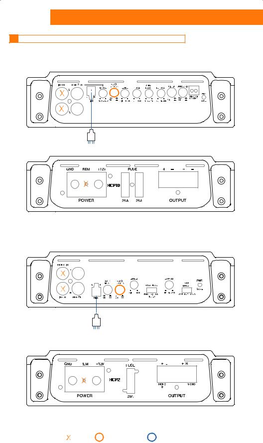
4 POWER SUPPLY and REMOTE IN CONNECTION / FUSE REPLACEMENT
GND
GND REM +12V |
FUSE |
FUSE REPLACE WARNING: |
|
|
|
||
|
|
firmly press contacts of each |
|
|
|
fuse into their fuse-holder clips |
|
POWER |
|
|
|
|
APPLY A FUSE CLOSE |
20 |
|
|
|
||
|
TO BATTERY POSITIVE POLE |
|
|
|
TO PROTECT BATTERY CABLE |
|
|
REMOTE OUT |
FUSE |
|
|
|
|
|
|
|
CAR BATTERY |
|
|
SOURCE |
|
GND |
|
AMPLIFIER FUSE
(see Tech. Spec.)
16mm/0.62 in.
POWER SUPPLY
12mm/0.47 in.
REMOTE
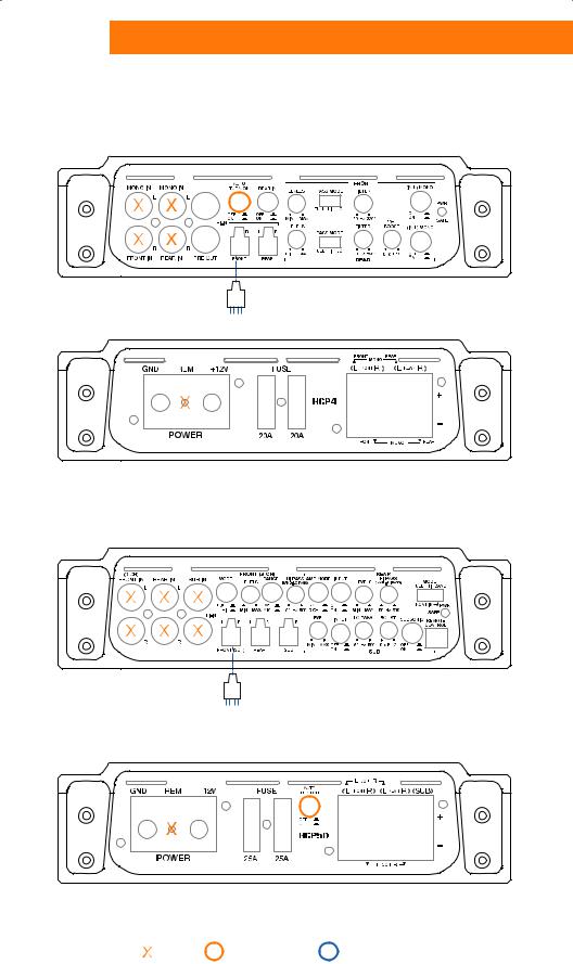
5 SUBWOOFER REMOTE VOLUME CONTROL: HRC INSTALLATION
HCP 1D
SUBWOOFER |
|
REMOTE VOLUME CONTROL |
OPTIONAL |
|
|
|
HRC |
HCP 5D
SUBWOOFER |
|
REMOTE VOLUME CONTROL |
OPTIONAL |
|
|
|
HRC |
Not |
|
|
|
|
Set-up |
|
|
|
|
Adjustment |
|
|
|
|
|||||||||
: AVAILABLE |
|
|
|
|
:CONTROLS |
|
|
|
|
:CONTROLS |
5 |
|
|
|
|
|
|
|
|
||||
|
|
HCP
Advanced Web Manual
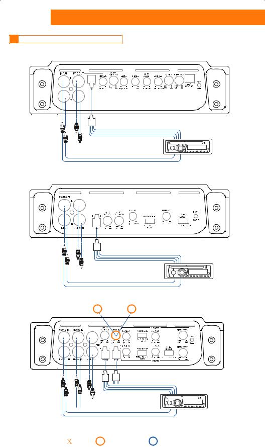
6 PRE IN / SPEAKER IN / PRE OUT
HCP 1D
|
|
R |
|
|
HI-IN |
L |
HI-LEVEL OUTPUT |
USE PRE-IN |
|
||
|
|
|
|
OR HI-IN: |
PRE OUT |
|
SOURCE |
NOT BOTH |
|
||
|
|
|
|
|
|
R |
PRE OUTPUT |
|
|
|
|
|
PRE IN |
L |
|
HCP 2
USE PRE-IN |
HI-IN |
|
|
OR HI-IN: |
PRE OUT |
NOT BOTH |
|
|
|
PRE IN |
|
|
|
If using |
If using |
HCP 4 |
FRONT INPUT OFF |
REAR INPUT ON |
|
only, select: |
select: |
||
|
|
|
|
FOR EACH INPUT |
HI-IN HI-IN |
(FRONT -REAR ) |
FRONT REAR |
USE PRE-IN |
PRE OUT |
OR HI-IN : |
(FRONT CHANNELS) |
NOT BOTH |
|
PRE IN |
PRE IN |
FRONT |
REAR |
R
HI-LEVEL OUTPUT
L
SOURCE
R |
PRE OUTPUT |
|
|
L |
|
R
HI-LEVEL OUTPUT
L
SOURCE
R
PRE OUTPUT
L
Not |
|
|
|
|
Set-up |
|
|
|
|
Adjustment |
|
|
|
|
|||||||||
: AVAILABLE |
|
|
|
|
:CONTROLS |
|
|
|
|
:CONTROLS |
6 |
|
|
|
|
|
|
|
|
||||
|
|
HCP
Advanced Web Manual
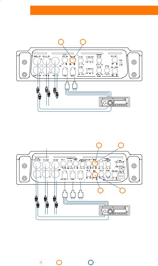
HCP 4D
If using |
OFF |
If using |
ON |
FRONT INPUT |
REAR INPUT |
||
only, select: |
|
select: |
|
|
|
R |
|
FOR EACH INPUT |
HI-IN HI-IN |
|
HI-LEVEL OUTPUT |
L |
|
||
(FRONT - REAR) |
|
||
FRONT REAR |
|
|
|
USE PRE-IN |
PRE OUT |
|
SOURCE |
OR HI-IN: |
|
|
|
(FRONT CHANNELS) |
|
|
|
NOT BOTH |
R |
|
|
|
|
||
|
|
PRE OUTPUT |
|
|
|
|
|
PRE IN |
PRE IN |
L |
|
FRONT |
REAR |
|
|
HCP 5D |
WARNING: Using 3CH mode |
REAR INPUT is not available |
FOR EACH INPUT |
|
HI-IN HI-IN |
(FRONT -REAR -SUB) |
|
|
USE PRE-IN |
|
FRONT REAR |
OR HI-IN: |
|
|
NOT BOTH |
|
|
PRE IN |
PRE IN |
PRE IN |
FRONT |
REAR |
SUB |
If using |
|
If using |
|
FRONT INPUT |
OFF |
REAR INPUT |
ON |
only, select: |
|
select: |
|
If using |
ON |
If NOT using |
OFF |
SUB INPUT, |
SUB INPUT, |
||
select: |
|
select: |
|
R
HI-LEVEL OUTPUT
HI-IN |
L |
SUB |
|
|
SOURCE |
|
R |
|
PRE OUTPUT |
|
L |
Not |
|
|
|
|
Set-up |
|
|
|
|
Adjustment |
|
|
|
|
|||||||||
: AVAILABLE |
|
|
|
|
:CONTROLS |
|
|
|
|
:CONTROLS |
7 |
|
|
|
|
|
|
|
|
||||
|
|
HCP
Advanced Web Manual
7 AUTO TURN ON BY SPEAKER IN (without REMOTE IN)
HCP 1D
ON
INPUT
L R
HCP 2
ON
INPUT
L R
|
|
|
|
|
|
|
|
|
|
|
|
|
|
|
|
|
|
|
|
|
|
|
|
|
|
|
|
|
|
|
|
|
|
|
|
|
|
|
|
Not |
|
|
|
|
Set-up |
|
|
|
|
|
|
Adjustment |
|
|
|
|
|
||
|
|
|
|
|
|
|
|
||||||||||||
: AVAILABLE |
|
|
|
|
:CONTROLS |
|
|
|
|
|
|
:CONTROLS |
|
8 |
|||||
|
|
|
|
|
|
|
|
|
|
|
|||||||||
|
|
|
|
||||||||||||||||
HCP
Advanced Web Manual
HCP 4 / HCP 4D
ON
INPUT
L R
HCP 5D
INPUT
L R
ON
Not |
|
|
|
|
Set-up |
|
|
|
|
Adjustment |
|
|
|
|
|||||||||
: AVAILABLE |
|
|
|
|
:CONTROLS |
|
|
|
|
:CONTROLS |
9 |
|
|
|
|
|
|
|
|
||||
|
|
HCP
Advanced Web Manual
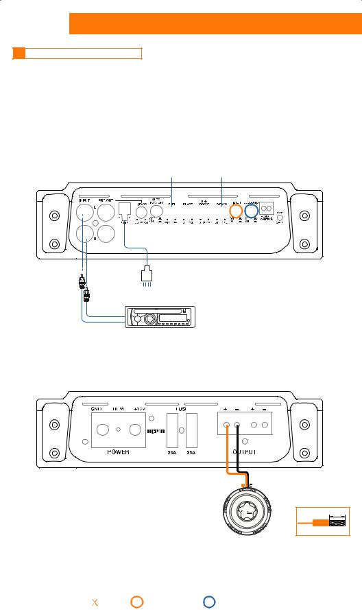
8 INSTALLATION EXAMPLES
1CH: FILTERED SUBWOOFER
INPUTS:
HCP 1D
SUB |
|
SUB |
LEVEL |
|
LO PASS |
 ON
ON
INPUT |
USE PRE-IN |
INPUT |
OR HI-IN |
||
|
L |
R |
|
R |
SOURCE |
|
|
L
OUTPUTS:
12mm/0.62 in.
SUBWOOFER
Not |
|
|
|
|
Set-up |
|
|
|
|
Adjustment |
|
|
|
|
|||||||||
: AVAILABLE |
|
|
|
|
:CONTROLS |
|
|
|
|
:CONTROLS |
10 |
|
|
|
|
|
|
|
|
||||
|
|
 Loading...