

Hercules KD-MSCAT8X8, KD-MSCAT16X16, KD-MSCAT 24X24, KD-MSCAT32X32, KD-MSCAT40X40 Operating Instructions Manual
Page 1
These Operating Instructions apply to the entire Key Digital® Hercules Series™ line of
Matrix Switchers:
KD-MSCAT8X8 ......................Matrix Switcher – (single base unit)
KD-MSCAT16X16 ................... Matrix Switcher – (2 base units of 8x8,
1 High-speed coax expansion cable, sold separately)
KD-MSCAT 24X24 ................. Matrix Switcher – (3 base units of 8x8,
3 High-speed coax expansion cables, sold separately)
KD-MSCAT32X32 .................. Matrix Switcher – (4 base units of 8x8,
6 High-speed coax expansion cables, sold separately)
KD-MSCAT40X40 .................. Matrix Switcher – (5 base units of 8x8,
10 High-speed coax expansion cables, sold separately)
Operating Instructions
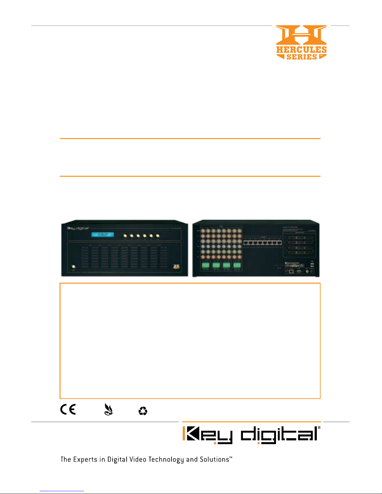
KD-MSCAT8X8
8 Inputs to 8 Outputs CAT5/6/7, RGBHV &
HDTV Matrix Switcher with Audio Control
RoHS
COMPLIANT
RoHS
COMPLIANT
WEEE
COMPLIANT
Page 2
KD-MSCAT8X8 Operating Instructions
Page 2
Read these instructions.
Keep these instructions.
Heed all warnings.
Follow all instructions.
Do not use this apparatus near water.
Clean only with dry cloth.
Do not block any ventilation openings. Install in accordance with the manufacturer’s
instructions.
Do not install near any heat sources such as radiators, heat registers, stoves, or other
apparatus (including amplifiers) that produce heat.
Do not defeat the safety purpose of the polarized or grounding-type plug. A polarized plug
has two blades with one wider than the other. A grounding type plug has two blades and
a third grounding prong. The wide blade or the third prong are provided for your safety. If
the provided plug does not fit into your outlet, consult an electrician for replacement of the
obsolete outlet.
Protect the power cord from being walked on or pinched particularly at plugs, convenience
receptacles, and the point where they exit from the apparatus.
Only use attachments/accessories specified by the manufacturer.
Unplug this apparatus during lightning storms or when unused for long periods of time.
Refer all servicing to qualified service personnel. Servicing is required when the apparatus
has been damaged in any way, such as power-supply cord or plug is damaged, liquid has
been spilled or objects have fallen into the apparatus, the apparatus has been exposed to
rain or moisture, does not operate normally, or has been dropped.
1.
2.
3.
4.
5.
6.
7.
8.
9.
10.
11.
12.
13.
Important Safety Instructions.
Please be sure to follow these instructions for safe operation of your unit
Page 3

KD-MSCAT8X8 Operating Instructions
Page 1
Table of Contents
Introduction . . . . . . . . . . . . . . . . . . . . . . . . . . . . . . . . . . . . . . . . . . . . . . . . . . . . . . . . . . . . . . . . 2
Getting Started . . . . . . . . . . . . . . . . . . . . . . . . . . . . . . . . . . . . . . . . . . . . . . . . . . . . . . . . . . . . . 5
Connecting A/V Equipment . . . . . . . . . . . . . . . . . . . . . . . . . . . . . . . . . . . . . . . . . . . . . . . . . . . . 8
Basic Operation . . . . . . . . . . . . . . . . . . . . . . . . . . . . . . . . . . . . . . . . . . . . . . . . . . . . . . . . . . . . 11
IR Remote Control . . . . . . . . . . . . . . . . . . . . . . . . . . . . . . . . . . . . . . . . . . . . . . . . . . . . . . . . . .13
Hercules Expansion . . . . . . . . . . . . . . . . . . . . . . . . . . . . . . . . . . . . . . . . . . . . . . . . . . . . . . . . .17
TCP/IP Control . . . . . . . . . . . . . . . . . . . . . . . . . . . . . . . . . . . . . . . . . . . . . . . . . . . . . . . . . . . . .17
RS-232 Control . . . . . . . . . . . . . . . . . . . . . . . . . . . . . . . . . . . . . . . . . . . . . . . . . . . . . . . . . . . . .18
Technical Specifications . . . . . . . . . . . . . . . . . . . . . . . . . . . . . . . . . . . . . . . . . . . . . . . . . . . . . . .21
Firmware Update Procedure . . . . . . . . . . . . . . . . . . . . . . . . . . . . . . . . . . . . . . . . . . . . . . . . . . 23
How to Contact Key Digital®. . . . . . . . . . . . . . . . . . . . . . . . . . . . . . . . . . . . . . . . . . . . . . . . . . . .24
Warranty . . . . . . . . . . . . . . . . . . . . . . . . . . . . . . . . . . . . . . . . . . . . . . . . . . . . . . . . . . . . . . . . . 25
© 2008 Key Digital, Inc. All rights reserved.
Always follow the instructions provided in this Operating Manual.
Page 4

KD-MSCAT8X8 Operating Instructions
Page 2
Introduction
The KD-MSCAT8X8 by Key Digital® is a part of Hercules family of switchers.
Each single unit KD-MSCAT8X8 Video/Audio Matrix Switcher is capable of switching up to 8
Component/RGBHV Video Sources/Inputs to 8 independent Zones/Outputs via CAT5/6/7 as
well as 16 input Audio sources, 8 Analog and 8 digital. Analog audio inputs have Volume, Tone,
Balance and Lip Sync Control. The switcher uses three independent 8x8 matrix switchers inside,
one for each of Video, Analog Audio and Digital Audio. Each of these signals can be independently
switched between 8 inputs and 8 outputs/zones.
Each of the Eight CAT5/6/7 Outputs can automatically format and support:
Component, RGBHV, S-Video or Composite Video, Left and Right Analog Stereo or PCM
Digital Audio and
Bi-Directional RS232 and Bi-Directional Serial IR.
Each of the Eight CAT5/6/7 Outputs offer independent matrix switching capability for Video
and Audio to run over standard unshielded CAT5/6/7 Cables for 1000 feet on Component and
700 feet on VGA signals.
* Requires 8 Additional Receiver Units KD-VACRX or wall plate Receiver KD-VACWPRX
Each of the Eight CAT5/6/7 Outputs offer independent matrix switching capability for:
Component, RGBHV, S-Video, Composite Video Inputs to run over standard unshielded
CAT5/6/7 Cable
Analog Left, Right Balanced/Unbalanced Audio Inputs to run over standard unshielded
CAT5/6/7 Cable
Independent Digital (PCM) Audio Inputs to run over standard unshielded CAT5/6/7 Cable
Each KD-MSCAT8X8 is a TCP/IP Server that can be controlled via Internet or LAN.
Can handle major standard Video and Audio formats, stereo formats, digital SPDIF and
compressed digital Audio coaxial formats. It can separate Audio and Video for independent
matrix switching.
Bandwidth of 100Mhz (1 input to 1 output) or 40Mhz(1 input to 8 outputs) supports resolutions
up to 1920 x 1080p (on RGBHV)
Each of the Eight CAT5/6/7 Outputs offer Independent Audio Control capability for:
1. Volume Control: –12 dB to +30 dB
2. Balance Control: –6 dB to +6 dB
3. Tone Control: Bass and Treble : -12 dB to +12 dB
4. Lip Sync Control: Up to 170 ms
5. Balanced and Unbalanced Audio Interconnection
Allows for multiple expansions of input Video and Audio sources to multiple displays in multiple
zones
With Key Digital’s versatility, the KD-MSCAT8X8 can also be incrementally expanded in the
field to 16x16, 24x24, 32x32, and 40x40 configuration, taking on any job from just a stress free
installation to the most complex one.
Video can be switched to black Video (mute)
›
➔
➔
➔
›
➔
➔
➔
›
›
›
›
➔
➔
➔
➔
➔
›
➔
›
Page 5
KD-MSCAT8X8 Operating Instructions
Page 3
Supported Control systems (via RS-232/IR): AMX®, Control4®, HomeLogic, LifeWare™, RTI®,
Universal® and many others
Shielded RJ45 output connectors supports 100 ohms impedance for best quality picture giving
you the flexibility to use shielded or non-shielded CAT5/6/7 cables. STP is recommended in
noise hostile environments.
KD-MSCAT8X8 makes it simple regardless of what the application requirements are.
The KD-MSCAT8X8 allows the customer to view any source on any display at any time. Key
Digital presents you with a full Video/Audio Matrix Switching solution and the capability to control
it via RS-232 or IR with your choice of any full system automation control company. It’s the
perfect solution for commercial and residential installations, putting the installer in the driver’s
seat of their boardroom or Multi Zone installation.
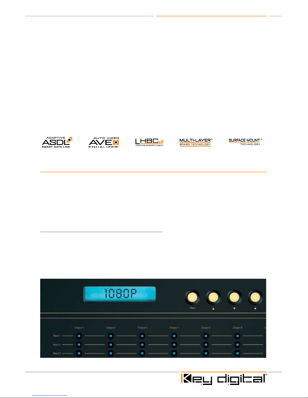
Incorporates 5 Key Digital® Exclusive Technologies
®
Exclusive Technologies
KEY FEATURES
Key Digital’s KD-MSCAT8X8, unlike other switchers in the market, has 8 CAT 5/6/7 outputs that
can be used for passing Component, RGBHV, S-Video or Composite Video signals, Analog Stereo,
Digital (PCM) Audio, Bi-directional RS232 and Bi-directional Serial IR. The switcher also offer
independent Audio Control Capability for Volume Control, Balance Control, Tone Control, Lip Sync
Control and Balance and unbalance Audio Interconnection. It supports control systems via RS-232
or serial IR such as: AMX, Control4, Life-Ware, HomeLogic, RTI, Universal and many others.
Easy to control and operate, you can switch:
Manually, using the front panel pushbuttons, LCD and LED indicators
Remotely, using the supplied IR remote control
Using the RS-232 control
Via TCP/IP, utilizing your LAN
Instant verification of your switching status, via the convenient front-panel LED’s.
›
›
›
›
›
➔
➔
➔
➔
Page 6
KD-MSCAT8X8 Operating Instructions
Page 4
Fade-to-Black and Video Mute pro-features
“Fade-to-Black” and “Video Mute” features allow you switch like a pro in a live studio.
The Fade-to-Black feature allows for switching between input/output combinations without the
usual visual signal noise that traditionally accompanies switching between Video signals. The Video
image momentarily goes to black as the KD-MSCAT8X8 Matrix Switcher selects between inputs for
the chosen output.
Video Mute enables you to mute the Video signal (the display goes to black) at the chosen output.
Massively Expandable
Massively expandable, the outputs of the 8x8 can be incremented in steps of 8, providing matrix
switching capability all the way up to 40x40.
Purchase multiple units in kits from Key Digital® to meet your expansion needs.
KD-MSCAT8X8 ......................Matrix Switcher – (single base unit)
KD-MSCAT16X16 ................... Matrix Switcher – (2 base units of 8x8,
1 High-speed coax expansion cable, sold separately)
KD-MSCAT 24X24 ................. Matrix Switcher – (3 base units of 8x8,
3 High-speed coax expansion cables, sold separately)
KD-MSCAT32X32 .................. Matrix Switcher – (4 base units of 8x8,
6 High-speed coax expansion cables, sold separately)
KD-MSCAT40X40 .................. Matrix Switcher – (5 base units of 8x8,
10 High-speed coax expansion cables, sold separately)
If you have purchased a single unit and the need for expansion aroused, all you need to do is to
order additional units plus a High-speed coax expansion cable for each additional unit.
Simply connect the units with High-speed coax expansion cables, assign appropriate number to
the unit and you done !
Technology
As for all Key Digital® products, it’s our custom technology that allows us to deliver the highest
standard of picture quality, like:
®
Exclusive Technologies
Auto Video Equalizer
™
Performs measurement of CAT5 link frequency response and performs adaptive video response
equalization for maximum video quality performance.
Adaptive Smart Data Link
™
Performs measurement of CAT5 data link quality and provides bi-directional RS232, IR,
data connectivity.
LHBC™ (Linear High Bandwidth Circuit)
To deliver the highest-quality video images, all Key Digital® products feature LHBC™, ultra-linear
components with an extremely wide bandwidth in excess of 300 MHz.
›
›
›
Page 7

KD-MSCAT8X8 Operating Instructions
Page 5
These high-bandwidth devices, along with aerospace-designed layouts, assure pristine, high
quality video image free of noise or distortions.
Our rigorous design specifications support over three-times the bandwidth commonly used for
HDTV products.
Surface Mount Technology™ and Multi-Layer Board Technology™
Circuit boards used in Key Digital® products use the very latest in materials and design, including
surface mount technology, to yield the best possible performance and reliability.
Every Key Digital® product delivers the best possible video image because our Printed Circuit
Boards (PCB’s) are designed by aerospace engineers who are extremely sophisticated at
implementing extremely wideband, low-noise circuits that communicate video signals over long
distances without degradation in signal quality.
Getting Started
The KD-MSCAT8X8 Matrix Switcher is capable of switching eight (8) sets of three-wire component
(YPbPr) Video or five-wire component (RGBHV) Video plus Analog and Digital (PCM) Audio. Since
Composite Video input would require just one BNC connector (Red, Green or Blue), up to 3
Composite inputs can be connected to each input field bringing total number of Composite inputs
on a single KD-MSCAT8X8 to 24 ! (Switching in that case would be in sets of 3) Matrix Switcher
is also capable of switching S-Video (with the appropriate cable adapter) from VCR’s, digital Video
recorders and satellite set-top receivers.
Sixteen Audio sources can be switched together or independently from Video sources.
If your source device has a VGA output connector, you will need a VGA-to-BNC breakout cable.
Note: At the time of this manual writing the KD-MSCAT8X8 Matrix Switcher does NOT perform Video processing, the
output Video format is the same as the input Video format. This means that the Video resolution is not changed
and also that if you input one form of Video, for example Component Video, the output will be in exactly the same
format. Flexible hardware and software architecture allows us, at Key Digital, update and improve our products
in accordance with market and client requirements. Always check our Web site for new product capabilities and
latest firmware updates.
Open the carton and you will find the following contents:
One KD-MSCAT8X8 Matrix Switcher unit
One +7V DC external Power Supply adapter module
IR Remote Control with batteries included
Operating Instructions Manual
Warranty Card
›
›
›
›
1.
2.
3.
4.
5.
CAUTION: When unpacking the unit, make all hookups and connections before
plugging in the Power Adapter provided with your unit. Do NOT apply power to the
unit until all Video and Audio connections have been made to your KD-MSCAT8X8
unit(s) from the “Source” devices to the Display(s) and/or Audio system(s). You
MUST use the Power Supply provided with your unit or you VOID the Key Digital
Warranty and risk damage to your unit and associated equipment.
Page 8
KD-MSCAT8X8 Operating Instructions
Page 6
Setting up your KD-MSCAT8X8 Matrix Switcher for operation:
Your KD-MSCAT8X8 Matrix Switcher is easy to configure and operate. In this section you will first
connect all of your A/V Input and Output devices to your KD-MSCAT8X8 Matrix Switcher unit.
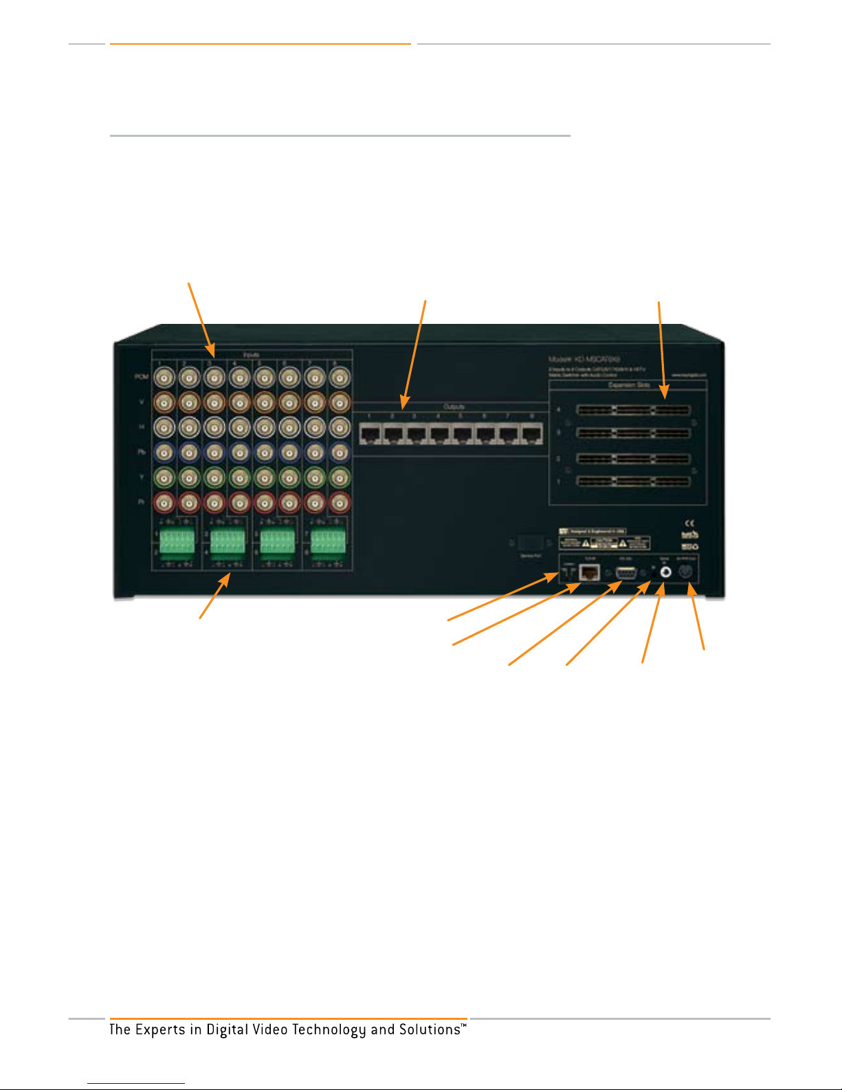
The color-coded rear-panel layout illustrates the eight Inputs and eight Outputs of the KDMSCAT8X8 Matrix Switcher, as well as the RS-232, IR and TCP/IP control interface.
Rear panel layout of the KD-MSCAT8X8 Matrix Switcher
Input BNC female
connectors
Output connectors
- female RJ-45
Expansion slots
– up to 40x40
6-pin, Phoenix type
connecting blocks
Operation Switch
TCP/IP Connection
RS-232 port
IR eye Serial IR
Power
The KD-MSCAT8X8 Matrix Switcher Video and PCM Audio Inputs are equipped with professionalgrade BNC connectors. These connectors offer a better match to Video cables than do the smaller
RCA connectors, as well as providing a positive bayonet lock when installed. Because not all
consumer equipment marketed uses BNC connector interfaces, it may be necessary to employ
RCA-to-BNC or VGA-to-BNC adapter plugs and/or cable assemblies to interface these various
devices to your high-quality Matrix Switcher.
Input Analog Audio connections are 6-pin, Phoenix type connecting blocks. Top row marked
with odd numbers, lower – with even numbers.
Output connectors are female RJ-45 for the use with CAT5/6/7, and set of KD-VACRX or KDVACWPRX baluns required for proper connection to output A/V devices.
The Video signal format must be considered when making connections to the KD-MSCAT8X8
Matrix Switcher. Simply match source A/V device’s output (be it YPbPr “Component” or RGBHV
“VGA” Video) to a similar Video signal input configuration on the KD-MSCAT8X8 Matrix Switcher.
In the event that these superior quality output formats are not available on the device in question,
›
›
›
Page 9

KD-MSCAT8X8 Operating Instructions
Page 7
then S-Video and/or Composite Video may also be interfaced with the KD-MSCAT8X8 Matrix
Switcher with the use of the appropriate adapters.
The same consideration applies to the Audio interfaces. Both Analog and Digital options are
provided on the KD-MSCAT8X8 Matrix Switcher and may be employed appropriately as Analog,
when connecting to 6-pin, Phoenix type connecting blocks and via KD-VACRX or KD-VACWPRX
baluns to the Analog Audio inputs of a Video monitor; or as Digital, when connected instead to
PCM input and via KD-VACRX or KD-VACWPRX baluns to A/V receiver having coaxial digital (PCM)
interfaces for decoding surround sound signals.
Typical Application Example for a base KD-MSCAT8X8 Matrix Switcher
Zone 1
Zone 8
Zone 2
Zone 3
Zone 4
Zone 5
KD-VACWPRX
KD-VACWPRX
KD-VACWPRX
KD-VACWPRX
KD-VACWPRX
Zone 7
Zone 6
KD-VACRX
KD-VACRX
KD-VACRX
KD-MSCAT8X8
Control System
VG
A/
RG
BH
V
IR
& RS23
2
PC
M
A
udio
VG
A/
RG
BH
V
IR
& RS23
2
PC
M
Au
dio
VG
A/
RG
BH
V
IR
&
R
S
23
2
PC
M
A
udio
VG
A/
R
GB
H
V
IR
&
R
S2
32
PC
M
A
udio
VG
A/
RG
BHV
IR
&
RS23
2
PC
M
Au
dio
VG
A/
RG
BHV
IR
&
R
S
23
2
PCM
Audio
VG
A/
RG
B
HV
I
R &
R
S2
3
2
PC
M
Au
dio
VG
A/
RG
B
HV
I
R & RS
2
3
2
PC
M
Au
dio
CA
T5/6/
7
CA
T5/6/
7
CA
T5/6/
7
Co
m
ponen
t
/VGA/R
GB
H
V
+ PC
M
+
IR
& RS
23
2
ov
er
CA
T5/6
/
7 -
1,
000’
IR
RS
23
2
TC
P
/
IP
RS232 Control
Serial IR
Optical IR
Optical IR
CA
T5/6/
7
CA
T5/6/
7
CA
T5/6
/7
CA
T5/6
/7
CA
T5/6
/7
Co
m
p
onent
/
VGA/R
GBHV
+
PC
M
+
IR
&
R
S
23
2
ov
er
C
AT
5
/
6/
7 -
1,
0
0
0’
PC/ Laptop
PC/ Laptop
PC/ Laptop
PC/ Laptop
PC PC PCPC
V
GA
/
RG
B
HV
V
GA
/
RG
B
HV
V
GA
/
RG
B
HV
V
GA
/
RG
B
HV
V
GA
/
RG
B
HV
P
CM
Au
d
io
P
CM
Au
d
io
PCM
Audio
PCM
Au
di
o
A
nalog
Audi
o
A
na
log
Au
di
o
A
na
log
Au
di
o
A
na
log
Audi
o
V
GA
/
RG
B
HV
VGA/
RG
BHV
VG
A
/
RG
BHV
Page 10

KD-MSCAT8X8 Operating Instructions
Page 8
Connecting A/V Equipment
Connecting A/V equipment to the KD-MSCAT8X8 Matrix Switcher is straightforward and
accomplished easily via the ergonomic rear panel connectors array.
Y, Pb, Pr Component Video.
Connect the three-wire (Red, Green and Blue) Y,Pb,Pr cables from your Input source of choice,
to the Red, Green and Blue color-coded BNC connectors (marked as Y, Pb, Pr on silk screen) of
any one of the eight input fields of the KD-MSCAT8X8 Matrix Switcher.
Connect Analog Audio input to any of 6-pin connecting blocks of KD-MSCAT8X8 Matrix
Switcher as following :
Active Left wire - to L- (pin1), Ground Left wire – to Pin 2,
Active Right wire - to R- (pin4), Ground Right wire – to Pin 5
If a digital Audio coaxial output is available on your Input source of choice, it can be then
connect to the Gray-coded PCM connector on the KD-MSCAT8X8 HDTV Matrix Switcher
(marked as PCM on silk screen).
Connect CAT5/6/7 cables to Outputs 1 through 8 on the KD-MSCAT8X8 Matrix Switcher.
Connect the other ends of CAT5/6/7 cables to KD-VACRX or KD-VACWPRX.
Connect corresponding Component Video jacks on your TV or monitor to KD-VACRX or KDVACWPRX via 15-pin ‘breakout’ adapter cable (VGA-to-Component).
Connect Analog Audio input of your display or A/V receiver to any of 6-pin connecting blocks of
KD-VACRX or KD-VACWPRX as following :
Active Left wire - to L- (pin1), Ground Left wire – to Pin 2,
Active Right wire - to R- (pin4), Ground Right wire – to Pin 5
If digital Audio is desired, connect your A/V receiver’s coaxial digital Audio input to RCA-style
PCM connector on KD-VACRX or KD-VACWPRX.
* For balanced Audio connection 2 Left (to pins 1 & 3) and 2 Right (to pins 4 & 6) wires has to be connected on both
KD-MSCAT8X8 Matrix Switcher and KD-VACRX or KD-VACWPRX.
RGBHV
If your Input source of choice employs RGBHV outputs, a 15-pin ‘breakout’ adapter cable will be
needed to implement the interface. In this instance:
Connect the Red, Green and Blue BNC connectors from this adapter cable to the Red, Green
and Blue connectors on any one of the eight input fields of the KD-MSCAT8X8 Matrix Switcher.
Connect the Black wire to Orange BNC connector (marked “V” – for Vertical), connect Grey
wire to White BNC connector (marked “H” – for Horizontal) in the same input field of the KDMSCAT8X8 Matrix Switcher.
Connect CAT5/6/7 cables to Outputs 1 through 8 on the KD-MSCAT8X8 Matrix Switcher.
Connect the other ends of CAT5/6/7 cables to KD-VACRX or KD-VACWPRX.
Use 15-pin ‘breakout’ adapter cable to connect your display RGBHV input to VGA/YPbPr output
of KD-VACRX or KD-VACWPRX
Connect Analog Audio input of your display or A/V receiver to any of 6-pin connecting blocks of
KD-VACRX or KD-VACWPRX as following :
›
›
➔
➔
›
›
›
›
➔
➔
›
›
›
›
›
›
Page 11

KD-MSCAT8X8 Operating Instructions
Page 9
Active Left wire - to L- (pin1), Ground Left wire – to Pin 2,
Active Right wire - to R- (pin4), Ground Right wire – to Pin 5
If digital Audio is desired, connect your A/V receiver’s coaxial digital Audio input to RCA-style
PCM connector on KD-VACRX or KD-VACWPRX.
This same connection procedure described above applies to any other peripheral device that one
may wish to interface with a desired display medium, including DVD players and game consoles.
Lower-quality S-Video (two-wire) or Composite Video (CVBS) Source Equipment:
S-Video
A “breakout” adapter cable is required to connect a satellite receiver, DVR, or S-VHS VCR to the
KD-MSCAT8X8 Matrix Switcher. This cable is equipped with an S-Video (DIN) plug at one end and
a pair of BNC plugs at the other connected to white and yellow conductors.
Connect the White (Y) conductor to the Green BNC connector in the selected input field, and
connect the Yellow (C) conductor to either the Blue or Red BNC connector in the same input
field.
Connect CAT5/6/7 cables to Outputs 1 through 8 on the KD-MSCAT8X8 Matrix Switcher.
Connect the other ends of CAT5/6/7 cables to KD-VACRX or KD-VACWPRX.
Use 15-pin ‘breakout’ adapter cable to connect KD-VACRX or KD-VACWPRX to your display by
connecting the Green BNC connector to Green input and either Blue or Red BNC connector to
the Blue or Red input on your display.
Connect Analog Audio input to any of 6-pin connecting blocks of KD-MSCAT8X8 Matrix
Switcher as following :
Active Left wire - to L- (pin1), Ground Left wire – to Pin 2,
Active Right wire - to R- (pin4), Ground Right wire – to Pin 5
Connect Analog Audio input of your display or A/V receiver to any of 6-pin connecting blocks of
KD-VACRX or KD-VACWPRX as following :
Active Left wire - to L- (pin1), Ground Left wire – to Pin 2,
Active Right wire - to R- (pin4), Ground Right wire – to Pin 5
Composite Video (CVBS) Connection
Connect the Composite Video connector (yellow) from your Input source to the Red, Green or
Blue BNC connector in the selected KD-MSCAT8X8 Matrix Switcher input field.
Since Composite Video input would require just one BNC connector (Red, Green or Blue), up to
3 Composite inputs can be connected to each input field bringing total number of Composite
inputs on a single KD-MSCAT8X8 to 24! (Switching in that case would be in sets of 3)
Use of DVP card will allow for only 1 Composite input per input field – and it has to be connected
to Green BNC.
Connect CAT5/6/7 cables to Outputs 1 through 8 on the KD-MSCAT8X8 Matrix Switcher.
Connect the other ends of CAT5/6/7 cables to KD-VACRX or KD-VACWPRX.
Use 15-pin ‘breakout’ adapter cable to connect KD-VACRX or KD-VACWPRX to your display by
connecting the Green BNC connector to Green input on your display.
➔
➔
›
›
›
›
›
➔
➔
›
➔
➔
›
›
›
›
›
›
Page 12

KD-MSCAT8X8 Operating Instructions
Page 10
Connect Analog Audio input to any of 6-pin connecting blocks of KD-MSCAT8X8 Matrix
Switcher as following :
Active Left wire - to L- (pin1), Ground Left wire – to Pin 2,
Active Right wire - to R- (pin4), Ground Right wire – to Pin 5
Connect Analog Audio input of your display or A/V receiver to any of 6-pin connecting blocks of
KD-VACRX or KD-VACWPRX as following :
Active Left wire - to L- (pin1), Ground Left wire – to Pin 2,
Active Right wire - to R- (pin4), Ground Right wire – to Pin 5
* For balanced Audio connection 2 Left (to pins 1 & 3) and 2 Right (to pins 4 & 6) wires has to be connected on both
KD-MSCAT8X8 Matrix Switcher and KD-VACRX or KD-VACWPRX.
›
➔
➔
›
➔
➔
LCD Display
Menu Button
UP Button
DOWN Button
Left Button
Right Button
Select Button
Power Button LED Indicators IR Eye
CAUTION: Now that the installation is completed, it is recommended to double
check all connections before connecting the external power supply. Once every
connection has been verified, plug the connector of the Power Supply into the power
input jack of the KD-MSCAT8X8. Always test all connections and final operation
first, before sealing cables behind walls or completing difficult wire routings. Use
a reliable “Source” to test your connections (like a DVD player) before routing or
hiding any wires behind walls or ceilings.
Page 13

KD-MSCAT8X8 Operating Instructions
Page 11
BASIC OPERATION
A “Matrix Switcher” allows you connect an output device (typically a display or A/V receiver) to input
source of your selection.
In 8x8 configuration, for instance, all 8 output devices can be connected to one input or any of 8
output devices can be connected to any of 8 inputs or any combination (group) of output devices
can be connected to any input.
All input/output combinations are configurable via the front panel pushbuttons and the selection is
clearly displayed by LCD display and LED indicators for each of the output fields. Switching can be
accomplished conveniently in any of four ways:
Manually, using the front panel pushbuttons, LCD screen and LED indicators
Remotely, using the supplied IR remote control
Using the RS-232 control
Using TCP/IP protocol over LAN.
Configuration and Setup
Manual routing of Video and Audio signals from the available inputs to selected outputs is easily
implemented on the KD-MSCAT8X8 Matrix Switcher using the front panel pushbuttons, and visually
verifiable via the LCD display and LED indicators for each combination of input/output fields.
The front panel of the KD-MSCAT8X8 Matrix Switcher provides the user with a visual representation
of cross-reference of eight Input and eight Output fields. Each of these cross-points has LED
indicator that will be lit-up when appropriate Input/Output combination chosen.
All switcher functions fully controllable via “Menu”, Directional Arrows and “Select” buttons.
Unit’s LCD display stays black until power cord plugged into outlet and “Power” button pressed.
Once “Power” button pressed LCD display will lit up and display “stand by” message.
Press any button and LCD will display the following messages : “Initialization
completed. KD-MSCAT8x8 Master”. Status “Master” means that you ether operating a single
unit or it’s a controlling (master) unit in expanded configuration. Status can be changed to “Unit #”
for expanded configuration. “Master” will always be a first unit in expanded configuration, followed
by “Unit” 2, 3, 4, 5.
At this point only “Menu” button will be unlocked, thus prompting you to enter into Configuration/
Setup menu.
The following paragraph describes Menu navigation tree. (see also the diagram below)
Pressing “Menu” button will bring “Output setup” message on LCD display.
Pressing “Up” or “Down” arrows will rotate menu through the following main menu selections :
Output Setup ➔ Input Setup ➔ Control Setup ➔ Expansion Setup ➔ Control Setup
Pressing “Menu” button again will bring “Output setup” message on LCD display.
Pressing “Left” or “Right” arrows while on any of the above menu selection will move you through
Functions selection. For instance, pressing “Left” or “Right” arrows within “Output setup” will
rotate menu through the following functions:
›
›
›
›
›
›
›
›
›
➔
›
›
Page 14

KD-MSCAT8X8 Operating Instructions
Page 12
Set Output ➔ Set to Input Video ➔ Set to Input Audio ➔ Video Mute Setup ➔ Audio Mute
Setup ➔ Mute Interval
Pressing “Select” button at this point will bring you to first function – Set Output.
Pressing “Up” or “Down” arrows while in Function menu will change the value assigned to the
Function – ether as a numerical (01, 02 e.t.c) or as a state (On, Off e.t.c)
Note: Each stand alone KD-MSCAT8X8 gives you a flexibility of selecting and switching 16 Audio
Inputs (8 Analog and 8 Digital). All 16 are fully independent and can be selected as Input to any
Output. Since the majority of installations would require switching of the same Input Video/Audio
combination most of the time, set up menu will allow you to set Video/Audio association in a such
a way that switching will be done in single command, thus reducing switching time and possible
errors. At the same time, Video and Audio switching can be done independently, providing greater
flexibility and extending range of applications in which KD-MSCAT8X8 can be used.
Menu navigation tree:
➔
›
›
Set Output
Output 01 - V01 A01
Set to Input
Video
Input 01
Set to Input
Audio
Input 01
Video Mute
Setup
ON / OFF
Audio Mute
Setup
ON / OFF
Mute
Interval
000 to 031
Output
Setup
Menu
Input Select
Input 01
Input # Audio
Volume
000 to 42
Input # Audio
Balance
000 to 12
Input # Audio
Bass
000 to 24
Input # Audio
Middle
000 to 24
Input # Audio
Treble
000 to 24
Input
Setup
LipSync
Setup
000 to 99
DC Type
Bypass
CVBS
RGBHV
YPbPr
S-Video
DC Output
Interlaced
Progressive
A/V
Association
ON / OFF
Audio
Input #
00 to 80
Expansion
Status
Master: this device
Unit #: not connected
Expansion
Setup
All Outputs
Mute
ON / OFF
IR Sensor
ON / OFF
System
Address
00 to 99
LCD
Contrast
00 to 29
TCP/IP
Address
192.168.000.000
Control
Setup
TCP/IP
Mask
225.225.000.000
Press to assign #
to the unit
KD-MSCAT8X8
SelectMenu
KD-MSCAT8X8
SelectMenu
Page 15

KD-MSCAT8X8 Operating Instructions
Page 13
IR Remote Control
Power ON Power OFF
Reserved
Up/Down
Restore
A/V Adjustments
Audio Adjustments
A/V Switching
Video Mode
Volume
Audio Balance
All Mute
Mute
Audio Mode
Tone Controls
All Restore
LipSync
Buttons functionality :
Power ON, Power OFF buttons will turn KD-MSCAT8X8 On of OFF respectively
R1
button at the time of this manual writing reserved
R2
button used for controlling All Mute, Mute, All Restore and Restore functionality. If R2 included
in command sequence for the above functions then both Video and Audio will be affected.)
R3
button used for Volume , Bass, Middle, Treble, Balance and LipSync adjustments
R4
button used for Video and Audio switching at the same time
›
›
›
›
›
Page 16

KD-MSCAT8X8 Operating Instructions
Page 14
Video Mode button used for switching Video signal without switching Audio signal
at the same time
Volume, Audio Balance, Bass, Middle, Treble and LipSync buttons used for Audio
adjustments (for Analog audio only)
All Mute button, if pressed alone, will Mute Video and Audio on all channels. If Video Mode
button pressed, followed by All Mute button press, all Video channels will be muted. If Audio
Mode button pressed, followed by All Mute button press, all Audio channels will be muted.
All Restore
(Unmute) button, if pressed alone, will Restore Video and Audio on all channels.
If Video Mode button pressed, followed by All Restore button press, all Video channels will be
restored. If Audio Mode button pressed, followed by All Restore button press, all Audio channels
will be restored.
Mute button allows to mute selected Video channel if pressed after Video Mode button pressed
or to mute selected Audio channel if pressed after Audio Mode button pressed.
Restore
(Unmute) button allows to restore selected Video channel if pressed after Video Mode
button pressed or to restore selected Audio channel if pressed after Audio Mode button pressed.
Up and Down Arrows
allow to select numeric values for Input and Output channels as well as
Audio adjustments.
Exact commands sequence for all IR remote control functions described below.
Selecting input and output combinations with the IR Remote
Configuring a stand alone or up to 5 units in expansion mode unit with the desired input and
output combination requires the following successive steps:
To switch Video and Audio – (Video/Audio association had to be setup for this mode to work),
Select Output by pressing numbers from 01 to 40 or use Up and Down arrows
Press R4
Select Input by pressing numbers from 01 to 40 or use Up and Down arrows
See as appropriate LED light will lit up
To switch Video only –
Select Output by pressing numbers from 01 to 40 or use Up and Down arrows
Press Video Mode button
Select Input by pressing numbers from 01 to 40 or use Up and Down arrows
See as appropriate LED light will lit up
To switch Audio only –
Select Output by pressing numbers from 01 to 40 or use Up and Down arrows
Press Audio Mode button
Select Input by pressing numbers from 01 to 40(for Analog), from 41 to 80(for PCM or use Up
and Down arrows
Audio/Video Association – To associate Video and Audio Inputs:
Select Video Input by pressing number 01 or use Up and Down arrows
Press R3 button
Select Audio Input by pressing number 01 or use Up and Down arrows
›
›
›
›
›
›
›
1.
2.
3.
4.
1.
2.
3.
4.
1.
2.
3.
1.
2.
3.
Page 17

KD-MSCAT8X8 Operating Instructions
Page 15
All Mute/Mute All Restore/Restore functionality.
All Mute, Mute, All Restore, Restore functions can be used separately for Video and Audio or for
Video and Audio at the same time.
All Mute button, if pressed alone, will Mute Video and Audio on all channels. If Video Mode button
pressed, followed by All Mute button press, all Video channels will be muted. If Audio Mode button
pressed, followed by All Mute button press, all Audio channels will be muted.
All Restore button, if pressed alone, will Restore Video and Audio on all channels. If Video Mode
button pressed, followed by All Restore button press, all Video channels will be restored. If Audio
Mode button pressed, followed by All Restore button press, all Audio channels will be restored.
To use Video and Audio functionality at the same time preside commands sequence with pressing
of R2.
For instance, to Mute Video and Audio on Output 1:
Select Output 1 by pressing numbers 01 or use Up and Down arrows
Press R2
Press Mute button
For Video functionality only use the following command sequence:
Select Output by pressing numbers from 01 to 40 or use Up and Down arrows
Press Video Mode button
Press Mute or Restore
For Audio functionality only use the following command sequence:
Select Input by pressing numbers from 01 to 40 or use Up and Down arrows
Press Audio Mode button
Press Mute or Restore
Audio Adjustments.
To set any Audio Input to it’s Default value (12 for Volume, 6 for Balance, 12 for Middle and
Treble)
Select Input by pressing numbers from 01 to 40 or use Up and Down arrows
Press appropriate button : Volume, Bass, Middle, Treble, Balance or LipSync
Press R3
Volume Control
Volume Control feature provided for Analog Audio (Left/Right) only. Listed below are the remote
control functions that support Audio volume control for Output 1.
To Adjust Input 1 L&R analog Audio volume:
Select Input by pressing number 01 or use Up and Down arrows
Press Volume button
Increase or decrease the volume by pressing UP or Down arrows or by pressing numbers
from 00 to 42
1.
2.
3.
1.
2.
3.
1.
2.
3.
1.
2.
3.
1.
2.
3.
Page 18

KD-MSCAT8X8 Operating Instructions
Page 16
Bass Control
Select Input by pressing numbers from 01 to 40 or use Up and Down arrows
Press Bass button
Increase or decrease the Bass by pressing UP or Down arrows or by pressing numbers
from 00 to 24
Middle Control
Select Input by pressing numbers from 01 to 40 or use Up and Down arrows
Press Middle button
Increase or decrease the Middle by pressing UP or Down arrows or by pressing numbers
from 00 to 24
Treble Control
Select Input by pressing numbers from 01 to 40 or use Up and Down arrows
Press Treble button
Increase or decrease the Treble by pressing UP or Down arrows or by pressing numbers
from 00 to 24
Balance Control
Select Input by pressing numbers from 01 to 40 or use Up and Down arrows
Press Balance button
Increase or decrease the Balance by pressing UP or Down arrows or by pressing numbers
from 00 to 24
LipSync Control
Select Input by pressing numbers from 01 to 40 or use Up and Down arrows
Press LipSync button
Increase or decrease the LipSync by pressing UP or Down arrows or by pressing numbers
from 00 to 99
IR Timing
The minimum timing interval between IR commands is 0.5 seconds.
Note: :Time interval at which screen will remain black determined by the Fade-to-Black period set
via RS-232. The minimum period here is the greater of the two: 0.5 sec or Fade-to-Black
interval. Please see Fade-to-Back Interval Set command in the RS-232 protocol section of
this manual for more information.
Serial IR with IR Extender
You may also want to use an IR extender with serial IR:
A wired IR serial connector is provided on the rear panel
1.
2.
3.
1.
2.
3.
1.
2.
3.
1.
2.
3.
1.
2.
3.
›
›
Wired IR Extender
KD-MSCAT8X8 Unit
3.5mm male-to-male mono cable
Page 19

KD-MSCAT8X8 Operating Instructions
Page 17
Hercules Expansion: Theory of Operation
At the time of this manual printing, the Hercules series KD-MSCAT8X8 Matrix Switcher is
expandable to as many as 40 configurable outputs in a block of 5 base units. This expansion
feature is factory installed and shipped to the consumer as a pre-wired and pre-tested combination
of two to five KD-MSCAT8X8 Matrix Switchers. The expansion packages are comprised of multiple
KD-MSCAT8X8 units ganged together. In the expansion configurations, the individual units are
connected by means of Expansion Slots via High-speed coax expansion cable.
Expansion can be done in the field as well by connecting additional units via High-speed coax
expansion cable and assigning proper numbers via Menu selections.
Typical Hercules KD-MSCAT8X8 Expansion Application Example
for a KD-MSCAT8X8-32X32:
Four (4) KD-MSCAT8X8 base units configured from the factory to provide
32x32 HDTV Matrix Switching
TCP/IP control
The KD-MSCAT8X8 HDTV Switcher can also be remotely controlled via TCP/IP protocol.
Static IP address and IP Mask updatable via Menu Control Setup function.
Default setting for the IP address is 192.168.000.233
Default setting for the IP Mask is 255.255.255.000
Fixed port setting is 23.
Full set of RS232 commands is available via TCP/IP protocol.
›
›
›
›
›
›
32X32 Matrix Switching
Page 20

KD-MSCAT8X8 Operating Instructions
Page 18
RS-232 Protocol and Commands
The KD-MSCAT8X8 HDTV Switcher can also be remotely controlled via its RS-232 port
by systems such as Crestron, AMX, ELAN, Control4 and others, utilizing industry standard
commands PROTOCOL:
57600 Baud rate
8 data bits
1 Stop bit
No parity
For the base KD-MSCAT8X8 HDTV Matrix RS-232 Control Switcher, you must supply
your own RS-232 cable and insert carefully in the back of the unit.
For the Hercules Expansions, your units come pre-configured from the factory with
their own RS-232 cable for you to use to connect to your PC or Control System.
RS-232 Connector type: DB-9 Female
Pin 2 = Tx, Pin 3 = Rx, Pin 5 = Gnd, Pin 4 = Pin 6, Pin 8 = Pin 7
Note: the pinout is with respect to the switcher, not the external controller.
The commands list for the KD-MSCAT8X8 HDTV Switcher is as follows:
Minimum timing interval between successive RS-232 commands is 0.2 sec.
Note: Exception is input switching commands. For input switching commands the minimum timing
interval between successive RS-232 commands is determined by the Fade-to-Black period set
via RS-232. The minimum period here is the greater of the two: 0.2 sec or Fade-to-Black interval.
Please see Fade-to-Back Interval Set for more information
1. I/O Switching Set: ‘SPOxxSIyy’
xx= output select [1 - 40]
yy = input select [1 - 40]
The expected system response format is:
<status> output xx set to input yy
Example: To select input 12 for output 23, issue the following RS-232 sequence: SPO23SI12
2. Video Mute/Unmute Set: ‘SPOxxVME’/’SPOxxVMD’
xx= output select [1 - 40]
The expected system response format is:
<status> video output xx muted (unmuted)
Example: To mute Video output 11, issue the following RS-232 sequence: SPO11VME
To unmute Video output 11, issue the following RS-232 sequence: SPO11VMD
3. Audio Mute/Unmute Set: ‘SPOyyAME’, ‘SPIyyAMD’
yy= output select [1 - 40]
The expected system response format is:
<status> audio input yy muted (unmuted)
Example: To mute Audio input 3, issue the following RS-232 sequence: SPI3AME
To unmute Audio input 3, issue the following RS-232 sequence: SPI3AMD
›
›
›
›
›
›
›
Page 21

KD-MSCAT8X8 Operating Instructions
Page 19
2. Video and Audio Mute/Unmute Set: ‘SPOxxAVME’/’SPOxxAVMD’
xx= output select [1 - 40]
The expected system response format is:
<status> video-audio output xx muted (unmuted)
Example: To mute Video and Audio output 11, issue the following RS-232 sequence: SPO11AVME
To unmute Video and Audio output 11, issue the following RS-232 sequence:
SPO11AVMD
3. Fade-to-Black Interval Set: ‘SPOxxMIyy’
xx = output select [01-40]
yy = Fade-to-Black Interval setting in the range [0~9]
The expected system response format is:
<status> output xx video fade-to-black y
Fade-to-Black interval is the time period the selected Video/Audio output is muted during the input
changing process
x 1 2 3 4 5 6 7 8 9
Fade-to-Black
interval (msec)
40 80 160 240 320 480 640 800 1200
Example:
To set Fade-to-Black interval to 5 for Output 11, issue the following RS-232 sequence: ‘SPO11MI5’
4. IR Control Set: ‘SPCIRE’, ‘SPCIRD’
The expected system response format is:
<status> IR sensor enabled (disabled)
Example: To disable the IR control ,issue the following RS-232 command: ‘SPCIRD’
To enable the IR control ,issue the following RS-232 command: ‘SPCIRE’
5. Front Panel Control Set: ‘SPCFBE’, ‘SPCFBD’
The expected system response format is:
<status> Front buttons enabled (disabled)
Example: To disable front buttons, issue the following RS-232 command: ‘SPCFBD’
To enable front buttons, issue the following RS-232 command: ‘SPCFBE’
6. Distribution Amplifier Mode Set: ‘SPOASIyy’
yy= input select [1 - 40]
The expected system response format is:
<status> all outputs to input yy
Example: To switch all Outputs to I put 4, issue the following RS-232 sequence: SPOASI4
7. Power Control Set: ‘PO’, ‘PF’
The expected system response format is:
On PO : Initialization completed Master (Unit 2,3, 4,5)
Example: To power on the unit, issue the following RS-232 sequence: PO
To power off the unit, issue the following RS-232 sequence: PF
Page 22

KD-MSCAT8X8 Operating Instructions
Page 20
8. Volume Level Set: ‘SPIxxAVzz’
xx = input select [1 - 40]
zz = volume level (see table below)
The expected system response format is:
<status> input xx volume set to zz
Example: To set the volume of input 9 to volume level -12, issue the following RS-232 sequence:
‘SPI09AV00’
Note: Audio volume control is supported in Analog mode only.
Digital Audio can be in Mute/Unmute mode only.
zz Volume (dB) zz Volume (dB) zz Volume (dB) zz Volume (dB)
00 -12 11 -1 22 +10 33 +21
01 -11 12 0 (default) 23 +11 34 +22
02 -10 13 +1 24 +12 35 +23
03 -9 14 +2 25 +13 36 +24
04 -8 15 +3 26 +14 37 +25
05 -7 16 +4 27 +15 38 +26
06 -6 17 +5 28 +16 39 +27
07 -5 18 +6 29 +17 40 +28
08 -4 19 +7 30 +18 41 +29
09 -3 20 +8 31 +19 42 +30
10 -2 21 +9 32 +20
9. Factory default: ‘SPCDF’
The expected system response format is:
<status> reset to factory default
Example: To reset the unit, issue the following RS-232 command: SPCDF
This command causes the unit to be reset to the factory default configuration:
Selected Input for every output: 1
Distribution Amplifier Mode: Enabled (Input = 1)
Unit address: 16 (stand-alone)
Fade-to-Black Interval: 6
Volume: 15
Front panel pushbuttons: Enabled
IR Control: Enabled
10. Status Query All: ‘STA’
The expected system response format is:
<status> status request
Example: To check unit status, issue the following RS-232 command: SPA
»
»
»
»
»
»
»
Page 23

KD-MSCAT8X8 Operating Instructions
Page 21
11. Status Query Control Page: ‘STPC’
The expected system response format is:
<status> status request
Example: To check unit status, issue the following RS-232 command: STPC
12. Status Query Output: ‘STPO’
The expected system response format is:
<status> status request
Example: To check unit status, issue the following RS-232 command: STPO
13. Status Query Output: ‘STPI’
The expected system response format is:
<status> status request
Example: To check unit status, issue the following RS-232 command: STPI
Technical Specifications
Note: The following Technical Specifications are for a base KD-MSCAT8X8 HDTV Matrix Switcher.
The Technical Specifications for Expansion configurations scale accordingly, with the outputs
incrementing in steps of eight (8). The expansion packages are comprised of multiple KDMSCAT8X8 units ganged together and tested from the factory with a special cable kit.
Inputs and Outputs
BNC-type color-coded input connectors, RJ-45 output connectors
Eight input arrays consisting of five RGBHV connectors, which can be used for component
YPbPr input, One Analog Audio connector and one PCM digital Audio connector.
Eight output RG-45 connectors
The Output format and resolution = the format and resolution of the selected Input source
Massively Expandable
Base KD-MSCAT8X8 unit Outputs expandable in increments of 8
Multiple units ganged together and tested from the factory provide up to 40 outputs
(requires 5 base units) for true 40x40 HDTV Matrix Switching
Video
Three BNC-type color-coded input connectors (YPbPr, RGB)
Supports S-Video and Composite Video (CVBS)
Professional Fade-to-Black and Video Mute features provided
Analog Audio
High-impedance (1K ohm) line level inputs
Analog stereo Audio volume adjustable from mute, -28 dB to +30 dB Digital Audio
Standard PCM digital format
›
›
›
›
›
›
›
›
›
›
›
›
Page 24

KD-MSCAT8X8 Operating Instructions
Page 22
Mechanical
CE, RoHS and WEEE compliant
Size: 17” x 13” x 7”
Weight: 10 lbs.
Enclosure Type: Metal
Rack Mount Size: 4 RU, brackets included
Operating Temperature Range 0° - 70° C (32° - 158° F)
Power Requirements
Each unit draws 5A @ 7V DC
External power supply provided:
Input: 110-240 VAC, 50-60 Hz
Output: + 7V DC @ 10A
For added safety and protection it is always recommended to use a good quality surge protector.
›
›
›
›
›
›
›
›
›
RoHS
COMPLIANT
RoHS
COMPLIANT
WEEE
COMPLIANT
CAUTION: No other power supply adapter can be used with the KD-MSCAT8X8 unit(s); you
must use the Power Supply provided! Using a power supply other than the one provided by Key
Digital with your unit VOIDS THE WARRANTY, may cause damage to your unit and associated
equipment, and is a potential safety hazard.
Page 25

KD-MSCAT8X8 Operating Instructions
Page 23
Firmware Update
From time to time, Key Digital may provide firmware updates for the KD-MSCAT8X8. These
updates are optional, and should only be performed as instructed by Key Digital. Below is the
procedure for updating the firmware. Please note that incorrect update processes can result in an
unusable unit. Follow the detailed directions carefully.
Firmware Update Procedure
Check our web site at www.keydigital.com for the latest firmware update ZIP file. Download
and unzip the firmware ZIP file to any directory on the PC. All of the unzipped files that are
created must be located in same directory on the PC.
Be sure power is disconnected to the KD-MSCAT8X8 unit. The power supply must be
disconnected (either from the back of the unit or from the wall outlet) to have a
complete power shutdown - reset.
With power disconnected, set the rear-panel slide switch (see page 6) to program mode
“Mode A”. Do not yet apply power to the unit.
Connect an RS-232 cable to the COM1 serial port on the PC, and the other end to the RS232 port on the rear panel of the KD-MSCAT8X8 unit. Make sure that no other devices are
using the COM1 serial port on the PC. Use of laptop computers has proven less reliable than
desktop systems. Please refrain from updating the firmware with laptops.
Apply power to the KD-MSCAT8X8 unit. The power supply must be reconnected
to the unit.
Double-click the ‘MSCAT8X8.bat’ file from within the ZIP folder. The command mode window
should pop up. Monitor this pop-up window to verify the update progress.
If an error occurs, check the RS-232 connection and repeat all of the above steps.
When the update is complete, disconnect the RS-232 cable between the unit and the PC.
Disconnect power from the KD-MSCAT8X8 unit. The power supply must be
disconnected (either from the back of the unit or from the wall outlet) to have a
complete power shutdown - reset.
With the power disconnected, set the rear-panel slide switch to “Normal” mode.
Turn on power to the
KD-MSCAT8X8 unit by reconnecting power supply.
The firmware update is now complete, and the
KD-MSCAT8X8 is ready for operation.
Upon boot-up, the LCD will display the new firmware version
1.
2.
3.
4.
5.
6.
7.
8.
9.
10.
11.
12.
Page 26

KD-MSCAT8X8 Operating Instructions
Page 24
System Design Group (SDG)
For system design questions
please contact us at:
Phone:
914-667-9700
E-mail:
sdg@keydigital.com
Key Digital Trainings
For questions about Key Digital Trainings
please contact us at:
Phone:
914-667-9700
E-mail:
training@keydigital.com
Customer Support
For customer support questions
please contact us at:
Phone:
914-667-9700
E-mail:
customersupport@keydigital.com
Technical Support
For technical questions about using Key
Digital® products, please contact us at:
Phone:
914-667-9700
E-mail:
tech@keydigital.com
›
›
›
›
›
›
›
›
Marketing and Public Relations:
For marketing and public relations information,
please contact us at:
Phone:
914-667-9700
E-mail:
marketing@keydigital.com
Shipping
For shipping questions please contact us at:
Phone:
914-667-9700
E-mail:
shipping@keydigital.com
Accounting:
For accounting questions please contact us at:
Phone:
914-667-9700
E-mail:
accounting@keydigital.com
Repairs and Warranty Service
Should your product require warranty service
or repair, please obtain a Key Digital® Return
Material Authorization (RMA) number by
contacting us at:
Phone:
914-667-9700
E-mail:
rma@keydigital.com
›
›
›
›
›
›
›
›
How to Contact Key Digital
®
Page 27

KD-MSCAT8X8 Operating Instructions
Page 25
Warranty
All Key Digital® products are built to high manufacturing standards and should provide years of
trouble-free operation. They are backed by a limited two-year parts and labor warranty.
Page 28

521 East 3rd Street, Mount Vernon, NY 10553
Phone :: 914.667.9700 Fax :: 914.668.8666
Web :: www.keydigital.com
KD-MSCAT8X8 Operating Instructions
Key Digital®, led by digital video pioneer Mike Tsinberg,
develops and manufactures high quality, cutting-edge
technology solutions for virtually all applications where
high quality video imaging is important. Key Digital®
is at the forefront of the video industry for Home
Theater Retailers, Custom Installers, System Integrators,
Broadcasters, Manufacturers and Consumers. We
provide
total video system solutions because we know
and help drive the technology, the industry, the business
and all the latest up-and-coming standards. Most of
all, we know exactly what you need for your unique
application - the right solution.
Rev 0 – June 2008
 Loading...