

Page 1

Heraeus
INDUSTRIETECHNIK
Klimaprufschrank HC 0020 - HC 0057
Climatic Test Chamber HC 0020 - HC 0057
mit TC-Steuerung
Service
Manual
D/E 12.94
Page 2

Service Manual
inhaitsverzeichnis / Table of contents
Hetaeus
INDUSTRIETECHNIK
Kaoitel / Chapter 1
Kapitel / Chapter 2 Standard Rohrschema / standard piping diagram
Kapitel / Chapter 3 Standard Schaltplane / standard circuit diagrams
Allgemeine Hinweise / general information
Fehlersuche / Beseitigung / trouble shooting
Standard SPS-Ausdruck / standard system configuration
Standard Logicad / standard logicad
Kapitel / Chapter 4 Standard Geratelisten mechanisch /
standard component lists mechanical
Standard Geratelisten elektrisch /
standard component lists electrical
Kapitel / Chapter 5
Standard Anlagen Konfiguration /
standard chamber configuration
Page 3
Heraeus
INDUSTRIETECHNIK
Allgemeine Hinweise
Fehlersuche / Beseitigung
General information
Trouble shooting
Page 4
SERVICE MANUAL
1.
Allgemeine Hinweise
HC 2020 - HC 2057
Heraeus
VOTSCH
1.1 Gerateliste
1.1.1 Kennzeichnung der
Geratelisten
1.1.2 Bauteil-Bezeichnung
1.1.3 Fabrikat-Typ
1.1.4 Material-Nr. / Bestell-Nr.
Die Gerateliste ist von links oben nach rechts unten wie foigt aufgebaut:
Unter der Spalte Kennzeichnung sind die Bauteilkurzbezeichnungen, wie
sie in den Rohrleitungs- und Schaltplanen erwahnt
Die Sortierung der Bauteilkurzbezeichnungen sind alphanumerisch (A-Z)
Z.B.A1.A2,
In dieser Spalte ist die Bezeichnung der Bauteile aufgefuhrt.
In dieser Spalte ist der Hersteller des betreffenden Bauteils erwahnt.
Sind baugleiche Produkte verschiedener Hersteller im Gerat eingebaut, so
sind diese mit # gekennzeichnet.
Die Material-Nr. andert sich dadurch nicht.
Unter dieser Nummer wird das Bauteil bei Heraeus-Votsch gefuhrt.
Bei Ersatzbedarf ist diese Material-Nr. immer mit anzugeben.
Anmerkung: Bauteile, die nur in Verbindung mit einem anderen
B1,...
Bauteil lieferbar sind besitzen dieselbe Materiai-Nr.
z.B.
Kondensatorlufter 03-M2 ist im Bauteil des
Kompressors 03-M3 enthalten.
sind,
aufgefuhrt.
1.1.5 Serien-Nr.
(sofern angegeben)
Unter dieser Spalte ist die Serien-Nr. oder der Anderungstermin einer
durchgefiihrten Anderung aufgefuhrt.
z.B.
Ab 02/91
Bis 01/91
Dieses Bauteil ist ab Auslieferung
Februar 1991 eingebaut.
Dieses Bauteil wurde bis einschlieBlich
Januar 1991 eingebaut.
evtl.
Page 5

SERVICE MANUAL
HC 2020 - HC 2057
Heraeus
VOTSCH
1.2 SchaltplSne
1.2.1 Anderung
1.2.2 Gultigkertsbereich
1.2.3 Kennzeichnung
1.2.4 Querverweise
Die Schaltplane sind geratebezogen zusammengestellt.
Die Koordinaten 1 bis 8 stellen die Strompfade dar.
In der FuSleiste sind von links nach rechts folgende Felder aufgefuhrt.
Irn Anderungsfeld wird das Anderungsdatum und der fortlaufende
Anderungsindex festgehalten, : - ungultige Schaltplane werden
im Kapitel "Anderungen" aufgefuhrt.
Im Bezeichnungsfeld sind die Geratetypen aufgefuhrt, fiir die der
betreffende Schaltpian gultig ist. Ist der Schaltplan fur alle Geratetypen
gultig,
so entfallt der Geratehinweis.
Die Ident-Nr. stellt eine Registrier-Nr. der Schaltplane dar. Bei generell
gultigen Schaltplanen wird zur Ident-Nr. noch ein Sprachkennzeichen angefugt. z.B. "d" fur deutsch; "e" fur englisch.
Der Umfang der Schaltplane ist aus der Blattnummer ersichtlich.
Innerhaib der Schaltplane sind Querverweise auf die einzeinen Schaltplanbiatter aufgefuhrt.
Diese Querverweise sind mit einem Schragstrich und der zugehorigen
Kennzeichnung fur Strompfad und Blatt versehen.
z.B.
Auf Blatt 1/8 ist ein Querverweis von PE / 3.1 angebracht.
Dies bedeutet: /3.1
Fortsetzung der Anschlusse-
auf Blatt 3
Strompfad 1
und umgekehrt ist auf Blatt 3 der Ruck-Querverweis
/1.8 aufgefuhrt.
Page 6
HC 0020 - HC 0057
SERVICE
Inbetriebnahme des Klimasystems bei Geratetypen HC 0... und HC 2...
1.
Erstbefullung und Inbetriebnahme Vor der Erstinbetriebnahme des Klimasystems muB der Wasservorratsbe-
des Klimasystems halter im hinteren Maschinenteil mit demineralisiertem Wasser voll gefiillt
MANUAL
HC2020-HC2057
werden.
des Priifraumbodens kann im hinteren, unteren Teil des Priifraumes
der Wasserzulauf und die Zirkulation des Taupunktbades beobachtet
werden.
durch den Wasserstand angehoben werden. 1st keine Befullung festzustellen,
"Pumpenstorung" in Betrieb zu setzen. Nach ca. 1 min ist der Befuliungsvorgang beendet und der Prufraumboden kann wieder eingelegt
werden.
Der Schalenwasserstand wird exakt gesteuert. Die Erstbefullung dau-
ert ca. 30 - 60 sec. Der Wassernachspeisungstakt ist 0,5 sec "EIN"
und 60 sec "AUS". die Nachspeisemenge betragt pro Takt 40 ml. Wird
nach 10 min der maximale Wasserstand in der Schale nicht erreicht,
geht die Anlage auf "Storung Wassermangel".
Bei der Umschaltung von Klima auf Temperatur (nur bei HC 2...) wird
das Wasser vom Taupunktbad uber das Ablaufmagnetventil 11-Y18
entleert. Dieses automatische Ventil bleibt 3 min geoffnet und schlieBt
dann wieder, damit bei Temperaturfahrt keine Luftzirkulation zum Prufraum entsteht.
Nun kann Klima eingeschaltet werden. Durch herausnehmen
Die Schwimmerkugel im linken, hinteren Teil des Bades mul3
so ist die Pumpe gemaB der Betriebsanleitung, Punkt 6.6
Bei Frostgefahr oder vor dem Transport sollte das gesamte Klimasystem entleert werden. Hierzu muB Klima ausgeschaltet werden und
das Handabsperrventil HV-27 neben der Pumpe geoffnet werden.
Ausgabe Marz 1992
Page 7
HC 0020 - HC
0057
SERVICE MANUAL
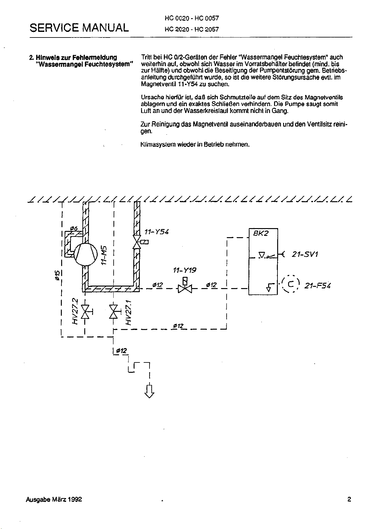
2.
Hinweis
"Wassermangel Feuchtesystem"
zur
Fehlermeldung
HC 2020 - HC
Tritt
bei HC
weiterhin auf, obwohl sich Wasser
zur Halfte) und obwohl die Beseitigung
anleitung durchgefuhrt wurde,
Magnetventil 11-Y54
Ursache hierfur ist,
ablagern und
Luft
an
Zur Reinigung das Magnetventil auseinanderbauen und den Ventilsitz
gen.
Klimasystem wieder
0/2-Gera"ten
ein
und der Wasserkreislauf kommt nicht
2057
der
Fehler "Wassermangel Feuchtesystem" auch
im
VorratsbehaMter befindet (mind,
der
Pumpentstorung gem. Betriebs-
so ist die
zu
suchen.
da0
sich Schmutzteile
exaktes SchlieBen verhindem.
in
Betrieb nehmen.
weitere Storungsursache
auf
dem Sitz des Magnetventils
in
Die
Pumpe saugt somit
Gang.
evtl.
bis
im
reini-
11-Y19
_012_
|
.
<- ;
21-5V1
21-F54
AusgabeMarz
1992
Page 8
Heraeus
VOTSCH
HC 2020 - HC 2057
SERVICE MANUAL
1.
1.1 Component list
1.1.1 Marking of component list Abbreviated component descriptions as used in piping and circuit diagrams
1.1.2 Component designation
1.1.3 Manufacturer-Type
1.1.4 Material no. / Order code
General information
The component list reads from the top left to the bottom right as follows.
are listed in the code column.
The abbreviated component descriptions are listed alphanummerically
(A-Z) e.g.A1,A2,
In this column the component designation is listed.
The manufacturer of the component concerned is listed in this column.
If identical products from various manufacturers are installed in the device,
they are marked by #.
The material no. is not affected by this.
The component is listed under this number at Heraeus-Votsch.
This material no. should always be stated when ordering spare parts.
Note:
Components which can only be delivered in
B1,...
conjunction are listed under the same material no.
1.1.5 Serial no.
(if applicable)
E.g. Condenser fan 03-M2 is incorporated in
compressor 03-M3
The serial number or date of modification of any changes which have been
affected are listed in this column.
Eg.
As of 02/91
Until 01/91
This component is installed as of February 1991.
This component was installed up to and including
January 1991.
Page 9
Heraeus
VOTSCH
HC 2020 - HC 2057
SERVICE
MANUAL
1.2 Circuit diagrams
1.2.1 Revision
1.2.2 Validity
1.2.3 Marking
1.2.4 Cross references
The circuit diagrams have been compiled on a device-specific basis.
Coordinates 1 to 8 represent current paths.
Various fields at the bottom of the circuit diagrams give the following information from left to right.
The revision field lists the date of revision and the serial revision index.
Circuit diagrams thus becoming outdated are listed in the chapter
"modifications".
The various device types to which the circuit diagram is applicable are
listed in the description
types,
the chamber designation is omitted.
The ID no. represents a circuit diagram registration number. Circuit dia-
grams which are applicable to all devices are also provided with a language
specification in addition to the ID no.
E.g. "d" for German; "e" for English
Page numbers define the extent of the circuit diagrams.
The circuit diagrams include cross references to the individual circuit dia-
gram sheets.
These cross references are marked by a slash and the applicable current
path and sheet number designation.
E.g. sheet 1/9 includes a cross reference PE / 3.1.
This means: /3.1
field.
If the circuit diagram is applicable to all device
Connections continuedon sheet 3
current path 1
Sheet 3, on the other hand, includes the appropriate return cross
reference/1.8
Page 10

HC 0020 - HC 0057
SERVICE MANUAL
Initial Operation of Humidification System of Chambers HC 0 ...and HC 2...
HC 2020 - HC 2057
1.Initial
filling-up and operation
of the humidification system
Prior to operating the humidification system, the water supply tank in the
rear of the machine section must be topped-up with demineralized water.
Then the humidification system can be started. If you remove the test space floor plate, you can see the water inlet in the lower rear part of the test
space and the circulation of the dew point
left part of the bath should be lifted by the water level. If the filling-up fails,
activate the pump according to operating instructions (item 6.6 "pump
faults"). The filling process takes approx. 1 minute. Replace floor of test
chamber.
The level in the water bath is accurately controlled. The initial filling process lasts about 30 - 60 sees. The water feeding cycle for "ON" is .5 sec.,
for "OFF" 60 sees. The feeding quantity per cycle is 40 ml. If maximum
bath level is not reached after 10 minutes, a fault signal indicating "lack of
water" will be emitted.
In case of changeover from "humidity" to "temperature" (this applies only
to HC 2...) the water from the dew point bath is drained via solenoid discharge valve 11-Y18. This automatic valve stays open for 3 minutes, then
it closes again to prevent the circulation of air during the thermal testing
process.
To render it frost-resistant and prior to transport, the entire humidification
system should be drained. For this purpose, switch off the humidification
system and open the manual check valve HV-27 next to the pump.
bath.
The float ball in the rear
Ausgabe Juni 1993
Page 11

HC 0020 - HC
HC 2020 - HC
0057
2057
SERVICE MANUAL
2.
Suggestion regarding
fault signal "lack of water
humidification system"
(Concerning HG 0/2 only). Should this signal continue although
the supply tank holds sufficient water (at least half full) and the pump
trouble has been corrected ace. to operating instructions, the solenoid
valve 11-Y54 might be responsible for the malfunction; the reason
being that dirt particles on the valve seat impede proper closing of the valve.
Consequently, the pump takes in air and the water circulation can't be
started.
To remove dirt, dismantle solenoid valve and clean the valve seat.
Then start humidification system again.
J r
)
21-F54
Page 12
Heraeus
INDUSTRIETECHNIK
Rohrschema
Aufstellungsplan
Piping diagram
Layout diagram
Page 13

06 (11-F2
20/25bgp/
PW\
Disee Z«fc*Y*xig iet
Bgontm - Jode VovU-
Vcrwert^g Oder
Psraonon W sffaftxr
«td
oartaKlcf.
varfoigt
trtoularen Wattmob BOB)
Heraeus
INCHJSTRIETECHNIK
72336 Balingen
R404A - 0.7kg
Druckangaben
in bar Oberdruck
pressure indication
in baro
Rohrscherna
Piping diagramm
Plan de tuyautage
HC 0020/0033/0057
Zusatzeinrichtung
Qpfj
i accessories
ona
Accessoires
z. Nr.: RPL21065
Page 14
Heraeus
INDUSTRIETECHNIK
Schaltplane
SPS-Ausdruck
Logicad (Querverweisliste)
EA-Listing
Circuit diagrams
System configuration
Logicad
I/O listing
Page 15
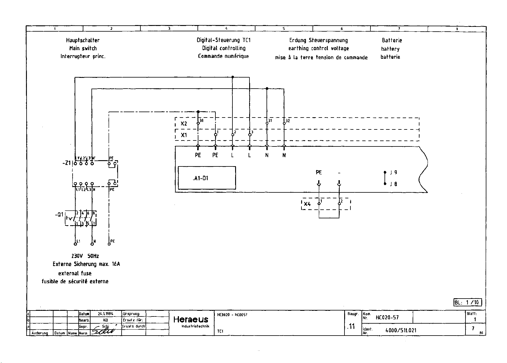
Hauptschatfer
Main switch
Interrupteur princ.
Digital-Steuerung
TC1
Digital controlling
Commande numeYique
Erdung Steuerspannung Batterie
earthing control voltage battery
mise
5 la
terre tension
de
commande batterie
-\
Externe Sicherung
external fuse
fusible
de
Anderung Datum
230V 50Hz
max. 16A
s&curife' externe
Name
Datum
Bearb.
Gepr.
Norm
24.1.1994
Kii
Ursprung:
Ersatz
fur:
Ersatz durch
Heraeus
Indus trietechnik
HC0020 - HC0057
TC1
Baugr.
.11
Kofli.
Nr. HC020-57
Ident.
Nr.
4000/511.021
[BL:
1 /10
Blaft:
1
Page 16
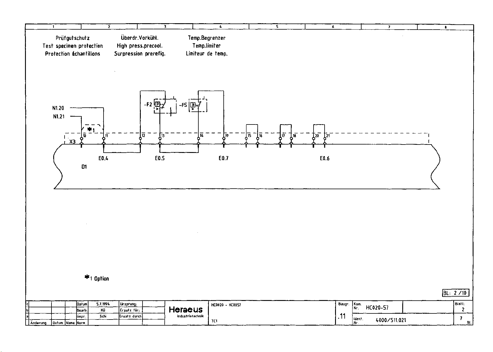
Priifgutschutz Uberdr.Vorkiihl.
Test specimen protection High press.precool.
Protection ichantillons Surpression prerefig.
Temp.Begrenzer
Temp.limiter
Limiteur de temp.
Anderung Datum
Name
Datum
Bearb.
Gepr.
Norm
'1 Option
5.7.1994
Ku
Schi
Ursprung:
Ersatz fur:
Ersatz durch
Heraeus
Industrietechnik
E0.7
HC0020 - HC0057
TC1
T—T
T—r~
E0.6
Baugr.
.11
HC020-57
Went. 4000/511.021
|BL:
2 /10 I
Blatt:
2
Page 17
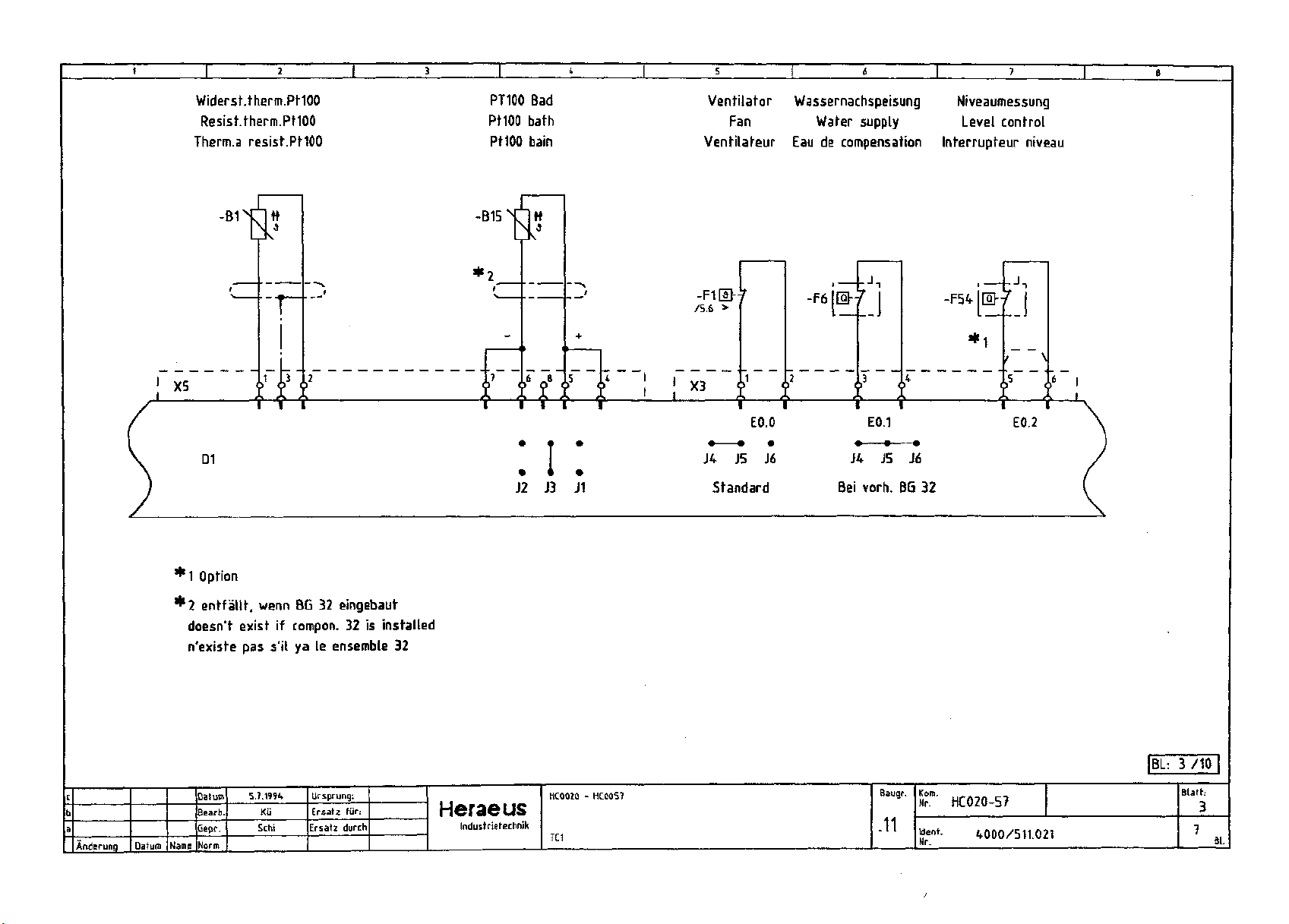
Widerst.therm.PHOO
Resist.therm.PtlOO
Therm.a resist.PtlOO
X5
D1
1X1
1 i
PT100 Bad
Pt100 bath
Pt100 bain
-B15
11
it it f
I III
' I '
• • •
J2
J3 J1
Ventilator Wassernachspeisung Niveaumessung
Fan Water supply Level control
Ventilateur Eau de compensation Interrupteur niveau
I 1
/5.6
X3
J4
LJL
EO.O
J5 J6
Standard
-F6
LJL
I I
E0.1
• • •
J4 J5 J6
Bei
vorh.
BG 32
-F5t
, \
I I
E0.2
Anderung
*1 Opti
Datum Name
ion
2 entfallt, wenn BG 32 eingebaut
doesn't exist if compon. 32 is installed
n'existe
pas s'il ya le ensemble 32
Datum
Bearb
Gepr.
Norm
5.7.1994
Ku
Schi
Ursprung:
Ersatz
Ersatz durch
fiir:
Heraeus
Industrietechnik
HC0020 - HC0057
TC1
Baugr.
.11
' HC020-57
Ident.
Nr.
4000/511.021
|BL:
3
Blath
3
Page 18
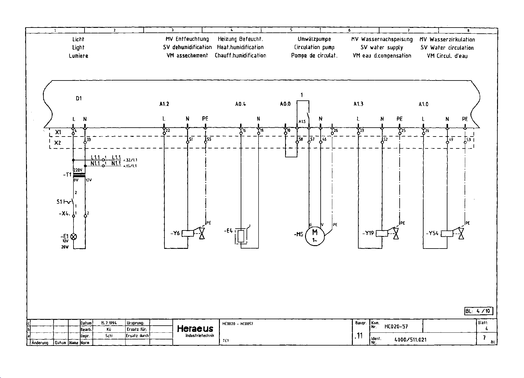
Lichf
Light
Lumiere
MV Ent-feuchtung Heizung
Befeuchf.
SV dehumidificafion Heat.humidification
VM assechement Chauff.humidification
Umwalzpumpe
Circulation pump
Pompe de circulat.
MV Wassernachspeisung MV Wasserzirkulafion
SV water supply SV Water circulation
VM eau d.compensation VM Circul.
d'eau
-T1
S1hv\
-X4.
-E1®
12V
20W
L N
220V
y
I
D1
*- '•' O- =-!=-!. - 32/11
N"O1 NI.I s;
12V
15/1;1
A1.2
L
-Y6
A0.4 AO.O
PE
N
A1.5
JU
51
PE
SB
-M5,
N
-X-
PE
M
A1.3
L
&
-Y19
A1.0
PE
N
52
PE
L
PE
-Y54
1-
Anderung
Name
Datum
Bearb.
Qepr.
Norm
15.7.1994
Kii
Schi
Ursprung:
Ersatz fur:
Ersatz durch
Heraeus
Industrietechnik
HC0020 - HC0057
TC1
Baugr.
.11
Kom.
Nr.
HC020-57
Ident.
Nr.
4000/511.021
|BL:
4 /10 I
Blath
4
Page 19
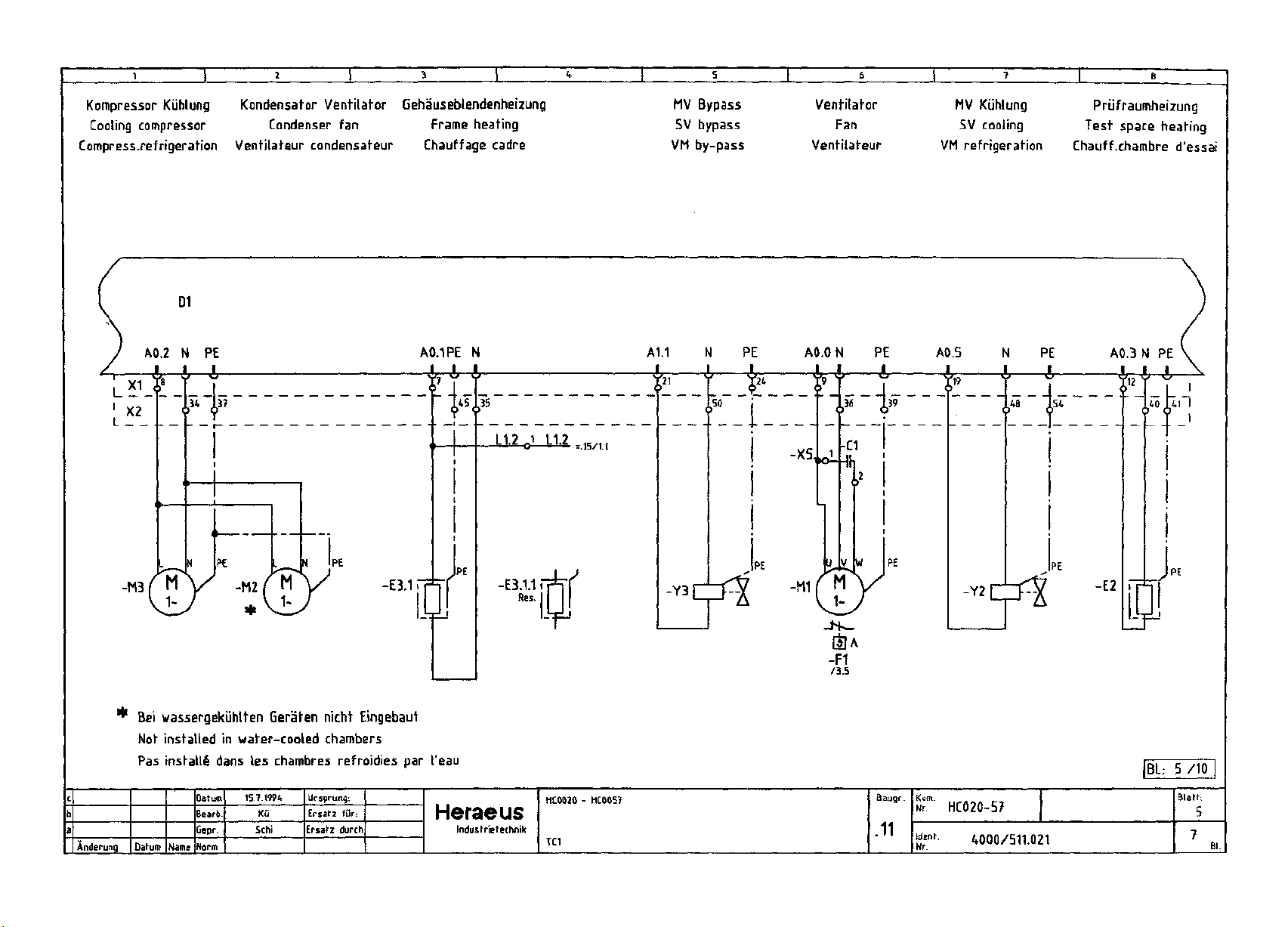
Kompressor Kiihlung
Cooling compressor
Compress.refrigeration
D1
Kondensator Ventilator Gehauseblendenheizung
Condenser fan Frame heating
Ventilateur condensateur Chauffage cadre
MV Bypass
SV bypass
VM by-pass
Ventilator
Fan
Venfitafeur
MV Kuhlung
SV cooling
VM refrigeration
Priifraumheizung
Test space heating
Chauff.chambre
d'essai
A0.2 N PE
34 137
PE
-M3f M
* Bei wassergekiihtten Geraten nicht Eingebaut
Not installed in water-cooled chambers
Pas install! dans les chambres refroidies par 1'eau
-M2
-E3.1
A0.1PE N
-Hi
iO
L1-2
,15/1.1
A1.1 N PE AO.O N PE A0.5 N PE
-J, 4, X
fr
48 154
f-l
PE
-Y3
-Y2
PE
|BL:
PE
5 /10
Anderung Datum
Name
Datum
Bearb
Cepr.
Norm
15.7.1994
Kti
Schi
Ursprung:
Ersatz fur
Ersatz durch
Korn.
:
Heraeus
Industrietechnik
HC0020 - HC0057
TC1
Baugr.
.11
Ident.
Nr.
HC020-57
4000/511.021
Blatt:
5
Page 20

O
LH
O
C3
01
O
XI
.leg
XI O <u
UJ
"g
LJ
"3
™
I
C
£
_
°"
°
j& ~°
'-°
.9!
"c
«
T3 ° OJ
«s"
3
c
ra
B
c
o
*
4)1
21
V Y
cu
-H5
E
a
Page 21
5
7
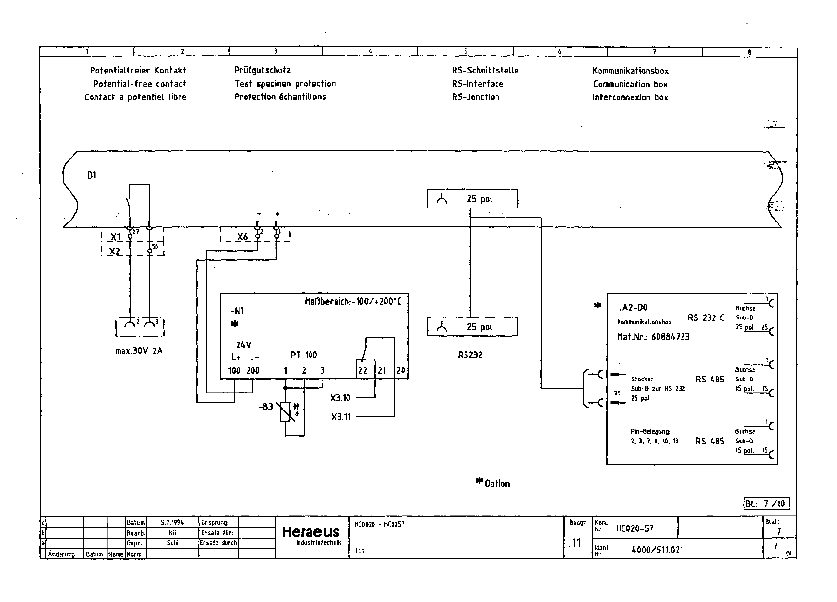
Potentialfreier Kontakt
Potential-free contact
Contact a potentiel libre
Prufgutschutz
Test specimen protection
Protection
I _
X6j2_L'
-N1
*
24V
L+ L-
100 200
e'chantillons
I I
PT 100
1 2 3
Mef3bereich:-1OO/+2OO°C
21
X3.10
X3.11
20
RS-Schnittstelle
RS-lnterface
RS-Jonction
A 25 pol
A 25 pol
RS232
Kommunikationsbox
Communication
Interconnexion
It
.A2-D0
Kommunikationsbox
-c
—c
Mat.Nr.:
"™
Sfecker
1
Sub-D
25 pol.
Pin-Betegung:
2,
3. }, 9. 10. 13
60884723
zur RS 232
box
box
RS 232 C
RS
485
RS
485
BuchsE
Sub-D
25 pol.
Suchse
Sub-0
15 pol.
BuchsE
Sub-D
15 pol.
v
25/-
u.
15
U.
r
Anderung Datum
Name
Datum
Bearb,
Gepr.
Norm
5.7.1994
Ku
Schi
Ur sprung:
Ersatz
fur:
Ersatz durch
Heraeus
Industrietechnik
HC0020 - HC0057
TC1
*Opti
on
Baugr.
.11
HC020-57
4000/511.021
|BL:
7 /10 I
Blath
7
Page 22
=.11/5.4
L1.2
-T1
220VII24V
ovllov
180VA
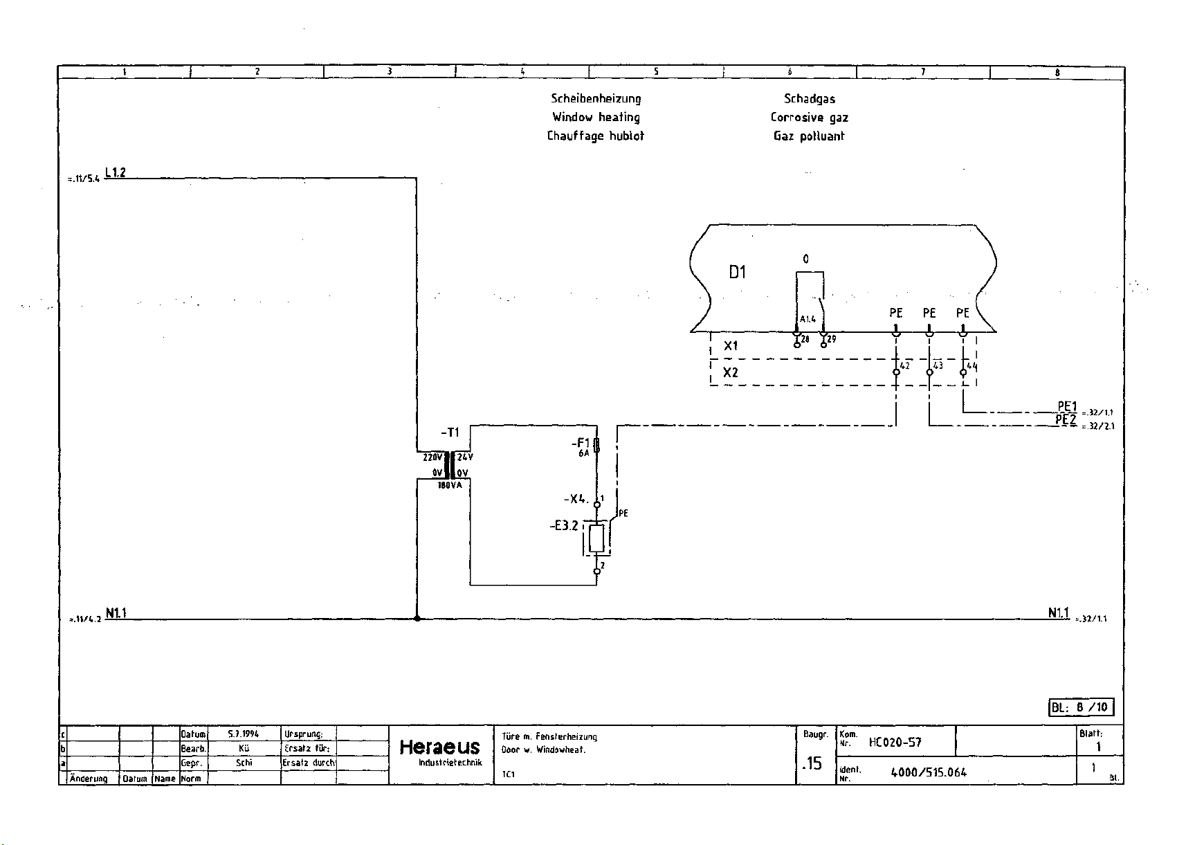
Scheibenheizung
Window heating
Chauffage hublofr
-XV
11
X1
X2
D1
Schadgas
Corrosive
gaz
Gaz polluant
A1.4
I
PE
PE PE
I I 1_
--
=32/2.1
=.11/4.2
Anderung
N1.1
Datum
Name
Datum
Bearb.
Cepr.
Norm
5J.1994
Ku
Schi
Ursprung:
Ersatz
fur:
Ersatz durch
Heraeus
Indusfrietechnik
Ture
Door
TC1
m.
w.
-E3.2
Fensterheizung
Windowheat.
Baugr.
.15
Ident.
Nr.
HC020-57
V000/515.064
N1.1
|BL:
=.32/1.1
8 /10
Blath
1
Page 23
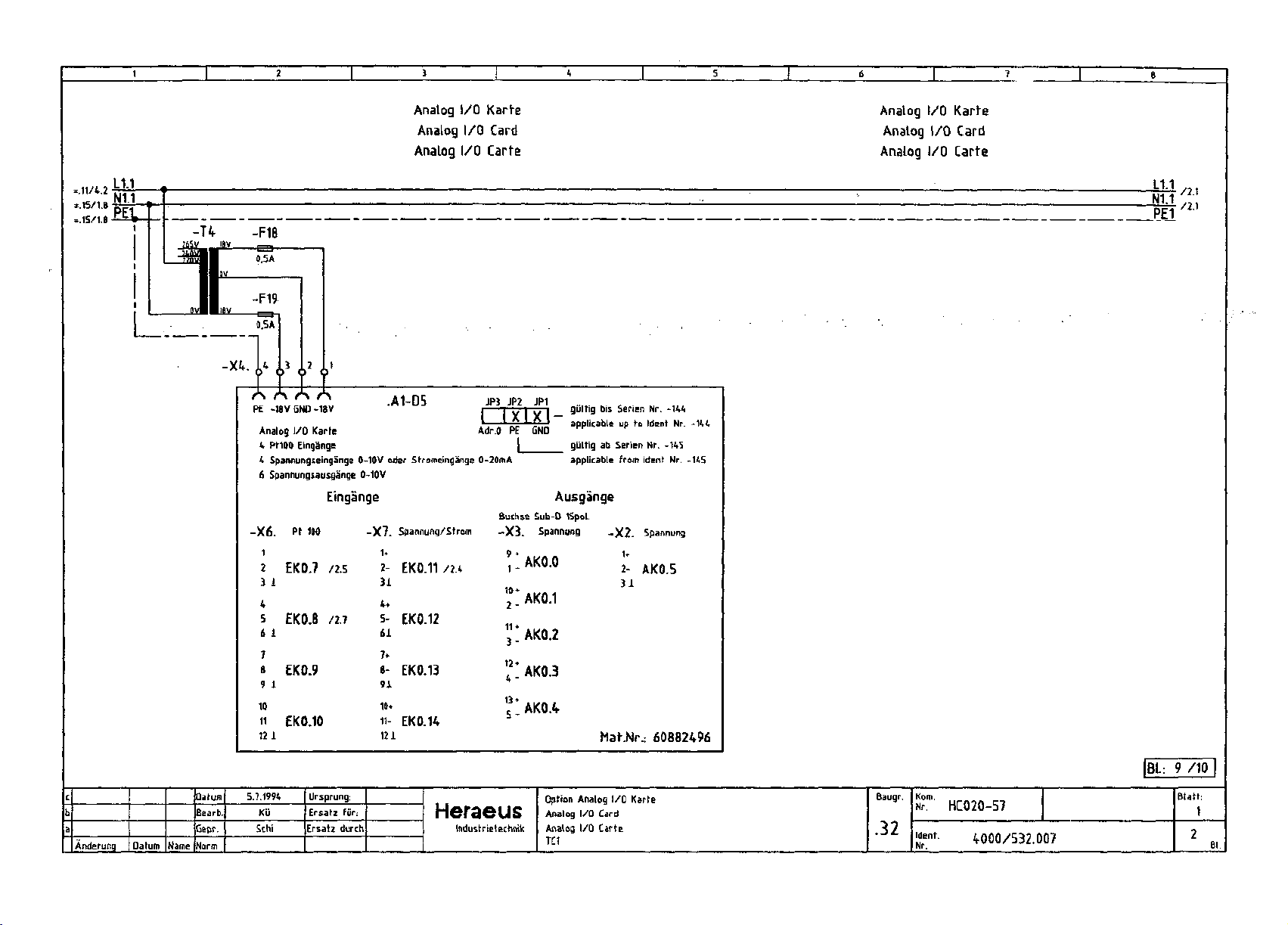
Analog I/O Karts
Analog I/O Card
Analog I/O Carte
Analog I/O Karte
Analog I/O Card
Analog I/O Carte
=.11/4.2
=.15/1.8
=.15/1.8
PE -1BVGND-18V
Analog
I/O Karte
4
PtWO Eingange
4
Spannungseingange 0-10V oder Stromeingange 0-20mA
6
Spannungsausga'nge 0-10V
.A1-D5
Eingange
X6.
1
2
3 1
4
5
6 1
7
8
9 I
10
11
121
Pt 100
EK0.7 /2.5
EK0.8 /2.7
EK0.9
EK0.10
-X7.
u
2-
31
4*
561
7*
891
10*
11121
Spannung/Strom
EK0.11 /2.4
EK0.12
EK0.13
EK0.14
JP3
JP2 JP1
i 1
T7—I
Adr.O PE GND "
j giiltig ab Serien Nr. -145
giilHg
r^ I yun ty
ippUHhle "P
applicable from Ident Nr. -145
Ausgange
Buchse Sub-D 15pol.
Span
-X3
9 *
AKO.O
1 -
10*
AK0.1
2 -
11 •
AK0.2
3 -
12*
AK0.3
4 -
13*
AK0.4
r
3
bis Serien Nr. -144
vitA
.jet ICM in . -IHH
*" "*"* *" "
-X2.
Spannung
2-
AK0.5
31
Mat.Nr.:
60882496
144
L1.1
N1.1
PE1
/2.1
/2.1
Anderu
|BL 9 /IP
Datum
Bearb.
Qepr,
Datum
ing
Name
Norm
5.7.1994
KG
Sthi
Ursprung:
Ersatz fiir
Ersatz durch
Baugr.
.32
Kom
Nr. HC020-57
Ident.
Nr.
4000/532.007
Option Analog I/O Karte
:
Heraeus
IndustrietEChnik
Analog I/O Card
Analog I/O Carte
TC1
Blath
1
Page 24

/1.8
/1.8
=.15/1.8
Feuchteregelung mit Vaisala
Humidity controlling w. Vaisala
Unabhangige Feuchtemessung
Independent humidity measuring
PT100 Bad
PtiOO bath
Pt1OO bain
PtiOO bew. Temp.
PtiOO movable Temp.
PtiOO mobile Temp.
Zuf. B2
Zuf. B1.1
Anderuni
is.
7.12.94
5.7.94
datum
Ku
Kii
Name
Datum
Bearfa
Bepr.
Norm
7.12.1994
Kii
Schi
Ursprung:
Ersatz fur:
Ersatz dutch
Heraeus
industrierethnik
Option Feuchtefuhler
Humidify sensor
Humidife capteur
TCI Vaisata
Stecker 5
Baugr.
.32
Kom.
Ident.
Nr.
HC020-57
4000/532.007
BL:
10/10
Blatt:
2
Page 25

Bearbelter
Prufer
:
Jltzer Projekt-Datet : HC0_TC.GPS
:
5Tfl-fl4 Letzte onderung : 85-12-94
11:39
1. SymbolerkIaerung
2.
SymbolerkXaerung
3. ElnschaXtbed.
4.
Elnnschaitbed.
5. Stoerungen
6.
Stoerg./Temp.
7.
Ventilator
8. Kueh\g. 1-st. <!_>
9.
Kueh\g. 1-st.
18.
Helzung
11.
Schwe\\uerte
12.
Beg\elth.u.Opt
13.
Pruefgutschutz
14.
Feuchte
15.
Feuchte
16.
Feuchte
17.
Feuchte
18.
Feuchte
19.
Feuchte
20.
Sch&dg&s
CRD-Zelchnung, kelne nnderung
finderung
1-st.
CD
Datum Name
21.
4*
Kunden
ProJ.Nr
BUtt
Ers.
f.
Ers.
d.
BIatt-ZeichnungsNr
B\att-Benennun9
I/O
HC0.TC
ft/21
Datum
Bearb
Gepr
Date
I
85-12-94
Bltzer
STfl-R4
HC0_TC
11:39
IHERflEUS-1ndus trletech.
1
Ba'i.
Projektname:
Lnoen
HC0020/57
Page 26

Symbolerklaerung
!
SymbolXaenge
max.
16
Zelchen
:
=
xxE:...
xxfl:...
xxM:...
M:SflSTOER Merker
M:HUPE Merker
M:SERVICE Merker
xx = 00...99
... =
•
CflD-Zelchnur»9f kelne
onderun9
Datum
Elngaenge
Flusgaenge
Def.
Same I stoerme \ dung
Baugruppe
StromIaufpIans
bXleblge Zelchen-
foXge , Blank
nlcht zuXaesslg
finder
Merker
Hupe/Summer
Service
ung
des
Proj.Nr
BUtt
Ers.
Ers.
B\att-ZeichnungsNr
Name
B\att-Benennung
M 0.0
M 0.1
M 0.2
f.
d.
zbF:...
vbF:...
vbS:...
zbS:...
vbOxx:...
zbCzzz:>... Zaehtmerk.
d.Scha\tzyc.-K*nal
zbCzzz:<...
d.Scha\tzyc.-Kana\
vbCzzz:>... Zaehlwert
> Limit
d.Scha\tzyc.-K*na\
HC0_TC
1^21
Fehterneldg.
an
C-FV-ogrAfwiteH
Fehlerrueckmg.
vom
C-ProgranmtelX
Zusitzfunktlon
vom C-Pr©9r*nmtel\
Qutttterung
Zusatzfkt.
an C-Pr.
Optlonsmerker
zzz
Ruecksetz.
zzz
zzz
Datum
Bearb
Gepr
Date
05-12-94
Bltzer
STfl-fl4
I
HC0_TC
—Symbo\erkIaerung
ZZZ = 001...
064
Fort\aufende
Nummer
SchaltzyoKanaXs
1
11:39
= >
des
Limit
IHERRE
Proj
HC
JS-Industrletech.
E.H.1
Ingen
ektname:
9820^57
Page 27

SyciboXerkXaerung
SymboXXaenge
max.
16
=
Zelchen
:
vbRyyy:OM...
Eln
vort
vbRyyy:>...
stelgend
.....
CRD-Zelchnung,
Anderung Datum Name
vbRyyy:ST>...
SteII9roessenansteuerg.
Frelazbe stelgend
vbRyyy:Ll...
Limit 1 Intern
vbRyyy:L3...
Limit 3 Intern
vbRyyy:l_5...
LinIt 5 Kundenaenderbar
vbRyyylTl...
ToleranzbAnd
vbRyyylPS...
Pruef9utschutz
kelne nnderung
RegXer
C-ProgrammtelX
RegXer
z.B.
Helzen
RegXer
RegXer
RegXer
RegXer
RegXer
1
RegXer
yyy
yyy
yyy
yyy
yyy
yyy
yyy
yyy
Proj.Hr
BXatt
Ers.
f.
Ers.
d.
B
X att-ZeichnungsNr
B
X att-Benennung
zbRyyy:ON... Qulttler9.
RegXer
vbRyyy:<...
slnkend
vbRyyy:ST<...
SteX
Frelgabe slnkend
vbRyyy:L2...
Limit 2 Intern
vbRyyy:L4...
Llcilt 4 Kundenaenderb*r
vbRyyy:L6...
Limit 6 Kundenaenderbar
vbRyyy:T2...
ToXeranzband
HC8_TC
yyy Eln an C-Pr.
RegXer
z.B.
KuehXen
RegXer
Xgroessenansteuerg.
RegXer
RegXer
RegXer
RegXer
2
Datum
2/21
Bearb
Gepr
Date
SyroboX
I
yyy
yyy
yyy
yyy
yyy
yyy
05-12-94
Bltzer
STfl-fW
HC0_TC
erk
yyy =
FortXaufende
KanaXnummer
des
RegXers
1 =
Ist>Llmlt
0 =
Ist<Llmlt
1 = ausserh.
ToXeranz
11:39
X aerung
000...
007
IHERflEUS-Industrletech.
[
BaXLnqen
Proj«
jktname:
3020/57
Page 28

vbS:On
M:SERVICE
:
zbS:On
l
-E3
vbO00:Drucker
vbO01:ZET
vbO02:Tlefentfeu
vbO03:Druck\uft
vbO04:CO2_Kueh\
vbO05:Schadgas
vbO06:Beregnung
vbO07:Bestrah\
vbO08:kapFeu.Zu
vbO09:kapFeu.fes
CflD-Zelchnung,
nnderung
Intern,
veruendet !
kelne nnderung
Datum
nlcht
Nane
Proj.Nr
BUtt
Ers.
f.
Ers.
d.
B\att-Ze
B1att-Benennung
HC0_TC
3/-21
LchnungsNr
Datum
Bearb
Gepr
Date
•sjigtsaaMWIIcgMlHERflELIS-1 ndustr
STH-FI4
I
HC0.TC
Elnschaltbed.
Projektname:
letech.
1
Page 29

vbR002'ONBad
vbR006:ONDlff
vbR009:OWent
vbR013:ONFeuTaup
vbR014:ONFeuKap.
vbR816:0NHelzSch
vbR020:ONTecip2
vbR022:ONTenp4
vbR025:ONFeucht2
vbR036:ONPtl00
vbR031:ONPU00
vbR032:ONPtl00
vbR033:ONPtl00
vbR050:ONPFITro
vbR052:ONPFINass
vbR053:
ONPriif
1
2
3
4
rau
Intern,
nlcht
veruendet!
•
•
]
i
i
1
i
i
i
:
CflD-Zelchnung,
snderung
kelne nnderung
D&tun
Proj.Nr
B\*tt
Ers. f.
Ers. d.
B\att-ZeichnungsNr
B X Att-Benennung
HC0.TC
4/-21
Datum
Bearb
Gepr
Date
05-12-94
Bltzer
STfl-fl4
I
HC0_TC
EInnscha\tbed.
11:39
IHERHEUS-Industrletech.
I
B-=I.'I.
ProjeUtnane:
Lngen
HC0820/57
Page 30

zbS:On
CflD-Zelchnung,
Mnderung Datum
kelne finderung Proj.Nr HC0_TC
BUU 5/21
Ers.
f.
Ers.
d.
Hacie
B\aii-Ze
B X aii-Benennung Sioerungen
LchnungsNr
Datum
Bearb
Gepr STR-FI4
DateI HC8_TC
05-12-94
Bltzer
11:39
HERREUS-1ndustrleiech.
ProjektnaMe:
HC0020/57
Page 31

CflD-Zelchnur>9i kelne nnderung Proj.Nr HC9_TC
BUtt
Ers.
f.
Ers.
d.
BIAii-Ze LchnungsHr
Mnderung
D&tuci
Nane
BIait-Benennung
Datum
Bearb
Gepr STR-R4
Date
I
65-12-94
Bltzer
HCB_TC
11:39
HERREUS-IndustrletecP
HC9020/-57
Page 32

zbS:On
Q2E:Thernok.Went
i
I-T—i
n
zbF:
Thernok.
n
P"ent
CAD-Zelchnung, kelne onderung
nnderung Daturo Nane
ProJ.Hr
BUtt
Ers.
f.
Ers.
d.
B\att-ZeichnungsNr
BIatt-Benennung
HC0.TC
7/-21
Daiun
Bearb
Gepr
Date
I
02
Ventilator
05-12-94
Bltzer
STfl-fl4
HC0.TC
11:39
HERliEUS-1
Ba\Ingen
ProJ«
fktname:
HC<
3829^57
ndustr L-etech.
Page 33

zbS:On
zbFlUeberdr^Kl
03tt:Kuehlun9
CflD-Zelchnung, kelne nnderung Proj.Nr HC8_TC
mderung Datum Mane
BUtt
Ers.
f.
Ers.
d.
B\att-Ze
BI aii-Benennung
8/-21
LchnungsNr
Datun 05-12-94
Bearb BLtzer
Gepr
STfl-fl4
Daiet HCB_TC
Kueh^g.
1-st.<L)
11:39
iHERflEUS-1ndustrletech.
Projektname:
HC9020/57
Page 34

<Kuehlen
21M:Entfeuchten
CRD-Zelchnung, kelne snderung Proj.Mr HC0_TC
9/21
nnderung
BUtt
Ers.
f.
Ers.
d. DateI HC0_TC
B ^ att-Ze LchnungsNr
Daiun Name BIatt-Benennung Kuehlg.
Datum
Bearb
Gepr STH-R4
05-12-94 11:39
Bltzer
03
1-si.<L>
HERHEUS-1 ndustr
ProjektnAme:
i-etech.
Page 35

QlMlTenperatur
vbR600:>Helzen
04fl:Helzun9Stl
•
CRD-Zelchnung, Uelne mderung
onderung
Datum Name
Proj.Nr
BUtt
Ers.
f.
Ers.
d.
B\att-Ze
HC0_TC
10^21
LchnunssNr
BIatt-Benennun9
DatuM
Bearb
Gepr
Date
04
Helzung
I
05-12-94
Bltzer
STfl-fi4
HC0_TC
1-st.
11:39
HERFlEUS-1
B-9.1.
Projt
?ktnane:
HCi
3029^57
ndustr Letech.
U"i3en
Page 36

vbR020:Li_28
01M:>38Grad
vbR820:L2
vbR00l:Ll
32
79
vbR001:l_2_81
01M:Ter»iper*tur
CflD-Zelchnung» ketne nnderung Proj.Nr HC0.TC
BUtt
Ers.
f.
Ers.
d.
B\att-ZeichnungsNr
11/21
nnderuro D&tun Nane BIatt-Benennung
D&tun
Bearb
Gepr STfl-fl4
05-12-94
Bttzer
DateI HC0_TC
01/15
SchweUwerte
11:39
01M:>S0Prozent
1
II 1 Ml II Industrletech.
Projektnane:
Page 37

1
j
:
15fi:B\endenhelz
01M:>80Prozent
vbR016:>Hetz.Sch
zbR001:ONFeu
01M:
Teciperatur
01M:>30Grad
CflD-Zelchnung,
Mnderun9 Datum
ketne flnderung
Nane
&
i
I—
1
I
—m—-
J
' ••
=L_iJ
Proj.Nr
Blatt
Ers.
f.
Ers.
d.
B\att-Ze
BIatt-Benennung
HC0.TC
12/21
LchnungsNr
—
D&tun
Bearb
Gepr
Datei,
05-12-94
BLtzer
STfl-fl4
HC0_TC
81/15
Beglelth.u.Opt
11:39
zbR016:ON
HERflELIS-1 ndustr
Ball
In
Projektnane:
letech.
gen
HC0020/57
Page 38

zbS:On
18E:Pruefaut
1 * j ,
|
1 ~M
zbF:Pruef9ut
CflD-Zelchnun9,
nnderung
Uelne
Datuci
mderun9
Nane
Proj.Mr
BUU
Ers.
f.
Ers.
d.
BIAtt-Ze
B1
att-Benennuri9
LchnungsHr
HC@_TC
13/21
Daturi
Bearb
Gepr
Date
05-12-94
Bltzer
STFI-fl4
I
HC0_TC
18
Pruefgutschutz
11:39
[HERflEUS-Industrletech.
1
E-5.'i.
Proj«
HCI
Ingen
3020^57
Page 39

zbR081:ONFeu
vbO09:kapFeu.fes
zbR013:ONFeuTaup
zbR014:ONkap.Feu
CF)D-Zetchnun9, keine mderung
nnderung
Datum
Name
Proj.Nr HC0_TC
BUtt
Ers.
f. Gepr STfl-fl4
Ers.
d.
B\att-Ze
B\att-Benennuna
14/21
LchnungsNr
Datum 05-12-94
Bearb BLtzer
Date I
21
Feuchte
HC0.TC
11:39
HERflEUb-1 ndustr i-etech.
BaILnqen
Projektnafte:
HC0026/57
Page 40

zbReBl.-OMFeu
CRD-Zelchnung, kelne Mnderung Proj.Nr HC8_TC
BUtt 15/-21
Ers.
f.
Ers.
d.
B
t aii-ZeichnungsNr
flnderung
Datum
Nane
B1att-Benennung
Datun 05-12-94 11:39
Bearb
Gepr
Date
Bltzer
STfl-fl4
I
HC0_TC
21
Feuchte
vbR091:>Befeucht
21M:HelzenBad
:<Enifeuch
21M:KuehlenBad
•
HERflEUS-Industrletech.
BalInyen
ProjeUtnane:
HC0020/-57
Page 41

zbS:On
vbF:NachfueUen
vbR001:PSFeu
zbRNachfueilen
zbRUasserFeu
21M:FeuchteEln
zbF:FeuBereIch
81M:Tercperatur
21M:FeuchteEln
vbF:UasserFeu
vbF:FeuBeretch
vbR000:L3_0Grad
vbR802:l_35Grad
CflD-Zelchnun9) kelne Mnderung Proj.Nr HC8_TC
BXatt 16/-21
Ers.
f.
Ers.
d.
B\ati-ZeichnungsHr
Datum
Name
BIatt-Benennung
Datum 05-12-94
Bearb Bttzer
Gepr STn-fl4
Date
I
HC0_TC
21
Feuchte
11:39
zbR001:ONFeu
21M:FeuchieRus
HERHEUS-Industrletech.
Projektnane:
HC0920/57
Page 42

zbR961:0NFeu
CflD-Zetchnuns,
fl'nderuna
kelne finderung
Datum Nane
Proj.Mr HC0_TC
Blatt
Ers.
f.
Ers.
d.
BIatt-Ze LchnungsNr
BIatt-Benennung Feuchte
Datum
Bearb
85-12-94
Bltzer
Gepr STfl-fl4
Date
I
HC9.TC
21
11:39
HERfiEUS-1ndustrletech.
I
BA
ProjeUtnawe:
I.
L-nqen
Page 43

21M:FeuchteEln
zbR801:ONFeu
21E:SchulnnFeul
8 = keln Uasser
1 = Passer vorh.
sec
il t2
tl:
1
ns
t
t:
400
Takt Nachsp.B
CRD-Zelchnung, kelne snderung
mderung
Datuw
Mane B1att-Benennung Feuchte
t2:
120
BUtt
Ers.
f.
Ers.
d.
B\ati-Ze
Ulscher
4
t >
tchnungsHr
-TUSt
Datun
Bearb
Gepr STR-R4
Date
I
21
05-12-94
Bltzer
HC0_TC
11:39
HERflEUS-1ndustr
Projektnafie:
Letech.
Page 44

vbSZSchadgas
vbO05:Schadaas
vbR022:
vbR022: L2Gas_f>ax
vbR025:LlGas_ttln
vbR025:L2Gas_rcax
zbR081:ONFeu
_rcIn
vbS:Schad9as
65fl:Schad9as
CRD-ZeLchnung, kelne Underuna Proj.Nr HC0_TC
BUtt 20/-21 Bearb
Ers.
f.
Ers.
d.
Datum
Nane
B\alt-Ze
BIatt-Benennuns
tchnunssNr
05-12-94
Bltzer
Gepr STfl-fl4
Date
HC0_TC
I
65
Schadgas
11:39
HERREUS-1 ndustr
BAILnqen
Projektnane:
L-etec
Page 45

61M:Tenperatur
vbS:Kunde
vbS:Kunde_R2
vbS.Kunde_R3
vbS:Kunde_R4
75E:Kunde_El
75E:Kunde_E2 ;75M:Kunde_E2
75E:Kunde_E3
75E:Kunde_E4
CRD-Zelchnung,
fll
mderung
kelne flnderung
Proj.Nr HC8_TC
BUtt
Ers.
f.
Ers.
d.
B\att-ZeichnunssNr
B\att-Benennung
21/21
Daturi 85-12-94
I
75
4*
Kunden
Bltzer
HC0_TC
Bearb
Gepr STfl-R4
Date
11:39
lzbS:Kunde_fll
!75fi:Kunde
lzbS:Kunde_R2
;75R:Kunde_fl2
izbS:Kundg_fl3
i75R:Kunde. fl3
lzbS:Kunde_R4
i75R:Kunde_R4
i75M:Kunde_El
J75M:Kunde_E3
J75M:Kunde__E4
HERREUS-1ndustrletech.
Ba i.
ProjektnAMe:
L-ngen
Rl
Page 46

Heraeus
INDUSTRIETECHNIK
Geratelisten mechanisch
Geratelisten elektrisch
Component lists mechanical
Component lists electrical
Page 47

G e r a t
C o m p o
e 1 i s t e
nent List
Datum
Erstellt
Geprvift
:
:
:
08.12.94
sp
Mi
Typ :
Ident-Nr. :
Gruppen-Nr.:
Blatt
: 1/ 6
HC0020/3
R21065
3/57R404A
Kennzeich.
Code
BK 2
BK 6
FT 1
GS 1
HV27.
HV27.
HV38
PC10
1 2
Bauteil-Bezeichnung
Description
Vorratsbehalter
Storage vessel
Flussigkeitssammler
Liquid collector
Trockner
Dryer
Schauglas
Sight glass
Kugelventil
Globe valve
Absperrventil
Shutoff valve
Verdampfungsdruckregler
Evaporation pressure
controll.
Fabrikat
Manu facturer
Huenersdorff
Danfoss
Danfoss
Dena line
Reisser
COS-VAL
Egelhof
Typ
Type
20 1
zu SC 10 CLX
DN
052s,
556AR/M
R 1/2" i/i, DN 12
D100 - S 02 , 6mm
DRL 10
6mm - Lot
6 - Lot
Mat.-NrMat.-No.
60290001
60885671
60885432
60874360
60885105
60885677
Bemerkungen
Note
0
SR 1
Schrader-Vent ilkern
Schrader-valve insert
REFCO
griin
60886036
Page 48

G e
C o
rat
m p o
e 1 i s t e
nent List
Datum
Erstellt .
Gepriift
08.12.9^
sp
I
Typ : HC0020/33/57R404A
Ident-Nr. : R21065
Gruppen-Nr.:
Blatt : 2/ 6
Kennzeich.
Code
4
TC
TC
4
TC
5
WT
1
WT
2
11-
E
2
11-
E
3. 1
Bauteil-Bezeichnung
Description
Thermostat.Expansionsventil
Thermost.expansion valve
Expans ionsventil-Einsatz
Expansion valve inset
Automat.
Expansionsventil
Automatic expansion valve
Verfliissiger
Condenser
Warmeaustauscher
Heat exchanger
Heizkorper
Heating element
Heizband
Strip-type heater
Fabrikat
Manu facturer
Egelhof
Egelhof
Egelhof
Danfoss
HVB
Eichenauer
Efi
Typ
Type
TEWL R404A 4
Gro/3e 0
AEL 1 8,
ZU SC 10
Obar
CLX
f.HC 0020-0057
1400 W /
L =
4220,
240 V
198
,0bar
W
Mat.-Nr.
Mat.-No.
60885585
60885310
60885676
60883933
60883589
60880619
Bemerkungen
Note
0
HC 0057
11-
E
3. 1
Heizband
Strip-type heater
Efi
L =
3700,
140
W
60880618
HC 0033
Z|
Page 49

G e r a t
C o m p o
e 1 i s t e
nent List
Datum
Erstellt
Gepriift
:
08.12.94
: sp
:
iJz
Typ :
Ident-Nr. :
Gruppen-Nr.:
Blatt
: 3/ 6
HC0020/33/57R404A
R21065
Kennzeich.
Code
11-
E 3. 1
11-
E 4
11-
F 2
11-
F 5
11-
F 6
11-
M 1
11-
M 2
11-
M 3
Bauteil-Bezeichnung
Description
Heizband
Strip-type heater
Heizkorper
Heating element
Druckschalter
Pressure switch
Sicherheitstemperaturbegrenzer
Safety limit cut-out
Schwimmerschalter
Float switch
Ventilatormotor
Fan
motor
Liifter
Fan
Verdichter
Compressor
Fabrikat
Manufacturer
Efi
Eichenauer
Danfoss
Eberle
Jakob
WEG
Danfoss
Danfoss
Typ
Type
L =
3300,
1250W/240V
CC 25
TCO 141°C
Typ 362
UC 634
ZU SC 10 CLX
SC 10 CLX
157W
220V/0,5A/30VA
D/470
60W
Mat.-Nr.
Mat.-No.
60880617
60880156
60885683
60882704
60882705
60883932
60885321
Bemerkungen
Note
HC
0020
0
0)
Page 50

Gerateliste
Component List
Datum : 08.12.94
Erstellt : sp
Gepriift : ,i
Typ : HC0020/33/57R404A
Ident-Nr. : R21065
Gruppen-Nr.:
Blatt : 4/ 6
Kennzeich.
Code
11-
M 5
11-
Y 2
li-
y 2
li-
y 2
li-
y 3
li-
y 3
11-
Y 3
11-
Y 6
Bauteil-Bezeichnung
Description
Pumpe
Pump
Spule Magnetventil
Coil solenoid valve
Magnetventil-Einschraubteil
Solenoid valve insert
Magnetvent i1
Solenoid valve
Magnetventil
Solenoid valve
Spule Magnetventil
Coil solenoid valve
Magnetvent i1-Einschraubtei1
Solenoid valve insert
Magnetventil-Einschraubteil
Solenoid valve insert
Fabrikat
Manufacturer
Grundfos
Offenwanger
Offenwanger
Offenwanger
Offenwanger
Offenwanger
Offenwanger
Offenwanger
Typ
Type
UP 20-30N-220V,50Hz
GBA-GDV 4W 230V/50HZ
VBZ-000
d=6mm , Lot
d=6mm , Lot
GBA-GDV 4W 230V/50HZ
VBZ-000
VBZ-000
Mat.-Nr.
Mat.-No.
60872366
60876058
60876057
60876053
60876053
60876058
60876057
60876057
Bemerkungen
Note
m
Page 51

Gerateliste
Component List
Datum : 08.12.94
Erstellt : sp
Gepruft : ^
Typ : HC0020/33/57R404A
Ident-Nr. : R21065
Gruppen-Nr.:
Blatt : 5/ 6
Kennzeich.
Code
11-
Y 6
11-
Y 6
11-
Y19
11-
Y54
15-
E 1
15-
E 3. 2
15-
E 3. 2
Bauteil-Bezeichnung
Description
Spule Magnetventil
Coil solenoid valve
Magnetvent i1
Solenoid valve
Magnetvent i1
Solenoid valve
Magnetvent i1
Solenoid valve
Beleuchtung Licht
Lighting light
Heizleiter Mehrfachverglasung
Heating conductor mult.glazing
Heizleiter Mehrfachverglasung
Heating conductor mult.glazing
Fabrikat
Manufacturer
Offenwanger
Offenwanger
Offenwanger
Offenwanger
Osram
HVB
HVB
Typ
Type
GBA-GDV 4W 230V/50HZ
d=6mm , Lot
VHT 501 Gl/2" 0-16 bar
VHT 501 Gl/2" 0-16 bar
12 V / 20 W
24 V / 32 W
24 V / 45 W
Mat.-Nr.
Mat.-No.
60876058
60876053
60883699
60883699
60885666
60883425
60883047
Bemerkungen
Note
Option
Opt.
HC 0020
Opt.
HC
0033,
Opt.
HC 0057
0)
Page 52

Gerateliste
Component List
Datum
Erstellt
Gepruft
:
08.12.94
: sp
: ^
Typ :
Ident-Nr. :
Gruppen-Nr.:
Blatt
: 6/ 6
HC0020/33/57R404A
R21065
Kennzeich.
Code
21-
F54
21-SV 1
Bauteil-Bezeichnung
Description
Schwimmerschalter
Float switch
Schwimmerventil
Float valve
Fabrikat
Manufacturer
Jakob
Plast.Vent.Arm.
Typ
Type
Typ 362
3/8"
220V/0,5A/30VA
Mat.-Nr.
Mat.-No.
60882705
60852026
Bemerkungen
Note
Option
Option
I1'
Page 53

Gerateliste
Component list - A Liste piece
Kennzeichen
Code
Repere
Bauteile-Bezeichnung
Description
Designation composant
Datum: 05.07.1994
Bearb:
Gepr.:
KU
Fabrikat
Maker
Fabricant
Kom.Nr...:
Ident Nr.: 4000/000.Gl
Blatt:
HC 020-57
1
Type
Type
H E R A E U S
Industrie-
Technik
Mat.Nr.
Mat.-No.
Numero Mat
.11-B1
.11-B3
.11-B15
.11-Cl
.11-El
.11-E2
.11-E3.1
•11-E3.1.1
-11-E4
.11-Fl
.11-F2
.11-F5
Widerstandsthermometer
Resistence thermometer
Therm, a resistance eiectr.
Widerstandsthermometer
Resistence thermometer
Therm, a resistance eiectr.
Widerstandsthermometer
Resistence thermometer
Therm, a resistance eiectr.
Betriebskondensator
Operating capacitor
Condensateur maintien
Beleuchtung, Licht
Lighting, light
Eclairage, lampe
siehe Gerateliste -B- (mech.)
see Component list -B-
regardez liste piece -B-
siehe Gerateliste -B- (mech.)
see Component list -B-
regardez liste piece -B-
siehe Gerateliste -B- (mech.)
see Component list -B-
regardez liste piece -B-
siehe Gerateliste -B- (mech.)
see Component list -B-
regardez liste piece -B-
siehe Gerateliste -B- (mech.)
see Component list -Bregardez liste piece -B-
siehe Gerateliste -B- (mech.)
see Component list -Bregardez liste piece -B-
siehe Gerateliste -B- (mech.)
see Component list -B-
regardez liste piece -B-
Fa.Jumo
Fa.Jumo
Fa.Jumo
Fischer & Tausche
Osram
*
*
*
*
*
*
*
lxPtlOOMt 6m -1-
lxPtlOOMt 6m J-
lxPtlOOMt 6m -i-
6fj.F/400 v - M8
12V / 20W
*
*
*
*
*
*
*
60883288
60883288
60883288
60651009
60885666
M
M
M
M
M
M
M
Page 54

Gerateliste
Component list - A Liste piece
Kennzeichen
Code
Repere
Bauteile-Bezeichnung
Description
Designation composant
Datum: 05.07.1994
Bearb:
Gepr.:
KU
Fabrikat
Maker
Fabricant
Kom.Nr...:
Ident Nr.: 4000/000.Gl
Blatt:
HC 020-57
2
Typ
Type
Type
H E R A E U S
IndustrieTechnik
Mat.Nr.
Mat.-No.
Numero Mat
•11-F6
.11-F54
.11-Ml
.11-M2
•11-M3
.11-M5
.11-N1
.11-Ql
.11-S1
.11-Tl
.11-Y2
-11-Y3
siehe Gerateliste -B- (mech.)
see Component list -Bregardez liste piece -B-
siehe Gerateliste -B- (mech.)
see Component list -Bregardez liste piece -B-
siehe Gerateliste -B- (mech.)
see Component list -Bregardez liste piece -B-
siehe Gerateliste -B- (mech.)
see Component list -B-
regardez liste piece -B-
siehe Gerateliste -B- (mech.)
see Component list -B-
regardez liste piece -B-
siehe Gerateliste -B- (mech.)
see Component list -B-
regardez liste piece -BKleinregler (max)
Fine controller
Petit regulateur
Hauptschalter
Main switch
Interrupteur principal
Schalter
owxT.cn
Commutateur
Transformator
iransrormer
Transformateur
siehe Gerateliste -B- (mech.)
see Component list -Bregardez liste piece -B-
siehe Gerateliste -B- (mech.)
see Component list -Bregardez liste piece -B-
*
*
*
*
*
*
Heraeus-Vatsch
Kraus & Naimer
Marquart
Heraeus-VBtsch
*
*
*
*
*
*
*
*
-100/+200 °C
KG100 CK 400/D
2S;10A/250V
220V/12V/20VA
*
*
M
M
M
M
M
M
60881144
60440805
60880662
60885665
M
M
Page 55

Gerateliste
Component list
Liste piece
Kennzeichen
Code
Repere
- A -
Bauteile-Bezeichnung
Description
Designation composant
Datum:
Bearb:
Gepr.:
07.12.1994
KU
Fabrikat
Maker
Fabricant
Kom.Nr...:
Ident
Nr.:
Blatt:
4
HC
020-57
4000/000.Gl
Typ
Type
Type
H E R A E U S
Industrie-
Technik
Mat.Nr.
Mat.-No.
Numero
Mat
.32-F18
.32-F18
.32-F19
.32.-F19
.32-G1
.32-G2
.32-T4
.32-XS10
.32-XS10
-32-XS11
.32-XS11
.Al-Dl
Sicherung
ruse
Fusible
Sicherungssockel
Fuse foundation
Culot
i? us
Fusible
Culot
Netzteil
Unite
Netzteil
Unite
de
fusible
Sicherung
e
Sicherungssockel
Fuse foundation
de
fusible
Supply unit
d'alimentation
Supply unit
d'alimentation
Transformator
Transformer
Transformateur
Buchse
Socket
Douille
Steckerteil
Socket
Fiche
Steckerteil
Socket
Fiche
Buchse
Socket
Douille
Platine Steuerung
Control plate
Disque d commande
bar
Loffelhardt
Weidmuller
Lbffelhardt
Weidmliller
Schwille
Schwille
Roller & Fischer
*
*
*
*
HVB
5x20mm/0,5A
ASK 1/35
5x20mm/0,5A
ASK 1/35
NTG
24/100mA
NTG
24/100mA
18-0-18V/0.6A
4 pol.
4 pol.
4 pol.
4 pol.
T
T
rund
rund
rund
rund
TCI
60431821
60421513
60431821
60421513
60874694
60874694
60873658
60881560
60881559
60881559
60881560
60884920
Page 56

Gerateliste
Component list
Liste piece
Kennzeichen
Code
Repere
- A -
Bauteile-Bezeichnung
Description
Designation composant
Datum:
Bearb:
Gepr.:
07.12.1994
KU
Fabrikat
Maker
Fabricant
Kom.Nr...:
Ident
Nr.:
Blatt:
5
HC
020-57
4000/000.Gl
Typ
Type
Type
H E R A E U S
Industrie-
Technik
Mat.Nr.
Mat.-No.
Numero
Mat
.Al-Dl
.A1-D2
.A1-D5
.A2-D0
.A2-D0
.A2-D0
.A2-D1
.A2-D1
.A2-D1
Kabel
L*3 DJ.S
Cable
Bedienteil
Control panel
Tableau
Analog Ein/Ausgang
Analog In/Output
Entr6e/sortie analogique
Kommunikations
Communication
Interconnexion
Steckerleiste
Cover
Coverture
Kabel
Cable
Cable
Bedienteil
Control panel
Tableau
Halterung
Frame
Chassis
Kabel
L.auie
Cable
de
commande
de
commande
box
box
box
HVB
HVB
HVB
HVB
HVB
HVB
HVB
HVB
HVB
25pol
(RS 232)
CTC-E4
CTC1
MOPS-Mini-CBox
f.C-Box
25pol.St.-Bu.
MOPS/CTC-C
f.Bedienteil
15pol.St.-Bu.
BT
Analog
BT
60874059
60884301
60882496
60884723
60873665
60472511
60883386
60880660
60874147
Page 57

Heraeus
INDUSTRIETECHNIK
Aniagen Konfiguration
Chamber Configuration
Page 58

Service-Anleitung
Heraeus-Votsch
Anlage
Kommission: HCO
Analog arbeitende Kanale:
Nr.:
:
Bezeichnung
Temper [°C]
0:
Prtifgutschutz
Filterzykl/Regelzykl
Steig-/Sink-Geschw.
Ein/Freig.
Steigen/Sinken
Schwellwert
Schwellwert
Schwellwert
Typ:
- Regelber. Unt./Ob.
- Int.Zeit/Prop.Ant.
- Diff.Ant.Heiz/Kiihl
- Heizfaktor
Stellgr.*Steig/Sink
- Zyklus
- Min.Impuls
Eingang
Karte/Kanal
Art <Index>
Status : Istwert Sollwert Menuwert SchnittstSchreiben
Feuchte [%rf]
Prtifgutschutz
Filterzykl/Regelzykl
Steig-/Sink-Geschw.
Ein/Freig.
Steigen/Sinken
Schwellwert
Schwellwert
Typ:
Eingang
Art <Index>
Status: Istwert Sollwert Menuwert Schnittst.Schreiben
PtlOO 1 [°C] <lPt>
Priifgutschutz
Filterzykl/Regelzykl
Steig-/Sink-Geschw.
Ein/Freig.
Typ:
Eingang
Karte/Kanal
Art <Index>
Status: Istwert Menuwert
HC0020/57
TC
<t
1
2
3
PID-Regler
<U
1
2
Kein Regler
Kein Regler
Flash
VI.
00
Werte
7.0-
99.0
5.0-
102.0 M 21.4
10
/ i 0.5
5.0/
5.0
5.0
M
95.0
M
0.0
M
-3.0/
2500.0/
taktend/taktend
10.0/
PT
100
Normregler (mit Verkn.) <0>, keine Kopie
25.0-
20.010
79.0
81.0
Normregler (ohne Verkn.) <0>, keine Kopie
-300.010
PT
100
Normregler (ohne Verkn.) <0>, keine Kopie
5.0
0.3
0.5/
0.5
3.0
20.0
1.0/
1.0
0
/ 0
99.0
110.0 M 23.4
/ 0.5
5.0/
5.0
'
M
M
M
300.0
0.0 /
5.0/
0
100.0
Merker
M 20.0/M 20.1
M 20.2/M 20.3
20.4 (Intern)
2
OvS--(-
20.6 (Intern)
22.0/M 22.1
M 22.2/M 22.3
22.4 (Intern)
22.5 (Intern)
M
0.5
5.0
M 69.0/M
8
Blatt:
File : 5.12.94
Datum;
Intern)
1
6.02.94
Page 59

Service-Anleitung
Heraeus-Votsch
Anlage
:
HC0020/57
Kommission s HC0_TC
3:
PtlOO
2 [°C]
Priifgutschutz
Filterzykl/Regelzykl
Steig-/Sink-Geschw.
Ein/Freig.
Typ:
Kein Regler
Eingang
Karte/Kanal
Art <Index>
Status:
4:
PtlOO 3 [°C]
Istwert Meniiwert
PrUfgutschutz
Filterzykl/Regelzykl
Steig-/Sink-Geschw.
Ein/Freig.
Typ:
Kein Regler
Eingang
Karte/Kanal
Art <Index>
Status:
5: Frei
Istwert Menuwert
[°C]
Priifgutschutz
Filterzykl/Regelzykl
Steig-/Sink-Geschw.
Ein/Freig.
Typ:
Kein Regler
Eingang
Art <Index>
Status: Istwert Menuwert
6: VentiPruf
[% ]
Filterzykl/Regelzykl
Steig-/Sink-Geschw.
Ein/Freig.
Typ:
Kein Regler
Eingang
Art <Index>
Status: Sollwert Menuwert Schnittst.Schreiben
7: Badtemp.
[°C] <td
Priifgutschutz
Filterzykl/Regelzykl
Steig-/Sink-Geschw.
Ein/Freig.
Schwellwert
Schwellwert
Schwellwert
Typ:
Kein Regler
1
2
3
Eingang
Karte/Kanal
Art <Index>
Status:
Istwert
<2Pt> -300.0-
:
0.0-
:
10 /
:
5.0/
:
PT 100
:
0 /
:
Normregler (ohne Verkn.)
<3Pt> -300.0-
:
0.0-
:
10 /
:
5.0/
:
PT 100
r
0 /
: Normregler (ohne Verkn.)
<4Pt> -300.0-
:
0.0-
:
10 /
:
5.0/
:
theoret.
: Normregler (ohne Verkn.)
<fan>
50.0-
:
10 /
:
5.0/
*
Digital
! Normregler (ohne Verkn.)
> -100.0-
:
:
0.0-
:
10 /
:
5.0/
•
2.0
:
95.0
:
5.0
:
PT 100
0
/
: Bad-Temperatur
Flash
VI.
00
300.0
100.0
0.5
5.0
9
300.0
100.0
0.5
5.0
10
300.0
100.0
0.5
5.0
100.0
0.5
5.0
200.0
0.0
0.5
5.0
7
<0>,
M
M
69.1/M
<0>, keine
M
M
69.2/M
<0>, keine
M
M
69.3/M
<0>, keine
M
38.0/M
<0>, keine
M
M
25.0/M
M
25.4
(
M
25.5 (Intern)
M
25.6 (Intern)
i Kopie
keint
Blatt:
2
File : 5.12.94
Datum:
Kopie
Kopie
Kopie
Kopie
6.02.94
Intern)
Page 60

Service-Anleitung
Heraeus-Votsch
Anlage
:
HC0020/57
Kommission: HC0_TC
8: DiffTemp
[°C] <dt
Priifgutschutz
Filterzykl/Regelzykl
Steig-/Sink-Geschw.
Ein/Freig.
Schwellwert 1
Schwellwert 2
Typ:
Kein Regler
Eingang
Art <Index>
Status: Istwert
9: FeuTaup
[%rF]
Priifgutschutz
Filterzykl/Regelzykl
Steig-/Sink-Geschw.
Ein/Freig.
Steigen/Sinken
Typ:
PID-Regler
-
Regelber.
-
Int.Zeit/Prop.Ant.
-
Diff .Ant.Heiz/Kiihl
-
Heizfaktor
Stellgr.
-
Zyklus
-
Min.Impuls
Unt./Ob.
Steig/Sink
Eingang
Art
<Index>
Status:
10:
Feu.kap.
Istwert Sollwert
[%rF]
Priifgutschutz
Filterzykl/Regelzykl
Steig-/Sink-Geschw.
Ein/Freig.
Steigen/Sinken
Typ:
PID-Regler
-
Regelber. Unt./Ob..
-
Int.Zeit/Prop.Ant..
-
Diff .Ant.Heiz/Kiihl.
-
Heizfaktor :
Stellgr. Steig/Sink i
-
Zyklus
-
Min.Impuls
Eingang ;
Karte/Kanal :
Art <Index>
Status: Istwert Sollwert
<UTa>
<Uca:
Flash
VI.
00
> -100.0:
0.010 /
:
5.0/
:"
-5.0
200.0
0.0
0.5
5.0
-10.0
:
theoret.
:
Diff.(Norm-Badtemp.)
0.0-
:
0.0-
:
10 /
:
5.0/
:
-10.0/
:
3500.0/
:
0.5/
:
3.0
:
taktend/taktend
i 10.0/
1.0/
:
theoret.
:
U[%]
(Norm/Badtemp.)
0.0-
:
0.0-
:
10 /
5.0/
-5.0/ i
3500.0/
1.0/
1.0
100.0
110.0
0.5
5.0
5.0
0.3
0.5
20.0
1.0
100.0
110.0
0.5
5.0
5.0
0.5
1.0
taktend/taktend
10.0/
1.0/
20-0
1.0
Linear
0 /
Normregler (ohne Verkn.
11
M
M
32.0/M
M
32.4 (Intern)
M
32.5 (Intern)
<
keine Kopie
M
M
46.0/M
M
46.2/M
<0>, keine Kopie
•
M
M
48.0/M
M
48.2/M
1
<0>,
keine Kopie
Blatt: 3
File :
Datum:
46.1
46.3
48.1
48.3
5.12.94
6.02.94
Page 61

Service-Anlertung
Heraeus-Votsch
Anlage
:
Kommission:
11
Scheib.he
Priifgutschutz
Filterzykl/Regelzykl
Steig-/Sink-Geschw.
Ein/Freig.
Steigen/Sinken
Schwellwert
Typ:
PID-Regler (Sollwert=Schwellwert
Stellgr. Steig/Sink
- Zyklus
- Min.Impuls
Eingang
Art <Index>
Status: Istwert Sollwert
12:
Temp
Priifgutschutz
2 [°C] <t 2>
Filterzykl/Regelzykl
Steig-/Sink-Geschw.
Ein/Freig.
Schwellwert
Schwellwert
Typ:
Kein Regler
Eingang
Art <Index>
Status: Istwert
13;
Temp
4 [°C] <t 4>
Filterzykl/Regelzykl
Steig-/Sink-Geschw.
Ein/Freig.
Schwellwert
Schwellwert
Typ:
Kein Regler
Eingang
Art <Index>
14s
Status: Istwert
Feuchte
Filterzykl/Regelzykl
Steig-/Sink-Geschw.
Ein/Freig.
Schwellwert
Schwellwert
Typ:
Kein Regler
Eingang
Art <Index>
Status: Istwert
HC0020/57
HCO
TC
[°C]
<S.h>
1
1
2
1
2
2 [% ] <U 2>
1
2
Flash
VI.
00
-100.0-
0.0-
10
/
5.0/
200.0
0.0
0.5
5.0
20.0
taktend/taktend
240.0/
10.0/
240.0
10.0
theoret.
Normregler (ohne Verkn.)
200.0
-100.0-
0.0-
10
/
5.0/
0.0
0.5
5.0
28.0
32.0
theoret.
Normregler (ohne Verkn.)
0.0-
10
5.0/
/
0.0
0.5
5.0
10.0
65.0
theoret.
Normregler (ohne Verkn.)
0.0-
10
5.0/
/
100.0
0.5
5.0
5.0
85.0
theoret.
Normregler (ohne Verkn.)
Blatt:
File
Datum:
M
M 52.0/M
52.1
M 52.2/M
M (Intern)
<0>,
Kopie
von
M —
M
60,
0/M
M
60,
4 (Intern)
M
60,
5 (Intern)
<0>,
Kopie
von
M 64.0/M
M
64.4
M
64.5
<0>,
(Intern)
(Intern)
Kopie
von
M 68.0/M
M
68.4
M
68.5
<0>,
(Intern)
(Intern)
Kopie
von
0
0
0
1
:
5.12.94
6.02.94
Page 62

Service-Anleitung
Heraeus-Votsch
Anlage
Kommission:
15:
:
PFI trock
Priifgutschutz
Filterzykl/Regelzykl
Steig-/Sink-Geschw.
Ein/Freig.
Typ:
Kein Regler
Eingang
Karte/Kanal
Art
<lndex>
Status:
16:
PFI
nass
Priifgutschutz
Filterzykl/Regelzykl
Steig-/Sink-Geschw.
Ein/Freig.
Typ:
Kein Regler
Eingang
Karte/Kanal
Art <Index>
Status:
17:
Priifraum
Filterzykl/Regelzykl:
Steig-/Sink-Geschw.
Ein/Freig.
Typ:
Kein Regler
Eingang
Art <Index>
Status:
18:
Taup
Psy [°C]
Filterzykl/Regelzykl!
Typ:
Kein Regler
Eingang
Art <Index>
Status:
19:
Reg-Werte <Reg>
Filterzykl/Regelzykl:
Typ:
Kein Regler
Eingang
Art <Index>
Status : Istwert Sollwert Menuwert Schnittst.Schreiben
HC0020/57
HCO
TC
[°C]
Istwert
[°C]
:
Istwert
[ ]
:
:
Istwert
;
:
Istwert
:
:
Flash
VI.
00
<PFI> -100.0- 200.0
:
0.0- 0.0
:
10 / 0.5
:
5.0/ 5.0
:
PT 100
:
1/0
: Normregler
<PFI>
<Prii> -100.0- 200.0
-100.0-
:
0.0- 0.0
:
10 / 0.5
PT
100
Nap-Temperatur < 1
s
(mit
200.0
5.0/
5.0
1
/ ' 1
10
/ 0.5
5.0/
5.0
Verkn.)
>,
theoret.
U[%] (Norm/Naptemp.)
<TP
5
-100.0-
evel < 1
0.0-
0.0
0
/ 0.1
>,
keine Kopie
100.0
0
/ 0.1
theoret.
<0>, keine Kopie
—
M
—
M
69
.4/M
<1>,
keine Kopie
—
M
—
M
69
.5/M
keine Kopie
M
69
.6/M
< 1
>,
keine Kopie
Blatt:
5
File : 5.12.94
Datum:
6.02.94
Analoqe Ausaanae:
Nr.:
Kanal loa.K Bezeichnuna Werte
0/0
0:
1:
2:
3:
4:
5:
0/1
0/2
0/3
0/4
1/0
0
1
2
3
4
6
Temper
Feuchte
PtlOO
PtlOO
PtlOO
VentiPrui
1
2
3
[°C] -100.0-
[%rf]
0.0[°C] -100.0[°C] -100.0[°C] -100.0-
:
[% ] 0.0-
200.
100.
200.
200.
200.
100.
Sianal
0
0-10 V
0
0-10 V
0
0-10 V
0
0-10 V
0
0-10 V
0
0-10 V
Art
Istwert
Istwert
Istwert
Istwert
Istwert
Sollwert
Page 63

Service-Anleitung
Heraeus-Votsch
Anlage
Kommission:
Digital arbeitende Kanale (Merker):
Nr.;
Bezeichn.
ON
0:
1:
Start
2:
SASTOER
3:
Temper
4:
Feuchte
5:
mierbar
mierbar
mierbar
mierbar
mierbar
mierbar
mierbar
mierbar
mierbar
mierbar
mierbar
Schadgas
6:
Kund.AUSl
7:
Kund.AUS2
8:
Kund.AUS3
9:
Kund.AUS4
10:
Kund.EINl
11:
Kund.EIN2
12:
Kund.EIN3
13:
Kund.EIN4
14:
AbgTempOb
15:
AbgTempUn
16:
AbgTempSp
17:
AbgTaupOb
18:
AbgTaupUn
19:
AbgTaupSp
:
HC0020/57
HCO TC
Ein
M
1,
M
1,
M
0,
M
20,
M
22,
M
81,
M
80,
M
80.
M
80,
M
81,
M
75,
M
75,
M
75.
M
75.
M
82.
M
82.
M
82.
M
83.
M
83.
M
83.
Freig.
.0
M 1.1
.2
M 1.3
.0
M 0.0
,0
M 20.1
.0
M 22.1
,2
M 81.3
.2
M 80.3
,4
M 80.5
,6
M 80.7
,0
M 81.1
,0
M 75.0
,1
M 75.1
,2
M 75.2
,3
M 75.3
,1
M 82.0
.3
M 82.2
,5
M 82.4
1
M 83.0
3
M 83.2
5
M 83.4
Gruppe
Flash
VI. 00
Art
0/
0
0/
0
0/0 Schnittst.Lesen
0/
0/ 0
0/ 0
0/ 0
0/ 0
0/ 0
0/ 0
0/
0/
0/
0
/ ; 0
0/
0/ 0
0/ 0
0/ 0
0/0 Schnittst.Schreiben Zusatzfunktion Bedienteil Progam
0/ 0
Schnittst.Schreiben
0
Schnittst.Schreiben Progammierbar
Schnittst.Schreiben Progammierbar
SchnittstSchreiben Zusatzfunktion Bedienteil Progam
SchnittsLSchreiben Zusatzfunktion Bedienteil Progam
Schnittst.Schreiben Zusatzfunktion Bedienteil Progam
Schnittst.Schreiben Zusatzfunktion Bedienteil Progam
Schnittst.Schreiben Zusatzfunktion Bedienteil Progam
0
Schnittst.Lesen Bedienteil
0
SchnittstLesen Bedienteil
0
SchnittstLesen Bedienteil
Schnittst.Lesen Bedienteil
i 0
Schnittst.Schreiben Zusatzfunktion Bedienteil Progam
Schnittst.Schreiben Zusatzfunktion Bedienteil Progam
SchnittstSchreiben Zusatzfunktion Bedienteil Progam
SchnittstSchreiben Zusatzfunktion Bedienteil Progam
Schnittst.Schreiben Zusatzfunktion Bedienteil Progam
Blatt:
File : 5.12.94
Datum;
6
6.02.94
Fixe
Merker:
Nr.: Merker Bezeichnunq
Fix:
M 0.0
Fix:
M 0.1
Fix:
M 0.2
44:
M 88.0
Schaltzvklen:
Nr.: Bezeichnunq
0: Betr.h Std
Typ:
Fehler:
Nr.: Bezeichnunq
0: Feuchte ausserhalb Bereich
1: Software Prufgutschutz Temp.
2:
Betriebstemperaturbegrenzer
3: Wassermangel Feuchtesystem
4: Temper a turbegrenzer Priifraum
5: Uberdruck (Vorkuhl-)Kompressor
6:
Vorratsbeh. Feuchtesys. fullen
Sammelsto'rung
Neuwertmeldung Hupe
Service
<B.h>
Zeit Meniiwert
Index Griuppe Faktor
M 50.0
0/
0
1/3600
Fehler Quit. Gruppe
H
M
M
M
M
M
M
85.0
86.0
85.4
86.6
85.6
86.4
85.2
M
M
M
M
M
M
M
85.1
86.1
85.5
86.7
85.7
86.5
85.3
0/
0/
0/
0/
0/
0/
0/
Art
0
0
0
0
0
0
0 Quitierbar
Page 64

Service-Anleitung
Heraeus-Votsch
Anlage :
Kommission:
HC0020/57
HCO TC
Flash
VI.
00
Blatt:
File :
Datum:
9: Thermokontakt Priifraumventilat. M 86.2 M 86.3 0/ 0
10:
1! Achtung PFI-FLag nicht ges. M 89.0 M 89.1 0/ 0
Benutzte Merker:
Merker xx.O xx
M
M
M
M
M
M
M
M
M
M
M
M
M
M
M
M
M
M
M
M
M
M
M
M
M
M
0.x
1.x
20.x
21.x
22.x
23.x
25.x
32.x
38.x
46.x
48.x
50.x
52.x
60.x
64.x
68.x
69.x
75.x
80.x
81.x
82.x
83.x
85.x
86.x
88.x
89.x
3
1
2
—
2
—
1
1
1
1
1
1
1
1
1
1
1
2
—
1
1
1
1
1
1
1
. 1 XX.
1
1
2
—
2
—
—
—
—
1
1
—
1
—
—
—
1
2
—
1
1
1
1
1
—
1
2
1
1
1
—
1
—
—
—
—
1
1
—
1
—
—
_
1
2
1
1
1
1
1
1
—
—
xx.3
XX
.4
xx.
—
1
1
—
1
—
—
—
—
1
1
—
—
—
—
—
1
2
1
1
1
1
1
1
—
—
_
1
1
1
1
1
1
—
—
—
—
—
1
1
1
1
—
1
—
1
1
1
1
—
—
5
_
_
1
—
1
—
1
1
—
—
—
—
—
1
1
1
1
—
1
-i
1
1
1
1
—
—
xx.
6
_
1
—
_
1
—
—
—
—
—
—
—
—
—
1
—
1
—
—
—
1
1
—
—
xx.7
—
_
—
—
_
—
—
—
—
—
—
—
—
—
—
—
—
1
—
—
—
1
1
—
—
7
5.12.94
6.02.94
Einaanas-Sianale:
:.: Bezeichnuncr
Nl
0: 02E
1: 21E
2:
4:
5: 03E
7:
252:
253:
254:
255:
21E
18E
01E
75E
75E
75E
75E
:Thermok.Vent
:SchwimmFeul
:Nachfuellen
:Pruefgut
:UeberdrVK
:TBPruefraum
: Kunde_
: Kunde_
: Kunde_
:Kunde
El
~E2
~E3
~E4
Merker
0.
E
E
0.
0.
E
0.
E
0.
E
0.
E
31.
E
E
31.
E
31.
E
31.
0
1
2
4
5
7
4
5
6
7
Page 65

Service-Anleitung
Heraeus-Votsch
Anlage
Kommission:
Ausgangs-Siqnale:
Nr.:
0:
1:
2:
3:
4:
5:
8:
9:
10:
11:
12:
13:
252:
253:
254:
255:
:
Bezeichnuna
0lA:Hauptschiitz
15A:Blendenheiz
03A:KomprVK
04A:HeizungStl
21A:HeizungFeu
03A:KuehlVKl
21A:Zirkulation
03A:BypassVK
21A:Entfeuchten
21A:NachspFeu
65A:Schadgas
21A:PumpeFeu
75A:Kunde
75A:Kunde
75A:Kunde
75A:Kunde
HC0020/57
HCO TC
Al
A2
A3
A4
Merker
A
0.0
A
0.1
A
0.2
A
0.3
A
0.4
A
0.5
A
1.0
A
1.1
A
1.2
A
1.3
A
1.4
A
1.5
31.4
A
A
31.5
A
31.6
31.7
A
Flash
VI.
00
Blatt:
File : 5.12.94
Datum;
8
6.02.94
ODtionen:
Drucker Aktiv
TSI
Anzahl Kunden
:
I/O : 1
•
•
Nein
Nein
Page 66

Service-Manual
Heraeus-Votsch
Chamber
Commission:
:
HC0020/57
HCO TC
Analog working channels:
No.: Label
Temper [°C]
<t
Test-spec.Prot.
Filt.cycle/Reg.cycle
Rising/Falling-speed
On/Enable
Rise/Fall
Trig.level
Trig.level
Trig.level
Mode:
PID-Contr.
1
2
3
- Reg.range bot./top
- Int.time/Prop.part
- Diffpart heat/cool
- Heating-factor
Corr.var. Rise/fall
- Cycle
- Min.impulse
Input
Card/Channel
Kind <Index>
Status: Actualvalue Nominalvalue Menuvalue Interface-write
humidity [%rh]
<U
Test-spec.Prot.
Filt.cycle/Reg.cycle
Rising/Falling-speed
On/Enable
Rise/Fall
Trig.level
Trig.level
Mode:
No
1
2
Contr.
Input
Kind <Index>
Status: Actualvalue Nominalvalue Menuvalue Interface-write
PtlOO
Test-spec.Prot.
Filt.cycle/Reg.cycle
Rising/Falling-speed
On/Enable
Mode: No Contr.
Input
Card/Channel
Kind <Index>
Status:
1 [°C] <lPt> -300.0- 300.0
Actualvalue Menuvalue
Flash
VI.
00
Values
7.0-
5.0-
10
5.0/
99.0
102.0 M 21.4
/
Marker
0.5
5.0
M 20.0/M 20.1
M 20.2/M 20.3
5.0
95.0
0.0
-3.0/
2500.0/
0.5/
M 20.4 (Intern)
M 20.5 (Intern)
M 20.6 (Intern)
5
0
0.
3.0
phasing/phasing
10.0/
PT
100
Norm-Contr.(with linkage)Wet-temp. <0>,
25.0-
20.010
20.0
1.0/
1.0
0
/ 0
/
5.0/
99.0
110.0 M 23.4
0.5
5.0
M 22.0/M 22.1
M 22.2/M 22.3
79.0
81.0
M 22.4 (Intern)
M 22.5 (Intern)
Kein Regler
Norm-Contr.(no linkage) <0>,
0.
0-
100
10
7
5.
0/
PT 100
0
/
Norm-Contr.(no linkage) <0>,
.0
0
.5
.0
5
8
no
copy
M
M 69.0/M
no
copy
Page
File
Date
no
5.12.94
6.02.94
copy
Page 67

Service-Manual
Heraeus-Votsch
Chamber
:
Commission:
8: diff temp
Test-spec.Prot.
Filt.cycle/Reg.cycle:
Rising/Falling-speed:
On/Enable
Trig.level
Trig.level
Mode:
Input
No
:
Kind <Index>
Status:
9: humdewp
Test-spec.Prot.
Filt.cycle/Reg.cycle
Rising/Falling-speed
On/Enable
Rise/Fall
Mode:
PID-Contr.
- Reg.range bot./top
- Int.time/Prop.part
- Diffpart heat/cool
- Heating-factor
Corr.var. Rise/fall
-
Cycle
-
Min.impulse
Input
Kind <Index>
Status:
10:
hum.cap.
Test-spec.Prot.
Filt.cycle/Reg.cycle
Rising/Falling-speed
On/Enable
Rise/Fall
Mode:
PID-Contr.
- Reg.range bot./top
- Int.time/Prop.part
- Diffpart heat/cool
- Heating-factor
Corr.var. Rise/fall
- Cycle
- Min.impulse
Input
Card/Channel
Kind <Index>
Status: Actualvalue Nominalvalue
HC0020/57
HCO TC
[°C]
<dt >
: 0.0-
10 /
5.0/
:
1 : -5.0
2 : -10.0
Contr.
:
Actualvalue
[%rh]
<UTa>
Actualvalue Nominalvalue
[%rh]
<Uca>
Flash
VI.
-100.0-
200.0
0.0
0.5
5.0
theoret.
Diff.(Norm-Bath.temp.)
0.0-
0.0-
10 /
5.0/
100.0
110.0
0.5
5.0
;
-10.0/
3500.0/
0.5/
5.0
0.3
0.5
3.0
phasing/phasing
10.0/
1.0/
theoret.
U[%] (Norm/Bath.temp.)
lie
0.0-
0.0-
10 /
5.0/
-5.0/
3500.0/
1.0/
1.0 :
phasing/phasing
10.0/
1.0/
0
/ 11
Norm-Contr.(no linkage)
20.0
1.0
100.0
110.0
0.5
5.0
5.0
0.5
1.0
20.0
1.0
00
M
M 32.0/M
M 32.4 (Intern)
M 32.5 (Intern)
<0>,
M
M
46.0/M
M
46.2/M
<0>,
M
____
M
48.0/M
M
48.2/M
<0>,
no
no
no
copy
copy
copy
Page
File
Date
46.1
46.3
48.1
48.3
3
5.12.94
6.02.94
Page 68

Service-Manual
Heraeus-Votsch
Chamber
Commission:
11:
12;
13!
14!
:
windowhea
Test-spec.Prot.
Filt.cycle/Reg.cycle
Rising/Falling-speed
On/Enable
Rise/Fall
Trig.level
Mode:
Corr.var. Rise/fall
- Cycle
- Min.impulse
Input
Kind <Index>
Status: Actualvalue Nominalvalue
temp
Test-spec.Prot.
Filt.cycle/Reg.cycle
Rising/Falling-speed
On/Enable
Trig.level
Trig.level
Mode:
Input
Kind <Index>
Status: Actualvalue
temp 4 [°C] <t 4>
Filt.cycle/Reg.cycle
Rising/Falling-speed
On/Enable
Trig.level
Trig.level
Mode:
Input
Kind <Index>
Status: Actualvalue
humidit
Filt.cycle/Reg.cycle
Rising/Falling-speed
On/Enable
Trig.level
Trig.level
Mode:
Input
Kind <Index>
Status: Actualvalue
PID-Contr. (Nominal value=Trig.level)
2 [°C] <t 2>
No
No
No
HC0020/57
HCO TC
[°C]
1
1
2
Contr.
1
2
Contr.
2 [% ] <U 2>
1
2
Contr.
<S.h>
Flash
VI.
00
-100.0-
0.0-
10
/
5.0/
20.0
phasing/phasing
240.0/
10.0/
theoret.
Norm-Contr.(no linkage) < 0
-100.0-
0.0-
10
/
5.0/
28.0
32.0
theoret.
Norm-Contr.(no linkage)
0
100-/
5.0/
200.0
0.0
0.5
5.0
M
240.0
10.0
200.0
0.0
0.5
5.0
0.0
0.5
5.0
10.0
65.0
theoret.
Norm-Contr.(no linkage)
0.0-
100.0
10
/ 0.5
5.0/
5.0
5.0
85.0
theoret.
Norm-Contr.(no linkage)
i
Page
File
Date
M
M 52.0/M
M 52.2/M
(Intern)
>,
copy
M
M 60.0/M
M 60.4 (Intern)
M 60.5 (Intern)
<0>, copy
M 64.0/M
M 64.4 (Intern)
M 64.5 (Intern)
<0>, copy
M 68.0/M
M 68.4 (Intern)
M 68.5 (Intern)
<0>, copy
52.1
of 0
of 0
of 0
of 1
4
5.12.94
6.02.94
Page 69

Service-Manual
Heraeus-votsch
Chamber
Commission:
15:
:
PFI dry
HC0020/57
HCO
TC
[°C]
Test-spec.Prot.
Filt.cycle/Reg.cycle
Rising/Falling-speed
On/Enable
Mode:
No
Contr.
Input
Card/Channel
Kind <Index>
Status: Actualvalue
16:
PFI wet [°C]
Test-spec.Prot.
Filt.cycle/Reg.cycle
Rising/Falling-speed
On/Enable
Mode:
No
Contr.
Input
Card/Channel
Kind <Index>
Status: Actualvalue
17:
testspace [ ] <Prii>
Filt.cycle/Reg.cycle:
Rising/Falling-speed:
On/Enable
Mode:
Input
Kind <Index>
:
No
Contr.
:
:
Status: Actualvalue
18:
Dewp
Psy [°C] <TP >
Filt.cycle/Reg.cycle:
Mode:
Input
Kind <Index>
No
Contr.
:
:
Status: Actualvalue
19:
Reg-Value <Reg>
Filt.cycle/Reg.cycle:
Mode:
Input
No
Contr.
:
Kind <Index>
Status:
Actualvalue Nominalvalue Menuvalue Interface-write
<PFI>
<PFI>
-100.010
PT
100
Norm-Contr.(with
i 200.0
0.0-
0.0 M
/ 0.5
5.0/
5.0
1
/
0
-100.0-
0.0-
10
/
5.0/
PT
100
1 /
Wet-temp.
<1>,
-100.010 /
5.0/
theoret.
U[%]
(Norm/Wet-temp.)
0.00
/
upe
copy
-100.0-
100.0
0
/ 0.1
theoret.
rt
<0>, no
copy
Flash
VI.
00
M 69.4/M
linkage)Wet-temp.
200.0
0.0
M
0.5
5.0
M
69.5/M
no
copy
200.0
0.5
5.0
M
69.6/M
no
0.0
0.1
<1>,
copy
Page
File
Date
no
5
5.12.94
6.02.94
copy
Analog
No.:
0:
1:
2:
3:
4:
5:
outputs:
Chan
0/
0/
0/
0/
0/
1/
loa
0
1
2
3
4
0
•C Label
Temper
0
humidity
1
2
PtlOO
PtlOO
3
PtlOO
4
fan
6
t.
1
2
3
,
spa
[
°C]
[%rh]
[°C]
[°C]
[°C]
[% ]
Values
-100.0:
0.0-
-100.0-
-100.0-
-100.0-
0.0-
200.0
100.0
200.0
200.0
200.0
100.0
Sianal
0-10
0-10
0-10
0-10
0-10
0-10
Kind
V
Actualvalue
V
Actualvalue
Actualvalue
V
V
Actualvalue
Actualvalue
V
Nominalvalue
V
Page 70

Service-Manual
Heraeus-Votsch
Chamber
Commission:
NO.
0
1
2
3
4
5
6
7
8
9
10
11
12
13
14
15
16
17
18
19
:
:
Label
:
on
:
start
:
all.error
:
Temper
:
humidity
:
corr.
:
free outl
:
free out2
:
free out3
:
free out4
:
free
:
free
:
free
:
free
:
Ad-
:
Ad
:
Ad
:
Abe
:
Ad-
:
Ad;
in 1
in 2
in 3
in 4
TempHi
:
TempUn
:
TempSp
TaupHx
DewpLo
DewpSt
HC0020/57
HCO
On
M
M
M
M
M
gas
M
M
M
M
M
M
M
M
M
M
M
M
M
M
M
TC
1.0
1.2
0.0
20.0
22.0
81.2
80.2
80.4
80.6
81.0
75.0
75.1
75.2
75.3
82.1
82.3
82.5
83.1
83.3
83.5
Enable
M
1.1
M
1.3
M
0.0
M
20.1
M
22.1
M
81.3
M
80.3
M
80.5
M
80.7
M
81.1
M
75.0
M
75.1
M
75.2
M
75.3
M
82.0
M
82.2
M
82.4
M
83.0
M
83.2
M
83.4
Group
0/
0/
0/
0/
0/
0/
0/
0/
0/
0/
0/
0/
0/
0/
0/
0/
0/
0/
0/
0/
;
!
Flash
VI.
0
0
0
0
0
0
0
0
0
0
0
0
0
0
0
0
0
0
0
0
00
Kind
Interface-write
Interface-read
Interface-write
Interface-write
Interface-write
Interface-write
Interface-write
Interface-write
Interface-write
Interface-read
Interface-read
Interface-read
Interface-read
Interface-write
Interface-write
Interface-write
Interface-write
Interface-write
Interface-write
Page
File
Date
Programable
Programable
Option Terminal
Option Terminal
Option Terminal
Option Terminal
Option Terminal
Terminal
Terminal
Terminal
Terminal
Option Terminal
Option Terminal
Option Terminal
Option Terminal
Option Terminal
Option Terminal
5.12.94
6.02.94
Programable
Programable
Programable
Programable
Programable
Programable
Programable
Programable
Programable
Programable
Programable
Fix
markers:
:
Marker LabeJ
No.
Fix
:
M 0.0
Fix
:
M 0.1
Fix
:
M 0.2
44
:
M 88.0
Switching-cycles:
No.; Label
0: h.counter
Mode:
Errors
No.
Label
0: humidity
1: software test spec.prot. temp
2:
test spezimen protection
3:
low
4:
temperaturlimiter test space
5: high pressure (pre-)compressor
6:
fill water
Failure
New-value
Service
h
<B.h>
Time Menuvalue
out
water
in
in
report
Index Group
M 50.0
of
range
humiditysystem
humiditysystem
1
Factor
0/
0
1/3600
Error Acknow Group Kind
M
M
M
M
M
M
M
85.0
86.0
85.4
86.6
85.6
86.4
85.2
M
M
M
M
M
M
M
85.1
86.1
85.5
86.7
85.7
86.5
85.3
0/
0/
0/
0/
0/
0/
0/
0
0
0
0
0
0
0
Ack.able
Page 71

Service-Manual
Heraeus-Votsch
Chamber
Commission:
9: Thermal protect.test space fan
10:
Used
Merker xx.O xx.
M
M
20.x
M
21.x
M
22.x
M
23.x
M
25.x
M
32.x
M
38.x
M
46.x
M
48.x
M
50.x
M
M
52.x
60.x
M
64.x
M
68.x
M
69.x
M
75.x
M
M
80.x
81.x
M
82.x
M
M
83.x
85.x
M
86.x
M
88.x
M
89.x
M
:
!! Please set PFI-Flag
markers:
0.x
1.x
HC0020/57
HCO TC
. 1 XX.
3
1
2
_
2
_
1
1
1
1
1
1
1
1
1
1
1
2
_
1
1
1
1
1
1
1
1
1
2
_
2
_
—
_
—
1
1
_
1
—
—
—
1
2
—
1
1
1
1
1
—
1
2
1
1
1
—
1
—
—
—
—
1
1
—
1
—
—
—
1
2
1
1
1
1
1
1
—
—
xx. 3
XX.
—
1
1
—
1
_
—
—
—
1
1
—
—
—
—
—
1
2
1
1
1
1
1
1
—
—
4
xx.5 xx.
—
—
1
1
1
1
1
1
—
—
—
—
—
1
1
1
1
—
1
—
1
1
1
1
—
—
Flash
VI.
00
M 86.2 M 86.3 0/ 0
M 89.0 M 89.1 0/ 0
6
xx. 7
_
1
—
1
_
1
1
—
—
—
—
—
1
1
1
1
—
1
—
1
1
li
1
-
—
_
1
—
_
—
1
—
—
—
—
—
—
—
—
1
—
1
—
—
—
1
1
-
-
_
—
—
—
—
—
—
—
—
—
—
—
—
—
—
—
—
—
1
—
—
—
1
1
-
Page
File
Date
—
7
5.12.94
6.02.94
Inout-sianals:
No.: Label
0: 02E
1: 21E
2:
4:
5: 03E
7:
252:
253:
254:
255:
21E
18E
01E
75E
75E
75E
75E
:Thermok.Vent
:SchwimmFeul
:Nachfuellen
:Pruefgut
:UeberdrVK
:TBPruefraum
:Kunde
: Kunde_
: Kunde_
:Kunde
El
~E2
~E3
~E4
Marker
0
31
31
31
31
.0
0
.1
0
.2
0
.4
0
.5
0
.7
.4
.5
.6
.7
E
E
E
E
E
E
E
E
E
E
Page 72

Service-Manual
Heraeus-Votsch
Chamber
:
Commission:
Output-sianals:
No.
:
Label
0:
01A:
Haupt s chiit
1:
15A:Blendenheiz
2:
03A:KomprVK
3:
04A:HeizungStl
4:
21A:HeizungFeu
5:
03A:KuehlVKl
8:
21A:Zirkulation
9:
03A:BypassVK
10:
21A:Entfeuchten
11:
21A:NachspFeu
12:
65A:Schadgas
13:
21A:PumpeFeu
252:
253:
254:
255:
75A:Kunde
75A:Kunde
75A:Kunde
75A:Kunde
HC0020/57
HCO
TC
Al
A2
A3
A4
z
Marker
A
0.0
A
0.1
A
0.2
A
0.3
A
0.4
A
0.5
A
1.0
A
1.1
A
1.2
A
1.3
A
1.4
A
1.5
A
31.4
A
31.5
A
31.6
A
31.7
Flash
VI.
00
Page
File
Date
8
5.12.94
6.02.94
Options:
Printer activ :
TSI
Number
of
user
I/O
No
•
•
No
: 1
Page 73

Service-Manual
Heraeus-Votsch
Chamber
Commission:
: HC0020/57
PtlOO
Test-spec.Prot.
Filt.cycle/Reg.cycle:
Rising/Falling-speed:
On/Enable
Mode:
Input
Card/Channel
Kind
Status: Actualvalue Menuvalue
PtlOO 3 [°C] <3Pt>
Test-spec.Prot. : 0.0Filt.cycle/Reg.cycle: 10 /
Rising/Falling-speed: 5.0/
On/Enable :
Mode:
Input : PT 100
Card/Channel : 0 /
Kind <Index>
Status: Actualvalue Menuvalue
free [°C] <4Pt>
Test-spec.Prot. : 0.0-
Filt.cycle/Reg.cycle: 10 /
Rising/Falling-speed: 5.0/
On/Enable
Mode:
Input
Kind <Index>
Status: Actualvalue Menuvalue
fan
Filt.cycle/Reg.cycle: 10 / 0.5
Rising/Falling-speed: 5.0/ 5.0
On/Enable :
Mode:
Input : ...
Kind <Index> : Norm-Contr.(no linkage) <0>, no copy
Status : Nominalvalue Menuvalue Interface-write
bathtemp [°C] <td >
Test-spec.Prot.
Filt.cycle/Reg.cycle
Rising/Falling-speed
On/Enable
Trig.level 1
Trig.level 2
Trig.level 3
Mode:
Input
Card/Channel
Kind <Index>
Status: Actualvalue
2 [°C] <2Pt>
No Contr.
<Index>
No Contr.
No Contr.
t.spa
No Contr.
No Contr.
HCO TC
-300.0-
: 0.0- 100.0 M
10 / 0.5
5.0/ 5.0
:
: PT 100
: 0 /
Norm-Contr.(no linkage) <0>, no copy
-300.0-
Norm-Contr.(no linkage) <0>, no copy
-300.0-
theoret.
Norm-Contr.(no linkage) <0>, no copy
[% ] <fan> 50.0- 100.0
-100.0-
0.0-
10 /
5.0/
2.0
95.0
5.0
PT 100
0 /
Bath-temp. <0>, no copy
Flash
VI.
00
300.0
300.0
100.0 M
0.5
5.0
10
300.0
100.0 M
0.5
5.0
200
.0
0
.0
0
.5
5
.0
7
M 69.1/M
M 69.2/M
M 69.3/M
M 38.0/M
—
—
M
25
25
25
25
,0/M
.4
.5
.6
M
M
M
M
Page
:
File
:
Date
:56
(Intern)
(Intern)
(Intern)
2
.12.
.02.9494
Page 74

Ersatzteife
Spare Parts
Menge/Quantity Material-Nummer/Part-Number
otsch
Tina
Industrietechnik
fz-
 Loading...