

Page 1
Biofuge
Instructions for use
Page 2

How to use this manual
Use this manual to get acquainted with your centrifuge
and its accessories.
The manual helps you to avoid inappropriate handling.
Make sure to keep it always close to the centrifuge.
A manual that is not kept handy cannot provide
protection against improper handling and thus
against damage to persons and objects.
This manual comprises chapters on
• Safety regulations
• Instrument description
• Rotor program and accessories
• Transportation and hook-up
• Use of the centrifuge
• Maintenance and care
• Troubleshooting
• Technical data
• Index
Overleaf you will find a graphic
representation of the control panel
with a survey of the most important
functions
Please fold out
Page 3
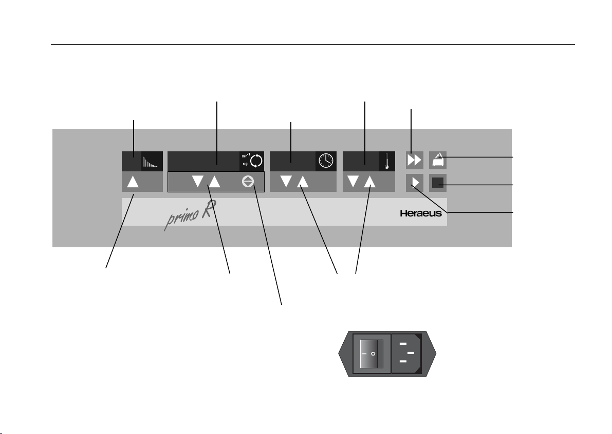
braking
profiles
speed/RCF
temperature
quick run
run time
"set" key
250009.597
0
Biofuge
"set" keys
rpm/RCF
display switch
"set" keys
open lid
stop
start
back panel
socket for mains cable
mains switch
Page 4

Control panel of the
Biofuge primo R
Display
Braking profiles
Continuous display : braking profile last used, 1 - 9;
2 - 9 = max. acceleration and various
braking profiles (2 [weak] to 9 [strong])
1 = slow acceleration and braking curve 2
Speed / RCF
During run: current rpm or RCF (after actuation of dis-
play switch)
End of run: "End"
Lid open: "OPEN"
(before start)
Lid open : "0" with flashing point
(rotor not yet recognized)
Error message: alternating display (if relevant)
Run time
Preselected time : remaining run time to 0
Continuous:
operation (hLd) run time passed (in hours, minutes)
"Quick run": run time passed (in minutes, seconds)
Temperature
During run: current sample temperature in °C
at temperature equilibrium)
Keys
Start: normal start
Stop: manual stop
Open lid: open lid (possible only with the instrument
switched on)
Quick run: short-term operation of the centrifuge as
long as key remains pressed
rpm/RCF
switch: switching between rpm and RCF display
"set" keys: stepwise increase/decrease of setpoint
values
Short pressing of any of the "set" keys: switch from current to
preset value, signaled by flashing display.
Error codes (troubleshooting see chapter
"Troubleshooting"):
E-00: motor blockage
E-03 speed measurement
E-08: overvoltage; overtemperature in the electronics
E-14: no rotor or rotor identification impossible
E-17: lid does not open
rotor: set speed higher than permissible speed
of the rotor
bAL: unbalance
Lid: lid opened or popped open during run
OPEN: with lid closed: safety circuit triggered
(drive overheated)
Page 5

Contents
Contents
For your safety............................................ 3
Proper use................................................................ 3
Improper use ............................................................ 3
Centrifuging hazardous materials ............................ 3
Handling ................................................................... 4
Conformity to current standards............................... 5
Safety instructions in this manual ............................ 5
The Biofuge primo R .................................. 7
Safety systems......................................................... 7
Properties................................................................. 8
Items delivered......................................................... 8
Functions and features............................................. 9
The "Easycontrol" user interface............................ 10
Rotor program and accessories.............. 13
Rotor program ........................................................ 14
Adapters................................................................. 16
Before use................................................. 19
Transport and installation....................................... 19
Proper location ....................................................... 19
Positioning the instrument .................................. 20
Mains connection ................................................... 20
Operation................................................... 21
Switching on the centrifuge.....................................21
Lid operation ...........................................................21
Opening the lid....................................................21
Closing the lid......................................................21
Inserting the rotor....................................................22
Handling of rotors and seals ...............................23
Important application information for rotor
7500 7599! ..........................................................24
Aerosol-tight application .........................................25
Permissible rotor temperature.............................26
Lifetime of the rotor .............................................26
Loading the rotor.....................................................27
Maximum loading................................................27
Filling the centrifuge tubes ..................................27
Loading instruction for rotors 7590 and 7595 .....28
Loading for aerosol-tight operation .....................28
Checking for aerosol tightness............................30
Placing the tubes in the rotor ..............................31
Entering parameters ...............................................32
Braking curves ........................................................32
Switching from speed to RCF display and vice versa
................................................................................32
Selecting the speed ................................................32
Entering the RCF value ..........................................33
Concerning the RCF value..................................33
1
Page 6

Contents
Selecting the run time............................................. 34
Preselected run time........................................... 34
Continuous operation ......................................... 34
Selecting the temperature ...................................... 35
Starting the centrifuge ............................................ 36
Unbalance detection............................................... 36
Changing the settings during the run ..................... 36
Stopping the centrifuge ..........................................37
Stopping with preset time ................................... 37
Stopping with continuous operation ................... 37
Temperature regulation at rest............................... 37
Short-time centrifugation ........................................ 38
Removing the rotor................................................. 38
Maintenance and care .............................. 39
Maintenance operations to be carried out by the
customer................................................................. 39
Cleaning.............................................................. 39
Disinfection ......................................................... 40
Disinfection with eau de Javelle .........................42
Autoclaving ......................................................... 42
The Service of KENDRO........................................ 43
Warranty conditions................................................ 43
Troubleshooting........................................45
Emergency lid release ............................................45
Problems you can handle yourself..........................47
In case you must call the Service ...........................54
Technical data.........................................................55
Electrical connections/fuses ...................................56
Appendix....................................................57
Braking and acceleration curves.............................57
Speed / RCF diagrams ...........................................59
Standard values for minimum sample temperature65
Autoclaving protocol for rotor 7500 7599................67
Index...........................................................69
2
Page 7

For your safety
For your safety
Heraeus centrifuges are manufactured according to
current technical standards and regulations. Nonetheless, centrifuges may pose dangers if
• they are not used as designed
• they are operated by untrained personnel
• their design is improperly changed
• the safety instructions are not heeded
Therefore anybody concerned with operation and
maintenance of the centrifuge must read and follow the safety instructions.
In addition, the pertinent regulations for prevention of
accidents must be strictly followed.
This manual is an integral part of the centrifuge assembly and must be kept close at
hand at all times.
Proper use
The centrifuge is designed to separate liquidsuspended materials having different densities and
particle size, respectively. The maximum sample density is 1.2 g/cm
3
at maximum speed.
Improper use
During a run, a safety zone of 30 cm around the centrifuge must be maintained where neither persons nor
hazardous materials may be stationed.
The centrifuge may cause harm to you or other persons and may damage material goods if you do not
respect the following safety measures:
Centrifuging hazardous materials
• The centrifuge is neither made inert, nor is it explo-
sion-proof. Therefore never use the centrifuge in an
explosion-prone environment.
• Explosive or flammable substances must not be
centrifuged. The same holds for substances prone
to react briskly with each other.
3
Page 8

For your safety
• Do not centrifuge toxic or radioactive substances or
pathogenic microorganisms unless you have taken
proper precautions.
Such precautions can e.g. consist of biological
seals.
• Should toxins or pathogenic substances enter the
centrifuge or its parts, you must carry out the proper
procedures for disinfection (see "Maintenance and
care – Disinfection").
• Strongly corrosive substances that may cause
damage to materials and impair the mechanical
strength of the rotor may be centrifuged only inside
protective vessels.
Handling
• Never use the centrifuge unless the rotor is properly
mounted.
• Never manually open the lid if the rotor still turns.
• Use only original parts for the centrifuge. The only
exception are common glass or plastic centrifuge
tubes if these are approved for the rotor speed and
RCF values of your rotor, respectively.
• Never use the centrifuge with the lid open.
• Never use the centrifuge if the paneling has been
partially or totally removed.
• Changes in mechanical or electrical components
may be carried out only by persons authorized to
this effect by KENDRO Laboratory Products.
• You may use the centrifuge only with a properly
loaded rotor. You must not overload the rotor.
• If the rotor or the lid shows visible traces of corro-
sion or wear, you must stop using it.
• Strictly follow the rules and regulations for cleaning
and disinfection.
4
Page 9
For your safety
Conformity to current standards
Heraeus centrifuges are manufactured and tested
according to the following standards and regulations:
for all voltages:
• IEC 1010-1 / EN 61010-1
• IEC 1010-2 / EN 61010-2-020
− Pollution degree 2
− Overvoltage category II
for 120 V only:
• CAN/CSA-C22.2 No. 1010.1-92
• CAN/CSA-C22.2 No. 1010.2.020-94
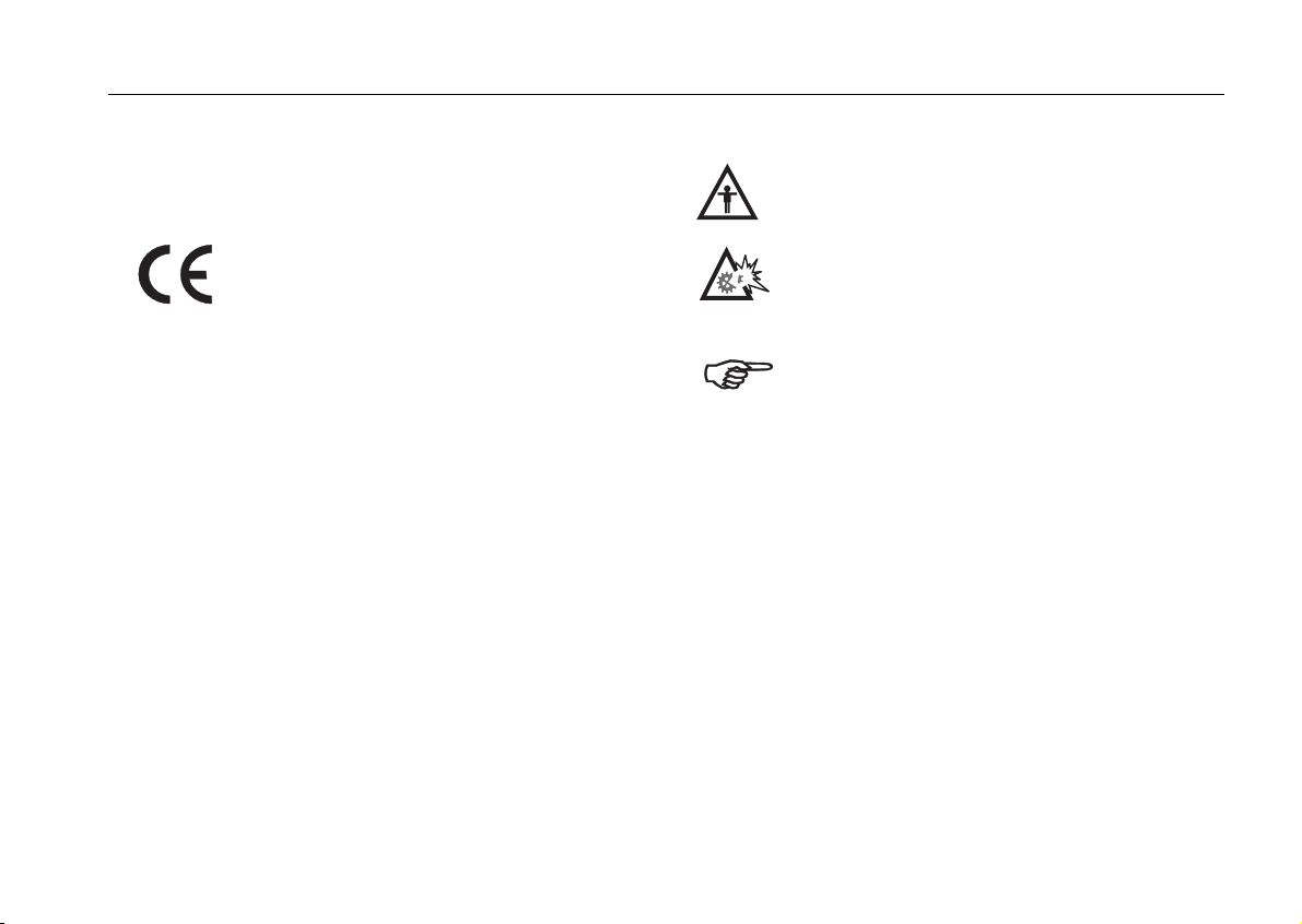
Safety instructions in this manual
This symbol denotes potential hazards to
persons.
This symbol denotes potential damage to
the centrifuge or parts in its immediate surroundings.
General hints are marked with this symbol.
In addition, you are asked to adhere to the pertinent
regulations, in Germany
• Regulations for prevention of accidents VBG 4
• Regulations for prevention of accidents VBG 5
• Regulations for prevention of accidents VBG 7z
• Regulations for prevention of accidents VBG 20
5
Page 10

For your safety
for your notes
6
Page 11
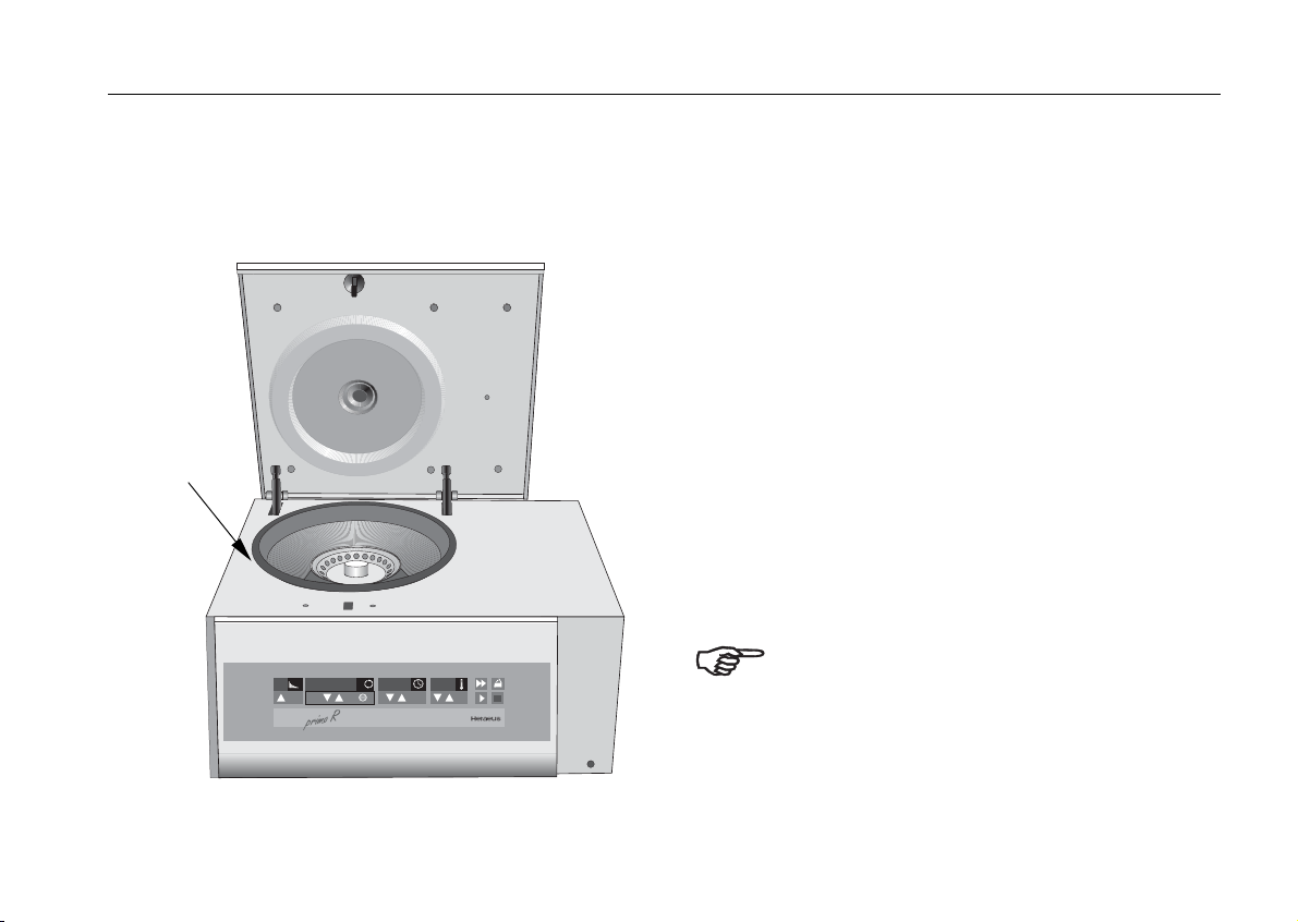
The Biofuge primo R
The figure below shows a general view of the Biofuge
primo R with open lid and the rotor put into place.
mains switch on
the back panel
-1
min
xg
0
Biofuge
The Biofuge primo R
Safety systems
The Biofuge primo R is equipped with a number of
safety systems:
• Housing and rotor chamber manufactured from
sheet steel; inner armoring made of steel, front
screen made from impact-resistant plastic
• Lid with window and lid lock
You can open the centrifuge lid only when the
power is turned on and the rotor has come to a halt.
You can start the centrifuge only if the lid is properly
locked.
• Rotor identification
• Electronic unbalance detection
• Emergency lid release: only in case of emergency,
e.g. during power failure (see chapter "Troubleshooting"
Do not tamper with the safety systems!
7
Page 12

The Biofuge primo R
Properties
The Biofuge primo R is a laboratory centrifuge for use
with a variety of rotors and a large number of commercially available centrifuge tubes.
The preset speed is reached in seconds. The maintenance-free induction motor provides quiet and vibration-free operation even at high speeds and warrants
an extremely long lifetime.
The user-friendly "Easycontrol" control panel permits
easy preselection of speed, RCF value, run time,
temperature and run profile (acceleration and braking
behavior). You can switch from speed to RCF display
or entry and vice versa.
You can change the set values even during a run.
With the "quick run" key (
sample for only a few seconds if that is required for
your particular task.
) you can centrifuge a
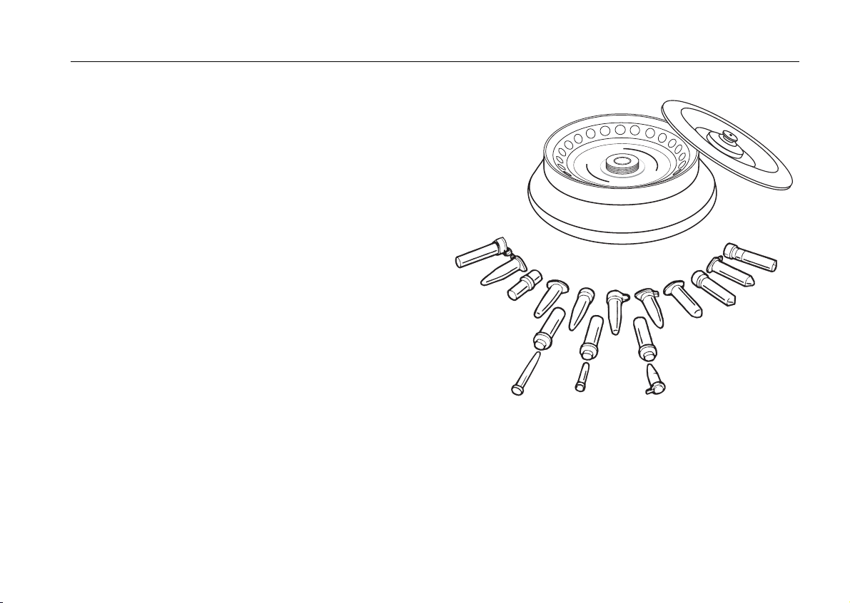
Items delivered
Items delivered with the centrifuge comprise:
− a special cap nut for fixing the rotor
− 10-mm tubular socket wrench for fastening the
cap nut
− power cord
− short operating instructions
The printed documents consist of the delivery notes
and this Manual.
cap nut
order no.
70056208
tubular socket
wrench
order no.
2036 0072
8
Page 13

Functions and features
Part / function Description / feature
design / housing galvanized sheet chassis with armored shell
tank stainless steel
drive induction drive without carbon brushes
key and display board key and display elements covered by an easy-care protective foil
control microprocessor-driven by Easycontrol II
main memory the data last entered remain in memory
functions RCF preselection, quick run
The Biofuge primo R
acceleration and braking
profiles
rotor identification automatic
unbalance detection electronic, effective as a function of rotor and speed
lid lock automatic locking following lid closure
2 acceleration and 8 braking profiles
9
Page 14

The Biofuge primo R
The "Easycontrol" user interface
Function Feature
lid opening
automatic unlocking via "open lid" key (
)
(unlocking in case of power failure: see chapter "Troubleshooting")
start
stop
"quick run" mode
start key (
stop key (
)
)
pressing the "quick run“ key (
) actuates maximum acceleration up to the
maximum permissible speed; upon key release centrifuge stops with maximum braking power
acceleration / braking profiles
1 = slow acceleration and braking curve 2,
2 ... 9 = fast acceleration and various braking curves (2=weak to 9=strong)
speed selection adjustable in steps of 10 min-1 within the range of 300 min-1 to 15000 min-1
RCF selection upon actuating the switchover key, the RCF value can be entered
run time selection
adjustable in minutes from 1 min to 9 h 59 min; "hLd" mode: permanent operation
run time display in "quick run" mode between 1 s and 60 s in seconds steps, above in minutes
temperature selection adjustable in 1 K steps from -9°C to +40°C
end of run speed display reads "End"
10
Page 15

Function Feature
The Biofuge primo R
diagnostic messages
• alternating display "rotor"/maximum speed or RCF
(acknowledgment by pressing the start key)
• incorrectly closed lid: display "OPEN"
• general instrument malfunction
(error messages with ERROR codes, see "Troubleshooting"
11
Page 16

The Biofuge primo R
for your notes
12
Page 17
Rotor program and accessories
Rotor program and accessories
The Biofuge primo R is delivered without rotor!
You may choose from among a large variety of rotors
available as accessories.
(see Rotor program, Table 1)
In addition, there are sets of adapters and reduction
sleeves for diverse commercially available vessels (see
Adapters, Table 2).
Please consult our sales documentation for a complete
collection of accessories including technical data and
order numbers.
3
1
1
2
4
1
1
1
5
1
6
1
d
7
2
4
x
1
4
8
g
1
9
p
p
2
1
0
/
9
6
2
#
1
3
3
2
2
2
3
1
S
m
T
a
N
0
x
E
1
M
l
o
U
a
R
T
9
S
N
I
S
8
U
E
A
7
R
E
H
6
m
p
r
5
0
2
0
4
0
3
1
4
x
a
m
3
2
4
2
1
13
Page 18

Rotor program and accessories
Rotor program
Table 1: Rotor program (1)
Rotor designation
order no.
fixed-angle rotor
6 x 50 ml Falcon
swinging bucket
rotor 4 x 100
rotor 12 x 1.5 / 2.0
7500 7590 7500 7591 7500 7592
buckets and caps see Table 2
maximum permissible load [ g ] 6 x 130 4 x 200 12 x 4
maximum speed n
maximum RCF value at n
[ min-1 ] 8,500 4,000 13,000
max
10,015 2,525 16,438
max
radius max./min. [ cm ] 12.4 / 6.0 14.1 / 5.0 8.7 / 4.7
angle [ ° ] 45 90 90
acceleration/braking time [ s ] 55 / 36 26 / 21 42 / 42
min. temperature at nmax [ °C ]*
* relative to room temperature 23°C
k factor [ S × h ]
- 1 - 9 4
2.545 16.801 3.690
aerosol-tight yes (reduced filling) yes no
permissible temperature range
autoclavable (number of cycles)
14
–
121 °C; (unlimited)
–
no
–
no
swinging bucket
Page 19

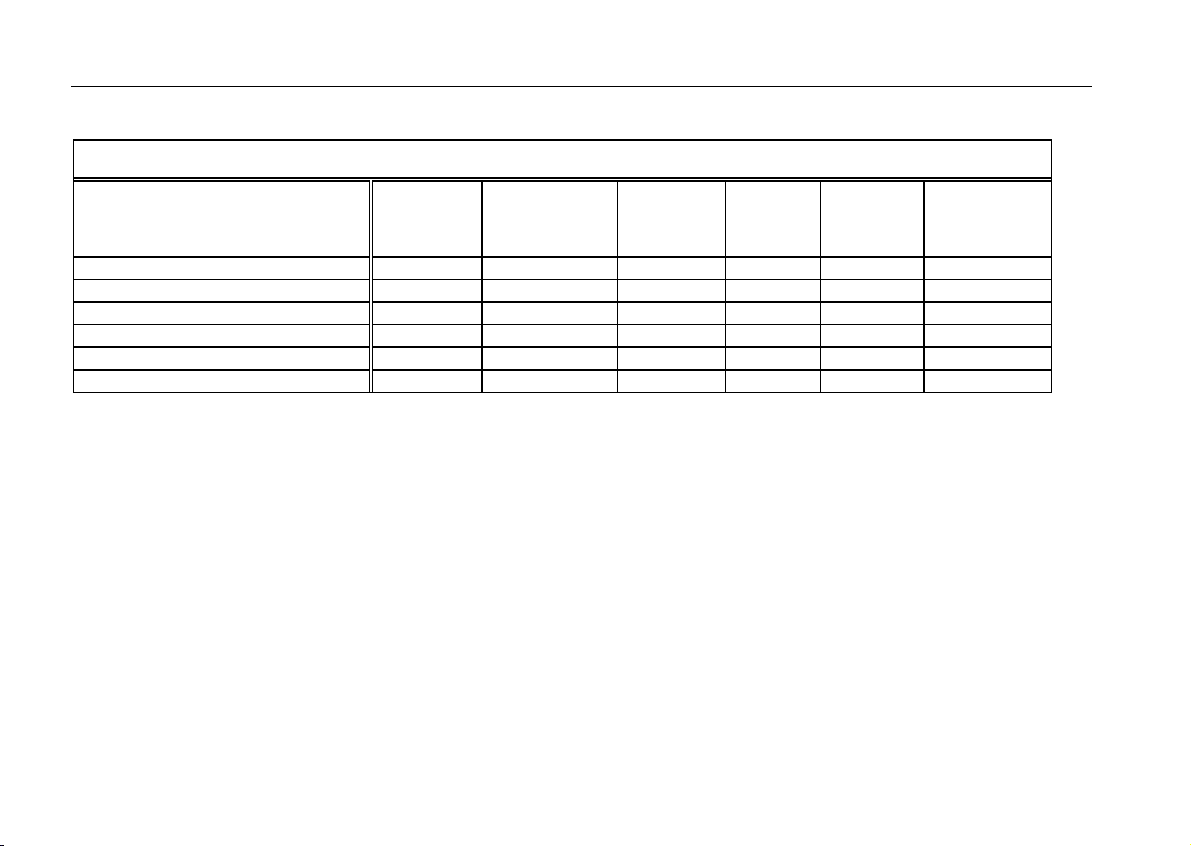
Rotor program
Table 1: Rotor program (2)
Rotor program and accessories
Rotor designation microliter rotor
24 x 2 ml aluminum
microliter rotor 24 x
2 ml Polypropylene
drum rotor
order no.
7500 7593 7500 7599 7500 7595
maximum permissible load [ g ] 24 x 4 24 x 4 8 x 80
maximum speed n
maximum RCF value at n
[ min-1 ] 15,000 13,000 12,000
max
21,882 16,060 14,005
max
radius max./min. [ cm ] 8.7 / 5.9 8.5 / 5.9 8.7 / 3.8
angle [ ° ] 45 40 90 / 60
acceleration/braking time [ s ] 35 / 22 16 / 20 41 / 33
min. temperature at nmax [ °C ]*
* relative to room temperature 23°C
k factor [ S × h ]
5 -3 4
437 547 1.457
aerosol-tight yes (reduced filling) yes (reduced filling) no
permissible temperature range
autoclavable (number of cycles)
–
121°C; (unlimited)
-4 °C to +40 °C
121°C; (10 cycles)
–
no
15
Page 20

Rotor program and accessories
Adapters
Table 2: Adapters (1)
Adapters for fixed-angle rotor
7500 7590
max. vessel size
∅ x length
[ mm ]
number
per
adapter
number
per
rotor
color order no.
1.5 ml microvessels 11 x 57 4 24 7600 2905
3.5 ml 11 x 100 4 24 7500 3091
6.5 ml 13 x 113 2 12 7500 3092
12 ml 16 x 95 2 12 7500 3093
16 ml 18 x 122 1 6 7600 2906
38 ml 25 x 112 1 6 7500 3094
50 ml 29 x 122 1 6 7500 3014
15 ml Falcon 16.5 x 120 1 6 7500 3095
50 ml Falcon 30 x 117 1 6 7500 3096
Adapters for microliter rotor
7500 7593 / 7500 7599
max. vessel size
∅ x length
vessel capacity
[ ml ]
number
per set
color order no.
[ mm ]
reduction sleeve PCR 6.2 x 20 0.2 24 gray 7600 3750
reduction sleeve 8 x 43.5 0.5 / 0.6 24 turquoise 7600 3758
reduction sleeve 6 x 46 0.25 / 0.4 24 red 7600 3759
16
Page 21
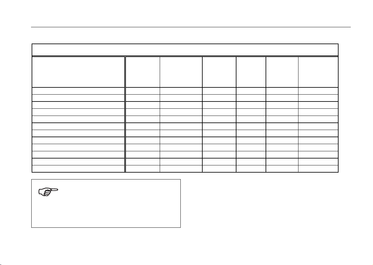
Table 2: Adapters (2)
Rotor program and accessories
Buckets and adapters for
swinging bucket rotor 7500 7591
incl.
rubber
buffer
max.
vessel size
∅ x length
number
per
adapter
number
per
rotor
color order no.
[ mm ]
Roundbucket 100 ml/50 ml conical 1807 44 x 100 – – – 7500 7555
1.5 / 2 ml micro vessels 11 x 42 10 40 white 7500 7547
7 ml DIN 1818 12 x 102 5 20 white 7500 7545
7 ml DIN blood sampling 1818 13 x 105 3 12 white 7500 7546
15 ml DIN blood sampling 1803 17 x 102 3 12 white 7500 7544
25 ml DIN 1804 25 x 110 1 4 white 7500 7543
50 ml DIN 1805 35 x 105 1 4 white 7500 7542
adapters 50 ml - Falcon 30 x 117 – – – 7500 7556
adapters 15 ml - Falcon 16.5 x 120 1 4 white 7500 7557
hermetic caps 7500 7598
The rubber pads 7600 1807 are
only to be used for centrifuging
100 ml glass containers.
Remove the rubber pads when
using adapters.
17
Page 22
Rotor program and accessories
Table 2: Adapters (3)
Racks for
drum rotor 7500 7595
1.5 ml microvessels 10 80 yellow 7600 1499
1.5 / 2 ml microvessels 10 80 red 7600 1244
1.5 / 2 ml microvessels (60°) 6 48 white 7500 1498
0.3 ml microcapillary vessels 8 64 blue 7600 1246
0.5 / 0.6 ml microvessels 15 120 green 7600 1247
0.25 / 0.4 ml microvessels 20 160 yellow 7600 1248
18
number
per
adapter
number
per
rotor
color order no.
Page 23
Before use
Transport and installation
The centrifuge is delivered in an special box. Cut it
open and remove the protective material.
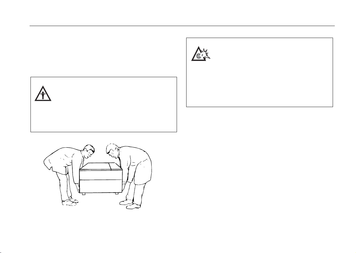
When transporting the centrifuge, consider its weight (see Technical Data);
always grab it on both sides taking
care that enough helpers are around
(see Figure).
Do not lift by the front panel!
Before use
Damage to the centrifuge by jolting
during transport and sudden dropping!
Transport the centrifuge only in the
upright position using the special
box provided with the instrument,
and secure it properly. Place the centrifuge carefully.
Proper location
The centrifuge may only be used indoors. Its location
must meet the following criteria:
• A safety zone of at least 30 cm around the centri-
fuge must be maintained where hazardous materials
may not be kept during centrifugation.
• The substructure must be stable and resonance-
free. A good support is provided by a plane laboratory bench or a large laboratory carriage with lockable casters.
• To ensure sufficient air circulation, a minimum dis-
tance from the wall of 10 cm at the back and of 15
cm on each side must be kept.
19
Page 24
Before use
• The centrifuge must be protected from heat and
direct sunshine.
• The location must be well ventilated at all times.
Positioning the instrument
Following a relocation, the centrifuge must always be
properly aligned with the adjustable bases.
Make sure the bases are evenly weighted.
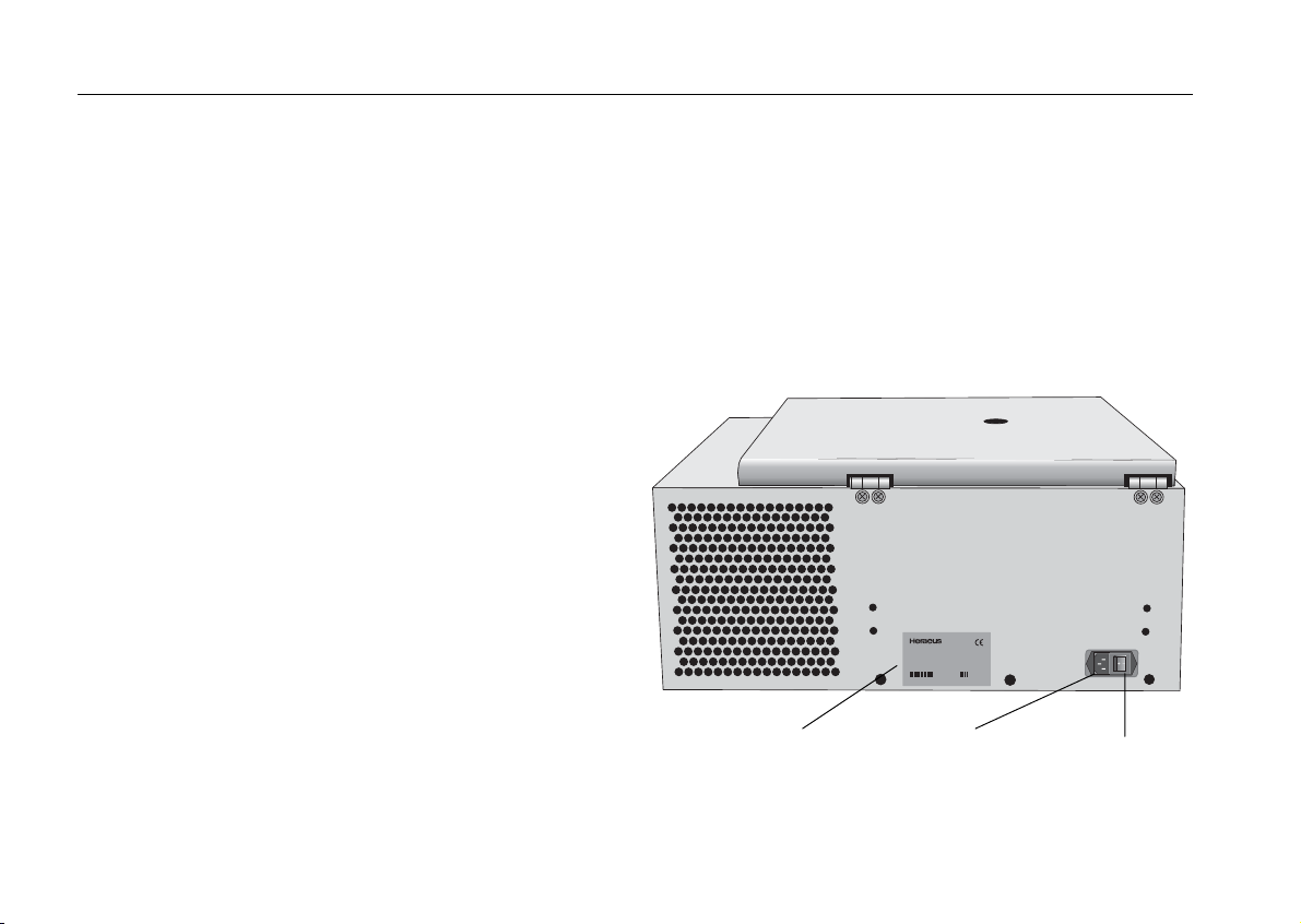
Mains connection
Connect the centrifuge only to an earthed mains supply. Make sure that the cable is compatible with the
safety regulations valid in your country, and that your
mains voltage and frequency correspond to the specifications on the instrument label.
Turn the mains switch on the back panel off (press "0");
only then connect the centrifuge with the mains supply
via the power cord.
D-37520Osterode
MadeinGermany
INSTRUMENTS
Baujahr:
max.Drehzahl:
sieheRotor
kin.Energie:1NNN Nm
Spannung:
220V~
Fabr.-Nr.:
Frequenz:
50/60Hz
Bestell-Nr.: 7500NNNN
Strom: NN
,A
Leistung: NNN
zulässigeDichtedesFüllgutes:N,N kg/cm
W
3
mains switch type plate with indication
of voltage and frequency
Biofugeprimo R
socket for
power cord
20
Page 25

Operation
Operation
Switching on the centrifuge
Turn on the mains switch on the back of the instrument.
For a couple of seconds the following reading appears
in the control panel:
8.8.8.8.8. 8.8.8.88.8.8.
0
Biof uge
This tells you that the instrument carries out an internal
check of its software (see table on page 54).
After this check the display switches to the actual values. The values for the remaining run time and speed
both read 0. The display of the acceleration/braking
curve depends on the value last set.
The following figure gives an example of possible readings. A detailed description of possible settings is given
below in this chapter.
0
Biofuge
090.007
Lid operation
Opening the lid
Press the "open lid" key
If the message "Lift Lid" appears, you must lift the lid
slightly.
(Emergency release in case of malfunction or power
failure: see chapter "Troubleshooting".)
Closing the lid
The centrifuge is closed by slightly pressing down the
front part of the lid.
Do not slam the lid shut!
.
21
Page 26

Operation
Inserting the rotor
Improper or improperly combined
accessories may cause severe damage to the centrifuge!
The rotors approved for the Biofuge primo R are detailed in the chapter "Rotor program and accessories".
Use only rotors with this instrument that are contained
in this list.
To insert the rotor, you need the cap nut and the tubular socket wrench supplied (see chapter "The Biofuge
primo R – Items delivered".
Possible damage to drive and rotor!
You may insert the rotor only if the
temperature of the drive, the rotor and
the cap nut is between 10 °C and 30 °C.
Proceed as follows:
1. Open the lid and make sure that the rotor chamber
and the rotor are clean. Remove eventual dust, foreign material or sample residues. The thread and
the O-Ring on the motor shaft must be in perfect
condition.
2. Turn the rotor so that the notch for engaging the
drive shaft points downward.
3. Place the rotor on top of the drive shaft so that the
notch of the rotor is located precisely above the retaining pin.
4. Push the rotor gently down until the thread is completely laid bare (see figure).
22
Page 27

Operation
5. If you have placed the rotor correctly, you can
screw on the cap nut easily and secure it with the
tubular socket wrench delivered with the instrument.
6. Place the rotor cap onto the rotor.
Do not push the rotor down using
force. If you cannot screw on the cap
nut, you must carefully lift off the rotor
and insert it again.
Regularly check the proper positioning of
the rotor and re-tighten the cap nut as
needed.
Handling of rotors and seals
The swiveling pegs of the swinging bucket rotors and
the corresponding notches of the buckets must be
lightly greased.
(Lubricant 7600 3500 is delivered with the rotor.)
The O rings in the rotors and rotor lids as well as the O
ring in the hermetic cap 7500 7598 for the 100-ml / 50ml buckets must likewise be lightly greased.
Use only the special lubricant
7600 3500 for greasing the O rings!
You must replace damaged O rings!
Replacements parts are delivered with the rotor or can
be ordered separately as spare part package.
– 7500 3404 for the rotor 7500 7593
– 7500 3423 for the rotor 7500 7590
23
Page 28

Operation
Important application information for rotor
7500 7599!
To attach the rotor, use the acorn nut with ball head!
(Order no. 70056208)
To tighten the acorn nut, use the 10 mm tubular hexa-
gon box spanner.
(Order no. 20360072)
Please always close your microlitre containers care-
fully. Open container lids can damage the rotor lid.
For some special applications the container lids must
remain unsealed. If this is the case, please use the
screw top (order no. 75003326) instead of the standard
snap-on lid (order no. 70901111).
A) Position the snap-on lid.
Press the rotor lid down onto the rotor until
the snap-on catch engages onto the ball
of the acorn nut.
B) Remove the snap-on lid.
By activating the grip cap, the lock is released and the rotor lid can be removed.
24
Page 29

Operation
Aerosol-tight application
The following steps have to be carried out:
• Lubricate the seals before inserting them (lubricant
order no. 75003500)
• Insert the seal (C profile) in the groove at the side
of the body of the rotor.
• Insert the O-ring into the inner groove on the
screw-on top.
only with screw-on top 75003326
and not with open container lids!
Attention :
Please check that your sample containers are suitable
for the centrifugal application desired.
(16060 x g ; temperature in uncooled devices approx.
10 K above room temperature)
Please observe the permissible filling volumes!
Nominal volume: Permissible volume:
2.0 ml - 1.5 ml
1.5 ml - 1.0 ml
others The sealing elements are to be checked regularly for
damage to the shape and surface!
Exchange faulty parts immediately (spare sealing rings
75003268)
The snap-on lid is not suitable for
aerosol-tight application!
2
/3 nominal volume
25
Page 30

Operation
Permissible rotor temperature
The rotor 7500 7599 may be used only
within a temperature range of
-4 °C to +40 °C. Pre-cooling in the
freezer is not permitted.
Lifetime of the rotor
There are no restrictions to the service life of the high
performance rotor 7500 3325 B. However please observe the following due to safety reasons:
Rotors and accessories made of
plastic should not be exposed to
direct sunlight and UV rays!
If the rotor shows signs of discoloration, deformation or wear, or is out
of balance it must be exchanged
straight away!
26
Page 31

Operation
Loading the rotor
Maximum loading
Overloading may cause the rotor to
explode! Exploding parts may severely damage the centrifuge!
The Biofuge primo R can reach high rotational speeds
implying enormous centrifugal force. The rotors are
designed in a way warranting sufficient residual
strength even at the highest permissible speed.
However, this safety system presupposes that the
maximum permissible load of the rotor is not exceeded.
If you wish to centrifuge samples that together with the
adapters exceed the maximum permissible load, you
must either reduce the sample volume or calculate the
permissible speed n
mula:
n
perm
n= ∗
max
according to the following for-
perm
maximum permissible load
actual load
Filling the centrifuge tubes
Check carefully whether your sample
vessels are permissible for the respective g value, and reduce the
speed if necessary.
The smaller the unbalance of the centrifuge, the better
the separation since separated zones are no longer
perturbed by vibration. It is therefore important to balance the centrifuge tubes as well as possible.
Please note that the lifetime of plastic tubes,
particularly at the highest permissible load
(speed, temperature), is limited; they must be
replaced if worn!
27
Page 32

Operation
Loading instruction for rotors 7590 and 7595
You must always equip all sample
locations with adapters or sample
racks!
The rotor 7590 may only be used with
the lid in place.
Loading for aerosol-tight operation
For the centrifugation of hazardous
samples you must always respect the
highest permissible sample amounts.
Aerosol-tight operation presupposes that sample vessels are properly filled and the rotor lid is correctly
closed.
The vessels may generally be filled only to a point
where the sample cannot reach the vessel rim during
centrifugation. For the most commonly used vessels,
the maximum allowed volumes are listed in the table on
page 29.
For the fixed-angle rotors you should use the special
hexagon screw driver for tightening (and loosening) the
lid in order to safeguard proper closure (push through
the bore of the screw-on lid.)
28
Page 33

Operation
Rotor vessel type / maximum filling volume
leakage
test
microliter rotor
24 x 1.5 ml #7593
microliter rotor
24 x 2.0 ml #7599
fixed-angle rotor
6 x 50 ml #7590
Reakt 1.5 ml
1.0 ml
Reakt 1.5 ml
1.0 ml
Falcon 50 ml
49 ml
Reakt 2.0 ml
1.5 ml
Reakt 2.0 ml
1.5 ml
Falcon 15 ml
14 ml
8 ml
8 ml
*
swinging bucket rotor #7591
Glas 100 ml
80 ml
Glas 50 ml
45 ml
*) Vessel filled to the brim, lid screwed on lightly
• Reakt – reaction vessel
• Falcon – bucket type Falcon
• Glas – glass vessel
29
Page 34

Operation
Checking for aerosol tightness
Check the aerosol tightness of your
rotor whenever appropriate.
Since you cannot yourself carry out the
check with the swinging bucket rotor
#7591, you should monitor seals, sealing surfaces and screw caps particularly carefully in this case!
To carry out the test, proceed as follows:
• Carefully clean and degrease the rotor chamber
wall, then attach an adhesive white paper strip
(about 4 x 2 cm) so that liquid leaking out of the rotor may precipitate on it.
• Fill all places of the respective rotor with water
according to the following Table. Insert the rotor
into the centrifuge and fasten it.
• Carefully place the amount of test liquid (0.5 %
sodium fluorescein in water) specified in the column “leakage test” into the lower part of the rotor
within a virtual circle comprising the vessel bores
(not the bores themselves) using a pipette or syringe.
• Place the rotor lid on top and screw it on.
ATTENTION: Make sure that there is no spilled
test liquid on the rotor (clean if necessary)!
• Carry out a test run for 10 minutes at maximum
rotor speed and 23 °C ambient temperature.
• Check the paper strip under UV light (preferentially
in a darkened room):
If there is no detectable fluorescence, the test is
considered passed.
• Finally rinse rotor, rotor lid and lid seal in running
water and allow to dry.
30
Page 35

Placing the tubes in the rotor
The rotor must be loaded symmetrically. When loading
the rotor only partially, you must ensure that opposite
bores always receive tubes of equal weight (when centrifuging a single sample, place a centrifuge tube e.g.
filled with water opposite). The following figure gives
examples for proper loading.
Operation
Uneven loading can in the extreme
case lead to actuation of the unbalance detection. Unbalance not only
causes a noisy run, but also rapidly
damages the drive.
3
1
1
2
4
1
1
1
5
1
1
S
m
T
a
N
0
6
x
E
1
l
M
o
U
a
d
1
R
T
2
7
9
S
4
N
x
I
1
4
S
8
1
9
2
0
2
1
8
g
U
E
A
7
p
R
p
E
H
1
/
6
9
6
m
#
p
r
3
5
3
0
2
0
4
0
2
3
1
2
x
4
a
m
2
3
3
2
4
2
1
3
1
1
2
4
1
1
1
5
1
1
S
m
T
a
N
0
6
x
E
1
l
M
o
U
a
d
1
R
T
2
7
9
S
4
N
x
I
1
4
S
8
1
9
p
p
2
0
2
1
8
g
U
E
A
7
R
E
H
1
/
6
9
6
m
#
p
r
3
5
3
0
2
0
4
0
2
3
1
2
x
4
a
m
2
3
3
2
4
2
1
3
1
1
2
4
1
1
1
5
1
1
S
m
T
a
N
0
6
x
E
1
l
M
o
U
a
d
1
R
T
2
7
9
S
4
N
x
I
1
4
S
8
8
g
U
E
1
A
9
7
p
R
p
E
H
2
1
0
/
6
9
6
m
2
#
p
1
r
3
5
3
0
2
0
4
0
2
3
1
2
x
4
a
m
2
3
3
2
4
2
1
3
1
1
2
4
1
1
1
5
1
1
S
m
T
a
N
0
6
x
E
1
l
M
o
U
a
d
1
R
T
2
7
9
S
4
N
x
I
1
4
S
8
8
g
U
E
1
A
9
7
p
R
p
E
H
2
1
0
/
6
9
6
m
2
#
p
1
r
3
5
3
0
2
0
4
0
2
3
1
2
x
4
a
m
2
3
3
2
4
2
1
3
1
1
2
4
1
1
1
5
1
1
S
m
T
a
N
0
6
x
E
1
l
M
o
U
a
d
1
R
T
2
7
9
S
4
N
x
I
1
4
S
8
8
g
U
E
1
A
9
7
p
R
p
E
H
2
1
0
/
6
9
6
m
2
#
p
1
r
3
5
3
0
2
0
4
0
2
3
1
2
x
4
a
m
2
3
3
2
4
2
1
3
1
1
2
4
1
1
1
5
1
1
S
m
T
a
N
0
6
x
E
1
l
M
o
U
a
d
1
R
T
2
7
9
S
4
N
x
I
1
4
S
8
1
9
2
0
2
1
8
g
U
E
A
7
p
R
p
E
H
1
/
6
9
6
m
#
p
r
3
5
3
0
2
0
4
0
2
3
1
2
x
4
a
m
2
3
3
2
4
2
1
3
1
1
2
4
1
1
1
5
1
1
S
m
T
a
N
0
6
x
E
1
l
M
o
U
a
d
1
R
T
2
7
9
S
4
N
x
I
1
4
S
8
1
9
p
p
2
0
2
1
8
g
U
E
A
7
R
E
H
1
/
6
9
6
m
#
p
r
3
5
3
0
2
0
4
0
2
3
1
2
x
4
a
m
2
3
3
2
4
2
1
These examples are to be applied to the other rotors in
an analogous manner!
After placing the tubes, close the rotor lid.
wrong loading
proper loading
31
Page 36

Operation
Entering parameters
Braking curves
The Biofuge primo R offers a total of 9 running profiles
for optimally centrifuging samples and gradients.
Please consult the diagram examples in the Appendix
for a closer look at the acceleration and braking curves
(for rotors not mentioned there you may extrapolate the
respective values).
After switching the centrifuge on, the centrifugation
profiles last entered are preselected.
By pressing the "set" key
the subsequent profiles until the desired profile is
reached.
Once the display stops flashing, the value is stored in
memory and remains unchanged until changed by a
new entry.
Switching from speed to RCF display and
vice versa
Upon turning the centrifuge on, the speed display is the
default setting.
Use the speed/RCF display switch to choose between
speed and RCF entry or display.
you can switch through
Selecting the speed
The centrifuge can be set to a minimum of 300 and a
maximum of 15,000 min
You can adjust the speed in steps of 10 min
as follows:
1. By pressing once one of the "set" keys
increase) or
tion of the control panel, you switch from actual to
setpoint values. The value last stored is displayed,
with the digit to be entered flashing (if there is no
value stored in memory, this is indicated by dashes
-----).
2. By briefly pressing the input key you can now raise
0
15000
3. If you keep the key pressed, the display changes at
first slowly and after a few seconds at an accelerated pace.
4. Release the key as soon as you have reached the
desired value, and fine tune if necessary by repeatedly pressing the key. The decimal place flashes for
-1
(depending on the rotor).
-1
. Proceed
(for an
(for a decrease) in the "speed" sec-
or lower the speed by
one step (10 min
-1
).
32
Page 37

Operation
a number of seconds, then changes to permanent
display. The speed is now stored.
5. For faster operation, you may shift the flashing cursor in the speed/RCF and in the run time panels:
just press both and simultaneously. The cursor moves by one digit to the left for each key depression.
Entering the RCF value
You can adjust the RCF setpoint in steps of 1. The
setpoint is entered analogously to the speed.
As long as the rotor has not been identified, it is impossible to display RCF values. This is signaled by dashes
----- in the display.
Shortly after starting the centrifuge run the rotor is identified, and the current value is displayed.
NOTE:
If you set an extremely low RCF value, this may be
automatically corrected if the resulting speed would be
lower than 300 rpm.
Concerning the RCF value
The relative centrifugal force (RCF) is given in multiples of the earth gravity g. It is a dimensionless number
that allows one to compare the efficiency of separation
or sedimentation of diverse instruments, since it is
independent of the instrument used. The only values
entered in the equation are radius and speed of centrifugation:
2
n
RCF
.
1000
r=∗
∗1118
r = radius of centrifugation in cm
n = speed in rpm
The maximum RCF value is based on the maximum
radius of the vessel bore.
Please note that this value becomes lower
depending on the tubes and adapters used.
You may take this into account when calculating the
RCF value for your application.
33
Page 38

Operation
Selecting the run time
You can select a run time between 1 min and 9 h 59
min or continuous operation (hLd).
Preselected run time
To set a fixed run time, proceed as follows:
1. Press one of the "set" keys
(for a decrease) in the "time" section of the con-
trol panel once to switch from the actual to the setpoint mode.
2. By briefly pressing the input key you can now raise
or lower the run time in 1-
2.30
3. If you keep the selected key pressed, the display
changes at first slowly and after a few seconds at
an accelerated pace.
minute steps.
(for an increase) or
4. Release the key as soon as you have reached the
desired value, and fine tune if necessary by repeatedly pressing the key.
The minute display flashes for a number of seconds, then changes to permanent display. The run
time is now stored.
You may shift the flashing cursor to set the value as
described under "Selecting the speed".
Continuous operation
To switch the Biofuge primo R to the continuous mode,
you must press the key
"hLd".
With this setting, the centrifuge keeps running until
stopped manually.
until the display reads
34
Page 39

Operation
Selecting the temperature
You can preselect the temperature in the range of
-9 °C to +40 °C.
(Please consult the standard diagram in the Appendix
to obtain the attainable values.)
To adjust the temperature, proceed as follows:
1. Press one of the "set" keys
(for a decrease) in the "temperature" section of
the control panel once to switch from the actual to
the setpoint mode.
2. By briefly pressing the input key you can now raise
or lower the temperature in 1-K
7
steps.
3. If you keep the selected key pressed, the display
changes at first slowly and after a few seconds at
an accelerated pace.
(for an increase) or
4. Release the key as soon as you have reached the
desired value, and fine tune if necessary by repeatedly pressing the key.
The temperature display flashes for a number of seconds, then changes to the current value display. The
temperature setpoint is now stored.
35
Page 40

Operation
Starting the centrifuge
Once the rotor is properly placed, the mains switch is
turned on and the lid is closed, you can start the centrifuge.
Press the "start" key
fuge accelerates to the preselected value. Simultaneously, the run time display starts going backward from
the preset time, at first giving the remaining run time in
minutes and upon reaching the last minute in seconds
(in continuous operation the time display goes forward).
If a value exceeding the maximum permissible speed
or RCF of the respective rotor was entered, this is indicated after the start of the centrifuge by the alternately
flashing messages "rotor" and the maximum permissible value for the inserted rotor.
Within 15 seconds you may adopt this value by again
pressing the "start" key; the centrifugation is then continued. Otherwise the centrifuge stops, and you must
enter a permissible value.
You cannot open the lid during the run.
in the control panel. The centri-
Unbalance detection
In case there is an unbalance in the rotor, this is indicated at a speed slightly exceeding approximately 300
rpm by the message "bAL".
The run is terminated, and you may restart the centrifuge after correcting the error (check loading).
Changing the settings during the run
You can change all settings during a run. By pressing
once any one of the "set" keys in the control panel you
can switch from the actual to the setpoint mode.
The setting to be adjusted flashes and can then be
altered. Once the data input is finished and the display
has changed to the actual value display mode, the new
settings become operative.
36
Page 41

Operation
Stopping the centrifuge
Stopping with preset time
Normally the run time has been preselected, and all
you have to do is wait until the centrifuge terminates
the run automatically at the end of the preset time.
As soon as the speed is down to zero, the display
reads "End". You can now open the centrifuge by
pressing the "open lid" key
ples.
You can manually stop the centrifuge at any time by
pressing the "stop“ key
At this point the remaining run time is displayed.
Stopping with continuous operation
If you have chosen continuous operation, you must
stop the centrifuge manually. Press the "stop" key
the control panel. The centrifuge starts braking with the
preset braking profile. The display reads "End", and
you can open the lid by pressing the "open lid" key
and remove your samples.
and remove your sam-
.
in
Temperature regulation at rest
The precise control becomes active once the rotor has
been identified; the speed panel then displays "End".
If the rotor has not been identified (lid has been closed
and the "start" key
speed panel reads "0" with flashing point), the instrument regulates the temperature so that the samples
cannot freeze in any one of the usable rotors.
If you find the systematic deviation of up to 4 K bothersome, you must start the rotor for a short period until it
is identified.
has not yet been pressed,
37
Page 42

Operation
Short-time centrifugation
For short-term operation, the Biofuge primo R is
equipped with a "quick run" function.
Short-term centrifugation is started by pressing the
"quick run" key
key is released.
In this mode the centrifuge accelerates with full power
up to the maximum speed. The preset speed or RCF is
ignored in this case.
During acceleration the time is counted forward in seconds. The display remains until the centrifuge lid is
opened.
continuously; it stops as soon as the
Depending on the rotor, the centrifuge
accelerates to the maximum speed!
Check carefully whether you have to
maintain a specific speed for your
application.
Removing the rotor
To remove the rotor, you must follow the steps described for insertion in reverse order.
Grab rotor with both hands and pull
upwards perpendicularly.
1. Open the centrifuge lid.
2. Remove the rotor lid.
3. Unscrew the cap nut by turning it counterclockwise
using the socket wrench supplied, and remove the
cap nut.
4. Grab the rotor with both hands and lift it carefully off
the drive shaft. Make sure not to tilt it.
When using an aerosol-tight lid, you may in case of
contamination separate the pertinent rotors from the
drive shaft without opening the lid!
In this case you can e.g. open and decontaminate the
dismantled rotor using a safety work bench.
38
Page 43

Maintenance and care
Maintenance and care
Maintenance operations to be carried out
by the customer
For the protection of persons, the environment and the
equipment you are obliged to clean the centrifuge regularly and to disinfect it if necessary.
Unsuitable cleaning agents or disinfection procedures may damage the
centrifuge and its parts!
For cleaning and disinfection use only
the cleaning and disinfection procedures detailed in this manual.
Cleaning
Pull mains plug before cleaning the
instrument!
The main care is to clean regularly (or as need arises)
the housing, the rotor chamber, the rotor and the accessories. This is indicated both for reasons of hygiene
and to prevent corrosion due to contamination sticking
to the instrument and its accessories.
For cleaning you should only use agents approved by
KENDRO:
− Caraform
− deconex 16 NT
− Extran MA 02 neutral
− RBS neutral
For all other cleaning agents please consult our Service Department!
39
Page 44

Maintenance and care
Organic solvents decompose the lubricant of the motor bearing. The drive
shaft may jam.
Liquids and especially organic solvents must not come into contact with
the drive shaft and the ball bearing
during cleaning.
If an ice sheet was present in the inner
chamber, make sure to remove the water
formed during defrosting.
Disinfection
Infectious material may enter the centrifuge if the vessel fractures or in the
case of spillage.
Risk of infection if touched!
Note the permitted filling volumes!
In the event of contamination, the user
must ensure that no third parties are
in danger!
Parts affected must be decontaminated immediately.
Note the personnel safety measures!
If necessary, further safety measures
must be taken.
If a centrifuge tube containing infectious material becomes leaky or breaks during a run, you must immediately disinfect the centrifuge. In doing this, you must
heed the following points:
40
Page 45

Maintenance and care
• To decontaminate the affected rotor chamber and
rotor, use only disinfectants approved by KENDRO.
These agents are to be used according to the Instructions for Use supplied with the respective disinfectant:
− Aldasan 2000
− Carlitt Spray
− Coldspore
− Gigasept FF
− HBV Pump-Spray
− Incidin Liquid Spray
− Incidur Spray
− Incidin plus
− Kohrsolin iD
− Lysetol FF
− Lysoform
− Lysoformin 3000
− Sagromed
− Sagrotan
For all other disinfectants please consult our Service
Department!
• You may disinfect the rotor and the accessories as
described in the following section. Be sure to follow
the pertinent safety procedures for handling infectious material.
1. Pull the mains plug.
2. Unscrew the rotor seat.
3. Grab the rotor with both hands and pull it perpen-
dicularly off the drive shaft.
4. Remove the centrifuge tubes and adapters, and
disinfect them or dispose of them as necessary.
5. Treat the rotor and the rotor lid according to the
instructions given for the disinfectant in question
(soaking in liquid or spraying). You must strictly observe the specified reaction times!
6. Turn the rotor head down and drain it. Thoroughly
rinse rotor and lid with water.
7. Dispose of the disinfectant solution as required by
the respective valid regulations.
8. Aluminum rotors must subsequently be treated with
anticorrosive grease.
41
Page 46

Maintenance and care
Disinfection with eau de Javelle
These bleaching agents contain extremely aggressive
hypochlorite solutions and may in no case be used with
aluminium rotors. To protect the rotor 75007599 as far
as possible you must take the following precautions:
1. Avoid high temperatures!
The bleaching solution and the rotor should not be
warmer than ca. 25 °C.
2. Do not let the bleaching solution act longer than
absolutely necessary!
3. After disinfection, rinse the rotor thoroughly with
distilled water and allow to dry.
Autoclaving
Check whether autoclaving is permitted!
(See note in Table 1 starting on page 14 and labels on
rotor body and rotor lid.)
You may autoclave the rotor and the adapters at
121 °C.
Maximum permissible autoclaving cycle: 20 min at
121 °C.
For reasons of safety you may autoclave the rotor 7500 7599 maximally 10
times!
The rotor must be cleaned and rinsed with distilled
water before being autoclaved. Remove the rotor lid,
the centrifuge tubes and the adapters. Place plastic
rotors on an even surface to avoid deformation.
Chemical additives to the steam are not permitted.
Never exceed the maximum permissible values for autoclaving temperature
and autoclaving time.
Should the rotor show signs of wear,
you must stop using it!
42
Page 47

Maintenance and care
The Service of KENDRO
Kendro Laboratory Products GmbH recommends annual servicing of the centrifuge and the accessories by
the authorized service or skilled personnel. The service
provided by KENDRO comprises checking:
• the electrical installation
• the suitability of the location
• the lid lock mechanism and the safety circuit
• the rotor
• the rotor fastening and the drive shaft
Defective parts are exchanged. Besides, the service
personnel cleans the rotor chamber.
KENDRO offers inspection and service contracts covering these benefits. Inspection costs are charged as
flat-rate contracts.
Necessary repairs are carried out free of cost during
the warranty period, and against payment after expiration of the warranty.
Warranty conditions
The warranty period starts with the day of delivery.
Within the warranty period the centrifuge is repaired or
replaced free of cost if there are demonstrable faults in
materials or workmanship.
Conditions for a warranty are that:
• the centrifuge is used according to the instructions
of use
• installation, additions, adjustments, changes or
repairs are carried out exclusively by personnel authorized for this by KENDRO
• the required maintenance and care procedures are
carried out regularly.
43
Page 48

Maintenance and care
for your notes
44
Page 49

Troubleshooting
Troubleshooting
Emergency lid release
In case of a power failure you cannot open the lid normally using the normal electrical lid unlocking mechanism. To permit unloading even in this case, the centrifuge is equipped with a manual lid unlocking system.
However, you may use this system only in case of
emergency.
Rotor can spin at high speed! Touching
it may cause severe injuries!
Always wait for several minutes until
the rotor has come to a complete stop.
Without power the brake does not function, and braking takes much longer
than normal!
Proceed as follows:
1. Make sure that the rotor stands still (consult window
in the lid).
Never brake the rotor using your hands
or tools!
2. Unplug the mains plug.
3. Near the front panel of the housing there is a plastic
plug underneath the instrument that you can pry out
of the bottom plate using a screw driver or a knife.
By suddenly pulling the attached rip cord you can
activate the mechanical lid unlocking mechanism.
The lid opens, and you can remove your samples.
45
Page 50

Troubleshooting
4. Finally, push the rip cord back into the instrument
and close the opening with the plastic plug.
Once the power is back, you can connect the instrument to the mains supply and turn it on.
46
Page 51

Problems you can handle yourself
If problems other than those described in the following tables arise, you must consult the authorized
service.
Error
Behavior of the
centrifuge
Troubleshooting
Possible causes and corrective measures
Displays
remain dark
Displays fail
briefly.
The motor stops.
The rotor stops without
braking.
The lid cannot be
opened.
The motor stops
suddenly.
The rotor stops without
braking.
The display reads E-14.
Mains failure or not connected.
1. Is the mains switch turned on?
2. Check the mains connection.
3. If the mains connection is OK, call the nearest Service.
Brief interruption of mains supply.
1. Turn off mains switch.
2. Check whether the plug is plugged in properly.
3. Restart the centrifuge.
47
Page 52

Troubleshooting
Error
Lid cannot be
opened.
–
Behavior of the
centrifuge
Pressing the "open lid"
key has no effect.
Centrifuge is
exceptionally noisy.
Possible causes and corrective measures
Lid not correctly engaged or lid warped.
1. Check whether mains connection is OK and the instrument
switched on (displays lit).
2. Press lid down in the middle of the front section once, and actuate
the "open lid" key anew.
(Each additional actuation of "open lid" key requires a waiting time
of about 4 seconds.)
3. If this is unsuccessful, you may open the lid using the emergency
lid release (see page 45).
1. Stop the centrifuge by pressing the "stop" key
, in case of
emergency pull mains plug.
2. Wait until the centrifuge stands still.
3. Check whether the rotor is properly loaded.
4. Check whether a broken vessel, damage to the rotor or motor
malfunction was responsible for the noise.
If you cannot locate and solve the problem, call Service.
48
Page 53

Troubleshooting
Error
Message "bAl"
appears in
display.
Message
"rotor"
appears in
display.
Display
"OPEN"
appears
although lid is
closed.
Behavior of the
centrifuge
Rotor stops without
braking.
Rotor decelerates with
brake on following a
pause.
Start impossible.
Possible causes and corrective measures
Unbalance switch actuated.
1. Open the instrument by pressing "open lid" key ..
2. Check whether the rotor is properly loaded.
3. Check whether a broken vessel or damage to the rotor was
responsible for unbalance switch actuation.
Set speed exceeds permissible maximum speed for the rotor in
question. (The same holds for RCF setting.)
A) For about 15 sec. the display shows alternately "rotor" and the
maximum permissible speed or RCF for the inserted rotor. Within
this period, it is possible to adopt this value by again pressing the
"start" key. The centrifugation is then continued.
B) Following onset of braking you must wait until the rotor has
stopped. By opening and closing the lid you can reset the
message "rotor". After entering a permissible speed you can start
anew.
Lid not properly closed.
Open the lid and repeat locking procedure.
49
Page 54

Troubleshooting
Error
Message "Lid"
appears in the
display.
E-00
E-02
E-03
Behavior of the
Possible causes and corrective measures
centrifuge
Drive stops.
Rotor coasts to rest.
Lid was opened manually during the run.
1. Press the lid shut again. The instrument stops without braking.
2. If you want to continue the run, you must switch the instrument off
and on again.
Motor does not start. Motor or rotor blocked.
1. Switch instrument off and on again using the mains switch.
2. Open the lid.
3. Check whether the rotor can turn freely.
If you cannot thus relieve the malfunction, call our Service.
Rotor stops without
Internal program error in memory.
braking to standstill.
Switch the instrument off and on again. If the error persists, call our
Instrument cannot be
operated.
Rotor stops without
Service.
Error in speed measurement.
braking to standstill.
Switch the instrument off and on again. If the error persists, call our
Instrument cannot be
operated.
Service.
50
Page 55

Troubleshooting
Error
E-04
E-06
E-07
E-08
Behavior of the
centrifuge
Rotor stops without
braking to standstill.
Instrument cannot be
operated.
Rotor stops without
braking to standstill.
Instrument cannot be
operated.
Rotor stops without
braking to standstill.
Lid can be opened.
Rotor stops without
braking to standstill.
Instrument cannot be
operated.
Possible causes and corrective measures
Temperature measurement impaired (probe breakage).
Switch the instrument off and on again. If the error persists, call our
Service.
Communication error between keyboard and main processor.
Switch the instrument off and on again. If the error persists, call our
Service.
Overtemperature in the tank.
Display > 51°C or measured temperature > 70°C .
(Possibly refrigeration unit defective)
Overvoltage at the U/F converter.
Mains voltage outside tolerance. Brake resistance defective. Call
Service if trouble persists
51
Page 56

Troubleshooting
Error
E-10
E-12
E-14
E-15
Behavior of the
centrifuge
During self test after
switching on.
Rotor stops without
braking to standstill.
Instrument cannot be
operated.
Instrument does not start
or brakes to standstill.
Rotor stops without
braking to standstill.
Instrument cannot be
operated.
Possible causes and corrective measures
NV-RAM; error in program memory.
Switch the instrument off and on again. If the problem persists, call
Service.
Temperature measurement impaired.
Switch the instrument off and on again. If the problem persists, call
Service.
No rotor present or rotor identification impossible.
A) Check whether a certified rotor is inserted.
B) Following a brief power failure, the rotor could not be identified.
Switch the instrument off and on again using the mains switch.
Check sum in NV-RAM wrong.
52
Page 57

Troubleshooting
Error
Behavior of the
centrifuge
E-17 Lid does not open.
E-19
During self test after
switching on.
E-22
During self test after
switching on.
E-24
During self test after
switching on.
E-25
Rotor stops without
braking to standstill.
Possible causes and corrective measures
Lid blocked or jammed.
Press the front part of the lid centrally down once, and press the
"open lid" key anew.
Otherwise see "Emergency lid release" (page 45)
Wrong NV-RAM or keyboard.
NV-RAM parameter incompatible with processor
NV-RAM 2 absent.
Start without rotor.
1. Turn instrument off and on again.
2. Open the instrument by pressing the "Open lid" key
..
3. Check whether the rotor is loaded and placed correctly.
4. Check whether a broken vessel or a damaged rotor was
responsible for actuating the unbalance switch.
If the error persists, call Service.
53
Page 58

Troubleshooting
In case you must call the Service
Should you need our Service, please tell us the order
no. and serial number of your instrument. You find the
pertinent information at the back of the instrument near
the socket for the mains plug.
Moreover it is helpful for our service technician to know
the software version. You can determine the software
version as follows:
1. Switch the instrument off.
2. Switch the instrument on.
All displays read 8.88888… for about one second.
Subsequently, the display may show e.g. the follow-
ing readings for 2 seconds each:
Software version keyboard
Software version
NV-RAM version 1
NV-RAM version 2
The values in the time panel give the development
stage.
__591 __2
__590 __6
_2571 __7
_2572 __2
The last information displayed is the current cycle
status.
Cycle counter
__235 _CY
The values given are only examples!
During the subsequent program test, the message
_ TEST PRO 9 ... 0 is displayed.
54
Page 59

Technical data
Function/parameter Value
Technical data
environmental conditions
- indoor use
- max. elevation 2000 m above sea level
- max. relative humidity 80 % up to 31 °C; linearly decreasing down
to 50 % relative humidity at 40 °C.
permissible temperature of the environment +2 °C to +40 °C
run time 1 min - 9 h 59 min, hold = permanent operation
maximum speed n
minimum speed n
15,000 min
max
300 min-1
min
maximum RCF value at n
21,885
max
-1
(rotor-dependent, adjustable in steps of 10)
maximum kinetic energy <10 kNm
noise at maximum speed < 60 dB (A)
set temperature range -9 °C to +40 °C
dimensions (H x W x D) 313 mm x 580 mm x 493 mm
weight without rotor 69.5 kg
55
Page 60

Technical data
Function/parameter Value
compliance with standards
Manufactured and checked in accordance with
EN 61 010-1, EN 61 010-2-020, EN 50 081-1, EN 50 082-1.
Electrical connections/fuses
Order no. Voltage Frequency
7500 5440 230 V 50 / 60 Hz 2.9 A 490 W 4.0 A 10 AT
7500 5441 120 V 60 Hz 7.4 A 680 W 8.0 A 10 AT
Nominal
current
Power
consumption
Fuse protection
of instrument
Fuse protection of building
56
Page 61

Appendix
Braking and acceleration curves
Acceleration curves
4000
3000
]
-1
2000
speed [min
1000
0
0 20 40 60 80 100
Braking curves
Appendix
92
1
time [s]
57
Page 62

Appendix
]
-1
speed [min
4000
3000
2000
1000
+
21
5
6
8
9
7
3
4
0
0 50 100 150
58
time [s]
Page 63

Speed / RCF diagrams
100000
75007590 fixed-angle rotor 6 x 50 ml (Falcon)
RCF (r
= 12,4 cm)
max
RCF (r
= 6,0 cm)
min
Appendix
10000
1000
RCF
100
10
1
100 1000 10000 100000
speed [min
-1
]
n
= 8500 min-1
max
RCF (r
max
, n
max
) = 10015
59
Page 64

Appendix
RCF
10000
1000
100
10
75007591 swinging bucket rotor 4 x 50 ml (Falcon) / 4 x 100 ml
RCF (r
= 14,5 cm)
RCF (r
max
= 5,0 cm)
min
n
= 4000 min-1
max
RCF (r
max
, n
) = 2584
max
60
1
100 1000 10000
speed [min-1]
Page 65

Appendix
75007592 swinging bucket rotor 12 x 1,5 / 2,0 ml
RCF (r
= 8,7 cm)
RCF (r
max
= 4,7 cm)
min
100000
10000
1000
n
= 13000 min-1
100
RCF
max
RCF (r
max
, n
) = 16438
max
10
1
100 1000 10000 100000
speed [min-1]
61
Page 66

Appendix
100000
75007593 fixed-angle rotor 24 x 1.5 / 2 ml
RCF (r
= 8,7 cm)
RCF (r
max
= 5,9 cm)
min
62
10000
RCF
1000
n
= 17000 min-1
max
RCF (r
max
, n
max
) = 28106
100
10
1
100 1000 10000 100000
-1
speed [min
]
Page 67

Appendix
75007599 microliter rotor 24 x 1.5 / 2 ml
RCF (r
RCF (r
= 8,5 cm)
max
= 5,9 cm)
min
100000
10000
1000
n
= 13000 min-1
RCF
100
max
RCF (r
max
, n
max
) = 16058
10
1
100 1000 10000 100000
-1
speed [min
]
63
Page 68

Appendix
100000
75007595 drum rotor 80 x 2 ml
RCF (r
= 8,7 cm)
RCF (r
max
= 3,8 cm)
min
64
RCF
10000
1000
n
= 13000 min-1
100
max
RCF (r
10
1
100 1000 10000 100000
speed [min
-1
]
max
, n
max
) = 16436
Page 69

Standard values for minimum sample temperature
Appendix
Rotor #7590/6x Falcon 50ml
(relativ e to room t emperature 23°C)
0
-5
min. tem perature (°C )
-10
6000 6500 7000 7500 8000 8500
speed (m in-1)
Rotor #7595/Trommel
(relativ e t o room tem perature 23°C )
5
0
-5
min. t emperature (°C)
-10
8000 9000 10000 11000 12000
speed (m in-1)
Rotor #7593/24x2ml Alu
(relativ e t o room tem perature 23°C )
5
0
-5
min. t emperature (°C)
-10
9000 11000 13000 15000
speed (min-1)
Rotor #7599/24x2ml PP
(relativ e t o room tem perature 23°C )
0
-5
min. tem perature (°C )
-10
10000 11000 12000 13000
speed (m in-1)
65
Page 70

Appendix
Standard values for minimum sample temperature
66
Page 71

Autoclaving protocol for rotor 7500 7599
Date Remark Operator Signature
1
2
3
4
5
6
7
8
9
10
Appendix
67
Page 72

Appendix
for your notes
68
Page 73

Index
A
acceleration curves 57
acceleration profiles 8, 10
acceleration time 14, 15
accessories 13
cap nut 8
tubular socket wrench 8
adapters
fixed-angle rotor 16
microliter rotor 16
adjustable bases
for leveling 20
aerosol tightness
check 30
aerosol-tight 14, 15
aerosol-tight operation
maximum allowed volumes 28
agents
for cleaning 39
aluminium rotors
anticorrosive grease 41
angle rotor 14
anticorrosive grease
for aluminium rotors 41
Index
approved rotors 22
autoclaving 42
autoclaving cycle
permissible maximum 42
autoclaving protocol
rotor 7500 7594 67
B
bleaching agents
for disinfection 42
braking curves 32
Braking curves 57
braking profiles 8, 10
braking time 14, 15
buckets
swinging bucket rotor 17
C
cap nut
for fixing rotor 8
centrifuge tubes 8
filling 27
changing settings
69
Page 74

Index
during run 36
cleaning 39
closing the lid 21
conditions of warranty 43
continuous operation 34
control panel
readings 8
corrosive substances
protective vessels for 4
cursor
shifting 33
D
damage
symbol for potential 5
dangerous chemicals 3
diagnostic messages 11
disinfectants
approved 41
disinfection 4, 40
procedure 41
with eau de Javelle 42
display 21
displays
brief failure 47
not lit 47
drum rotor 15
racks 18
E
Easycontrol
user interface 8
Easycontrol user interface 10
EC Guidelines 5
electrical connections 56
emergency lid release 45
error codes
„Lid“ 50
error codes
„bAl“ 49
E-00 50
E-02 50
E-03 50
E-04 51
E-06 51
E-07 51
E-08 51
E-10 52
E-12 52
E-14 52
E-15 52
E-17 53
E-19 53
E-22 53
70
Page 75

Index
E-25 53
Message "rotor" 49
OPEN with lid closed 49
error messages 11
F
features 9
filling
centrifuge tubes 27
fixed-angle rotor 14
fluorescein
test solution for aerosol tightness 30
formula
maximum permissible load 27
frequency 20
functional properties 9
fuses 56
H
hazardous substances 3
hazards
symbols used for 5
hints
symbol for 5
hypochlorite solutions
for disinfection 42
I
icons
for denoting dangers and potential damage 5
indoor use 19
infectious material
precautions in case of tube breakage 40
inserting the rotor 22
installation 19
items delivered 8
K
k factor 14, 15
Kendro
Service 43
L
lid
blockage 48
lid opening 10
Lid operation 21
71
Page 76

Index
lid unlocking mechanism
manual 45
lifetime
plastic tubes 27
loading
for aerosol-tight operation 28
maximum 27
rotors 7590 and 7595 28
location 19
lubrication
O-Rings 23
swinging bucket rotors 23
M
mains connection 20
mains switch 20
maintenance 39
manual lid unlocking 45
manual stopping 37
maximum allowed volumes
for aerosol-tight operation 28
maximum filling volume
aerosol-tight operation 29
maximum loading 27
maximum permissible load
formula for 27
maximum permissible RCF 36
maximum permissible speed 36
maximum sample density 3
microliter rotor 15
min. temperature 14, 15
minimum distance
from wall 19
minimum sample temperature
standard values 65, 66
N
noisy operation 48
O
opening the lid 21
operation
short-time 38
organic solvents
not allowed for cleaning 40
original parts
mandatory use 4
O-Rings
lubrication 23
overloading
dangers implied 27
72
Page 77

Index
P
parameters
entry 32
partial loading
of rotor 31
pathogenic microorganisms
protection against 4
permissible speed 27
plastic tubes
limited lifetime 27
positioning 20
preselection
temperature 35
problems
handling of 47
protective vessels
for corrosive substances 4
Q
quick run function 38
quick run mode 8, 10
R
radius 14, 15
radius of centrifugation
for calculation of RCF value 33
RCF
maximum 36
RCF / speed diagrams 59
RCF display 32
and rotor identification 33
RCF selection 10
RCF setpoint 33
RCF value 8, 14, 15, 33
readings
of control panel during run 8
relative centrifugal force 33
rip cord
manual lid unlocking 45
rotor
cap nut for fixing 8
loading 31
partial loading 31
removal 38
rotor cap 23
rotor identification 7, 33
and RCF display 33
rotor insertion 22
temperature 22
tools for 22
73
Page 78

Index
rotor program 14
rotor temperature
permissible 26
rotors
approved 22
run profile 8
run time
range 34
setting 34
run time display
during run 36
run time selection 10
running profiles 32
S
safety instructions 3, 4
safety measures 3
safety standards 5
safety systems
built-in 7
safety zone 3, 19
sample density
maximum 3
sample temperature
minimum 66
selection
temperature 35
74
service contracts
Kendro 43
setting
run time 34
temperature 35
settings
change during run 36
short-time operation 38
socket wrench 8
sodium fluorescein
test solution for aerosol tightness 30
software check
internal 21
software version
determination 54
speed
maximum 36
permissible 27
speed / RCF diagrams 59
speed display 32
speed of centrifugation
for calculation of RCF value 33
speed selection 10, 32
speed setting 32
speed/RCF display
switch 32
standard values
minimum sample temperature 65
stopping
manually 37
Page 79

Index
with continuous operation 37
with preset time 37
substructure 19
swinging bucket rotor 14
adapters 17
buckets 17
swinging bucket rotors
lubrication 23
switching
from RCF to speed display and vice versa 32
symbols
for hazards and dangers 5
T
technical data 55
temperature
samples 66
temperature regulation
at rest 37
temperature selection 10
time
counted forward in quick run mode 38
time display
during run 36
tools for inserting rotor 22
toxins
protection against 4
transport 19
precautions for 19
tube
breakage with infectious material 40
tubes
for centrifugation 8
U
unbalance 27
unbalance detection 7, 31, 36
user interface 10
Easycontrol 10
V
voltage 20
W
warranty conditions 43
75
Page 80

Kendro Laboratory Products GmbH
Postbox 15 63
D-63405 Hanau / Germany
Telephone:
(+49) 1805 / 53 63 76
Telefax:
(+49) 61 81/ 3 57 49, Sales
(+49) 55 22/ 31 62 76, Service
Telephone:
(+49) 55 22/ 31 62 22, Service
In the interest of continuous product
development, we reserve the right to make
changes without express notice.
20056884 Primo R_UK 03/01
Printed in Germany
 Loading...