

Page 1
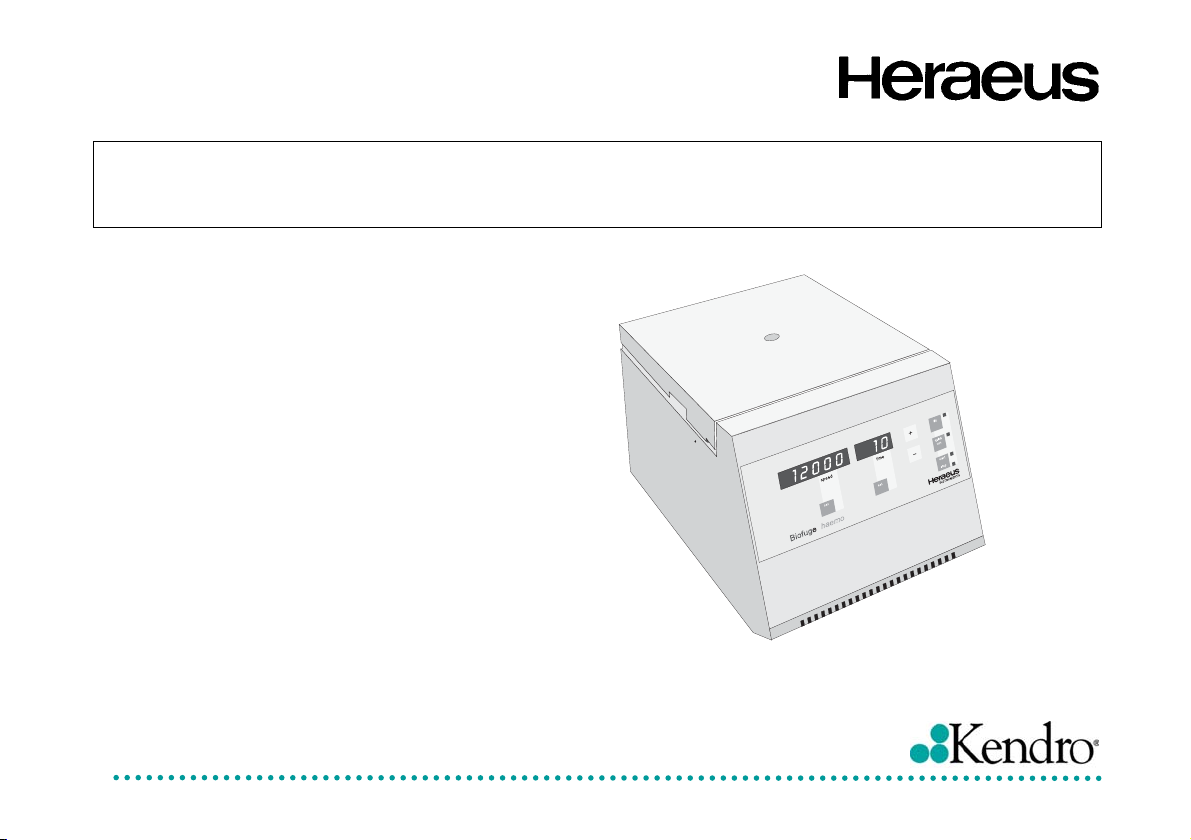
Biofuge haemo
Instructions for use
Page 2

How to use this manual
Use this manual to get acquainted with your centrifuge and its accessories.
The manual helps you to avoid inappropriate handling. Make sure to keep it always close to the centrifuge.
A manual that is not kept handy cannot provide
protection against improper handling and thus
against damage to persons and objects.
The manual comprises chapters on
• Safety regulations
• Instrument description
• Rotor program and accessories
• Transportation and hook-up
• Use of the centrifuge
• Maintenance and care
• Troubleshooting
• Technical data
• Index
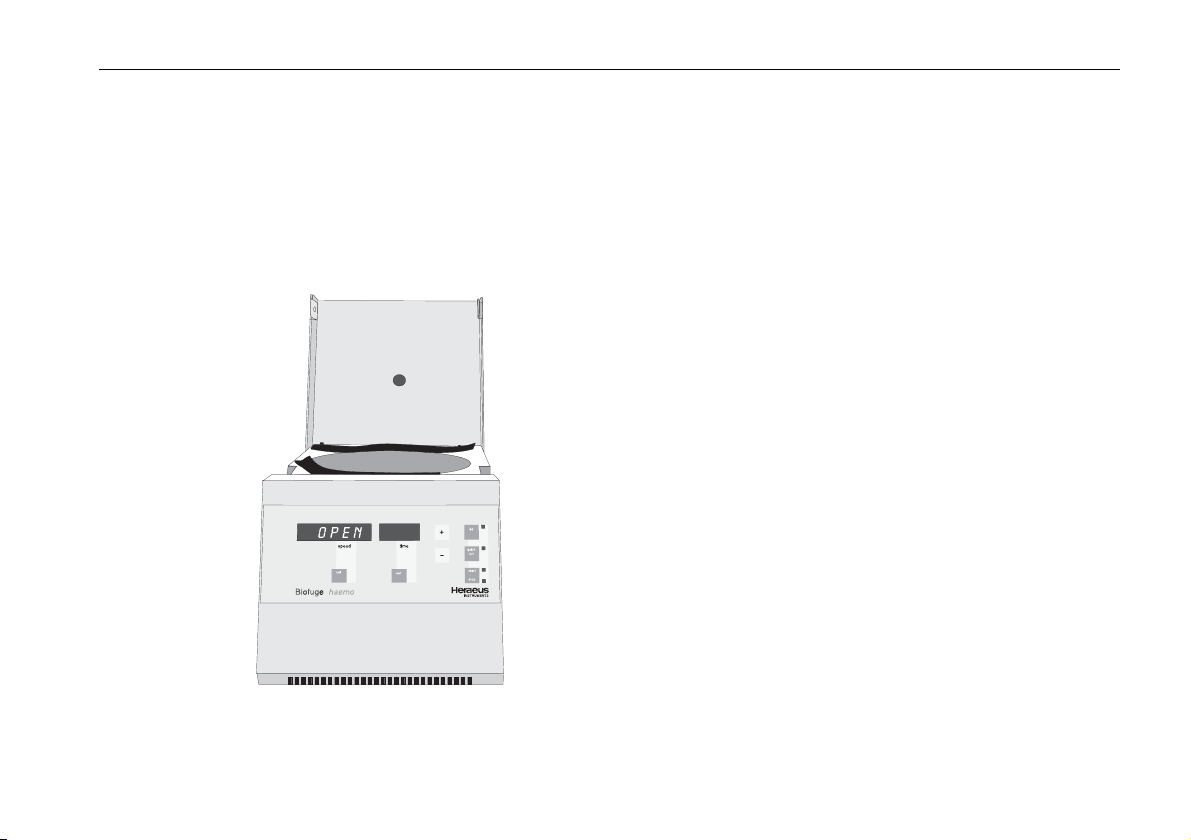
Overleaf you will find a graphic repre-
sentation of the control panel of the
Biofuge haemo with a survey of the
most important functions
Please fold out
Page 3

12000
speed time
10
-
+
set
Biofuge
haemo
set
lid
quick
run
start
stop
INSTRUMENTS
Page 4

The control panel of the
Biofuge haemo
Display
Speed
Resting state: upon pressing any key: display of
preselected speed, after 2 min switch
to standby mode (flashing red light)
During run: preselected speed
Braking: "br"
End: "0"
Lid open: "OPEN"
Resting/end: error codes (if present)
Run time ("time")
Resting/end: upon pressing any key: display of
preselected run time, after 2 min
switch to standby mode (flashing red
light)
During run: remaining run time or (with quick start)
run time passed
Keys
lid: open lid (only possible if connected
with mains supply)
quick run: short-term acceleration as long as key
is pressed, with indication of run time
passed
start/stop: normal start or manual stop
set speed/time: selection of the parameter to be
changed (speed or run time)
+/- stepwise increase/decrease of preset
values for the selected parameter
speed or run time, accelerated
change when pressed permanently
Error codes
(troubleshooting see chapter "Troubleshooting")
E-1/E-12: keys do not respond (main board defective)
E-3: no braking current: lid popped open or
manually opened during run; excess tem-
perature in the drive
br: power turned off during run or power failure
lid: lid opened during run
OPEN: lid lock mechanism out of order
Page 5

Contents
For your safety........................................... 3
Proper use............................................................... 3
Improper use ........................................................... 3
Centrifuging hazardous materials ........................... 3
Handling .................................................................. 4
Conformity to current standards.............................. 5
Safety instructions in this manual ........................... 5
The Biofuge haemo ................................... 7
Safety systems........................................................ 7
Rotor chamber..................................................... 7
Lid lock mechanism............................................. 7
Properties................................................................ 8
"Quick run" operation .............................................. 8
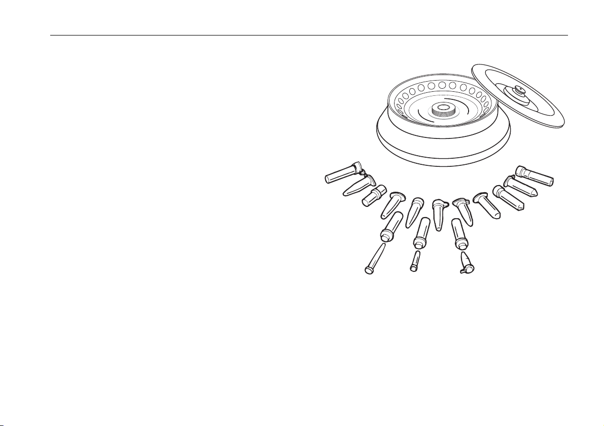
Accessories ............................................... 9
Standard accessories ............................................. 9
Hematocrit dish and reading harp ....................... 9
Reading spiral ..................................................... 9
Hematocrit rotor................................................. 10
Fixed-angle rotor 7500 3325 for microliter tubes11
Fixed-angle rotor: technical data....................... 12
Adapters for rotor order no. 7500 3325............. 13
Other accessories ............................................. 13
Contents
Before use ................................................ 15
Where to install the centrifuge...............................15
Mains connection................................................... 15
Removing the transport protection ........................ 15
Operation.................................................. 17
Transport and installation ......................................17
Mains connection................................................... 17
Opening the lid.......................................................18
Emergency lid release .......................................18
Loading the hematocrit rotor..................................19
Inserting the hematocrit rotor.................................19
Important application information for
rotor 7500 3325 ! ..................................................21
Inserting the rotor ..................................................22
Permissible rotor temperature ...........................23
Lifetime of the rotor ............................................ 23
Removing the rotor ................................................ 24
Loading the rotor ...................................................24
Maximum loading...............................................25
Filling the tubes..................................................25
Aerosol-tight application ........................................26
Please observe the permissible filling volumes! 26
Checking for aerosol tightness ..........................27
Placing the tubes in the rotor.................................28
1
Page 6

Contents
Selecting the speed............................................... 29
Selecting the run time ........................................... 30
Preselected run time.......................................... 30
Continuous operation ........................................ 30
Starting the centrifuge ........................................... 31
Changing the settings during the run .................... 32
Displaying the preset values ................................. 32
Stopping the centrifuge ......................................... 32
Stopping with preset time .................................. 32
Stopping with continuous operation .................. 34
Short-time centrifugation ....................................... 34
RCF value ............................................................. 35
Measuring the hematocrit value ............................ 36
Reading harp ..................................................... 36
Reading spiral.................................................... 36
General hints concerning hematocrit
measurements................................................... 36
Maintenance and care ............................. 38
Maintenance to be performed by the customer .... 38
Cleaning............................................................. 38
Disinfection ........................................................ 39
Decontamination................................................ 41
Autoclaving ........................................................ 42
The KENDRO service offer ................................... 43
Warranty conditions .............................................. 43
Troubleshooting.......................................44
Problems you can handle yourself ........................44
In case you must call the Service ..........................46
Technical data .......................................... 48
Component parts and performance.......................48
Electrical connections/fuses ..................................51
Speed / g diagram for rotor 7500 3325..................52
Autoclaving protocol ..............................................53
Index.......................................................... 54
2
Page 7

For your safety
For your safety
Heraeus centrifuges are manufactured according to
current technical standards and regulations. Nonetheless, centrifuges may pose dangers if
• they are not used as designed
• they are operated by untrained personnel
• their design is improperly changed
• the safety instructions are not heeded
Therefore anybody concerned with operation and
maintenance of the centrifuge must read and follow
the safety instructions.
In addition, the pertinent regulations for prevention of
accidents must be strictly followed.
This manual is an integral part of the centrifuge assembly and must be kept close at
hand at all times.
Proper use
The centrifuge is designed to separate liquidsuspended materials having different densities and
particle size, respectively. The maximum sample density is 1.2 g/cm
3
at maximum speed.
Improper use
During a run, a safety zone of 30 cm around the centrifuge must be maintained where neither persons nor
hazardous materials may be stationed.
The centrifuge may cause harm to you or other persons and may damage material goods if you do not
respect the following safety measures:
Centrifuging hazardous materials
• The centrifuge is neither made inert, nor is it explo-
sion-proof. Therefore never use the centrifuge in an
explosion-prone environment.
• Explosive or flammable substances must not be
centrifuged. The same holds for substances prone
to react briskly with each other.
3
Page 8

For your safety
• Do not centrifuge toxic or radioactive substances or
pathogenic microorganisms unless you have taken
proper precautions.
Such precautions can e.g. consist of biological
seals.
• Should toxins or pathogenic substances enter the
centrifuge or its parts, you must carry out the proper
procedures for disinfection (see "Maintenance and
care – Disinfection").
• Strongly corrosive substances that may cause dam-
age to materials and impair the mechanical strength
of the rotor may be centrifuged only inside protective vessels.
Handling
• Never use the centrifuge unless the rotor is properly
mounted.
• Never manually open the lid if the rotor still turns.
• Use only original parts for the centrifuge. The only
exception are common glass or plastic centrifuge
tubes if these are approved for the rotor speed and
RCF values of your rotor, respectively.
• Never use the centrifuge with the lid open.
• Never use the centrifuge if the paneling has been
partially or totally removed.
• Changes in mechanical or electrical components
may be carried out only by persons authorized to
this effect by KENDRO Laboratory Products.
• You may use the centrifuge only with a properly
loaded rotor. You must not overload the rotor.
• If the rotor or the lid shows visible traces of corro-
sion or wear, you must stop using it.
• Strictly follow the rules and regulations for cleaning
and disinfection.
4
Page 9
For your safety
Conformity to current standards
Heraeus centrifuges are manufactured and tested
according to the following standards and regulations:
for all voltages:
• IEC 1010-1 / EN 61010-1
• IEC 1010-2 / EN 61010-2-020
− Pollution degree 2
− Overvoltage category II
for 120 V only:
• CAN/CSA-C22.2 No. 1010.1-92
• CAN/CSA-C22.2 No. 1010.2.020-94
Safety instructions in this manual
This symbol denotes potential hazards to
persons.
This symbol denotes potential damage to the
centrifuge or parts in its immediate surroundings.
General hints are marked with this symbol.
In addition, you are asked to adhere to the pertinent
regulations, in Germany
• Regulations for prevention of accidents VBG 4
• Regulations for prevention of accidents VBG 5
• Regulations for prevention of accidents VBG 7z
5
Page 10

For your safety
for your notes
6
Page 11
The Biofuge haemo
The Biofuge haemo
The figure below shows the Biofuge haemo with the lid
opened. In this state, the standard display at the end of
a run and after opening the lid is "OPEN". After a couple of minutes the display changes to the standby
mode, and all display panels turn dark.
ACHTUNG
Rotor vorschriftsmäßig
auf Welle befestigen
ATTENTION
Fixer le rotor sur
l'arbre conformément
aux préscriptions
ATTENTION
Rotor must be fitted in
accordance with the
instruction manual
ATENCIÓN
Fijar el rotor en el
arbol según las
prescripciones
Safety systems
The Biofuge haemo is equipped with a number of
safety systems.
Rotor chamber
The rotor chamber is integrated into the steel case.
When the lid is closed, the rotor chamber is sealed
against the surroundings by a rubber ring with a special profile that allows cooling air to pass through the
rotor chamber.
Warning if lid is manually opened during a run, or if
lid lock mechanism is out of order
If the lid is manually opened during a run, or if the lid
lock mechanism is out of order, a corresponding message appears in the display ("Lid" and "OPEN",
respectively).
Lid lock mechanism
You can open the lid only when the power is turned on
and the rotor has practically come to a halt (< 80 rpm).
You can start the centrifuge only if the lid is properly
closed.
Emergency lid release
In order to permit you to remove samples even after a
power failure, the centrifuge is equipped with an emergency lid release (see „Operation“).
7
Page 12

The Biofuge haemo
Properties
The Biofuge haemo is an air-cooled benchtop centrifuge for the determination of the hematocrit.
It can also be used for the preparation of sensitive
samples in the biochemical and medical laboratory.
The rotor accepts common centrifuge tubes up to a
volume of 2 ml.
The preset speed is reached in seconds. You can also
spin samples for only a few seconds using the "quick
run" key if this is required for the task in question. The
long-lived, maintenance-free induction motor provides
quiet and vibration-free operation even at high speeds.
The user-friendly control panel permits easy operation.
At the start the preset speed and run time are displayed. During a run, the remaining run time is displayed: above 1 min in minutes and below 1 min in
seconds.
If you press the "+" or "-" key repeatedly, you increase
the corresponding preset parameter (speed or run
time) stepwise. If you press and hold down the chosen
key, the respective value changes continuously, at first
slowly and after a few seconds at an accelerated pace.
Air cooling of the Biofuge haemo
During a run, the spinning rotor creates frictional heat.
This leads to a temperature increase of the rotor, the
tubes and finally of the samples. The extent of warming
depends on:
• run time
• temperature of the environment
• location of the centrifuge
• rotor speed
The Biofuge haemo is equipped with air cooling to
prevent overheating of the samples. The cooling is
particularly effective in the cold room (lowest permissible temperature +4 °C).
"Quick run" operation
If you press and hold the "quick run" key, the rotor is
accelerated with maximum force up to the maximum
speed.
8
Page 13

Accessories
1
3
4
5
6
7
8
9
1
0
1
1
1
2
1
3
1
4
1
5
1
6
1
7
1
8
1
9
2
0
2
1
2
2
2
3
2
4
H
E
R
A
E
U
S
I
N
S
T
R
U
M
E
N
T
S
C
a
t
-
N
o
1
0
6
7
I
I
1
2
0
0
0
/
R
P
M
I
I
1
2
3
4
5
6
7
8
9
1
0
1
1
1
2
1
3
1
4
1
5
1
6
1
7
1
8
1
9
2
0
2
1
2
2
2
3
2
4
Accessories
Standard accessories
Hematocrit dish and reading harp
The Biofuge haemo is delivered with a special rotor
(hematocrit dish or rotor) equipped with 24 guide notches for receiving blood capillaries.
A reading harp for determining hematocrit values after
removing the capillaries is delivered with the instrument.
Reading spiral
As an option, you can order a reading spiral which is
placed directly onto the rotor for reading hematocrit
values in situ.
9
Page 14

Accessories
Hematocrit rotor
Table 1: Hematocrit rotor order. no. 7500 1067 for biofuge haemo
number of samples 24 blood capillaries
temperature range -4 °C to +40 °C
maximum capacity 24 capillaries with 1.2 to 1.8 mm diameter and 75 + mm length
maximum speed n
maximum RCF value at n
10
12000
max
14926
max
Page 15
Accessories
Additional accessories
Fixed-angle rotor 7500 3325 for microliter tubes
Optionally you can order for the Biofuge haemo a
fixed-angle rotor with 24 holes for placing microliter
tubes with a volume of 1.5 or 2.0 ml.
In addition, three sets of adapters with 24 reduction
sleeves each are available on request. With the adapters you can centrifuge all commercially available microliter tubes with volumes of 0.2 ml to 0.6 ml as well
as 0.2 ml PCR reaction vessels.
Please refer to our sales documents for detailed information on accessories including technical data and
order numbers.
3
1
1
2
4
1
1
1
5
1
6
a
1
d
7
2
4
x
1
4
8
g
1
9
p
p
2
1
0
/
9
6
2
#
1
3
3
2
2
2
2
3
1
S
m
T
a
N
0
x
E
1
M
l
o
U
R
T
9
S
N
I
S
8
U
E
A
7
R
E
H
6
m
p
r
5
0
0
4
0
3
1
4
x
a
m
3
2
4
2
1
11
Page 16

Accessories
Fixed-angle rotor: technical data
Table 1: Fixed-angle rotor order no. 7500 3325 for Biofuge haemo
no. of places/volume 24 x 1.5 / 2 ml
maximum permissible load 24 x 4 g
temperature range -4 °C to +40 °C
maximum speed n
maximum RCF value at n
minimum speed n
minimum RCF value at n
[min-1] 13000
max
16060
max
[min-1] 2000
min
380
min
maximum radius [cm] 8.5
minimum radius [cm] 5.9
angle of incidence 40°
maximum kinetic energy [s] 1.65 kNm
12
Page 17

Adapters for rotor order no. 7500 3325
Table 2: Adapters for the fixed-angle rotor of the Biofuge haemo
Adapter Dimensions
(∅ x H)
reduction sleeve PCR 6,2 x 20 mm 0.2 ml 24 gray 7600 3750
reduction sleeve 8 x 43.5 mm 0.5 / 0.6 ml 24 turquoise 7600 3758
reduction sleeve 6 x 46 mm 0.25 / 0.4 ml 24 red 7600 3759
Other accessories
Capacity Number per
Set
Color Order No.
• Reading harp 7600 0938
• Reading spiral 7500 1236
For use with the fixed-angle rotor also available:
• fixed-angle rotor 24 x 1.5 / 2 ml 7500 3325
• special cap nut for fixing the rotor
• 10 mm tubular hexagon wrench for tightening the
cap nut
cap nut
order no.
70056208
tubular socket
wrench
order no.
2036 0072
The printed documents consist of the delivery notes
and this Manual.
Accessories
13
Page 18

Accessories
for your notes
14
Page 19

Before use
Before use
Where to install the centrifuge
The centrifuge must be operated in a place meeting the
following criteria:
• A safety zone of 30 cm around the centrifuge must
be maintained. Hazardous materials must not be
kept within this zone during centrifugation.
• The substructure must be stable and resonance-
free. A good support is provided by a plane laboratory bench or a large laboratory carriage with casters that may be locked.
• To ensure sufficient air circulation, a minimum dis-
tance from the wall of 10 cm at the back and of
15 cm on each side must be kept.
• The centrifuge must be protected from heat and
direct sunshine.
• The location should be well ventilated.
Mains connection
Make sure that your mains voltage and frequency
match the specifications on the instrument.
Removing the transport protection
Turn the instrument on. The display panel shows for
about 6 s the routine internal software check sequence.
Open the lid by pressing the "open lid" key and remove
the transport protection for the rotor.
Check that the rotor moves freely by lightly turning it,
and make sure the rotor is tightly screwed on.
15
Page 20

Before use
for your notes
16
Page 21

Operation
Operation
Transport and installation
Damage to the centrifuge by jolting!
Transport the centrifuge only in the
upright position using the special box
provided with the instrument and
secure it properly. Place the centrifuge carefully.
Make sure the rotor transport protection
has been removed before starting the
instrument!
The Biofuge haemo is now ready for use.
Mains connection
Make sure that your mains voltage and frequency
match the specifications on the instrument before connecting the centrifuge to the mains supply.
The instrument does not have a mains switch.
After you have established the mains connection, the
following reading appears in the control panel:
This tells you that the
lid
+
speed time
set
8.8.
set
-
internal check of its soft-
start
stop
ware.
INSTRUMENTS
instrument carries out an
quick
run
8.8.8.8.8.
Biofuge
haemo
If the lid is closed, the display in the panels "speed" and
"time" changes to "0" after a couple of seconds:
With opened lid, the
"speed" panel displays
0
the message "OPEN"
instead.
Biofuge
0
speed time
set
haemo
set
If you do not intervene, the display changes to the
standby mode after 2 minutes. The displays turn dark;
however, the centrifuge is ready for use at any time.
This is signaled by the flashing red light in the "time"
panel.
17
Page 22

Operation
Opening the lid
Press the "lid" key. The lid lock mechanism is released,
and the lid pops open.
Emergency lid release
In case of a power failure you cannot open the lid normally using the "lid" key (see previous section). To
permit unloading even in this case, the centrifuge is
equipped with a mechanical lid unlocking system. However, you may use this system only in case of emergency.
Rotor can spin at high speed! Touching it may cause severe injuries!
Always wait for several minutes until
the rotor has come to a complete
stop. Without power the brake does
not function, and braking takes much
longer than normal!
Should it be necessary to open the lid manually, carry
out the following steps:
1. Make sure the rotor stands still (consult window in
the lid).
2. Unplug the mains plug.
3. Push a thin screwdriver or another suitable tool
horizontally from each
side through the two
openings in the side
panels of the centrifuge (see figure).
Push the locking pins
under the side panels
simultaneously from
both sides until the lid
unlocks audibly. Re-
move the auxiliary tools and open the lid.
4. If the rotor still turns, close lid immediately and wait
until it has come to a complete stop
Never brake the rotor using your hands
or tools!
5. As soon as the rotor stands still, remove your
samples and close the lid.
18
Page 23

Operation
Loading the hematocrit rotor
After filling and sealing the capillaries, place them into
the guide notches with the sealed ends pointing outwards.
The centrifuge must always be loaded
weight-symmetrically to avoid unbalance, unsteady runs and subsequent
damage.
Inserting the hematocrit rotor
After checking for correct loading, you may insert the
rotor into the centrifuge.
Possible damage to drive and rotor!
Do not push down the rotor by force.
If the rotor is tilted, carefully remove
To put the rotor into position, proceed as follows:
1. Open the lid and make sure that the rotor chamber
is clean. Remove eventual dust, foreign material or
sample residues.
and reinsert it.
2. Turn the rotor so that the driving pin of the motor
shaft fits into the groove on the underside of the rotor, and slide the rotor onto the drive shaft until the
rotor hub rests on the shaft (cf. Figure).
Befestigungsmutter
4
4
1
1
1
1
5
5
3
3
1
1
1
1
6
6
1
1
7
7
1
1
8
8
7
7
1
1
8
8
1
1
9
9
T
1
1
R
9
9
U
U
M
M
2
2
E
E
2
2
0
0
N
N
0
0
2
2
1
1
2
2
2
2
1
1
2
2
2
2
2
2
3
3
2
2
1
1
1
1
1
1
1
1
4
4
3
3
1
1
1
1
5
5
2
2
1
1
1
1
I
I
6
6
I
I
1
1
M
M
H
H
E
E
R
R
1
1
A
A
E
E
U
U
S
S
I
I
N
N
S
S
T
R
T
T
S
S
C
C
a
a
t
t
-
-
N
N
o
o
2
2
1
1
0
0
6
6
2
2
3
3
2
2
4
4
2
2
4
4
0
0
P
P
1
1
R
R
1
1
/
/
0
0
1
1
0
0
9
9
9
9
0
0
8
8
0
0
7
7
8
8
2
2
6
6
1
1
5
5
7
7
4
4
I
I
7
7
I
I
3
3
2
2
1
1
6
6
5
5
4
4
3
3
1
1
19
Page 24

Operation
3. Tighten the fastening nut clockwise using a coin.
4. Screw the rotor cap on with the plastic knob.
You must fasten the rotor cap before
starting the centrifuge.
Starting and stopping the centrifuge is described starting on page 31, evaluation of the haematocrit on
page 36.
Removing the hematocrit rotor
For removing the hematocrit rotor you must carry out
the steps described above under "Inserting the hematocrit rotor" in reverse order.
Irreparable damage to the motor!
Never tilt the rotor during removal.
1. Open the centrifuge lid.
2. Unscrew and remove the rotor cap.
3. Loosen the rotor fastening nut counterclockwise
using a coin. Grab the rotor centrally at the hub and
pull out perpendicularly. Do not tilt.
The following description applies only to the fixed-angle
rotor 7500 3325. If you use the centrifuge only for hematocrit measurements, you may skip this section and
continue on page 29 ("Selecting the speed").
20
Page 25

Operation
Important application information for rotor
7500 3325 !
To attach the rotor, use the acorn nut with ball head!
(Order no. 70056208)
To tighten the acorn nut, use the 10 mm tubular hexagon box spanner. (Order no. 20360072)
Please always close your microlitre containers carefully. Open container lids can damage the rotor lid.
For some special applications the container lids must
remain unsealed. If this is the case, please use the
screw top (order no. 75003326) instead of the standard
snap-on lid (order no. 70901111).
A) Position the snap-on lid.
Press the rotor lid down onto the rotor until
the snap-on catch engages onto the ball
of the acorn nut.
B) Remove the snap-on lid.
By activating the grip cap, the lock is released and the rotor lid can be removed.
21
Page 26

Operation
Inserting the rotor
Possible damage to drive and rotor!
You may insert the rotor only if the
temperature of the drive, the rotor and
the cap nut is between 10 °C and
30 °C.
The rotor approved for the Biofuge haemo is shown in
the chapter "Accessories". Check whether the rotor you
want to insert corresponds to the figure in this chapter.
To insert the rotor, you need the rotor, the cap nut and
the tubular socket wrench supplied (see chapter "Accessories – pieces delivered").
Possible damage to drive and rotor!
Do not push down the rotor by force. If
you cannot screw on the cap nut easily, remove the rotor and reinsert it.
To put the rotor into position, proceed as follows
1. Open the lid and make sure that the rotor chamber
is clean. Remove eventual dust, foreign material or
sample residues. The thread and the O-ring on the
motor shaft must be in perfect condition.
2. Turn the rotor so that the notch for engaging the
drive shaft points downward.
3. Place the rotor on top of the drive shaft so that the
notch of the rotor is located precisely above the retaining pin.
4. Push the rotor gently down until the thread is completely laid bare (see figure).
22
Page 27

5. If you have placed the rotor correctly, you can screw
on the cap nut easily and secure it with the tubular
socket wrench delivered with the instrument.
6. Snap the rotor cap onto the rotor (the optional hermetic lid 7500 3326 is screwed on centrally with the
lid nut).
Regularly check the proper positioning of
the rotor and re-tighten the cap nut as
needed.
Operation
Permissible rotor temperature
The rotor 7500 3325 may be used only
within a temperature range of –4 °C to
+40 °C. Pre-cooling in the freezer is not
permitted.
Lifetime of the rotor
There are no restrictions to the service life of the high
performance rotor 7500 3325 B. However please observe the following due to safety reasons:
Rotors and accessories made of plastic should not be exposed to direct
sunlight and UV rays!
If the rotor shows signs of discoloration, deformation or wear, or is out of
balance it must be exchanged straight
away!
23
Page 28

Operation
Removing the rotor
To remove the rotor, you must follow the steps described above in reverse order.
With the hermetic lid, you may in case of contamination
separate the rotor from the drive without opening the
lid! In this case you can open rotor upon removal from
the centrifuge using e.g. a safety work bench before
decontaminating it.
Danger of irreparable motor damage!
Never tilt the rotor. Always grab it in
the middle and pull out perpendicularly.
1. Open the lid of the centrifuge.
2. Remove rotor cap (not necessary with the hermetic
lid).
3. Screw the cap nut open by turning it counterclockwise using the socket wrench delivered with the instrument. Remove the cap nut.
4. Grab the rotor in the middle and pull gently upwards
off the drive shaft. Be careful not to jam it.
Loading the rotor
As an accessory, you can optionally order the fixedangle rotor 7500 3325 with 24 places. Three sets of
adapters and a hermetic lid are available for this rotor
(see under "Accessories").
Improper or improperly combined accessories may cause severe damage
to the centrifuge!
Use only the parts and accessories
listed in the chapter "Accessories".
24
Page 29

Operation
Maximum loading
Overloading may cause the rotor to
explode! Exploding parts may severely
damage the centrifuge!
Never exceed the maximum permissible load of 4 g per place.
The Biofuge haemo can reach high rotational speeds
implying enormous centrifugal force. The rotor is designed in a way warranting sufficient residual strength
even at the highest permissible speed.
However, this safety system presupposes that the
maximum permissible load of the rotor is not exceeded.
The maximum load for the rotor has been calculated for
a sample density of 1,2 g . cm
-3
. If the density of your
sample is higher, you must either reduce its volume (to
an overall weight of 4 g) or calculate a reduced speed
n
according to the following formula:
perm
−
∗
n
perm
n
= ∗
max
weight of tube with sample
weight of tube with denser sample
gcm
123,
Filling the tubes
Separations by centrifugation function best when the
unbalance of the rotor is minimized because separated
zones are not perturbed by vibration. It is therefore
important to balance the centrifuge tubes as well as
possible.
To minimize unbalance you should fill the tubes as
evenly as possible. You can achieve this by eye. However, you must nonetheless ensure that opposite tubes
are filled to the same level.
25
Page 30

Operation
Aerosol-tight application
only with screw-on top 75003326 and
not with open container lids!
The following steps have to be carried out:
• Lubricate the seals before inserting them (lubricant
order no. 75003500)
• Insert the seal (C profile) in the groove at the side
of the body of the rotor.
• Insert the O-ring into the inner groove on the
screw-on top.
Attention :
Please check that your sample containers are suitable
for the centrifugal application desired.
(16060 x g ; temperature in uncooled devices approx.
10 K above room temperature)
Please observe the permissible filling volumes!
Nominal volume: Permissible volume:
2.0 ml - 1.5 ml
1.5 ml - 1.0 ml
others -
2
/3 nominal volume
The sealing elements are to be checked regularly for
damage to the shape and surface!
Exchange faulty parts immediately (spare sealing rings
75003268)
The snap-on lid is not suitable for
aerosol-tight application!
26
Page 31

Operation
Checking for aerosol tightness
Check the aerosol tightness of your
rotor whenever appropriate.
To carry out the test, proceed as follows:
• Carefully clean and degrease the rotor chamber
wall, then attach an adhesive white paper strip
(about 4 x 2 cm) so that liquid leaking out of the rotor may precipitate on it.
• Fill all places of the respective rotor with water
according to the following Table. Insert the rotor
into the centrifuge and fasten it.
• Carefully place the amount of test liquid (0.5 %
sodium fluorescein in water) specified in the column “leakage test” into the lower part of the rotor
within a virtual circle comprising the vessel bores
(not the bores themselves) using a pipette or syringe.
• Place the rotor lid on top and screw it on.
ATTENTION: Make sure that there is no spilled
test liquid on the rotor (clean if necessary)!
• Carry out a test run for 10 minutes at maximum
rotor speed and 23 °C ambient temperature.
• Check the paper strip under UV light (preferentially
in a darkened room):
If there is no detectable fluorescence, the test is
considered passed.
• Finally rinse rotor, rotor lid and lid seal in running
water and allow to dry.
27
Page 32

Operation
Placing the tubes in the rotor
The rotor must be loaded symmetrically. When loading
the rotor only partially, you must ensure that opposite
bores always receive tubes of equal weight (when centrifuging a single sample, place a centrifuge tube e.g.
filled with water). The following figure gives examples
for proper loading.
Improper loading can in the worst case
lead to damage to rotor and centrifuge.
Unbalance not only causes a noisy
run, but rapidly damages the motor
suspension.
improperly loaded rotors
After loading the rotor, snap on the rotor cap until it
locks into place. The optional hermetic lid 75003326 is
screwed onto the rotor with the central nut. Close the
lid of the centrifuge by firmly pressing it down. There
must be a clicking sound, and the lid must be locked so
that it cannot be opened manually.
28
properly loaded rotors
Page 33

Operation
Selecting the speed
For hematocrit measurements the
speed is limited to maximally 12 000
rpm!
The minimum speed of the drive is 1,600 rpm, the
maximum speed 13,000 rpm. The built-in microprocessor prevents higher or lower speed settings. Between
these extremes, you can select the speed in steps of
100 rpm using the following procedure:
1. Press the "set" key in the "speed" panel (press twice
if the centrifuge is in the standby mode). The speed
last entered appears in the display. The third digit
from the right (in the example the figure "5") flashes,
thus indicating that you can change the setting in
multiples of 100 rpm.
2. Press one of the "set" keys "+" (for an increase) or
"-" (for a decrease). By pressing the selected key
briefly, you increase or decrease the speed in steps
of 100 rpm. This option is supposed to be used for
small changes and fine tuning.
3. If you keep the key pressed, the display changes at
first slowly and after a few seconds at an accelerated pace.
6500
speed time
set
4. Release the key as soon as you are close to the
desired value, and fine tune if necessary by repeatedly pressing the selected key (or its counterpart if
you have proceeded too far in one direction). The
third digit from the right keeps flashing. The speed is
stored by again pressing one of the "set" keys or
"start".
0
set
29
Page 34

Operation
Selecting the run time
You can select a run time between 1 and 99 min or
continuous operation.
For hematocrit determinations you
should select a run time of 10 min for a
standard blood column of about
65 mm.
The evaluation of hematocrit measurements is detailed
on page 35.
Preselected run time
To predetermine the run time, proceed as follows:
1. Press the "set" key in the "time" panel (press twice if
the centrifuge is in the standby mode). The run time
last entered appears in the display. The right-hand
digit (in the example on the following page the figure
"5") flashes, thus indicating that you can change the
setting in minutes.
2. Press one of the "set" keys "+" (increase) or "-" (decrease). By pressing the selected key briefly, you
increase or decrease the preset run time in steps of
1 min. This option is supposed to be used for small
changes and fine tuning.
3. If you keep the key pressed, the display changes at
first slowly and after a few seconds at an accelerated pace.
0
speed time
set
15
set
4. Release the key as soon as you are close to the
desired value and fine tune if necessary by repeatedly pressing the selected key (or its counterpart if
you have proceeded too far). The display keeps
flashing. The run time is stored by again pressing
one of the "set" keys or "start".
Continuous operation
For continuous operation, press the "set" key in the
"time" panel and then the "-" key until "hd" (for "hold")
appears in the display.
With this setting, the centrifuge keeps running until
stopped manually.
Please note that the lifetime of centrifuge tubes, particularly plastic ones, is limited, and that they may be
damaged by continuous operation!
30
Page 35

Operation
Starting the centrifuge
Once the rotor is in place and the lid closed, you can
start the centrifuge.
lid
quick
run
start
stop
Press the "start/stop" key in the control panel. The display panel shows the preselected values for speed and
run time (see Figure below). The centrifuge accelerates
to the preselected value. Simultaneously, the run time
display starts going backward from the preset time,
giving the remaining run time in minutes. After reaching
the last minute the display switches to seconds remaining.
If you have chosen continuous operation, the time display goes forward instead of backward.
This is signalled by the lit green LEDs
to the right of the keys "quick run" and
"start/stop" (see Figure). If you are not
sure which values you have preselected, you can determine them by
pressing one of the "set" keys. The
function not currently selected displays
"0" irrespective of the actual setting.
After startup, alle LEDs except the red one for "stop"
turn dark. This is now the only function available.
31
Page 36

Operation
12000
Biofuge
haemo
speed time
set
10
set
Changing the settings during the run
You can increase the speed setting for the current run
by pressing "set" in the "speed" panel, adjusting the
value with the "+" key and again pressing "set". If you
use the same procedure to lower the speed (by pressing "-" instead of "+"), the centrifuge brakes to standstill
and then accelerates again to the newly selected
speed.
Likewise you can alter the preset run time during a run
by pressing consecutively "set" in the "time" panel, "+"
or "-" and again "set".
Displaying the preset values
You can check the preset values for speed and run
time by pressing one of the "set" keys. If you press the
key again, the display turns dark.
lid
quick
run
start
stop
INSTRUMENTS
Biofuge
0
speed time
set
haemo
0
set
+
-
Stopping the centrifuge
Stopping with preset time
Normally the run time has been preselected, and all
you have to do is wait until the centrifuge terminates
the run automatically. During braking, the "speed"
panel reads "br" and the "time" panel "0":
32
Page 37

Operation
speed time
0
set
Biofuge
haemo
set
+
-
lid
quick
run
start
stop
INSTRUMENTS
Shortly before the rotor stops, a two-step acoustic signal alerts you to the fact.
As soon as the rotor stands still, both
lid
panels display the message "0", and
the LED next to the "lid" key lights up.
By pressing the "lid" key, you can now
quick
run
open the lid and remove your samples.
The "speed" panel displays "OPEN".
After 2 minutes the instrument switches
start
stop
to the standby mode, and all displays
turn dark. You can even now open the
lid by pressing the "lid" key.
You can stop the centrifuge at any time
by pressing the "stop" key.
33
Page 38

Operation
Stopping with continuous operation
If you have chosen continuous operation, you must
stop the centrifuge manually by pressing the "stop" key.
The centrifuge starts braking at once and stops within a
few seconds. The displays and options are the same
as described in the previous section.
Short-time centrifugation
For short-term operation, the Biofuge haemo is equipped with a "quick run" function.
This option is available whenever the LED next to the
"quick run" key is lit.
The preset speed is ignored! Centrifuge tubes and rotor may be damaged!
Check carefully whether you have to
maintain a specific speed.
Never use this option for hematocrit
measurements!
When you press and hold the "quick run" key, the centrifuge accelerates with full power up to the maximum
speed of 13,000 rpm unless you release the key. The
preset speed is ignored.
During acceleration the time is counted forward in seconds. After 60 seconds the display changes to the minute mode.
The "quick run" mode is not recommended for sensitive
samples with fluffy sediment.
34
Page 39

Operation
RCF value
The relative centrifugal force (RCF) is usually given in
multiples of the earth gravity g. It is a dimensionless
number that allows one to compare the efficiency of
separation or sedimentation of diverse instruments,
since it is independent of the instrument used. The only
values entered in the equation are radius and speed of
centrifugation:
RCF
.
r = radius of centrifugation in cm
n = speed in rpm
2
n
r=∗
1000
∗1118
The centrifuge reaches an RCF value
of 16,060 at the maximum speed of
13,000 min
-1
! Check carefully
whether your tubes are designed for
such a strain, and reduce the speed
if necessary.
The maximum RCF value refers to the maximum radius
of the tube.
For the fixed-angle rotor 7500 3325 the above formula
yields for the bottom of the bore (radius 8.5 cm) a
maximum RCF value of 16,060:
13 000
RZB =∗
.
1000
2
,
∗=1118
8 5 16 060
.,
Please note that this value becomes lower
depending on the tubes and adapters used.
You may take this into account when calculating the
RCF value for your application.
The figure on the last page of this manual gives a
graphic representation of the relation between speed
and RCF.
Apart from the maximum RCF value RCF
(lower
max
line) this graph also shows the minimum RCF value
RCF
, calculated for the meniscus of the sample (up-
min
per line).
35
Page 40

Operation
Measuring the hematocrit value
The hematocrit value is determined after removal of the
rotor cap (see page 20). There are two evaluation methods: reading harp and reading spiral.
Reading harp
The reading harp is the standard accessory delivered
with the centrifuge. To read the hematocrit values, you
must remove the capillaries one by one from the hematocrit dish.
Place the capillary with the lower end of the blood column on the zero line and the upper end on the 100 %
line of the reading harp. At the boundary between the
erythrocytes and the plasma you can now read the
percentage of packed cells. Be careful to place the the
capillary at right angles to the zero line.
Reading spiral
The reading spiral is available as additional accessory.
To measure hematocrit values, remove the rotor cap
(see page 20) and place the spiral on the hematocrit
dish, which may remain in the centrifuge. Using the
outer knurled (eccentric) screw, turn the zero line so
that it comes to lie on the outer end of the blood column; then place the 100 % line of the reading spiral
over the meniscus using the knurled screw in the middle.
You can now read the hematocrit value directly from
above on the graduation. Once you are finished, you
can dispose of all capillaries at once. Loosen the rotor
fastening screw with a coin by turning it counterclockwise, lift the hematocrit dish vertically out of the centrifuge and eject the capillaries into the waste disposal by
overturning the dish.
General hints concerning hematocrit
measurements
A certain amount of standardization is necessary to
obtain reproducible results, both in the interest of the
patients and blood donors and for the sake of comparability of sciencific data.
The German standard DIN 58933 describes a practical
standard. The procedure outlined in this manual has
been designed in accordance with this standard. We
recommend all users to obtain a copy of it.
36
Page 41

for your notes
Operation
37
Page 42

Maintenance and care
Maintenance and care
Maintenance to be performed by the customer
For the protection of persons, environment and material you are obliged to clean the centrifuge regularly
and to disinfect it if necessary.
Unsuitable cleaning agents or disinfection procedures may damage the centrifuge and its accessories!
If you intend to use cleaning agents
or disinfection procedures not recommended by the manufacturer, you
have to make sure by consulting the
manufacturer, that the procedure
foreseen does not cause any damages to the instrument!
Cleaning
Pull mains plug before cleaning the
instrument!
Clean the casing, the rotor chamber, the rotor and the
accessories regularly and in case of need. This is indicated both for reasons of hygiene and to prevent corrosion due to contamination sticking to the instrument
and its accessories.
Clean them with mild agents of pH values ranging from
6 to 8.
For other cleaning agents please consult KENDRO
Services!
Immediately after cleaning, dry the aluminum parts or
put them into a warm-air dryer at a temperature not
exceeding 50°C.
38
Page 43

Maintenance and care
During cleaning liquids and especially organic solvents should not
come into contact with the drive
shaft and the ball bearing.
Organic solvents may decompose
the lubricant of the motor bearing.
The drive shaft may block.
Disinfection
If a centrifuge tube containing infectious material leaks
during a run, you have to disinfect the centrifuge immediately.
Infectious material could enter the centrifuge if spills or tube breakage occur
Danger of infection may occur upon
contact
ures for personnel!
Mind the permissible filling volumes and
loading limits for the tubes
In case of contamination the operator has
to make sure, that no further persons are
jeopardized
Contaminated parts have to be decontaminated immediately
If required further protective measures
have to be initiated
! Take appropriate protective meas-
!
!
.
.
.
39
Page 44

Maintenance and care
Rotor and rotor chamber must be treated with a neutral, universal disinfectant. Best suited for this purpose
are disinfectant sprays, ensuring that all rotor and
accessory surfaces are covered evenly.
• Please use 70% ethanol for disinfection.
Please note the safety measures and
handling hints when applying these
substances!
For other disinfectants please consult KENDRO
Services!
• You may disinfect the rotor and the accessories as
described in the following section. Be sure to follow
the pertinent safety procedures for handling infectious material.
1. Pull mains plug.
2. Unscrew the rotor chuck.
3. Grab the rotor with both hands and pull it perpendicularly off the drive shaft.
4. Remove the centrifuge tubes and adapters, and
disinfect them or dispose of them as necessary.
5. Treat the rotor and the rotor lid according to the
instructions given for the disinfectant (soaking in liquid or spraying). You must strictly observe the
specified action times!
6. Turn the rotor head down and drain off the disinfectant. Thereafter thoroughly rinse rotor and lid with
water.
7. Dispose of the disinfectant according to valid regulations.
8. Aluminum rotors have to be treated with anticorrosive protective oil subsequently.
40
Page 45

Maintenance and care
Disinfection with bleaching lye
These agents contain highly aggressive hypochlorites and must not be
used with aluminum rotors!
To protect the rotor 75003325 as far as possible you
must take the following precautions:
1. Avoid high temperatures!
The bleaching solution and the rotor should not be
warmer than ca. 25 °C.
2. Do not let the bleaching solution act longer than
absolutely necessary!
3. After disinfection, rinse the rotor thoroughly with
distilled water and allow to dry.
Decontamination
For general radioactive decontamination, use a solution
of equal parts of 70% ethanol, 10% SDS and water.
Follow this with ethanol rinses, then de-ionized water
rinses, and dry with a soft absorbent cloth.
Dispose of all washing solutions in appropriate radioactive waste containers!
41
Page 46

Maintenance and care
Autoclaving
Check whether autoclaving is permitted!
You may autoclave the rotor and the adapters at
121 °C.
Maximum permissible autoclaving cycle:
20 min at 121 °C.
For reasons of safety you may autoclave
the rotor 7500 3325 maximally 10 times!
The rotor must be cleaned and rinsed with distilled
water before being autoclaved. Remove the rotor lid,
the centrifuge tubes and the adapters. Place plastic
rotors on an even surface to avoid deformation.
Chemical additives to the steam are not
permitted.
Never exceed the maximum permissible values for autoclaving temperature and autoclaving time.
Should the rotor show signs of wear,
you must stop using it!
42
Page 47

Maintenance and care
The KENDRO service offer
Kendro Laboratory Products recommends annual servicing of the centrifuge and the accessories by authorized customer service or trained professionals. The
customer service personnel is inspecting:
• the electrical installations
• the suitability of the location
• the lid lock mechanism and the safety circuit
• the rotor
• the rotor fastening and the drive shaft
Defective material is exchanged.
KENDRO offers inspection and service contracts
covering it. Inspection costs are charged as flat-rate
contracts.
Necessary repairs are carried out free of cost within the
warranty conditions, and against payment after expiration of the warranty period.
Warranty conditions
The warranty period starts with the day of delivery.
Within the warranty period the centrifuge is repaired or
replaced free of cost if there are provable faults in materials or workmanship.
Conditions for a warranty are:
• the centrifuge is used according to the instructions
of use
• mounting, extensions, settings, alterations or repairs
are carried out exclusively by personnel authorized
by KENDRO
• the required maintenance and care procedures are
carried out regularly.
43
Page 48

Troubleshooting
Troubleshooting
Problems you can handle yourself
If problems other than those described in the following tables arise, you must consult your nearest au-
Error Behavior of the centrifuge Possible cause(s) and measures to be taken
thorized service.
Displays remain dark The motor stops.
The rotor stops without
braking.
The lid cannot be opened.
Displays fail briefly The motor stops suddenly.
The rotor stops without
braking.
The display reads "br", see br.
Lid cannot be opened
Pressing the "lid" key has no
effect.
44
Mains failure or not connected
1. Check the mains connection.
2. If the mains connection is OK, call the nearest Service.
Brief interruption of mains supply
1. Check whether the plug is plugged in properly.
2. Restart the centrifuge.
Lid not correctly engaged or lid warped.
Press lid down in the middle of the front section.
Heat monitoring relays in the lid unlocking magnets have
been actuated
(repeated pressing of the "lid" key within a few seconds).
Press key again after a short pause (approx. 1 min).
Page 49

Error Behavior of the centrifuge Possible cause(s) and measures to be taken
Troubleshooting
Centrifuge is exceptionally
noisy.
br Mains connection interrupted
during run
E-1 or E-12
Rotor does not start Pull mains plug and plug in again.
E-3 No braking current; drive out
of order, rotor stops without
braking
1. Stop the centrifuge by pressing the "stop" key, in case of
emergency pull mains plug.
2. Wait until the centrifuge stands still.
3. Check whether the rotor is properly loaded.
4. Check whether a broken vessel, damage to the rotor or
motor malfunction was responsible for the noise.
5. If you cannot locate and solve the problem, call Service.
If the plug was pulled inadvertently, plug in again.
Wait for about 75 seconds. The centrifuge comes to a stop
without braking.
If the error persists, call Service.
Lid opened during run.
Wait until the rotor has come to a complete stop (check
window in the lid). Pull mains plug and plug in again. If error
persists, call nearest Service.
Motor overheated.
Room temperature too high or insufficient air cooling. Pull
mains plug and wait 30 min. Check all vents and clean with
small brush.
45
Page 50

Troubleshooting
Error Behavior of the centrifuge Possible cause(s) and measures to be taken
"Lid" appears in the
display
Display "OPEN“
appears although lid is
closed
Flashing red point in
"time" panel
Motor stops.
Rotor stops without braking.
Start impossible
Displays remain dark
Not an error; instrument is on
standby
In case you must call the Service
Should you require our Service, please tell us the order
no. and serial number of the instrument. You find the
pertinent information at the back of the instrument near
the socket for the mains plug.
Lid lock mechanism out of order
1. Press the lid shut. The centrifuge stops without braking.
2. If error persists, call nearest Service.
Control lid lock mechanism. The lock must be engaged on
both sides.
If error persists, call nearest Service.
Press any key. With "start/stop" or "quick run", the centrifuge
starts running at once. With the "lid" key, the lid pops open,
and the display reads "OPEN".
46
Page 51

Troubleshooting
47
Page 52

Technical data
Technical data
Component parts and performance
Part / function Description
Design
Armored case: steel
Frame: torsion resistant, hot galvanized 4-mm steel plates
Body and front panel: impact-resistant, highly dampening plastic
Lid: stove-enameled steel plate
Keys and display panel Keys and display panel covered with easy care protective foil
Rotor chamber Material: impact resistant plastic
Dimensions (diameter x height): 222 mm x 110 mm
Lid release Electromagnetic release with "lid" key when connected to mains
Lid lock Automatic locking when the lid is pressed shut
Emergency lid release Lid release in case of power failure: emergency opening with auxiliary tool.
48
Page 53

Technical data
Part / function Description
Start "start/stop"-key
Stop "start/stop"-key
Short-term start and stop, respectively „Quick run“-key : short-term run when pressed permanently; stop when
released
Indication of operating state Preset values for speed and run time ar displayed during the run.
End of centrifugation The panels "speed" and "time" read "0".
parameter memory,
parameter display
Speed selection adjustable in steps of 100 min-1
Run time selection adjustable in minutes from 1 min to 99 min;
Time display in „quick run“ mode between 1 s and 60 s in seconds, over 1 min in minutes
diagnostics
• speed
• run time
in the range of 1600 min
„hd“-mode: continuous operation
• lid not properly closed: display "OPEN";
• indication of general malfunctions (ERROR codes)
-1
to 13000 min-1
49
Page 54

Technical data
Parameter Value/description
environmental conditions - indoor use
- max. elevation 2000 m above sea level
- max. relative humidity 80 % up to 31 °C; linearly decreasing down to 50 %
relative humidity at 40 °C.
admissible temperature of the environ
ment
dimensions 240 mm x 284 mm x 375 mm (H x W x D)
weight without rotor 14.5 kg
maximum speed 13,000 rpm (hematocrit rotor 12,000 rpm)
maximum RCF value 16,060 (fixed-angle rotor)
minimum speed 1600 rpm
minimum RCF value 209
noise <64 dB (A)
maximum capacity 24 x 2 ml
4 °C to 35 °C during operation
-10 °C to 50 °C during storage and transport
14,926 (hematocrit rotor)
maximum permissible load 24 x 4 g
maximum permissible unbalance 1 g
50
Page 55

Technical data
Parameter Value/description
maximum kinetic energy 2.000 kNm
compliance with standards Manufactured and checked in accordance with
EN 61 010-1, EN 61 010-2-020, EN 50 081-1, EN 50 082-1.
Electrical connections/fuses
Order no.. Voltage Frequency max. current Power consumption Fuses inside
instrument *
# 7500 3635 230 V 50/60 Hz 1.25 A 170 W 2 x 6.3 AT (5 x 20 mm)
# 7500 3557 120 V 50/60 Hz 2.5 A 170 W 2 x 6.25 AT (6.3 x 32 mm)
1 x 10 AT (6.3 x 32 mm)
51
Page 56

Speed / g diagram for rotor 7500 3325
100000
13000
10000
1000
Drehzahl [1/min] – speed [rpm]
r = 5,9 cm
min
r = 8,5 cm
max
52
100
10 100 1000 10000
100000
16060
RZB [x g] – RCF [x g]
Page 57

Autoclaving protocol
(only fixed-angle rotor 7500 3325)
1
2
3
4
5
6
7
8
9
10
Date Remark Operator Signature
53
Page 58

Index
A
acceleration 8
accessories
additional 11
standard 9
acoustic signal
for stopping 32
aerosol tightness
check 27
aluminum rotor: 39
approved rotor 22
autoclaving 41
autoclaving cycle
permissible maximum 41
C
capillaries
placing 19
centrifuge
starting 31
centrifuge tubes 8
cleaning 37
conditions of warranty 42
contamination
necessary measures 38
continuous operation 30, 33
control panel
readings 8
corrosive substances
protective vessels for 4
D
damage
symbol for potential 5
dangerous chemicals 3
decontamination 38
density
maximum of sample 25
disinfectant 39
disinfection 4
procedure 39
disinfection with bleaching lye 40
display
during run 31
displays
brief failure 43
not lit 43
54
Page 59

E
EC Guidelines 5
emergency lid release 18
Emergency lid release 7
error code
"br" 44
"Lid" 45
"OPEN" 45
E-1 or E-12 44
E-3 44
F
fastening nut
for hematocrit rotor 20
fine tuning
run time 30
speed setting 29
fixed-angle rotor 11
adapters 13
optional accessory 24
technical data 12
fluorescein
test solution for aerosol tightness 27
fuses 50
H
hazardous substances 3
hazards
symbols used for 5
hematocrit
measurement 35
standardization 35
hematocrit determination
quick run function not to be used 33
hematocrit dish
standard equipment 9
hematocrit rotor
fastening 20
insertion 19
loading 19
removal 20
technical data 10
hints
symbol for 5
I
icons
for denoting dangers and potential damage 5
infectious material
precautions in case of tube breakage 38
installation
55
Page 60

place of 15
K
key
"start" 31
keys
general operation 8
L
lid
blockage 43
lid lock
built-in safety system 7
lid open during run
warning 7
lid release
emergency 7, 18
manual 18
M
mains connection 15
mains switch
not present 17
maintenance 37
manual lid release 18
steps for 18
maximum sample density 3
maximum sample volume 8
O
operation
continuous 30, 33
preselected run time 30
short-time 33
organic solvents
not allowed for cleaning 38
original parts
mandatory use 4
overloading
dangers implied 25
P
partial loading
of rotor 28
pathogenic microorganisms
protection against 4
permissible volume
calculation of for dense samples 25
56
Page 61

preset values
display 32
problems
handling of 43
protective vessels
for corrosive substances 4
Q
quick run 8
not for hematocrit measurements 33
quick run function 33
quick run key 8
R
radius of centrifugation
for calculation of RCF value 34
RCF value 10, 34
reading harp 13
for hematocrit 35
standard accessory 9
reading spiral 13
for hematocrit 35
optional accessory 9
readings
of control panel during run 8
relative centrifugal force 34
rotor
approved 22
insertion 22
loading 28
partial loading 28
removal 24
rotor cap 23, 24
mandatory fastening 20
rotor chamber
technical data 47
rotor insertion
tools for 22
run time
fine tuning 30
for hematocrit measurements 30
range 30
setting 30
running noise 44
RZB-Wert 12
S
safety instructions 3, 4
safety measures 3
safety standards 5
safety systems
built-in 7
safety zone 3
57
Page 62

30 cm around centrifuge 15
sample
maximum density 25
volume reduction for dense samples 25
sample density
maximum 3
sample volume
maximum 8
service 42
service contracts 42
setting
run time 30
speed 29
settings
change during run 31
short-time operation 33
site of installation 15
sodium fluorescein
test solution for aerosol tightness 27
software check
internal 17
speed
fine tuning 29
range 29
setting 29
speed of centrifugation
for calculation of RCF value 34
standardization
of hematocrit measurements 35
standby mode 7
start key 31
starting run 31
stopping 32
substructure 15
symbols
for hazards and dangers 5
T
temperature regulation 8
tools for inserting rotor 22
toxins
protection against 4
transport
precautions for 17
transport protection
removal 15
tube
breakage with infectious material 38
tubes
for centrifugation 8
types 11
volume range 11
V
volume
58
Page 63

calculation of permissible v. for dense samples 25
volume of sample
maximum 8
W
warning
lid open during run 7
warranty conditions 42
59
Page 64

For Ordering or Technical Information
Asia Pacific Kendro Laboratory Products (H.K.) Limited · Hong Kong · Tel. +852 2711 3910 · Fax +852 2711 3858 · info.cn@kendro.spx.com
Europe, Middle East, Africa
Kendro Laboratory Products International Sales · Langenselbold · Germany · Tel. +49 (0) 6184-90 6940 · Fax +49 (0) 6184-90 7474 ·
info.de@kendro.spx.com
Latin America
North America
Internet http://www.kendro.com
Kendro Laboratory Products International Sales · Asheville, NC · USA · Tel. +1 828-658 2711 · Fax +1 828-645 9466 · info@kendro.spx..com
Kendro Laboratory Products · Asheville, NC · USA · Tel. +1 800 -879 7767 · Fax +1 828-658 0363 · info@kendro.spx.com
Kendro Laboratory Products GmbH
Robert-Bosch-Straße 1
D-63505 Langenselbold
Telephone: +49 (0) 6184 90 6940
In the interest of continuous product development, we
reserve the right to make changes without express
notice.
20056895 Bio haemo_uk 11/03
Printed in Germany
 Loading...