

Page 1
co
8
(M
O
O
m
Heraeus
INSTRUMENTS
Betriebsanleitung
Baureihe 6000
Warmeschranke T 6030, T6O6O, T 6120, T6200, T 6420, T6760
Umluft-Trockenschranke UT6060, UT6120, UT6200, UT6420, UT6760
Operating Instructions
Series 6000
Heating Ovens T6030, T6060, T6120, T6200, T6420, T6760
Air-Circulation Drying Ovens
UT6O6O,UT612OIUT62OO,UT642O,UT676O
WPPAP1/ID 366/19.04.90
Stand:Januar1991
Page 2
Inhattsverzeichnis
1.
Allgemeines 3
2.
Aufstellung
u.lnstailation
4 - 7
3. Bedienelemente 8 - 21
Luftklappenverstellung
Temperaturerfassung
Temperaturregelung
Uber-
Untertemperaturschutz
Zeitschaltuhren
Beleuchtung, Drehzahlsteller
Netzschalter
4. Inbetriebnahme 22
5. Wartung und Instandsetzung 23 - 24
6. Anhang
Tabelle 3 25
Klassifizierung von Warmeschranken nach DIN 12 880 Teil 1
Technische Daten 26 - 28
MaBskizze 29
Reglereinstellung 30
Eurothermregler mit Schnittstelle RS 232 31
Eurothermregler mit Schnittstelle RS 485 32
Pt 100 - AnschluBbild 33
WPPBL1/ID 101/18.04.90
50012336 - 2 -
Page 3
1.
Alkjemeines
Mit Ihrem neuen Warme/Umlufttrockenschrankhaben Sie
ein Gerat erworben, das sich durch hohe Wirtschaftlichkeit
und Qualitat auszeichnet.
Damit Sie dieses Gerat stdrungsfrei betreiben konnen,
lesen Sie bitte aufmerksam nachstehende
Betriebsanleitung.
Besondere Hinweise
Die Warrneschranke/Trockenschranke entsprechen den
Anforderungen von DIN 12 880 und der VDE 0700 Teil 1.
Funk-Entstorung: nach VDE 0875 Teil 1.
Schutzart IP 20 nach DIN 40050.
Fur die Aufstellung und den Betrieb ist die Tempera-
tursicnernertsklasse errtsprechend Abschnrtt Temperaturschutz (Seite 14) von besonderer Bedeutung.
AuBerdem sind die von den Berufsgenossenschaften
herausgegebenen RichUinien fur Laboratonen Z H 1/119 zu
beacrrten.
Die Warrneschranke/Trockenschranke durfen nicht fur
Trocknungen oder Warmebehandlungen verwendet
werden,
bei denen brennbare Dampfe frei werden, die mit
Luft ein explosionsfahiges Gemisch bilden konnen. Weiterhin sind diese Schranke zur Warmebehandlung gefahrlicher Staube oder Faserstoffe nicht geeignet.
Fur den Fall einer von dem bestimmungsgemaBen Ge-
brauch abweichenden Verwendung nehmen Sie bitte
Kontakt auf mit:
WPPBL1/1D 101/18.04.90
Heraeus Instruments GmbH
Produktbereich Thermotech
Postfach 15 63
D 6450 Hanau 1
Telefon:
(06181) 35-1
Telegramm: Heraeus Hanau
Telex: Vertrieb Labor 415202-28 hud
Kundendienst 415202-24 hud
Telefax: 3/a, (06181)35 739
50012336
- 3 -
Page 4

2.
Aufstellung und
Installation
Gerate der Temperatursicherheitsklasse 0 (siehe
Typensphild) mOssen so aufgestelft werden, daB dau-
emde Gberwachung rnoglich ist. Die Stapelung und der
Einbau dieser Gerile ist unzulassig, vergleiche Abschnitt
Uber-/Unter-Temperaturschu!z (Seite 14).
Transport
NetzanschluB
Aufstellungsort
Ausrustung
mit verstellbaren
FuBen
Es ist darauf zu achten, daB der Schrank weder an der Tur
noch am Turgriff angehoben
wird.
Diese Gerate sind mit einer festen NetzanschluBleitung mit
Schutzkontaktstecker (16 A) ausgerustet.
Die erforderliche Netzabsicherung betragt 16 Atrage.
Vor AnschluB priifen, ob die Netzverhaltnisse mit den
Angaben auf dem Typenschild ubereinstimmen. Fiir den
AnschluB sind die VDE-Bestimmungen und die Bestimmungen der ortlichen Elektrizitats-Versorgungs-Un-
ternehmen maBgebend.
Nennspannung, Nennfrequenz, Nennleistung und Nenn-
strom,
siehe technische Daten und Typenschild.
Warmeschrank auf einer ebenen Flache aufstellen.
Der feste Stand wird durch Verdrehen der Verstell-
fuBe erreicht. Dazu benotigt man zwei Maulschliissel
(SW24).
WPPBL1/ID 101/18.04.90
50012336 - 4 -
Page 5
Gelenklaufrollen
Die Typen T/UT 6420
u.T/UT
6760 sind mit je 4 Gelenklaufrollen ausgerustet. Der Hebel zum Ldsen der
Laufrolle befindet sich uber dem Feststellhebel. Nach dem
Plazieren des Gerates mussen die Feststellhebel der
Laufrollen gedruckt werden.
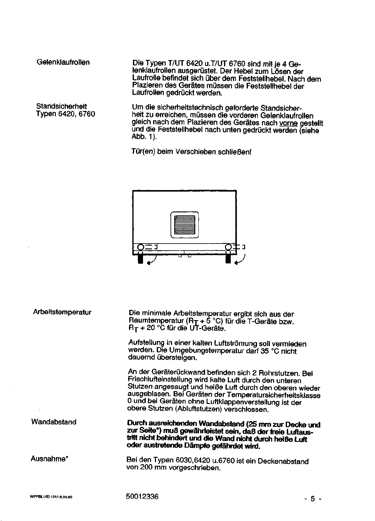
Standsicherheit
Typen 6420, 6760
Urn die sicherheitstechnisch geforderte Standsicher-
heit zu erreichen, mussen die vorderen Gelenklaufrollen
gleich nach dem Plazieren des Gerates nach vorne gestellt
und die Feststellhebel nach unten gedruckt werden (siehe
Abb.
v
1).
Tur(en) beim Verschieben schlieBen!
Arbeitstemperatur
Wandabstand
Ausnahme*
Die minimale Arbeitstemperatur ergibt sich aus der
Raumtemperatur (RT+ 5 °C) fur die T-Gerate bzw.
RT + 20 °C fur die UT-Gerate.
Aufstellung in einer kalten Luftstrdmung soil vermieden
werden.
Die Umgebungstemperatur darf 35 °C nicht
dauernd ubersteigen.
An der Gerateruckwand befinden sich 2 Rohrstutzen. Bei
Frischlufteinstellung wird kalte Luft durch den unteren
Stutzen angesaugt und heiBe Luft durch den oberen wieder
ausgeblasen. Bei Geraten der Temperatursicherheitsklasse
0 und bei Geraten ohne Luftklappenverstellung ist der
obere Stutzen (Abluftstutzen) verschlossen.
Durch ausreichenden Wandabstand (25 mm zur Decke und
zur Serte*) muB gewahrieistet sein, daB der freie Luftaustritt nicht behindert und die Wand nicht durch heiBe Luft
oder austretende Dampfe gefahrdet wird.
Bei den Typen 6030,6420 u.6760 ist ein Deckenabstand
von 200 mm vorgeschrieben.
WPPBL1/ID 101/18.04.90
50012336
Page 6
Zuluftleitung
Zur Frischluftversorgung des Gerates kann eine Zuluftleitung angeschlossen werden. Sie soil so ausgelegt
sein,
daB der gewunschte Luftwechsel erreicht
wird.
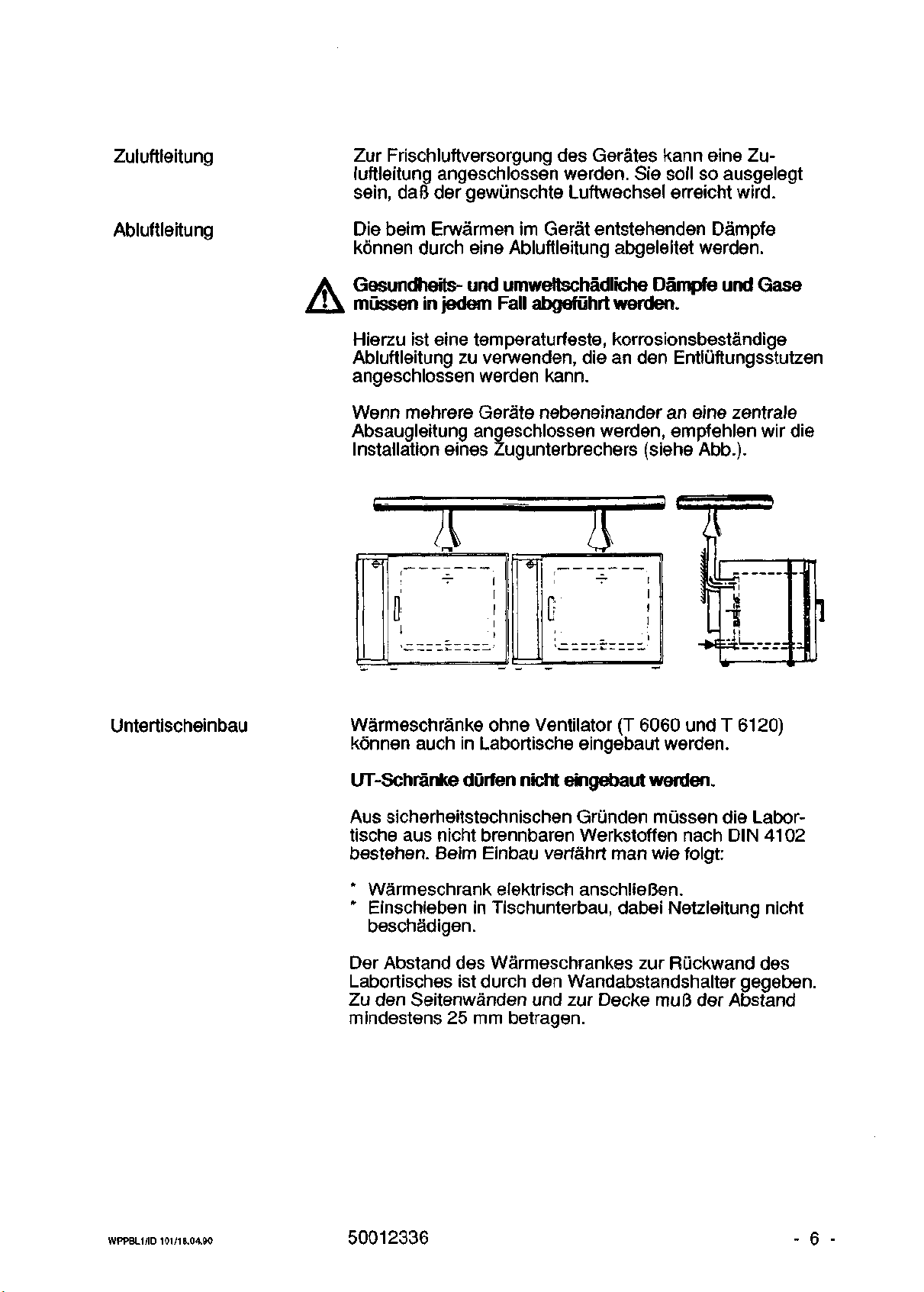
Abluftleitung
Die beim Erwarmen im Gerat entstehenden Dampfe
konnen durch eine Abluftleitung abgeleitet werden.
Gesundheits- und umweftschadliche Dampfe und Gase
mussen in jedem Fall abgefOhrt werden.
Hierzu ist eine temperaturfeste, korrosionsbestandige
Abluftleitung zu verwenden, die an den Entlijftungsstutzen
angeschlossen werden kann.
Wenn mehrere Gerate nebeneinander an eine zentrale
Absaugleitung angeschlossen werden, empfehlen wir die
Installation eines Zugunterbrechers (siehe Abb.).
•e-
J
("
' •
! ~ 1
( !
' _ i
•—_ _ A- —
i
0
i
Untertischeinbau
Warmeschranke ohne Ventilator (T 6060 und T 6120)
konnen auch in Labortische eingebaut werden.
UT-Schranke durfen nicht eingebaut werden.
Aus sicherheitstechnischen Grunden mussen die Labortische aus nicht brennbaren Werkstoffen nach DIN 4102
bestehen.
Beim Einbau verfahrt man wie folgt:
* Warmeschrank elektrisch anschlieBen.
* Einschieben in Tischunterbau, dabei Netzleitung nicht
beschadigen.
Der Abstand des Warmeschrankes zur Ruckwand des
Labortisches ist durch den Wandabstandshalter gegeben.
Zu den Seitenwanden und zur Decke muB der Abstand
mindestens 25 mm betragen.
WPPBL1 /ID 101/1 B.CH80
50012336
- 6 -
Page 7
Stapelung
Zubehor erforderlich !
6060
BaugroBe:
Bestell-Nr.:
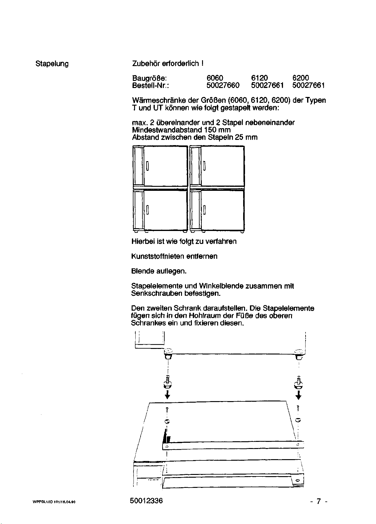
Warmeschranke der Groflen (6060, 6120, 6200) der Typen
T und UT konnen wie folgt gestapelt werden:
max. 2 ubereinander und 2 Stapel nebeneinander
Mindestwandabstand 150 mm
Abstand zwischen den Stapeln 25 mm
6120
50027660 50027661 50027661
6200
D
I
Hierbei ist wie folgt zu verfahren
Kunststoffnieten entfernen
Blende auflegen.
Stapelelemente und Winkelblende zusammen mit
Senkschrauben befestigen.
Den zweiten Schrank daraufstellen. Die Stapelelemente
fugen sich in den Hohlraum der FuBe des oberen
Schrankes ein und fixieren diesen.
0
I
WPPBL1/ID101/1B.0490 50012336
- 7 -
Page 8
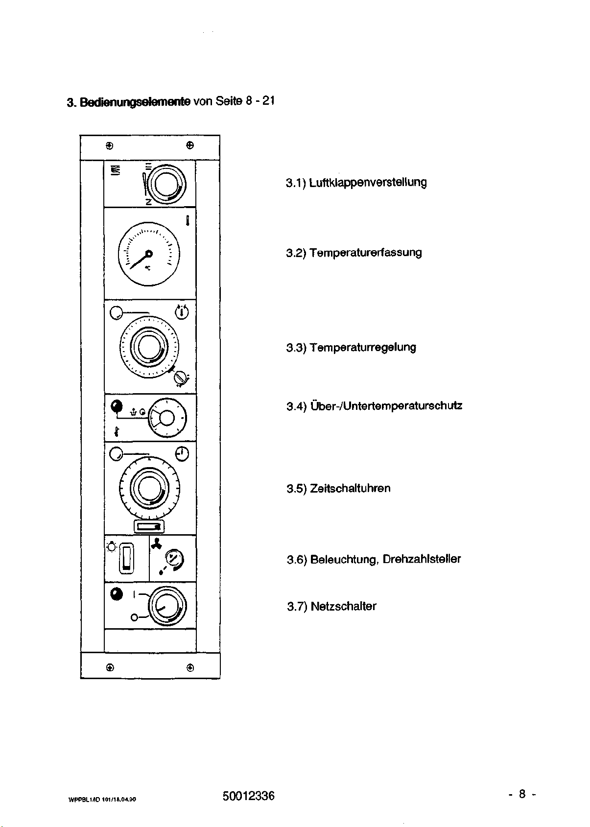
3. Bedienungseiemente von Seite 8-21
©
©
3.1) Luftklappenverstellung
3.2) Temperaturerfassung
©
3.3) Temperaturregelung
3.4) UberVUntertemperaturschutz
®
3.5) Zeitschaltuhren
3.6) Beleuchtung, Drehzahlsteller
3.7) Netzschalter
o
®
WPPBL1/ID 101/18.04.90
50012336
- 8 -
Page 9

3. Bedienetemente
3.1 Luftklappenverstellung
3.2 Temperaturerfassung
Temperaturanzeige
nur BaugroBen
6030 - 6200
Temperaturschreiber
auf
zu
Zeigerthermometer
40 °C bis 300 °C
Kreisblatt-
Temperaturschreiber
MeBbereich:
0 bis 300°C
Der Kreisblattschreiber benotigt zur Registrierung weder
Tinte noch Farbband. Die Aufzeichnung der Kurve erfolgt
durch periodisches Andrucken des spitzen Zeigers gegen
die druckempfindliche Diagrammscheibe. Dieses Schreibsystem ist, abgesehen vom Ersetzen der Diagramm-
scheibe, absolut wartungsfrei.
Die Diagrammscheiben werden mit einer Teilung
0 - 300 *C geliefert. Bei Nachbestellungen von Diagrammscheiben muB die Artikel-Nummer angegeben
werden.
Eur_5Q_Hz:
Diagrammscheibe Laufzeit 1 Tag Art.-Nr. : 50028271
Djagrammscheibe Laufzeit 7 Tage Art.-Nr. : 50028272
Diagrammscheibe Laufzeit 30 Tage Art.-Nr. : 50028273
EOLgOJHz:
Diagrammscheibe Laufzeit 20 h Art.-Nr. : 50029584
Diagrammscheibe Laufzeit 140 h Art.-Nr. : 50029585
Diagrammscheibe Laufzeit 25 Tage Art.-Nr.: 50029586
Mindestbestellmenge: 1 Satz (100 Scheiben)
Auswechseln der Diagrammscheibe:
Der Plexiglasdeckel wird durch eine leichte Drehung im
Gegenuhrzeigersinn abgenommen. Nach Entfernen der
Diagrammscheibe werden folgende Bedienungselemente
sichtbar:
WPPBL1/ID 101/18.04.90
Schlagstarke-Einstellung (Stroke):
Regulierschraube zur Einstellung der Schlagstarke;
Drehung im Uhrzeigersinn ergibt groBere Schlagstarke.
50012336
- 9 -
Page 10
Vorschubwahl
Mit diesem Schieber wird der gewunschte Vorschub
eingestellt.
-1 Tag / 7 Tage / 30 Tage (bei 50 Hz Netzfrequenz)
- 20 h / 5,8 Tage / 25 Tage (bei 60 Hz Netzfrequenz)
Die Zeigerspitze ist im schmalen Schlitz unterhalb der
Schlagstarken-Regulierschraube sichtbar. Sie kommt alle
6 Sekunden hervor, um den MeBpunkt zu registrieren. Je
nach Zeitpunkt der Abschaltung des Netzes kann der
Zeiger auch in Schreibstellung stehen bleiben.
Um Beschadigung des Zeigers, falls dieser in Schreib-
stellung steht, zu vermeiden, sollte der Plexiglasdeckel
nicht ohne eingesetzte Diagrammscheibe geschlossen
wercion.
Nachdem der gewunschte Vorschub eingestellt ist, wird die
neue Diagrammscheibe eingesetzt und auf die vier
Fuhrungsstifte im Zentrum gedruckt. Durch Drehen der
Antriebsachse im Uhrzeigersinn wird die Zeit am Umfang
der Diagrammscheibe auf die weiBe Marke am Instrumentenrand eingestellt. Mit einer leichten Drehung im
Uhrzeigersinn wird nun der Plexiglasdeckel eingerastet.
(Auf Aufschrift "ELMES 12" im Zentrum achten).
WPPBL1/ID
101/1
S.04.90
50012336 - 10 -
Page 11
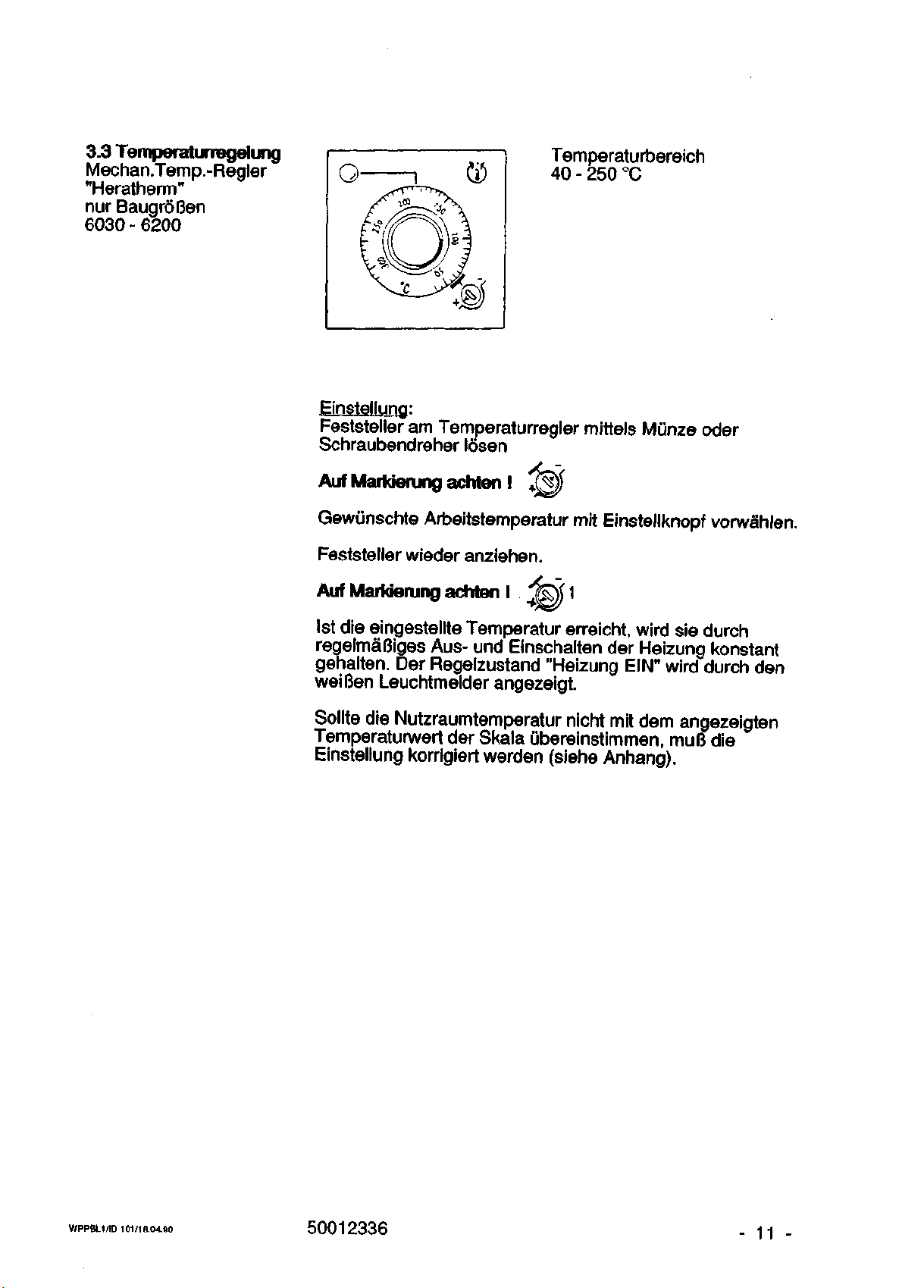
3.3 Temperatumegeiung
Mechan.Temp.-Regler
"Heratherm"
nur BaugroBen
6030 - 6200
Temperaturbereich
40 - 250 °C
Einstellung:
Feststeller am Temperaturregler mittels Miinze oder
Schraubendreher Ibsen
Auf Markierung achten I
Gewunschte Arbeitstemperatur mit Einstellknopf vorwahlen.
Feststeller wieder anziehen.
Auf Markierung achten 1
1st die eingestelite Temperatur erreicht, wird sie durch
regelmaGiges Aus- und Einschalten der Heizung konstant
genalten.
Der Regelzustand "Heizung EIN" wird durch den
weiBen Leuchtmelder angezeigt.
Sollte die Nutzraumtemperatur nicht mit dem angezeigten
Temperaturwert der Skala ubereinstimmen, muB die
Einstellung korrigiert werden (siehe Anhang).
WPPBL1 /ID 101/18.04.80
50012336
- 11 -
Page 12
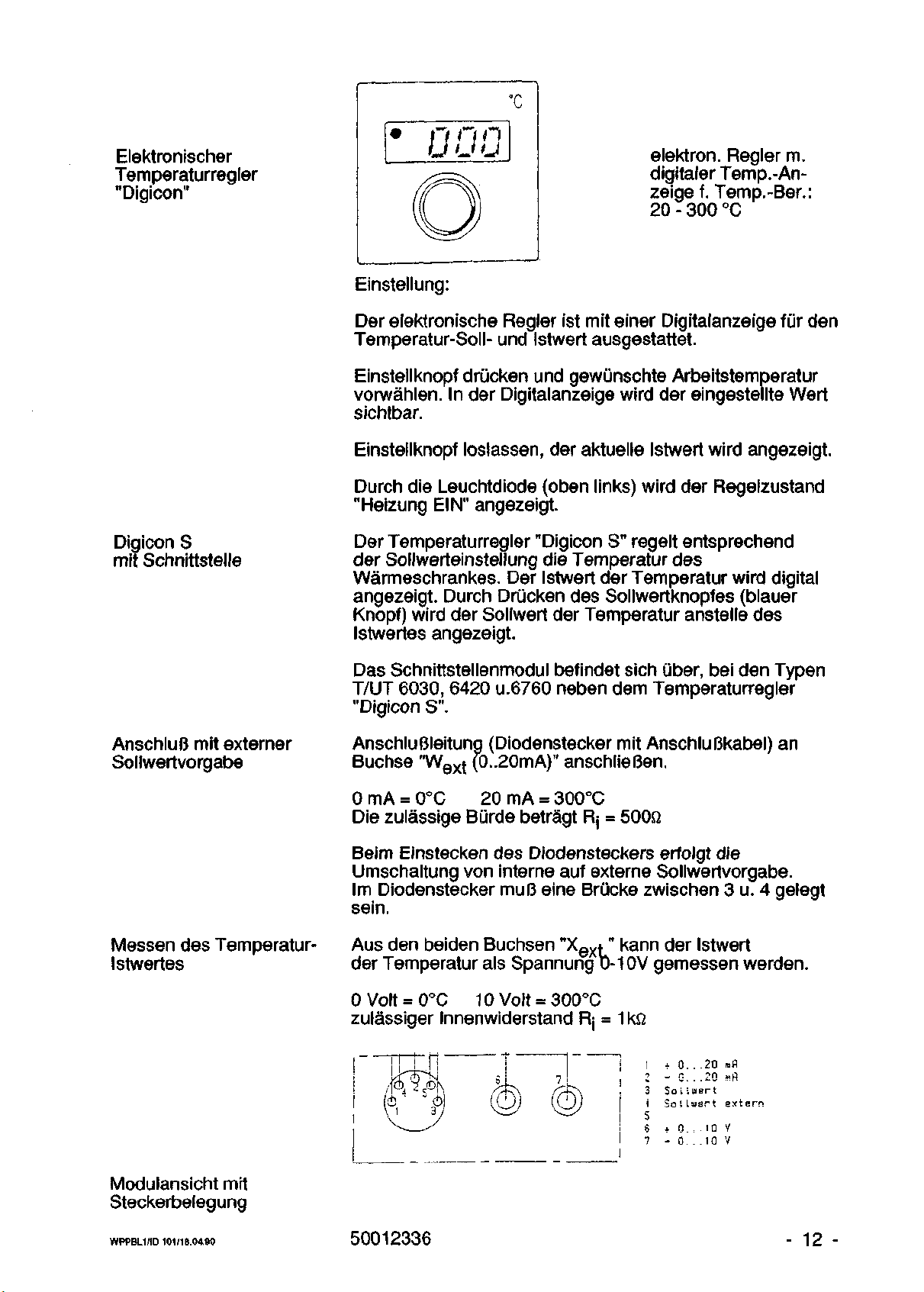
Elektronischer
Temperaturregler
"Digicon"
°c
• n n n
uuu
elektron.
digitaler Temp.-An
zeige f. Temp.-Ber
20 - 300 °C
Regler m
O
Einstellung:
Der elektronische Regler ist mit einer Digitalanzeige fur den
Temperatur-Soll- und Istwert ausgestattet.
Einstellknopf driicken und gewunschte Arbeitstemperatur
vorwahlen.
sichtbar.
Einstellknopf loslassen, der aktuelle Istwert wird angezeigt.
Durch die Leuchtdiode (oben links) wird der Regelzustand
"Heizung EIN" angezeigt.
In der Digitalanzeige wird der eingestellte Wert
Digicon S
mit Schnittstelle
AnschluB mit externer
Sollwertvorgabe
Messen des TemperaturIstwertes
Der Temperaturregler "Digicon S" regelt entsprechend
der Sollwerteinstellung die Temperatur des
Warmeschrankes. Der Istwert der Temperatur wird digital
angezeigt. Durch Driicken des Sollwertknopfes (blauer
Knopf) wird der Sollwert der Temperatur anstelle des
Istwertes angezeigt.
Das Schnittstellenmodul befindet sich iiber, bei den Typen
T/UT 6030, 6420 u.6760 neben dem Temperaturregler
"Digicon S".
AnschluBleitung (Diodenstecker mit AnschluBkabel) an
Buchse "Wex{ (0..20mA)" anschlieBen.
0 mA . 0°C 20 mA = 300°C
Die zulassige Biirde betragt Rj = 500Q
Beim Einstecken des Diodensteckers erfolgt die
Umschaltung von interne auf externe Sollwertvorgabe.
Im Diodenstecker muf3 eine Briicke zwischen 3 u. 4 gelegt
sein.
Aus den beiden Buchsen "Xext" kann der Istwert
der Temperatur als Spannung 0-10V gemessen werden.
Modulansicht mit
Steckerbelegung
WPPBL1
/ID 101/18.04.90
0Volt«0°C 10Volt = 300°C
zulassiger Innenwiderstand Rj = 1 kfi
+ 0. . .20 mfl
- 0 ... 20 ».fl
So i
liaart
Sa
1 Isjsrt
sx
tarn
* 0 - 10 V
- 0 ... 10 V
50012336 - 12 -
Page 13
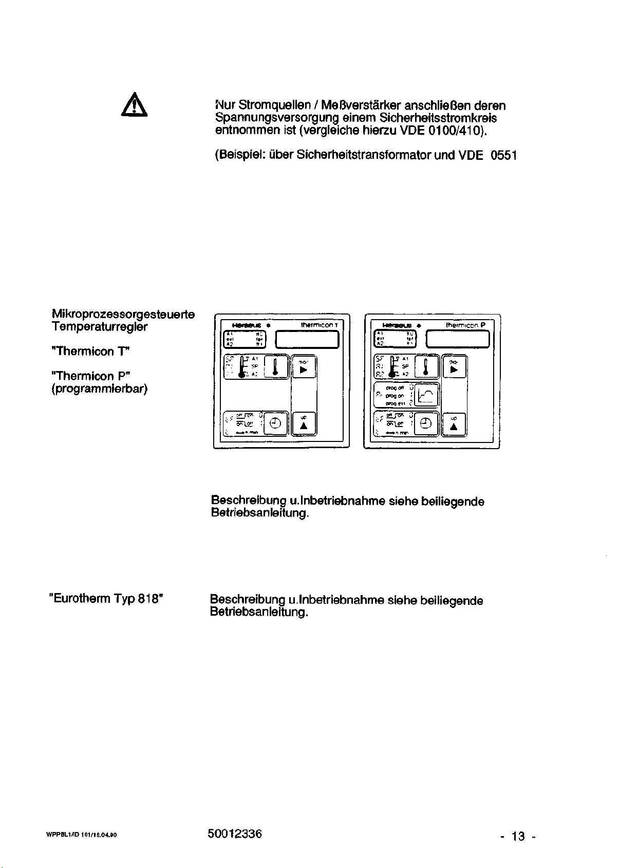
Nur Stromquellen / MeBverstarker anschlieBen deren
Spannungsversorgung einem Sicherheitsstromkreis
entnommen ist (vergleiche hierzu VDE 0100/410).
Mikroprozessorgesteuerte
Temperaturregler
"Therm icon T"
"Thermicon P"
(programmierbar)
(Beispiel:
Heraeus • thermicon T
[A.
rtc
1 eit la«
1«? lit
Giber Sicherheitstransformator und VDE 0551
1 1
Jj
>' *—•> H Tin
©
iieiaoLB
I A i n u
1 (>i tail
l»? «'
SF
fp*i
•
A
R:
JfsP
R.? #^> *?
prog o« u
'°--
prog on I
proq e«) .?
T
•
o
Ihermicon P
i
•
A
"EurothermTyp818"
Beschreibung u.lnbetriebnahme siehe beiliegende
Betriebsanleitung.
Beschreibung u.lnbetriebnahme siehe beiliegende
Betriebsanleitung.
WPPBL1/ID 101/18.04.90
50012336
- 13 -
Page 14
3.4 Uber-/Untertemperaturschutz
Die erforderlichen MaBnahmen zur thermischen Sicherhert sind in DIN 12880 Teil 1, Tabelle 3 (siehe Anhang)
festgelegt.
Die fur diese Warmeschranke zutreffende Temperatursicherheitsklasse ist auf dem Typenschikj angegeben.
Kein Ubertemperatur-
schutz
Temperatursicherheitsklasse 0:
Keinen direkten Schutz fur den Warmeschrank, dessen
Umgebung und Beschickungsgut.
Nurfur ungefahrliches Beschickungsgut zulassig (siehe
auch Labomchtlinien ZH 1/119).
- Der beim Versagen des Temperatur-Regelsystems
entstehende Anstieg der Innenraumtemperatur
fuhrt zu Uberhitzungsschaden.
- Nur fiir Ciberwachten Betrieb zulassig.
- Der Betrieb dieser Warmeschranke mu3 in hinreichend kurzen Abstanden kontrolliert werden.
- Warmeschranke dieser Temperatur-Sicherheitsklasse
durfen nicht eingebaut Oder gestapelt werden.
Nachrustungen der Warmeschranke der Schutzklasse 0
sind moglich, wenn ein Temperatur-Wahlbegrenzer,
Temperatur-Wahlwachter oder ein Temperatur-Wahlwachter gegen Uber- und Unterschreitung der Temperatur
installiert
wird.
WPPBL1/ID 10V18.04.90
Die Nachrustung kann jederzeit durch den Service der
Firma Heraeus erfolgen.
50012336
- 14 -
Page 15
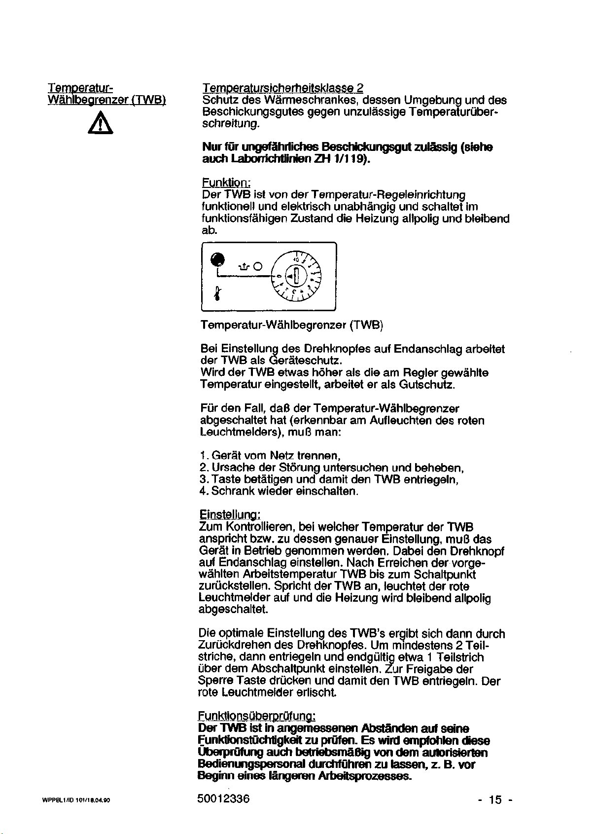
Temperatur-
Wahlbegrenzer (TWB)
Temperatursicherheitsklasse 2
Schutz des Warmeschrankes, dessen Umgebung und des
Beschickungsgutes gegen unzulassige Temperaturuber-
schreitung.
Nurfur ungefahriiches Beschickungsgut zulassig (siehe
auch Labonichtlinien ZH 1/119).
EunMQn:
Der TWB ist von der Temperatur-Regeleinrichtung
funktionell und elektrisch unabhangig und schaltet im
funktionsfahigen Zustand die Heizung allpolig und bleibend
ab.
Temperatur-Wahlbegrenzer (TWB)
Bei Einstellung des Drehknopfes auf Endanschlag arbeitet
der TWB als Gerateschutz.
Wird der TWB etwas hoher als die am Regler gewahlte
Temperatur eingestellt, arbeitet er als Gutschutz.
Fur den
Fall,
daB der Temperatur-Wahlbegrenzer
abgeschaltet hat (erkennbar am Aufleuchten des roten
Leuchtmelders), muB man:
1.
Gerat vom Netz trennen,
2.
Ursache der Storung untersuchen und beheben,
3. Taste betatigen und damit den TWB entriegeln,
4.
Schrank wieder einschalten.
Einstellung:
Zum Kontrollieren, bei welcher Temperatur der TWB
anspricht bzw. zu dessen genauer Einstellung, muB das
Gerat in Betrieb genommen werden. Dabei den Drehknopf
auf Endanschlag einstellen. Nach Erreichen der vorgewahlten Arbeitstemperatur TWB bis zum Schaltpunkt
zuriickstellen. Spricht der TWB an, leuchtet der rote
Leuchtmelder auf und die Heizung wird bleibend allpolig
abgeschaltet.
Die optimale Einstellung des TWB's ergibt sich dann durch
Zuruckdrehen des Drehknopfes. Urn mindestens 2
Teilstriche, dann entriegeln und endgult|g etwa 1 Teilstrich
uber dem Abschaltpunkt einstellen. Zur Freigabe der
Sperre Taste drucken und damit den TWB entriegeln. Der
rote Leuchtmelder erlischt.
WPPBL1/ID 101/18.04.90
Funktionsuberprufung:
Der TWB ist in angemessenen Abstanden auf seine
Funklionstuchtigkeit zu prufen. Es wird empfohlen diese
Uberprufung auch betriebsmaBig von dem autorisierten
Bedienungspersonal durchfuhren zu lassen, z. B. vor
Beginn eines langeren Arbeitsprozesses.
50012336
- 15 -
Page 16
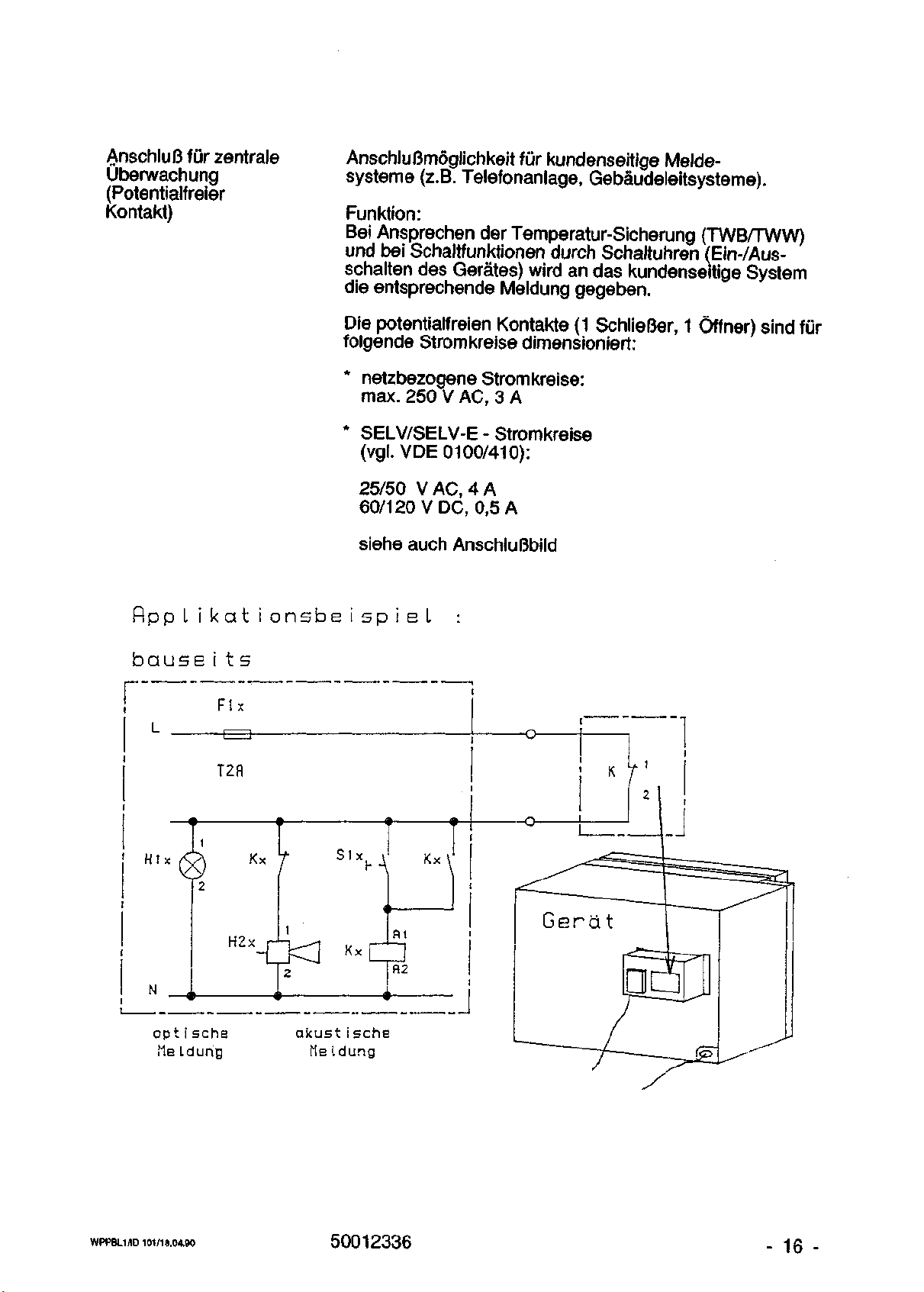
AnschluB fur zentrale
Uberwachung
(Potentialfreier
Kontakt)
AnschluBmoglichkeit fur kundenseitige Meldesysteme (z.B. Telefonanlage, Gebaudeleitsysteme).
Funktion:
Bei Ansprechen der Temperatur-Sicherung (TWB/TWW)
und bei Schaltfunktionen durch Schaltuhren (Ein-/Ausschalten des Gerates) wird an das kundenseitige System
die entsprechende Meldung gegeben.
Die potentialfreien Kontakte (1 SchlieBer, 1 Offner) sind fur
folgende Stromkreise dimensioniert:
* netzbezogene Stromkreise:
max. 250 V AC, 3 A
* SELV/SELV-E - Stromkreise
(vgl.VDE 0100/410):
25/50 V AC, 4 A
60/120 V DC, 0,5 A
siehe auch AnschluGbild
flppLikationsbeispieL
bause i t
s
:
r
opt i sche
Me Ldung
akust i sche
fie ldung
WPPBL1/ID 101/18.04.90
50012336
- 16 -
Page 17
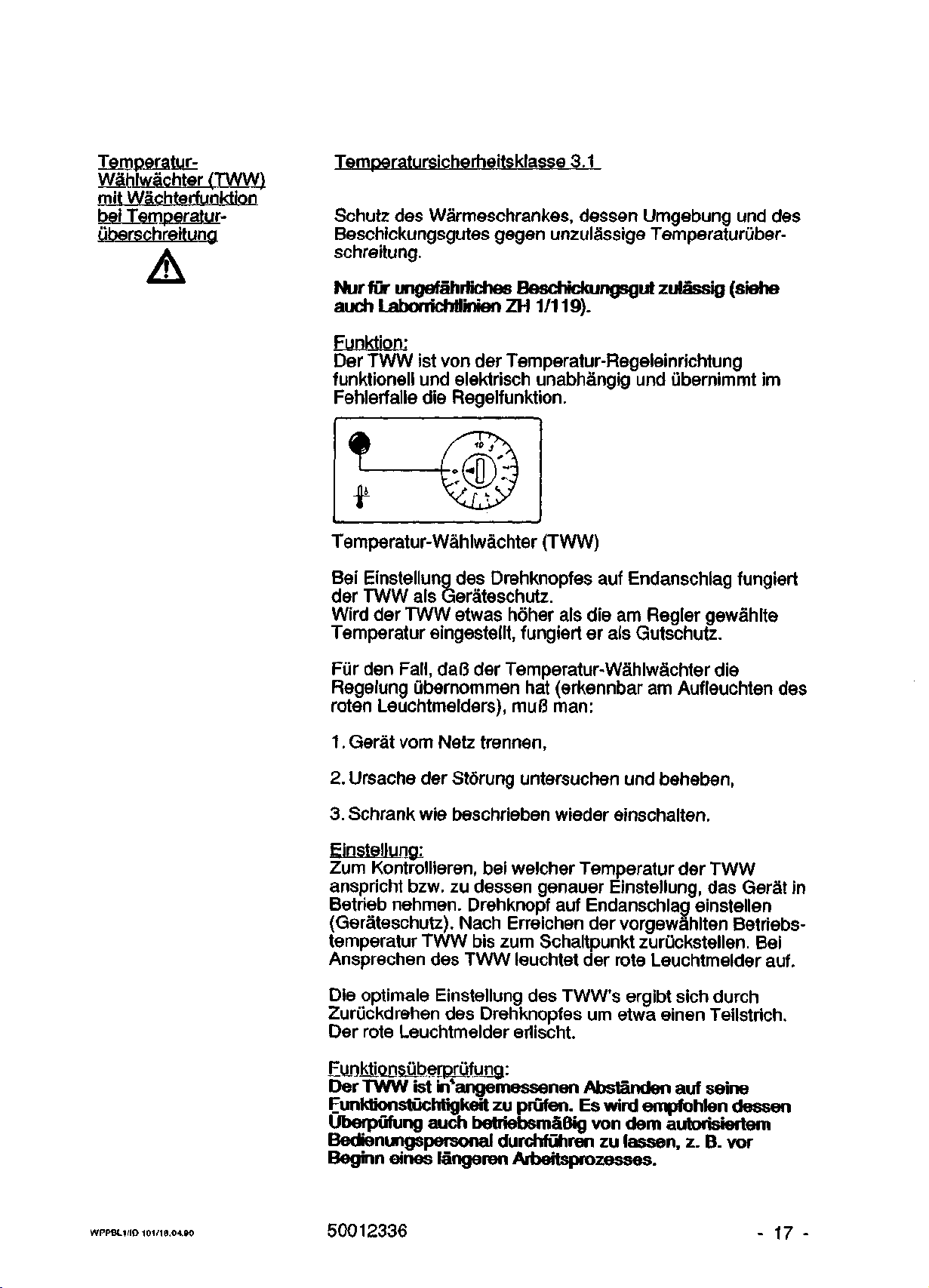
TemperaturWahlwachter (TVyW)
mit Wachterfunktion
bei TemperaturGberschreitung
Temperatursicherheitsklasse 3.1
Schutz des Warmeschrankes, dessen Umgebung und des
Beschickungsgutes gegen unzulassige Temperaturuberschreitung.
Nur fur ungefahriicnes Beschickungsgul zulassig (siehe
auch Labomchtlinien ZH 1/119).
Funktion:
Der TWW ist von der Temperatur-Regeleinrichtung
funktionell und elektrisch unabhangig und ubernimrnt im
Fehlerfalle die Regelfunktion.
Temperatur-Wahlwachter (TWW)
Bei Einstellung des Drehknopfes auf Endanschlag fungiert
der TWW als Gerateschutz.
Wird der TWW etwas hoher als die am Regler gewahlte
Temperatur eingestellt, fungiert er als Gutschutz.
Fur den
Fall,
da(3 der Temperatur-Wahlwachter die
Regelung ubernommen hat (erkennbar am Aufleuchten des
roten Leuchtmelders), muB man:
1.
Gerat vom Netz trennen,
2.
Ursache der Storung untersuchen und beheben,
3. Schrank wie beschrieben wieder einschalten.
Einstellung:
Zum Kontrollieren, bei welcher Temperatur der TWW
anspricht bzw. zu dessen genauer Einstellung, das Gerat in
Betrieb nehmen. Drehknopf auf Endanschlag einstellen
(Gerateschutz). Nach Erreichen der vorgewahlten Betriebstemperatur TWW bis zum Schaltpunkt zuruckstellen. Bei
Ansprechen des TWW leuchtet der rote Leuchtmelder auf.
Die optimale Einstellung des TWW's ergibt sich durch
Zuruckdrehen des Drehknopfes urn etwa einen Teilstrich.
Der rote Leuchtmelder erlischt.
Funktionsuberprufung:
Der TWW ist in*angemessenen Abstanden auf seine
Funktionstuchtigkett zu prufen. Es wird empfohlen dessen
UberpOfung auch betriebsmaBig von dem autorisiertem
Bedienungspersonal durchfuhren zu lassen, z. B. vor
Beginn eines langeren Arbeitsprozesses.
WPPBL1/ID 101/18.04.90
50012336
- 17 -
Page 18

Temperatur-
Wahlwachter TWW U/U
WaGhterfunktion
bei Temperaturiiberund Unterschreitung
Temperatur-Sicherheitsklasse 3.3
Schutz des Warmeschrankes, dessen Umgebung und des
Beschickungsgutes gegen unzulassige Temperaturuber-
und -unterschreitung.
Nur fur ungefahrtiches Beschickungsgut zulassig (siehe
auch Laborrichtlinsen ZH
1/119).
Funktion;
Erganzend zur Funktion des TWW's nach Temperatur-
sicherheitsklasse 3.1 bietet dieser Wachter, wahlweise
uber Kippschalter zu- und abschaltbar, einen zusatzlichen
Schutz gegen Ternperaturunterschreitung des
Beschickungsgutes bei Ausfall des Reglers.
Untertemperaturschutz Ubertemperaturschutz
Temperatur-Wahlwachter mit Uber- und Untertemperaturschutz (TWW U/U).
Einstellung des Ubertemperaturschutzes:
Die Einstellung der gewunschten Ubernahmetemperatur
bei Temperaturuberschreitung wie unter'TWW"
beschrieben vornehmen.
Einstellung des Untertemperaturschutzes:
Nach Erreichen der Solltemperatur weiBen Schalter
einschalten.
Leuchtmelder im Schalter leuchtet auf.
Der Schaltpunkt wird auf der Skala des TWW/U's durch
langsames Drehen ermittelt (erkennbar am Aufleuchten
des orangefarbenen Leuchtmelders).
Danach den Drehknopf etwas zuruckdrehen, so daB
orangefarbener Leuchtmelder erlischt.
FunktionsOberprQfung:
Der TWW U/U ist in angemessenen Abstanden auf seine
Funktionstuchtigkeit zu prufen. Es wird empfohlen dessen
Uberpufung auch betriebsmaBig von dem autorisierten
Bedienungspersonai durchfuhren zu lassen, z. B. vor
Beginn eines langeren Arbeitsprozesses.
WPPBL1/ID 101/18.04.90
50012336
- 18 -
Page 19
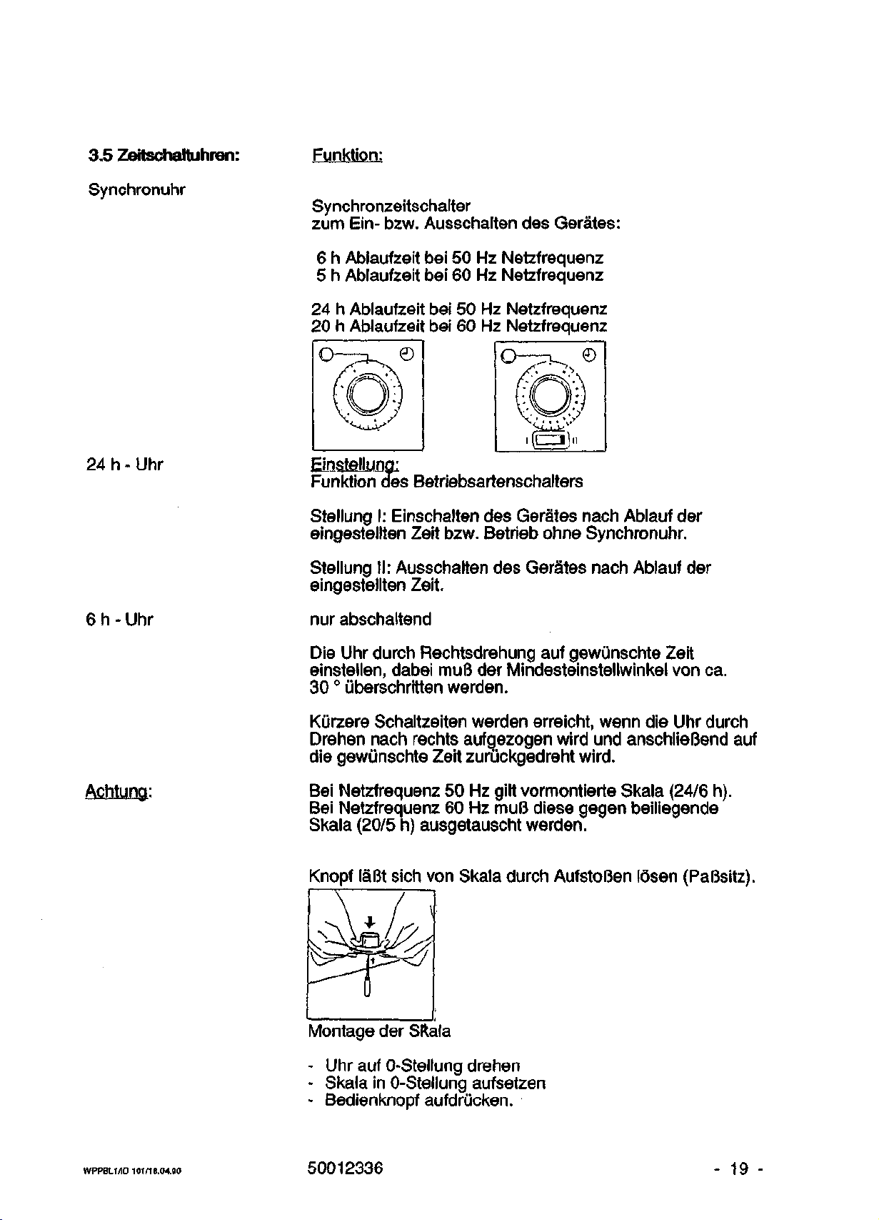
3.5 Zeitschaltuhren:
Synchronuhr
Funktion:
Synchronzeitschalter
zum Ein- bzw. Ausschalten des Gerates:
6 h Ablaufzeit bei 50 Hz Netzfrequenz
5 h Ablaufzeit bei 60 Hz Netzfrequenz
24 h Ablaufzeit bei 50 Hz Netzfrequenz
20 h Ablaufzeit bei 60 Hz Netzfrequenz
24 h - Uhr
6 h - Uhr
Achtung:
Einstellung:
Funktion des Betriebsartenschalters
Stellung I: Einschalten des Gerates nach Ablauf der
eingestellten Zeit bzw. Betrieb ohne Synchronuhr.
Stellung II: Ausschalten des Gerates nach Ablauf der
eingestellten Zeit.
nur abschaltend
Die Uhr durch Rechtsdrehung auf gewunschte Zeit
einstellen,
dabei muB der Mindesteinstellwinkel von ca.
30 ° iiberschritten werden.
Kiirzere Schaltzeiten werden erreicht, wenn die Uhr durch
Drehen nach rechts aufgezogen wird und anschlieBend auf
die gewunschte Zeit zuruckgedreht
wird.
Bei Netzfrequenz 50 Hz gilt vormontierte Skala (24/6 h).
Bei Netzfrequenz 60 Hz muB diese gegen beiliegende
Skala (20/5 h) ausgetauscht werden.
Knopf laBt sich von Skala durch AufstoBen losen (PaBsitz).
WPPBL1/ID 101/1B.04.90
Montage der SRala
- Uhr auf 0-Stellung drehen
- Skala in 0-Stellung aufsetzen
- Bedienknopf aufdrucken.
50012336
- 19 -
Page 20

Tagesprogram m uhr
Funktion:
Zum Ein- bzw.Ausschalten des Gerates.
ELnsiellujng:
Bei Betriebsbeginn aktuelle Tageszeit auf der
Programmscheibe durch Rechtsdrehung einstellen.
Gewunschte Schaltzeitpunkte durch Rasten der Reiter
wahlen.
Gerastete Rotsegmente der Skala zeigen die Einschaltzeit
an.
Minimale Schaltfrequenz 15 Minuten.
Wochenprogammuhr
Funktion:
Zum Ein- bzw.Ausschalten des Gerates.
Aktuelle Tageszeit und Wochentag auf Programmscheibe
durch Rechtsdrehung einstellen.
1 = Mo., 2 - Di., 3 = Mi., 4 « Do.,
5 = Fr., 6 = Sa., 7 = So.
Gewunschte Schaltzeit durch Rasten der Reiter wahlen.
Minimale Schaltfrequenz 2 Stunden.
Betriebsartenumschalter:
= Automatikbetrieb des Gerates mit Uhrfunktion
= Handbetrieb: Uhrfunktion auBer Betrieb.
Digitale Wochen-
Siehe separate Bedienungsanleitung.
Programmuhr
WPPBL1/ID 101/18.04.90 50012336 - 20 -
Page 21
3.6 Schatterfcombination
Innenraumbeleuchtung
mit Tiirfenster
Drehzahlverstellung
Umluftmotor oder
Frischluftgeblase
Achtung!
Oberflache Verbrennungsgefahr!
Oberhalb des Turfensters besteht durch heiBe
•©-
1min/
9min
Taste fur Innenraumbeleuchtung
Kein Dauerbetrieb zulassig!
Hochsteinschaltzeit betragt 1 Minute, danach 9 Minuten
Mindestabkuhlzeitl
E
3.7 Netzschatter:
Stufenlos einstellbar von min. bis max. Drehzahl.
Funktion auch abschaltbar (bei den Typen
UT 6420 UT 6760 und Ausfuhrungen mit Frischluftgeblase
ist diese Funktion aus Sicherheitsgriinden nicht
abschaltbar).
Funktion:
Allpoliges Ein- bzw. Ausschalten des Gerates durch
Drehen des Knopfes.
Netzschalter einschalten,
WPPBL1 /ID
101
/18.04.90
der grune Leuchtmelder leuchtet auf.
50012336
- 21 -
Page 22

4. Inbetriebnahme
Einlagen u.
Auflagebugel
Die Einlagen und ihre Auflagebugel sind bei Anlieferung im Innenraum des Schrankes befestigt. Die Transportbefestigungen mussen vor Inbetriebnahme entfernt
werden.
Die Auflagebugel konnen in beliebige Locher der Lochreihen eingehangt werden. Die Einlagen werden so auf die
Auflagebugel geschoben, daB die gabelformige Kippsicherung den Bugel untergreift.
Der Nutzraum ist der Teil des Innenraumes, der von den
Wandungen allsertig einen Abstand von 1/10 des jeweiligen
Innenraumes hat (siehe auch DIN 12 880 Teil 2).
Hinweis fur die
Beschickung
Nur dieser Teil des Innenraumes sollte beschickt werden.
Das Beschickungsgut ist auf den Einlagen nicht zu
dicht anzuordnen (nur 70% der Flache beschicken), damit
die Luftzirkulation nicht gestort wird und eine gleichmaBige
Erwarmung gewahrleistet ist.
Nutzraumboden darf nicht beschickt werden!
Tur schlieBen
Netzschalter einschalten
- gainer Leuchtmelder leuchtet auf
Temperaturregler auf die gewiinschte Arbeitstemperatur
einstellen
Nach dem Erreichen der Solltemperatur den
Temperaturschutz einstellen.
"HeiBe Turoberflache"
- im Bereich der Tiirfenster
- im Bereich der mittleren Turkante
(nur bei Typ 6760)
WPPBL1/ID 101/18.04.90
50012336
- 22 -
Page 23

5. Wartung und
Instandsetzung
In angemessenen Zeitabstanden ist das Gerat auf
seine FunktionstiJchtigkeit zu prufen. Insbesondere gilt dies
fur den Temperatur-Wahlbegrenzer/Wachter.
Die Erhaltung der Normgerechtheit und Sicherheit des
Geraies ist nur dann gewahrfeistet, wenn die Wartungsvon autorislertem Personal vorgenommen werden.
und Instandsetzungsarberten bzw. Nachaistungen
Vor Wartungs- oder Instandsetzungsarberten ist das
Gerat vom Netz zu trennen.
Nachstellen der Tur
1.
Verstellen des
SchlieBhakens
2.
Verstellen des
Turlagerbolzens
Wenn die Tur nicht mehr einwandfrei schlieBt, kann sie
durch Verstellen des Turlagerbolzens und der SchlieBhaken nachgestellt werden:
Mutter M6 des SchlieBhakens mit Schlussel (SW 10)
losen und SchlieBhaken im Uhrzeigersinn drehen,
mindestens eine ganze Umdrehung. Haken muB nach
einer Umdrehung wieder in der gleichen Position stehen.
Mutter M6 wieder anziehen.
Kreuzschlitzschraube des Turlagerbolzens losen.
Mit kleinem Dorn ein Mitdrehen des Turlagerbolzens
verhindern. Nach L6sen der Schraube, Turlagerbolzen
mittels Dorn verdrehen und gewunschte Einstellung in
Hohe und Tiefe ermitteln. Kreuzschlitzschraube wieder
anziehen und Tur auf Dichtigkeit prufen.
Dichtungswechsel
Herausnahme der
Inneneinbauten
WPPBL1/ID 101/18.04.90
Defekte Dichtung abziehen, neue Dichtung aufspannen.
Danach ist das Gerat auf jeden Fall auf seine Dichtheit zu
prufen.
Es ist darauf zu achten, dal3 die Klammern wieder
eingesetzt werden.
Fur den Ausbau der Inneneinbauten im Nutzraum ist ein
Kreuzschlitzschraubendreher zu verwenden.
- untenliegendes Bodenblech abschrauben
- an den Seiten stehende Luftleitbleche abschrauben
- *an der Ruckwand stehende Vorstellwand abschrauben
- die einzelnen Einbauten herausnehmen
*nur bei UT-Schranken
50012336
- 23 -
Page 24

Pflegehinweise
Innenbehalter:
Es sollten in geringen Mengen handelsubliche Reinigungsmittel verwendet werden, jedoch keine Sauren, keine
chlorhaltigen Losemittel oder Kochsalziosungen.
Bedienelemente (Module):
am besten nur mit einem feuchten Lappen abwischen.
Ersatzteile
Schaltplane
Bei Reklamationen oder Ersatzteilbestellungen bitte Daten
vom Typenschild angeben.
Sicherheit und Funktion sind nur durch original Heraeus
Ersatzteile gewahrleistet.
Eine Ersatzteilliste kann unter Angabe der
Typenbezeichnung und der Fabrikationsnummer des
Gerates bei unseren Servicestellen angefordert werden
(siehe Servicestellen-Verzeichnis).
BR
BR
BR
BR
6000
6000
6000
6000
220
110
380
220
V/1
~
V/1
~
V/3~
V/3~
50011620
50030370
50011621
50030371
WPPBL1 /ID 101/16.04.90
50012336
- 24 -
Page 25

Tabeile 3, aus DIN 12880
Sicherheitseinrichtungen gegen Funktionsstorungen im Temperaturregelkreis,
Klassifizierung von Warmeschranken nach DIN 12 880 Teil 1, Tabeile 3.
Die Klasse beschreibt Schutzgegenstande und Schutzumfang und die zu dessen
Erreichung erforderlichen SicherheitsmaBnahmen fur den einfachen Fehlerfall im
Temperaturregelkreis.
Klasse
0
1
2
3
3.1
3.2
Schutzziel
-
Schutz
Warme-
schrankes
Schutz
Warmeschrankes
der
gebung
des
schickungsgutes
des
des
Um-
und
Be-
Schutzumfang
-
Im
Fehlerfalle
geht
vom
Harmeschrank
keine Gefahr
aus
Im
Fehlerfall
geht weder
Warmeschrank
noch
vom Beschickungsgut
eine Gefahr
aus
Im
Fehlerfall
ist
das Beschickungsgut
gegen
Uberhit-
zung und/oder
Unterkiihlung
geschutzt
(z.B.
Brut-
schrank)
vom
S1cherhe1ts
einrichtung
nach Abschnitt
5,5
-
TB
Oder
TS
TWB
TWH
mit
Wach-
terfunktion
Temperaturiiber-
schreitung
Temperaturunterschreitung
bei
Si
cherheltsmaBnahmen
Nur
Uberwachter
trieb
*) mit
fahrlichem
kungsgut
zulassig,
Beschik-
Be-
unge-
oder Uberhitzung
durch konstruktive
MaBnahmen
ausge-
schiossen.
besondere
heitsmaBnahmen
Abhangigkeit
Sicher-
in
vom
Verwendungszweck
3.3
TemperaturUber-und
unter-
Schreitung
*)bei uberwachtem Betrieb mu3 der Betriebszustand des Warmeschrankes in hinreichend kurzen Abstanden kontrolliert werden.
WPPBL1/ID 101/18.04.90 50012336
- 25 -
Page 26

Technische Daten
Materialien:
Innenbehalter
Horden
TUrdichtung
Heizung
AuBengehause
*) Rost-
**) Verzinktes Stahit
Farben:
AuBengehause,grauws
Module,achatgrau
Bedienelemente
lichtblau
Abmessungen(mm)
siehe MaBskizze
AuBenroaBe:
*
Gehause
TA ink!. TUrgriff
B
A
H
A
InnenraummaBe:
Tj
B
H
I
Innenraumvol umend)
Gewichte
(kg)
Leergewicht
max.
max.
und
Beschickung
Hordeniast:
Flachenformig
Punktformig
6030
T
1.4301
St.verchromt
Si
1.Kautschuk
1.4435
**)
saurebestandiger Stahl
jiech-AuBenbesd
RAL 9002
RAL 7038
RAL
5012
S. 29
610
552
552
*)
*)
370
352
231
30
40
50
20
15
6060
T
UT
1.4301
St.
*)
verchromt
Sil.Kautschuk
14435
*)
lichtung
mit hr
RAL 9002
RAL 7038
RAL
5012
610
647
744
744
552
552
370
339
403
403
380
380
57
52
50
53
50
20
15
6120
T
UT
14301
*)
St.
verchromt
Sil.Kautschuk
14435
*)
:zefestem Polyei
RAL 9002
RAL 7038
RAL
5012
610
647
895
895
696
696
370
323
554
554
524
524
107
94
65
75
50
20
15
6200
T
UT
14301
*)
St.
verchromt
Sil.Kautschuk
14435
*)
terlack.
RAL 9002
RAL 7038
RAL
5012
790
827
895
895
816
816
550
503
554
554
644
644
196
180
92
100
75
40
20
6420
T
UT
14301
*)
St.
verchromt
Sil.Kautschuk
14435
*)
RAL 9002
RAL 7038
RAL
5012
790
744
1813
1838
550
522
544
544
1366
1319
409
375
153
163
75
40
20
6760
T
UT
14301
*)
St.
verchromt
Sil.Kautschuk
14435
*)
RAL 9002
RAL 7038
RAL
5012
790
1200
1813
1838
550
522
1000
1000
1366
1319
751
689
223
241
150
40
20
WPPBL1 /I D 101/18.04.90
50012336
- 26 -
Page 27

Technische Daten
T
6030
T
6060
UT
T
6120
UT
T
6200
UT
T
6420
UT
T
6760
UT
Elektrische
Nennspannung
Nennfrequenz
Nennstrom
Nennleistung
Zeiten:(Minuten)
Anheizzeit
klappe geschl.)
25
300
Erhoizeit
geoffnet)
auf
gangswertes
Luftwechsel
Luftkiappe offen
Daten:
°C auf:
°C
150
°C
70
°C
99 1 des
300
150
70
pro h
300
150
70
(A)
(Tur 1 min
°C
°C
°C
°C
°C
°C
(V)
(Hz)
(kW)
(Luft-
,
Aus-
bei:
von
50
220
/ 60
3,4
0,75
75
30
15
7
6
2
33
34
14
50
6,5
1,4
35
10
10
14
12
220
/ 60
6
1
6
4
4
7
,8
,49
55
20
10
33
35
36
220
50
/ 60
9,3
1
2,0
60
20
10
6
3
1
9
4
4
25
21
19
0,3
2,25
60
25
15
11
5
1
27
29
32
220
50
11,1
2,4
65
30
20
10
5
5
21
15
11
/ 60
1
2,2
2,65
75
23
7
10
2
2
28
41
47
50
6,5
3,6
70
35
40
18
11
21
16
11,5
380
/ 60
6
6,8
3,8
80
30
10
21
19
47
380
50
/ 60
8,2
5,4
80
55
55
6
6
1
8
5
3
12
14
10
8,6
5,6
85
30
12
11
6
1
12
18
10
WPPBL1/ID 101/18.04.90
50012336
- 27 -
Page 28

Technische Daten
Max.
Fri
schluf
tmengedir/h)
(Luftklappe offen)
300
°C
150
°C
70
°C
bei UT-Typen
max.
Ventilator-
lei stung
Umluftmenge
Temperaturen**:
(bei 25 °C)
Max.
Vent.-Leistg.
in nr/min
*l_eerverbrauch
Luftklappe geschl.
bei
300 °C
150
°C
70
°C
Nenntemperatur
raumliche Tempera-
turabweichungen
Luftklappe geschl.
300
°C
150
°C
70
°C
zeitliche Temperaturabweichungen
Nenntemperatur
Genauigk. Temp.-Anz.
Fernthermometer
in % v.Bereichsendw.
digitale Anzeige
in % v.Bereichsendw.
mit
(Hh/h)|
(°C)
bei
CO
T
3
,41
2
,86
2
,6
780
265
85
300
±
±
±
6
4
2
61
-
<
±
±
20
°(
0
3
1
3,68
3,96
4,36
6,5
1280
580
265
±
7
±
2,4
±
0,9
,5
UT
6030
T
1,4
1,45
0,6
-
415
150
55
300
°C
±
5,
3
0
±
2,
4
±
1,
5
<
o,
±
3
+
1
T
1 ,06
0,91
0,53
550
200
75
300
±
5
±
4
±
2
6060
-
°C
<
o,
±
3
±
1
UT
2,5
2,65
2,73
2,3
900
410
185
±
6
±
3
±
1
5
T
5
,04
3
,6
2
,64
1000
350
1
20
300
±
±
±
6200
-
°C
5,5
4
1,8
<
0
±
3
±
1
UT
6,7
9,8
11,27
4,1
1570
695
325
±
5,6
±
3,1
±1,3
5
T
10,3
7,8
5,6
1800
610
210
±
3,6
±
3,5
±
2,9
6420
-
300
<
0
±
3
±
1
UT
10,3
9,8
9,8
6,4
2500
1100
420
°C
±
3,6
±
2,9
±
0,8
5
T
10,3
12
2600
890
280
±
4,8
±
4,9
±
2,4
6760
8,6
-
300
<
±
±
0
3
1
UT
10,3
15,5
8,6
7
3300
1250
520
°C
±
4,4
±
3
±
1
5
entspricht Warmebelastung des Aufstellungsraumes
gemessen nach DIN 12 880 Teil 2.
WPPBL1/1D 101/18.04.90
50012336
-
28 -
Page 29

MaBskizzen
HA
LJ
BA
Baugio0efi6030, 6420.6760 Baug«5fien 6060.6120.6200
WPPBL1/ID 101/17.04.90
50012336
- 29 -
Page 30

Reglereinstellung
des mechanischen
Reglers "Heratherm"
Sollte die Temperatur im Nutzraum nicht mit dem auf
der Skala des mechanischen Reglers eingestellten
Wert ubereinstimmen kann die Skala neu eingestellt
werden.
Hierzu sind folgende Handgriffe notwendig:
1.
Blauen Knopf mit Skala abziehen
2.
Blauen Knopf aus Skala herausdrucken (Abb. unten)
3. Skala wieder auf Modul aufsetzen
4.
Temperaturwert mit Skalenwert vergleichen und neu
einstellen
5. Blauen Knopf wieder aufdrucken
WPPBL1/ID 101/17.04.90
50012336
- 30 -
Page 31

Eurotherm-Regler mit Schnittstelle RS 232
Belegung der 25-poligen D-Sub-Buchse:
13
00000600 6~6 0 0 0
oooo o[o oooooo
25 14
Alls nicht aufgefiihrten Pins sind unbeschaltet
Die Steckerbelegung der Schnittstelle ist so ausgefiihrt, da6 ein direkter AnschluB an
einen IBM oder IBM-kompatiblen Rechner moglich ist, wenn der Rechner mit einem
25-poligen Stecker ausgerustet ist. Besitzt die Rechnerschnittstelle einen 9-poligen
Stecker, ist ein handelsiiblicher Adapter (9-polige Buchse auf 25-poligen
Steckerjeinsetzbar.
Bei Auslieferung des Gerates ist die Regieradresse auf 00, die Baudrate auf 9600
eingestellt. Fur andere Adressen oder andere Baudraten muB der Regler umkonfiguriert
werden (siehe Bedienungsanleitung des EUROTHERM-Reglers).
1 Pin
1
2
3
4
5
6
7
8
20
Schirmung
Rx ( Empfangen
Tx ( Senden
( gebrlickt
( gebrlickt
( gebruckt
COM ( Masse
( gebrUckt
( gebruckt
)
mit
m1t
mit
)
m1t
mit
)
5
)
4
)
8
u.
6
u.
6
u.
20
20
8
)
)
)
WPPBL1/ID 101/17.04.90
50012336
- 31 -
Page 32

Eurotherm-Regler mit Schnittstelle RS 485
Belegung der 25-poligen D-Sub-Buchse:
13
0 0 0 0 0 0 0
0 0 0 0 0
25
i?
n
0 0 0
0 0 0 0 0 0
14
Pin
1
Schirmung
2
(
gebruckt
3
Tx + (
4
(
gebruckt
5
(
gebruckt
6
(
gebruckt
7
COM (
8 ( gebruckt mit 6 u. 20 )
12 Rx + < Empfangen + )
13 Rx - ( Empfangen - )
16 Tx - ( Senden - )
20 ( gebruckt mit 6 u. 8 )
mit 12 )
Senden
Masse
+ )
mit 5 )
m1t 4 )
mit 8 u. 20 >
)
Alle nicht aufgefiihrten Pins sind unbeschaltet --
Bei Auslieferung des Gerates ist die Regleradresse auf 00, die Baudrate auf 9600
eingestellt. Fur andere Adressen Oder andere Baudraten muB der Regler umkonfiguriert
werden (siehe Bedienungsanleitung des EUROTHERM-Reglers).
Achtung:
Bei einigen RS 422/485 Schnittstellenkarten fur Personalcomputer kann
ein Vertauschen der Polaritatder Signale Rx und Tx notwendig
der Regler von der Rechnerschnittstelle nicht angesprochen, ist Rx+ der
PC-Schnittstelle mit Tx- des Reglers und Tx+ der PC-Schnittstelle mit Rxdes Reglers zu verbinden.
sein.
Wird
WPPBL1/1D 101/17.04.00
50012336
- 32 -
Page 33

PMOO
Horizontale Ausfuhrung
Vertikale Ausfuhrung
NiCr-Ni - AnschluB
- Anderungen vorbehalten -
WPPBL1/ID 101/17.0490
50012336
- 33 -
Page 34

ZlbT 68'EO'SI H QNBJ.S
Page 35

8
CM
O
O
in
Heraeus
INSTRUMENTS
Operating Instructions
Series 6000
Heating Ovens T 6030, T 6O6O, T 6120, T 6200, T 6420, T 6760
Air-Circulation Drying Ovens UT6060,
i mm.
UT61
2O,UT62OO,UT642O,UT676O
WPPAP1/ID 368/19.04.90
Stand:Januar1991
Page 36

Table of Contents
1.
Introduction 3
2.
Installation and Connections 4-7
3. Operating Elements 8-21
Air-flap adjustment
Temperature registration
Temperature control
Thermal protection
Timers
Lighting,
speed regulator
Master switch
4. Commissioning 22
5. Maintenance and Repairs 23 - 24
6. Appendix
Table 3 25
Classification of heating ovens
ace.
to DIN-Standard 12 880, Part 1
Technical data 26 - 28
Dimensioned sketch 29
Controller adjustment 30
Eurotherm controller with interface RS 232 31
Eurotherm controller with interface RS 485 32
Pt 100 connection 33
WPPAP1/ID 368 50012336 -2-
Page 37

1.
Introduction Your new heating/air-circulation drying oven is
characterized by a high degree of economic efficiency and
outstanding quality.
Please read the following instructions carefully so that you'l
be in a position to operate your oven without any difficulty.
Special Notes The heating/drying ovens meet the requirements of
DIN-Standard 12 880 and VDE-Regulation 0700, Part 1.
Radio-interference suppression: ace. to VDE Regula-
tion 0875, Part 1.
Type of protection: IP 20 ace. to DIN-Standard 40050.
The thermal safety class as per section Thermal
Protection" (Page 14) is of particular importance for the
installation and operation of the oven.
In addition to the above, please observe all relevant local
safety regulations.
The heating/drying ovens must not be used for drying
processes or other heat treatments releasing combustible
vapors which might form explosive mixtures with the air.
Furthermore, the ovens are not designed for the heat
treatment of dangerous dusts or fibrous materials.
WPPAP1/ID 368
50012336 -3-
Page 38

2.
Installation
and Connections
Ovens of thermal safety class 0 (see nameplate) must
be installed so as to permit permanent attendance. They
may not be stacked or built into existing laboratory
furniture, cf. section "Thermal Protection" (Page 14).
Transport
Connection to the
Power Supply
Place of installation
Adjustable feet
Care should be taken not to lift the oven by the door or the
doorhandle.
The ovens come with a power supply cable and a shock-
proof plug (16 A).
For line fusing, a 16 A delay-action fuse is required.
Prior to connecting the unit to the line, make sure that the
power supply ratings are those stated on the nameplate.
The connection must be made in accordance with the
relevant local safety regulations.
Rated voltage, rated frequency, rated power and current
are listed under 'Technical Data" and on the nameplate.
The oven must be placed on a level surface.
Its position is locked in if the adjustable feet are turned.
This requires two wrenches (size 24).
WPPAP1/1D368
50012336
-4-
Page 39

Articulated rollers
Models T/UT 6420 and T/UT 6760 are fitted with 4
articulated rollers. The lever which releases the roller is
situated above the locking lever. After the oven has been
positioned,
press the locking levers of the rollers.
Stability
{models 6420, 6760)
In order to ensure optimum stability, turn the front
rollers forward as soon as the oven is in position, and press
the locking levers down (see fig. 1).
Close the door(s) when the oven is being moved!
Working temperature
Distance from walls
Exception*
The minimum working temperature for the T ovens is room
temperature + 5°C, and room temperature + 20°C for the
UT ovens.
Avoid installation in drafty locations. The ambient
temperature should not permanently exceed 35°C.
The rear wall of the oven is fitted with 2 tubular sockets.
When the air flap is set for fresh-air operation, cold air is
drawn in through the lower socket and hot air blown out
again through the upper one. With ovens of thermal safety
class 0, and with units which do not feature air-flap
adjustment, the upper socket (air-outlet socket) is sealed.
Distance between the unit and the walls (25 mm to the
ceiling and side*) should be sufficient so as to not obstruct
the outgoing flow of air and to prevent damage from the hot
air and vapors.
Models 6030, 6420 and 6760 require a distance of 200 mm
from the ceiling.
WPPAP1/ID 368
50012336
-5-
Page 40

Air-inlet pipe
An air inlet pipe can be connected to supply the oven with
fresh air. The pipe should be dimensioned large enough to
provide the desired exchange of air.
Air-outlet pipe
The vapors produced in the oven during the heating phase
can be expelled through an air-outlet pipe.
Vapors and gases detrimental to health and the environ-
ment must be carried off by all means.
For this purpose, a temperature-resistant and corrosionproof air-outlet pipe should be used which can be
connected to the air-outlet socket.
When several ovens beside each other are connected to a
central air-extraction pipe, we recommend the installation
of a draft interrupter (see illustration).
Li
x?-
f
—
::
j
:'
"3f
Bench installation Heating ovens without a fan (T 6060 and T 6120) can also
be built into laboratory benches.
ITT ovens may not be built in.
For safety reasons, the laboratory benches must be of
non-combustible materials in accordance with
DIN-Standard 4102. Installation is carried out as follows:
* Connect the heating oven to the line.
* Fit it underneath the bench, taking care not to damage
the power-supply cable.
A wall spacer provides for clearance between the rear wall
of the laboratory bench and the oven. The clearance all the
way around the unit must be at least 25 mm.
WPPAP1/ID 368
50012336
-6-
Page 41

Stacking Accessories required !
Model:
Stock no.: 50027660 50027661 50027661
T and UT models 6060, 6120 and 6200 can be stacked as
follows:
A max. of 2 on top of each other and 2 stacks side-by-side;
minimum distance from wall 150 mm;
clearance between stacks: 25 mm.
The procedure is carried out in the following manner:
Remove the plastic rivets.
6060 6120 6200
I
I
1
I
Put down the facing.
Secure the stacking elements and angular facing with head
screws.
Place the second oven on top of the first one. The stacking
elements fit into the hollow feet of the upper oven to secure
it in place.
WPPAP1/ID 368
50012336
-7-
Page 42

3. Operating Elements from page 8-21
©
©
3.1) Air-flap adjustment
3.2) Temperature registration
©
3.3) Temperature control
3.4) Upper/lower limit safeguard
CD
WPPAP1/1D 368
°i
©
50012336
3.5) Timers
3.6) Lighting, speed regulator
3.7) Master switch
-8-
Page 43

3. Operating Elements
3.1 Air-flap adjustment
3.2 Temperature
registration
open
closed
Temperature indicator
Models 6030 - 6200 only
Temperature recorder
dial thermometer
40°C to 300°C
round-chart
temperature recorder,
measuring range:
0 to 300 °C
The round chart recorder works without ink or color ribbon.
The curve is recorded as the sharp needle point presses
periodically against the pressure sensitive record chart.
But for the replacement of the record chart, this type of
recording system is maintenance-free.
The record charts are graduated from 0 - 300 °C. Future
orders require that the article number be stated.
For 50 Hz:
1 -day record chart, art. no. : 50028271
7-day record chart, art. no.: 50028272
30-day record chart, art.no.: 50028273
For 60 Hz:
20h record chart, art. no. : 50029584
140h record chart, art. no. : 50029585
25-day record chart, art. no.: 50029586
Minimum quantity: 1 set (100 record charts).
Replacement of the record chart:
the plexiglass cover is detached by a slight
counterclockwise rotation. After removal of the record
chart, the following operating elements become visible:
Stroke adjustment:
Setscrew for adjustment of the stroke: clockwise rotation
gives a heavier stroke.
WPPAP1/ID368 50012336
-9-
Page 44

Feed selection
This slide is used to set the desired
feed.
- 1 day / 7 days / 30 days (at a line frequency
of 50 Hz).
- 20 h / 5.8 days / 25 days (at a line frequency
of 60 Hz).
The pointer tip is visible in the narrow slot beneath the
stroke-adjustment screw, and appears every 6 seconds to
register the measuring point. Depending on the time of
disconnection from the line, it is also possible for the
pointer to stop in the recording position.
In order to avoid damage to the pointer, if it is in the
recording position, mate sure that a record chart has been
inserted before the plexiglass cover is closed.
After the desired feed has been set, the new record chart is
inserted and pushed onto the four guide pins in the center.
Clockwise rotation of the driving shaft sets the time at the
circumference of the record chart to the white mark at the
edge of the instrument. A slight clockwise turn will lock on
the plexiglass cover. (Note the inscription "ELMES 12" in
the center.)
WPPAP1/ID 368 50012336 -10-
Page 45

3.3 Temperature
Control
Mechanical
temp,
controller
"Heratherm"
Models 6030 - 6200 only
Temperature
range:
40 - 250 °C
Setting:
Use either a coin or a screwdriver to release the locking
device of the temperature controller.
Note the marking ! "j^j
Select the desired working temperature with the control
knob.
Tighten the locking device again.
Note the marking I +(
The set working temperature, once reached, is kept
constant with the controller opening and closing the heating
circuit as required. The white pilot lamp indicates that the
heater is working.
If working space temperature and dial readout do not
match,
the setting must be corrected (see Appendix).
WPPAP1/ID368
50012336
-11 -
Page 46

Electronic
temperature
controller "Digicon"
n n n
u u u
Setting:
The electronic controller features digital display of the set
and actual temperature.
Press the control button and select the desired working
temperature. The set value appears in the digital display.
When the control button is released, the actual value
appears.
The LED (top left) indicates that the heating system is on.
electronic controller
w. digital temp, display
for temp, range:
20 - 300 °C
Digicon S
with interface
Operation with
external program
Measurement of the
actual temperature
The "Digicon S" temperature controller controls the
temperature of the heating oven in accordance with the
setpoint. The actual temperature is indicated digitally.
When the setpoint button (blue) is pressed, the desired
temperature replaces the actual value in the display.
The interface module is located above the "Digicon S"
temperature controller (in models T/UT 6030, 6420 and
6760 it is next to it).
Connect connecting cable (diode plug) to socket
"W
(0..20mA)".
ext
0mA = 0°C 20 mA = 300°C
Admissible load Rj = 500 Q
This connection converts from the internal to the external
setpoint program. There must be a bridge between pins 3
and 4 in the diode
plug.
The actual temperature can be measured at
the two "X
" sockets as voltage of 0-10V.
ext
0Volt = 0°C 10Volt = 300°C
Admissible internal resistance R; = 1 kilo Q
View of module
with pin assignment
WPPAP1/ID 368
50012336
!
~>
3
4
5
3
n
+
0.
- g.
, 0,
- a.
. .20
. .20
. . 10
. . !Q
V
V
-12-
Page 47

Connect only power sources / measuring amplifiers which
are fed from a safety circuit (cf. VDE-Reguiation 0100/410).
(Example: via safety transformer and VDE-Reguiation
0551.)
Microprocessor-based
temperature controllers
"Therm icon T"
"Therm icon P"
(programmable)
thermiccn
sr ft? *i
R; y-sp
prog 0*1 lj
C *
proq e»l -?
.. <-
S2J"0"
"J
1
•
©
For description and start-up, see enclosed operating
instructions.
"Eurotherm
type 818"
WPPAP1/ID
368
For description and start-up, see enclosed operating
instructions.
50012336
-13-
Page 48

3.4 Thermal
protection
The requisite measures concerning thermal safety
are stipulated in DIN-Standard 12 880, Part 1, Table 3 (see
Appendix).
The thermal safety class which applies to these heating
ovens is indicated on the nameplate.
No overtemperature
protection
Thermal safety class 0:
No direct protection for the heating oven, its environment
and
load.
Only admissible for non-dangerous loads.
- If the temperature control system fails, the subsequent
rise of temperature inside the oven will cause damage.
- Only admissible for supervised operation.
- The operation of these heating ovens must be checked
at sufficiently short intervals.
- Heating ovens of this thermal safety class may not be
built into laboratory furniture or stacked.
Supplementary equipment may be added to the heating
ovens of safety class 0 if a temperature limit cut-out,
temperature limit controller, or an upper/lower limit
controller is installed.
WPPAP1/1D368 50012336
-14-
Page 49

Temperature
limit cut-out
Thermal safety class 2
Protection of the heating oven, its environment and the load
against inadmissible excess temperature.
Only admissible for non-dangerous toads.
Function:
The temperature limit cut-out is operationally and
electrically independent of the temperature control system,
and disconnects the heater positively and from all poles.
Adjustable temperature limit cut-out
When the control knob is set to the limit stop, the
temperature limit cut-out functions as oven protection. If
the temperature limit cut-out is set to a value somewhat
higher than that selected on the controller, it functions as
load protection.
Should the temperature limit cut-out trip the heating system
(red warning lamp lights up):
1.
Disconnect the oven from the line.
2.
Investigate and eliminate the cause of the failure.
3. Press button to release temperature limit cut-out.
4.
Turn the oven on again.
Setting:
To ascertain the temperature at which the temperature limit
cut-out operates, and thus to be able to adjust it properly,
the oven must be put into operation. Set the control knob
to the limit stop. After the selected working temperature
has been reached, reset the temperature limit cut-out to the
trigger position. If the cut-out comes into operation, the red
warning lamp lights up, and the heating current is positively
disconnected from all poles.
The optimum temperature limit cut-out adjustment is found
if you turn back the control knob by at least two graduation
marks. Then release the cut-out and finally set it approximately one graduation mark above the cut-off point. To
release the lock, press the button thus unblocking the
temperature limit cut-out. The red warning lamp goes out.
Operational test:
The temperature limit cut-out should, at reasonable
intervals, be tested for proper operation. It is
recommended that this test be carried out routinely by the
authorized operating personnel, e.g. prior to the start of a
longer work process.
WPPAP1/ID36B
50012336
-15-
Page 50

Connection for
central monitoring
system (potential-
free contact)
Provision to connect customer-installed warning
systems (e.g. telephone system, building control
systems).
Function:
When the thermal safeguard (temperature limit cut-out,
temperature limit controller) comes into action, or a timer
switches the oven on or off, the appropriate message will
be transmitted to the customer-installed warning system.
The potential-free contacts (1 make and 1 break contact)
are designed for the following circuits:
* Power supply circuits:
max. 250 V A.C., 3 A
* SELV/SELV-E circuits
(cf. VDE-Regulation 0100/410):
25/50 V A.C., 4 A
60/120 VD.C, 0.5 A
see also connection diagram
r
WPP API/ID 388
50012336
-16-
Page 51

Temperature limit
controller
for excess
temperature
Thermal safety class 3.1
Protection of the heating oven, its enviroment and
the load against inadmissible excess temperature.
Admissible only for non-dangerous loads.
Function:
The temperature limit controller is operationally and
electrically independent of the temperature control system.
In case of failure, it takes over the control function.
Temperature limit controller
When the control knob is set to the limit stop, the
temperature limit controller functions as oven protection. If
the temperature limit controller is set to a value somewhat
higher than that selected on the controller, it functions as
load protection. Once the temperature limit controller
begins to function and the red warning light comes on,
proceed as follows:
1 .Disconnect the oven from the line.
2.Investigate and eliminate the cause of the failure.
3.Tum the oven on again as described.
Setting:
To ascertain the temperature at which the temperature limit
controller operates, and thus to be able to adjust it properly,
the oven must be put into operation. Set the control knob
to the limit stop (protection of the oven). After the selected
operating temperature has been reached, reset the
temperature limit controller to the switch point. If the
controller comes into operation, the red warning lamp lights
up.
The optimum setting of the temperature limit controller is
found by turning back the control knob by approximately
one graduation mark. The red warning lamp goes out.
Operational test:
The temperature limit controller should, at reasonable
intervals, be tested for proper operation. It is recommended
that this test be carried out routinely by the authorized
operating personnel, e.g. prior to the start of a longer work
process.
WPPAP1/ID368
50012336
-17-
Page 52

Upper/lower
temperature limit
controller
functioning in case
of excess and
insufficient
temperature
Thermal safety class 3.3
Protection of the heating oven, its environment and
the load against inadmissible excess and insufficient
temperature.
Only admissible for non-dangerous loads.
Function:
This controller complements the function of the temperature limit controller as per thermal safety class 3.1.
With the flip switch, it can be turned on/off as desired and
offers additional protection against insufficient load
temperature if the controller fails.
Lower limit
safeguard
Upper limit
safeguard
Temperature limit controller with upper and lower limit
safeguard.
Setting of the upper limit safeguard:
Set the desired temperature for take-over in the event of
overheating as described under "temperature limit
controller" (excess temperature).
Setting of the lower limit safeguard:
Turn on the white switch after the set temperature has been
reached.
Pilot lamp in the switch lights up.
A slow turn of the knob will reveal the trigger position on
the dial of the lower limit controller (the orange warning
lamp lights up).
If you turn back the knob a little, the orange warning lamp
will go out.
Operational test:
The upper/lower limit controller should, at reasonable
intervals, be tested for proper operation. It is
recommended that this test be carried out roulinely by the
authorized operating personnel, e.g. prior to the start of a
longer work process.
WPPAP1/1D 368
50012336
-18-
Page 53
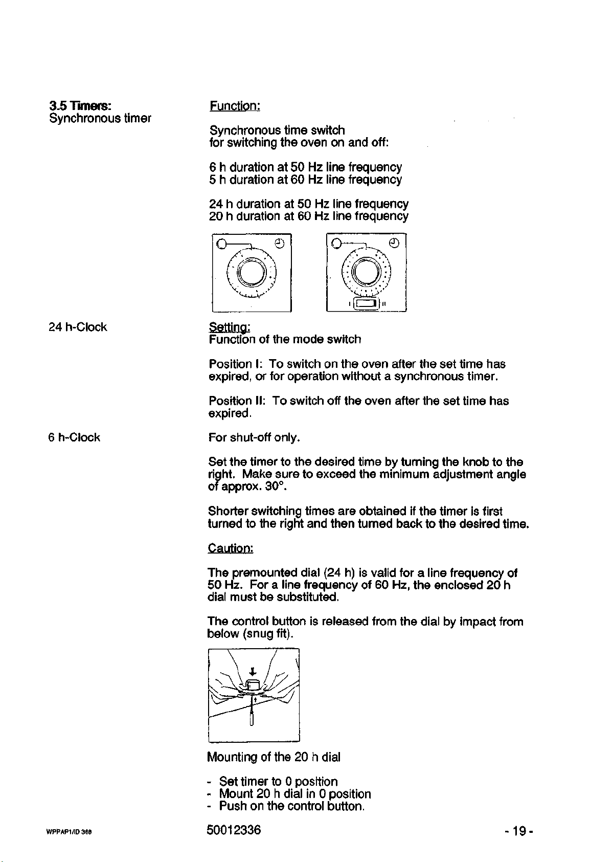
3.5 Timers:
Synchronous timer
Function:
Synchronous time switch
for switching the oven on and off:
6 h duration at 50 Hz line frequency
5 h duration at 60 Hz line frequency
24 h duration at 50 Hz line frequency
20 h duration at 60 Hz line frequency
24 h-Clock
6 h-Clock
Setting:
Function of the mode switch
Position I: To switch on the oven after the set time has
expired,
or for operation without a synchronous timer.
Position II: To switch off the oven after the set time has
expired.
For shut-off only.
Set the timer to the desired time by turning the knob to the
right. Make sure to exceed the minimum adjustment angle
of approx. 30°.
Shorter switching times are obtained if the timer is first
turned to the right and then turned back to the desired time.
Caution:
The premounted dial (24 h) is valid for a line frequency of
50 Hz. For a line frequency of 60 Hz, the enclosed 20 h
dial must be substituted.
The control button is released from the dial by impact from
below (snug fit).
WPPAP1/ID368
Mounting of the 20 h dial
- Set timer to 0 position
- Mount 20 h dial in 0 position
- Push on the control button.
50012336
-19-
Page 54

Daily program
timer
Function:
To switch the oven on and off.
©
Setting:
At the start of operation, set the actual time on the program
dial by turning it to the right.
Select the desired switching times by locking down the
riders.
The locked red dial segments indicate the switch-on times.
Minimum switching frequency 15 minutes.
Weekly program
timer
Function:
To switch the oven on and off.
Set the actual time and weekday on the program dial by
turning it to the right.
1 = Mon., 2 = Tues., 3 = Wed., 4 - Thurs.,
5 - Fri., 6 » Sat., 7 - Sun.
Select the desired switching time by locking down the
riders.
Minimum switching frequency 2 hours.
Mode converter:
Digital weekly
program timer
WPPAP1/ID368
automatic operation with timer.
manual operation: timer out of operation.
See separate operating instructions.
50012336
-20-
Page 55

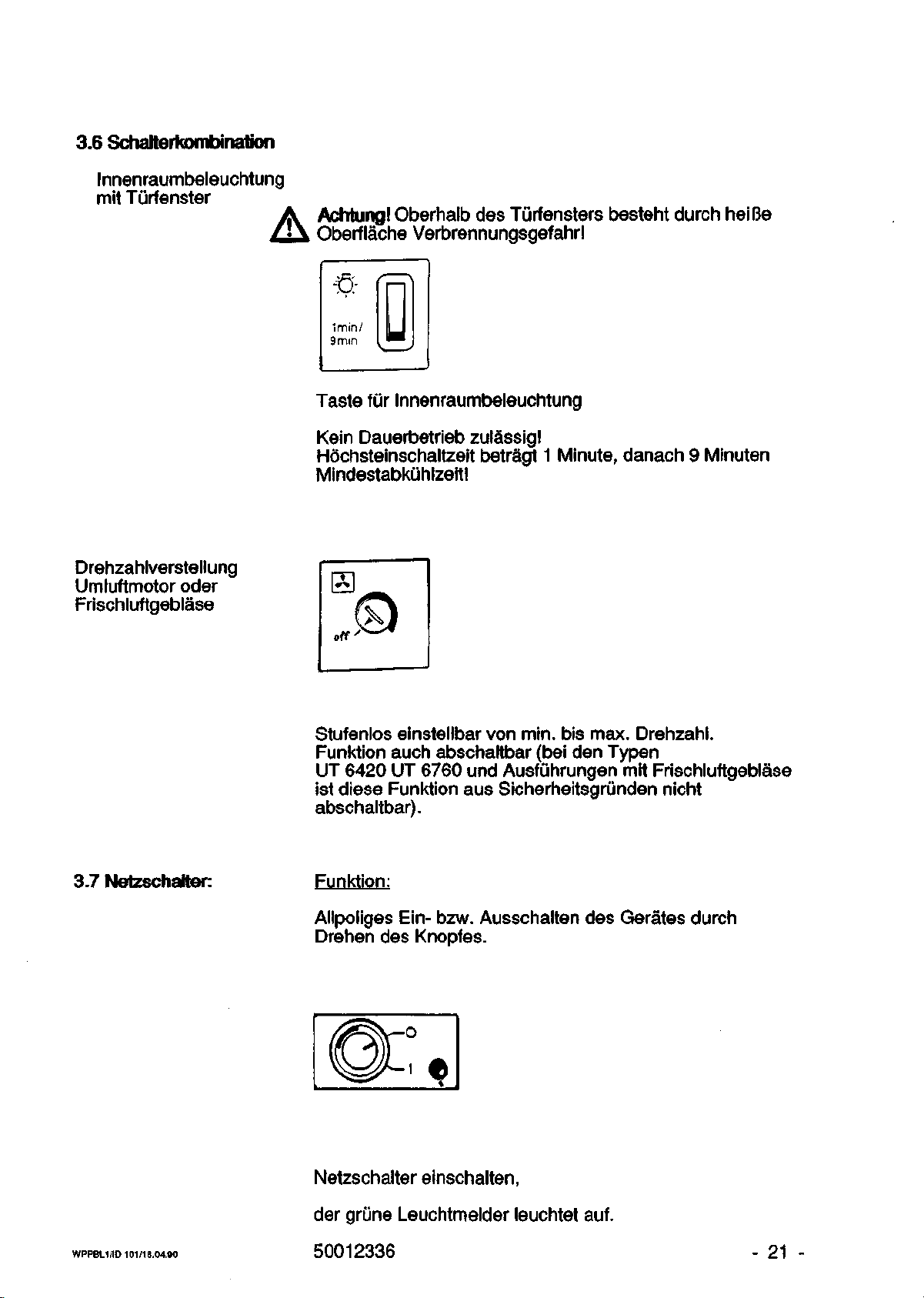
3.6 Switch combination:
Interior lighting
with door window
Speed regulation
of air-circulation
fan motor or fresh
air blower
Caution!
Hot surface above door window can cause burns I
•s-
Imin/
9min
Interior lighting switch
Continuous operation not permissible!
Maximum on time is 1 minute, followed by a minimum
cool-down period of 9 minutes!
1
3.7 Master Switch:
Infinitely variable from min. to max. speed. Function can
also be switched off. For safety reasons, it cannot be
switched off with types UT 6420/UT 6769 and fresh air
blower-equipped units.
Function:
Turn the knob to switch the oven on/off at all poles.
Turn on the master switch
- The green pilot lamp lights up.
WPPAP1/ID368
50012336
-21 -
Page 56

4. Commissioning
Shelves and
supports
The shelves and their supports are secured inside
the oven for transport. The transport guards must be
removed before the oven is put into operation.
The supports can be inserted at any place in the perforated
rows.
The shelves slide over the supports in such a way
that the fork-shaped stabilizer catches the lower side of the
support.
The working space proper is defined as that space which is
1/10 less than the overall chamber of the respective model,
(cf. also DIN-Standard 12 880 Part 2).
Note on loading
Caution
Only this part of the chamber may be loaded.
Do not load the bottom of the oven!
Don't arrange the load too closely on the shelves (load only
70%
of the area), so that air circulation is not impaired and
uniform heating is ensured.
Close the door.
Turn on the master switch.
- The green pilot lamp lights up.
Set the temperature controller to the desired working
temperature.
After the desired temperature has been reached, set the
temperature safeguard.
The door surface is hot
WPPAP1/ID 36B
- around the windows
- around the central edge of the doors
(only with model 6760)
50012336
-22-
Page 57

5. Maintenance and
Repairs
The oven should, at reasonable intervals, be tested
for proper operation. This applies especially to the
temperature limit cut-out/controller.
The safety of the oven and its conformity with the relevant
standards will be guaranteed only if maintenance work,
repairs and/or modifications are carried out by authorized
personnel.
Before any maintenance or repair work is carried out, the
oven must be disconnected from the line.
Readjusting the
door
1.
Adjusting the catch
2.Adjusting the
bearing pin
If the door no longer closes properly, adjust the
bearing pin and the catches:
Loosen the catch nut M6 with a wrench (size 10) and
turn the catch clockwise for at least one complete
rotation.
After this, return the catch to the same position.
Retighten nut M6.
Loosen the Phillips screw of the bearing pin.
Use a small spindle to prevent the bearing pin from
rotating also. After you've loosened the screw, turn the
bearing pin with the spindle, and determine the desired
setting for height and depth. Retighten the Phillips screw
and check if the door fits tight.
Replacing the gasket
Removal of the
internal fittings
WPPAP1/ID 368
Remove the defective gasket and install a replacement.
After that it is imperative that the unit be tested for
tightness. Make sure to reinstall the clamps.
Use a Phillips screwdriver to remove the internal
fittings in the working chamber.
- Unscrew the bottom plate
- Unscrew the lateral cooling baffles
- *Unscrew the rear wall covering
- Remove the individual internal fittings
*only with UT ovens
50012336
-23-
Page 58

Hints on care Inner casing:
Commercially available detergents in small quantities
should be used, but no acids, no chloric solvents or saline
solutions.
Control elements (modules):
It is best to wipe these only with a damp cloth.
Spare parts If you have complaints or wish to order for spare parts,
please state the data on the nameplate.
A list of spare parts can be requested either from your local
Heraeus representative or directly from the factory. State
the model type and serial number.
Wiring diagrams BR 6000 220 V/l A.C. 500 11 620
BR 6000 110 V/l A.C. 500 30 370
BR 6000 380 V/3 A.C. 500 11 621
BR 6000 220 V/3 A.C. 500 30 371
WPPAP1/1D 368
50012336 -24-
Page 59

6. Appendix - Table 3, from DIN-Standard 12 880
Safety devices against malfunction of the temperature control circuit.
Classification of heating ovens according to DIN-Standard 12 880 Part 1, table 3.
The class describes the type and scope of protection, as well as the safety measures
required to deal with a simple defect in the temperature control circuit.
Class
0
1
2
3
3.1
Purpose
-
Protection
of oven
Protection
of oven,
environment
and material being
treated.
Scope
-
In
the
event
of a
defect,
emanates from
oven.
In
defect,
emanates from
oven
terial being treated.
In
the
defect,
being treated
tected against overheating and/or undercooling (e.g. incubator)
the
or
no
danger
event
no
danger
from
event
the
the
of a
the
the ma-
of a
material
is
pro-
Safety device
ace.
to
Sub-
section
5.5
-
Temperature
11 miter
or
thermal fuse
Adjustable
temperature
limit cut-out
Adjustable
temperature
limit
controller,
coming into
action
case
in
of:
excess
temperature
Safety measures
Only attended opera-
tion*) with harmless
materials
ted;
is excluded
1s
or
overheating
permit-
by
con-
structional measures.
Special safety measures depending
the intended
on
use.
3.2
Insufficient
temperature
excess
3.3
temperature
and
insufficent
temperature
*) If operation is supervised, the oven must be checked at reasonably short intervals to
make sure it works correctly.
WPPAP1/ID 368
50012336
-25-
Page 60

Technical Data
T
Materials:
Inner casing
Shelves
1.4301
Chromi um-
plated steel
Door gasket
Heating
Outer casing
*) Stainless
**)
and
Sil.
1.4435
acid-resistant steel
**) Galvanized, sheet-steel outer
Colours:
Outer casing,
grey-white
RAL 9002
Modules,
agate-grey
RAL 7038
Operating elements,
1ight-blue
RAL
DimensionsCmm)
see dimensioned
sketch
P.29
External dimensions
*
Casing
T^
incl.
door
handle
B
A
HA
6030
*)
rubber
*)
5012
610
552
552
6060
T
UT
1.4301
*)
Chromi umplated steel
Sil.
rubber
1.4435
c
:oating with
RAL 9002
RAL 7038
RAL
5012
610
647
744
744
552
552
*)
T
1.4301
Chromi umplated steel
Sil.
1.4435
hes
it-resistant
RAL 9002
RAL 7038
RAL
610
895
696
6120
UT
*)
rubber
*)
5012
647
895
696
6200
T
UT
1.4301
Chromi umplated steel
Sil.
rubber
1.4435
po'
yester varnish.
RAL 9002
RAL 7038
RAL
5012
790
827
895
895
816
816
*)
*)
6420
T
UT
1.4301
*)
Chromiumplated steel
Sil.
rubber
1.4435
*)
RAL 9002
RAL 7038
RAL
5012
790
744
1813
1838
6760
T
UT
1.4301
*)
Chromiumplated steel
Sil.
rubber
1.4435
*)
RAL 9002
RAL 7038
RAL
5012
790
1200
1813
1838
Internal dimensions
TT
H
i
Horki ng-chamber
volume
WPPAP1/1D 368/19.04.90
(1)
370
352
231
30
50012336 - 26 -
370
339
403
403
380
380
57
52
370
323
554
554
524
524
107
94
550
503
554
554
644
644
196
180
550
544
1366
409
522
544
1319
375
550
522
1000
1000
1366
1319
751
689
Page 61

Technicai Data
Heights
Electrical data:
Tines:
(kg)
Empty weight
max.
charge
max.
shelf load:
surface
spot
Rated voltage
Rated freq.
Rated current
Rated power
(minutes)
Heating-up time
(air-flap closed)
from 25°C
300°C
150°C
70°C
Recovery time
(door opened
1 min)
the initial value
to
to:
997.
at:
300°C
150°C
70°C
(V)
(Hz)
(A)
(kW)
for
of
T
50
6030
40
50
20
15
220
/ 60
3.4
0.75
75
30
15
7
6
2
T
50
6.5
1.4
35
10
10
50
6
4
4
6060
50
20
15
220
/ 60
6
1
UT
53
.8
.49
55
20
10
6
3
1
T
65
9.3
2.0
60
20
10
50
9
4
4
6120
50
20
15
220
/ 60
10
2
UT
75
.3
.25
60
25
15
11
5
1
T
92
11.1
2.4
65
30
20
10
50
5
5
6200
75
40
20
220
/ 60
UT
100
12.2
2.65
75
23
10
6420
T
153
380
50
6.5
3.6
70
35
7
2
2
40
18
11
6
UT
163
75
40
20
/ 60
6.8
3.8
80
30
10
6
6
1
T
223
8.2
5.4
80
55
55
5C
8
5
3
6760
150
40
20
380
)
/ 60
UT
241
8.6
5.6
85
30
12
11
6
1
Air changes
Air flap open
WPPAP1/1D 368/19.04.90
per h
300° C
150°C
70°C
33
34
14
50012336
14
12
33
35
7
36
25
21
19
27
29
32
21
15
11
28
41
47
21
16
11.
21
19
5
47
12
14
10
12
18
10
- 27 -
Page 62

Technical Data
6030
Max. fresh
T
air
T
quantity (nr/h)
(air flap open)
I
300 °C
150°C
70°C
with
UT
at
max. fan
models
.4
1.45
0.6
1.06 2
0.91
0.53
power
quantity
lated
of
recircu-
air (at
max.
fan
25°C)
power
-
in nr/min
*Holding power
(Hh/h)
air flap closed
at 300°C
150°C
70°C
5
150
55
550
200
75
41
Temperatures**:
Rated temp.
Variation
space
in
(°C),
300°
C
air flap closed
300°C
150°C
70°C
Fluctuation
at
rated temp. <°C>
Accuracy
temp,
of
display
±
±
±
<
5.
2.
1.
0.
3
0
4
5
±5 ±
±4 ±
±2 ±
<
Telethermometer
in
% of
scale reading
full-
±
3
±
Digital display
in
% of ful1-
1
±
±
scale readinq
*
corresponds to the heat
**
measured in accordance with DIN-Standard 12 880,
WPPAP1/1D
368/19.04.90 50012336
oad of the
installation area
6060
2
2
-
2
300°C
0.5
3
1
UT
.5
.65
.73
.3
900
410
185
6
3
1
Part
2.
T
3.41
2.86
2.6
780
265
85
±
6
±
4
±
2
6120
-
30C
<
0
±
3
±
1
)°C
±
±
±
5
UT
3.68
3.96
4.36
6.5
1280
580
265
7
2.4
0.9
6200
T
UT
5.04
6.7
3.6
9.8
2.64
11.27
-
4.1
1000
1570
350
695
120
325
300°C
±
5.5 ± 5.6
±4
±3.1
±
1.8 ± 1.3
<L
0.5
±
3
±
1
6420
T
UT
10.3
10.3
7.8
9.8
5.6
9.8
6.4
1800 2500
610
1100
210
420
300 °C
±
3.6 ± 3.6
±
3.5 ± 2.9
±
2.9 ± 0.8
<
0.5
±
3
±
1
T
10.3
12
8.6
2600
890
280
±
4.
±
4.
±
2.
6760
-
300°C
8
± 4.4
9
± 3
4
± 1
j<
.
0.5
H
:
3
j
r
1
10.3
15.5
8.6
7
3300
1250
520
UT
-
28 -
Page 63

Dimensioned Sketches
m
1
1
1
1
I, i;
U
1
1
f\
1
I
1
1
1
1
6030.6420.6760
u
J
TA
6060.6120.6200
WPP
AP1/1D
388/19.04.00 50012336
- 29 -
Page 64
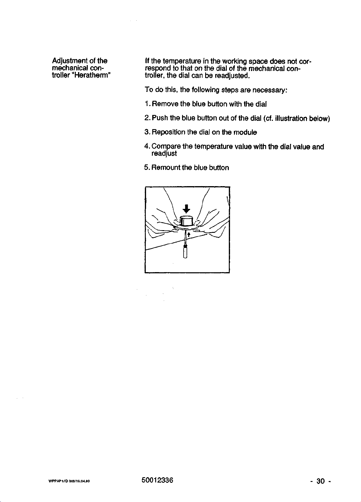
Adjustment of the
mechanical con-
troller "Heratherm"
If the temperature in the working space does not cor-
respond to that on the dial of the mechanical con-
troller, the dial can be readjusted.
To do this, the following steps are necessary:
1.
Remove the blue button with the dial
2.
Push the blue button out of the dial (cf. illustration below)
3. Reposition the dial on the module
4.
Compare the temperature value with the dial value and
readjust
5. Remount the blue button
WPPAP1/ID 368/19.04.90
50012336
- 30 -
Page 65

Eurotherm Controller with Interface RS 232
Assignment of the 25-pin
13 1
O 6 OO OvO 0 0 0 0 0 0 0
0 0 0 0 OJO 0 0 0 0 0 0
25 14
— All unlisted pins are not wired
The interface pin assignment is designed to permit direct connection to an IBM or
IBM-compatible computer if the computer is equipped with a 25-pin
interface has a 9-pin
plug) can be used.
plug,
D-Sub
a commercially available adapter (9-pin socket and 25-pin
socket:
P1n
1
20
Shield
2
Rx < reception
3
Tx ( transmi
4
( connected
5
( connected
6
( connected
7
COM ( common
8
( connected
< connected
ssior
to
to
to
,
to
to
plug.
If the computer
)
5
4
8
ground)
6
6
l )
)
)
and
and
and
20
20
8
)
)
)
Upon delivery of the unit, the controller address is set to 00, and the Baud rate to 9600.
For other addresses or other Baud rates, the controller must be reconfigured (see
operating instructions for the EUROTHERM controller).
WPPAP1
/ID 366/19.04.00
50012336
- 31 -
Page 66

Eurotherm Controller with Interface RS 485
Assignment of the 25-pin
13
0000000000000
oooo
25
14
olo
oooooo
All unlisted pins are not wired
D-Sub
1
socket:
Pin
1
12
13
16
20
Shield
2
( connected
3
Tx
+ <
4
( connected
5
( connected
6
( connected
7
COM < common, ground)
8
( connected
Rx
+ (
Rx
- (
Tx
- (
( connected
to 12
transmission
to
to
to 8 and 20
to 6 and 20
reception
reception
transmission
to 6 and
)
+ )
5 )
4 )
)
)
+ )
- )
- )
8)
Upon delivery
For other addresses
operating instructions for the EUROTHERM controller).
Caution:
of
the unit, the controller address
or
other Baud rates, the controller must be reconfigured (see
In the case
may be necessary to change the polarity
controller does not respond
PC interface to Txthe controller.
of
some RS 422/485 interface cards for personal computers,
to
the computer interface, connect Rx+
of
the controller, and Tx+
is
set to 00, and the Baud rate
of
the signals Rx and Tx.
of
the PC interface to Rx-
to
If
9600.
the
of
it
the
of
WPPAP1/ID 366/19.04.90
50012336
-
32 -
Page 67

PMOO
Horizontal version
Vertical version
NiCr-Ni connection
- Subject to modifications -
WPPAP1 /ID 368/10.04.00
50012336
- 33 -
Page 68

ZltH B8'E0'SI b ONUIS 3ZIU1HU
>•
O Cu
ro z
r^ ro
o c_
^ ro
o
(N!
11
ID
1
>•
ro
(NJ
II
e
CNl
1!
1 CC
>• cr
CO tO
CNI *
Z3 ft
•>•
o
CNJ
II
rD
ti
UJ
Ci
tl
u
w
r.
r
ro
•>
r
r
u
" cn
j
1
c
UJ
0"
CN
cn
to
c
r-
(M
cr
a
r-
LT
O~
CD
LD
CNI
-*r
CT)
ro
O
CD
cn
cn
CO
o
o
ro
CD
r-
o
o
(NJ
cn
CD
ro
r-
o
o
CD
LO
CD
ro
_
o
o
LO
CNI
LO
m
CD
to
cc
CT
ro
CN
to
cr
cr
CC
LD
CC
CC
CD
ro
to
LO
o
CM
tr-
V-
CO
CD
LO
ee
o
r-
r-
CO
•V
—
CD
to
CO
cn
LO
ro
LO
„
—
o
CO
O"
CO
O"
CNJ
o
cn
CO
ro
cr
CD
(M
to
o
*->
ro
CT:
CM"
Csl
CD
to
ro
r-
CD
1
i
i
u
CO
CS)
r-
CO
cz
(NJ
cr
LO
CNJ
c:
CNl
to
o
CNJ
cn
Csl
cc
a
cc
u
CO
Cs
r-
CN
tc
«w
CN
CNl
CO
. CO
o
cr
cn
LO
o
cn
LO
O
CO
ro
o
i
j
CS
Lft
Cf
CSJ
CO
(NJ
L7
to
CNJ
CNl
in
CNl
CNl
°
ro
CO
ro
CO
CNJ
m
—
Csl
CD
CNI
c
c
u
c
1.
r-
' ro
—.1
•>
t/
CN
CD
, m
CO
i/
(T
°
if
V
(SJ
r-
CO
U"
[->
o"
LT
cr
LO
tc
r-
CD
in
CO
tn
1
a
LO
U
cr
•<-
U"
U
Cf
ro
r-
CT)
ro
"L
ro
rsJ
ro
r-
cr
c
tc
tn
"«r
r~
ro
°^
LO
LD
LD' —
^r
COj O
ro
m
> ro
1 rsj
r
ro
—
1
t*
J
a
""j IT)
a
!
c
a
1
• m
V
j
LO
CN
—
CC
ts
IT
\r
CO
to
CO
"~
ro
M
!
f
LD
- LO
u
J
CT
(/
CSJ
O"
CC
LO
to
cc
tr
LO
A m
cz* —
CC
J °
K
l
to
to
rco
°
CD
E:
ro
CD
o
CO
CD
cn
ro
CD
"
in
ro
cn
CNI
LD
LO
"~
*~
LO
cn
CNl
CD
CO
CD
ro
CNlj
•«"
CD
to
cn
(NJ
o
CD
O
•™
CS)
cn
-
to
ro
CNJ
o
to
Ln
o
CD
cn
CD
LO
Lo"
cn
ro
o
to
LO
ro
CD
CO
cn
cn
CO
CO
to
r-
n
o
csj
*~
•ZD
>LO
t!
ID
0 V-
11
LO
-
rsi
ro
o
CNl
CM
o
cn
CNI
CD
o
o
CO
,28
o
r~
cn
*~
LO
CO
r-
CD
o
LO
cn
r-
.*-
r-
ro
»
o
O
cst
CNI
CO
CO
ro
CO
CD
o
CD
LO
r-
CO
CsJ
CO
O
o
LO
to
CO
LO
—
°
CSJ
cn
cn
CO
CO
CD
-
(SJ
CNI
rsj
CNI
LO
ro
•*~~
in
CD
cn
LO
CD
ro
CSI
ro
CO
CO
CT)
•»r
r-
—
ro
O
m
CO
r--
LO
o
ro
-
ro
CO
CM
CD
ro
ro
o
cn
r»
CO
ro
rsi
o
m
r-
CNI
to
LO
o
to
to
CO
LO
CD
CO
CO
LO
LO
O
cn
•*r
]
LO
O
cn
CD
CO
LD
cn
CO
r-
•«-
CSI
CO
r-
o
cn
LO
[-•
CO
to
o
CO
LO
"~
z
CNI
LO
ro
,15
O
*~
CO
ro
J
CD
!
LO
Csl
o
r-
(NJ
CD
CD
CD
O
LO
CO
cn
CNl
LO
ro
D
CO
CO
CNI
ro
CNI
cn
o
CsJ
CD
LO
-<-
o
(SJ
CSJ
to
to
CD
LO
CO
CD
cn
O
1
cr
•—•
CD
(_D
o
to
cn
LO
CO
COj
CNl
CO
rsi
cn
o
CD
O
cr
(
n
D_
CD
CD
CD
to
1—
to
1—
ZD
—
cr
n
•~~*
cu.
o
to
o
CD
1—
1—
CO
CNI
to
o
CNl
CC
cr
11
CL.
o
CS)
to
CD
n
II
n
*—'
o
CSJ
CD
to
to
•=>
to
1—
ID
rsi
CD
o
ro
o
cc
cr
cr
u
|?
II
1 i
o
CD
CNI
CD
LD
CD
II
IO-
CD
o
(NJ
CD
1—
CO
cn
O
LO
LO
LO
O
zz.
3:
cr
cr
CD
CD
o
CNl
to
to
t—
to
ID
CD.
rr
cr
cr
(
I!
CX_
CD
CD
1—
to
^_
t—
ii
o
CNl
to
to
ID
cn
CD
LO
LO
cn
—
LO
O
O
cr
it
i .
CD
ro
o
to
m
IX
cr
1
n
1
. i
°-
o
o
CD
1—
to
1—
"~~
r-
to
CO
to
r-
CD
CD
cr
(
a,
o
to
cr
n
(
n
—, a.
o
r-
~>
=
11
cu
•~*
o
to
r-
CO
to
^_
I—
 Loading...