

HEPER PINA DUO WAL Maintenance Instructions
1 4 2
5
6
3
HEPER Lighting
Uygurlar Cd. No:1 06935 &
Organize Sanayi
Bölgesi/Sincan/Ankara
Turkey
Tel: +90 312 267 54 30
Fax: +90 312 267 54 31
info@hepergroup.com
www.heperlighting.com
PINA DUO WALL
Installation&Maintenance Instructions
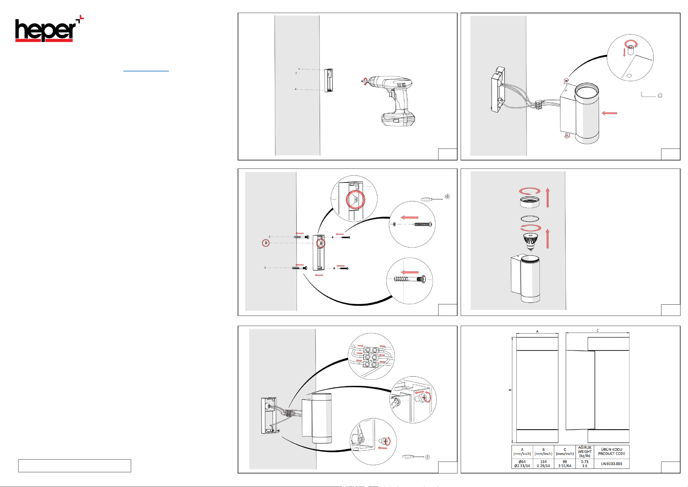
1.
1.
4.
2.
3.
2x3.9x30 mm
Flat Head Screws
2x Ø3 Oring
4 Nm
1.
2.
3.
1.
2.
2xM4 Setscrews
S3
2Nm
1.
2.
2x Plastic Dowels
2xM4 Cross Slotted
Head Bolts
2 Nm
REV 0/01.15.2021
Türkçe
English
MONTAJ TALİMATLARI
Armatürü montaj yapmak için;
1. Armatür bağlantı parçası, duvara konumlandırarak duvarı işaretleyiniz ve Ø 6.5 mm lik
matkapla 50 mm derinliğinde deliniz. Kablo yuvası da, kullanılacak boru çapına göre
delinmelidir.
Not: Armatür bağlantı parçası yere paralel, duvar yan yüzeyine dik olmalıdır.
2. Armatür bağlantı parçasının montajını yapmak için;
2.1. Duvara açılmış olan deliklere plastik dübelleri çakınız (2 Adet, Ø6 plastik dübel).
2.2. Duvardan gelen güç kablosunu grommetten geçiriniz.
Not: Kabloyu grommetten gerçirdikten sonra, grommetin yerinden çıkmadığından emin
olunuz.
2.3. Armatür bağlantı parçasını duvara sabitleyiniz.
Not: Deliklerin eş merkezli olmasına dikkat ediniz.
2.4. Armatür bağlantı parçasını, oringler ve sac vidaları ile 4 Nm torkla montajlayınız (2 Adet, Ø3
oring, 2 Adet, S3.9*30 ysb sac vida).
3. Armatür kablo bağlantılarını yapmak için;
3.1. Armatürden gelen kabloları ve duvardan gelen kabloları klamens ile birbirine bağlayınız.
3.2. Klamensten gelen toprak kablosunu(PE) armatüre 2 Nm torkla montajlayınız (1 Adet, M4
bombe başlı civata).
3.3. Klamensten gelen toprak kablosunu(PE) armatür bağlantı parçasına 2 Nm torkla
montajlayınız (1 Adet, M4 bombe başlı civata).
4. Armatürün, armatür bağlantı parçasına montajını yapmak için;
4.1. Armatürü, armatür bağlantı parçasının üzerine konumlandırınız.
4.2. Armatürü sabitlemek için civataları 2 Nm torkla montajlayınız (2 Adet, M4 setskur).
Armatürün ampulüne ulaşmak için;
Not: Bu işlemi yapmadan önce armatüre gelen elektrik kesilmelidir.
5. Ampul değişimi için;
5.1. Armatür cam gövdesi ve oringi söküp yerinden yerinden alınız.
Not1: Armatürden çıkarılan oringin düşmemesine dikkat ediniz.
Not2: Armatür cam gövdesi yerine montajlanacağında, sökülmeden önceki oringe yapılan
baskının aynısının yapılması gerekmektedir.
5.2. Ampulün, duy slotlarının içine giren tırnakları, yerinden çıkana kadar saat yönünün tersine
çevirin ve ampulü alınız.
ASSEMBLY INSTRUCTIONS
Luminaire Installation;
1. Position the luminaire surface mounting back box on the wall and mark the mounting
hole locations.
Note: Doublecheck that mounting box is plumb before final drilling. Drill anchor pilot
holes with a Ø 0.6.5 drill bit. The supply cable entry should also be drilled to
accommodate the conduit diameter to be used.
2. To install the luminaire connector part;
2.1. Drive the plastic dowels into the pilot holes made in the wall. (2 pieces, Ø6 plastic
dowels).
2.2. Pull supply power wires into surface mounting back
Note: Make sure grommet is still in place after pulling supply wires into surface
mounting box.
2.3. Fix the luminaire connector part to the wall.
Note: Make sure that the holes are concentric.
2.4. Align surface mounting box holes with anchors and affix the back box to the
wall using 2 pieces, Ø3 oring and 2 pieces, 3.9x30 mm screws. Tighten to 2.9
lb ft torque.
3. Making electrical power connections;
3.1. Connect the cables
wall with the supplied terminal.
3.2. Mount the ground wire (PE) coming from the terminal to the M4 round head
ground screw on the back box.
3.3 Tighten grounding screw to 1.5 lb ft torque.
4. Mounting the luminaire to the surface mounting box;
4.1. Position the luminaire on the surface mounting back box.
4.2. Affix the luminaire, to surface mount back box using 2 Pieces, M4 set screws (S3
Allen head). Tighten set screws to 1.5 lb ft torque.
To reach the bulb of the luminaire;
5. Lamp replacement;
Not: Before performing this operation, make sure electricity off at breaker box/panel.
5.1. Remove the luminaire lens cover and o-ring.
Note1: Be careful not to drop the o-ring removed from the luminaire.
5.2. Turn the lamp counterclockwise until it is free from the GU10 socket. Remove the lamp.
Replace with new lamp following installing lamp instructions above.
Note2: When the lens is replaced, ensure appropriate compression on the o-ring to
achieve weather tight seal.
coming from the luminaire and the cables coming from the
box through the grommet.
 Loading...